

Page 1
Rain Collector Heater
Installation Manual
The Rain Collector Heater may be
used to protect the Rain Collector’s
internal components from freezing
and/or to measure the moisture
content of snowfall. When the
heater is on, it is capable of
melting snow at a rate of 1/4''
(6 mm) of liquid precipitation per
hour. It may not be able to keep up
with larger rates of snowfall.
The rain collector heater warms
only the inside of the rain collector
and the cone itself.
Please note that we have made every attempt to design and manufacture a
safe product, but Davis Instruments assumes no liability for any injury or
damage caused directly or indirectly by the installation or use of this
product.
Note: Although the nominal heater voltage is not hazardous, a short in the wall
transformer could cause hazardous voltage to appear on the heater
wires. For safety, you should always turn the heater’s power unit to the
“OFF” position before removing the rain collector’s cone. We also
recommend that you unplug the wall transformer before removing the
rain collector’s cone.
This instruction manual is designed to take you step-by-step through the
process required to install and use your rain collector heater. Please take the
time to read through this manual before beginning the process.
Components
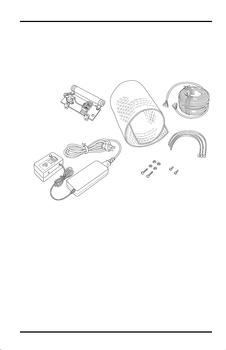
The rain collector heater includes the following components. Please make
sure you have all listed components before continuing.
• Heater Assembly — Includes heater element, thermostat, and terminal
block for power cable.
• Wall Transformer with Power Unit
• Insulation Blanket
• 50' (15 meter) Heater Cable
1
Page 2
Components
The Installation Hardware Kit includes:
• Three Cable Ties
• Two #6-32 x 3/4” Screws
• Two #6-32 Hex Nuts
• Two #6-32 Split Lock Washers
• Two #4 x 3/8'' Self-tapping Screws
Heater Assembly
Wall Transformer
with Heater Power Unit
Insulation Blanket
#6-32 x 3/4"
Screws (2)
with Lock Washers
and Hex Nuts
Heater Cable
50' (15 meter)
Cable Ties (3)
#4 x 3/8"
Self-tapping
Screws (2)
Components
Tools and Materials Needed for Installation
In addition to the components listed above, you will need some of the
following tools and materials. Please be sure you have everything you need
before beginning the installation.
• Medium Phillips-head and Slot-tip Screwdrivers
• Drill with 5/32” (4 mm) or 3/16” (4.8 mm), and 9/32” (7.2 mm) or 5/
16” (8 mm) Drill Bits
• Wire Cutter
• Wire Stripper or Knife
• Cable Clips or Weather-Resistant Cable Ties
2
Page 3
Installing the Rain Collector Heater
Choosing Cable for the Rain Collector Heater
The rain collector heater comes with a 50-foot (15 m) length of 22 gauge
cable. You may use 22 gauge, two-twisted pair wire for cable lengths up to 120
feet (36 m). If you want to use single pair cable, use the following table to
determine the minimum wire size for the desired length of cable run.
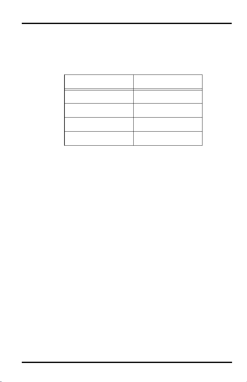
Length of Cable Run Minimum Wire Size
Up to 60 feet (18 m) 22AWG (0.50 mm2)
2
60-100 feet (18-30 m) 20AWG (0.75 mm
100-160 feet (30-50 m) 18AWG (1.0 mm
160-250 feet (50-80 m) 16AWG (1.50 mm
)
2
)
2
)
If the heater cable is routed with any signal cable (i.e. any cable running from
a sensor, junction box or SIM), be aware that for cable runs over 50 feet
(15 m) the heater cable’s voltage may interfere with sensor voltages in the
signal. To prevent this interference, do at least one of the following:
• Use twisted pair for the heater cable or the signal cable.
• Use shielded cable for the heater cable or signal cable (shield must be
grounded).
• Keep the heater cable and the signal cable separated by several inches over
most of the length of the cable run.
Installing the Rain Collector Heater
The instructions below will take you step-by-step through the procedure
required to install the rain collector heater. Make sure the wall transformer is
unplugged until you are instructed to plug it in.
Attaching the Heater to the Rain Collector
1. Remove the rain collector’s cone from the base and, if necessary, remove
the mounting screws from the base of the rain collector.
2. If screw holes for the rain collector heater are not already present in the
base, position the heater as shown on the next page (with the terminal block
facing away from the bucket) and mark the location of the screw holes on
the heater assembly.
3
Page 4
Installing the Rain Collector Heater
Earlier versions of the rain collector did not come with built-in holes for the
rain collector heater. If your rain collector does not have built-in holes you
need to drill them yourself following the instructions below. Otherwise,
skip to step 5.
Marking screw holes
3. Using a drill with a 5/32” (4mm) or a 3/16” (4.8 mm) drill bit, drill holes in
the marked locations.
4. Using a drill bit with a large enough diameter to allow your power cable to
pass through, drill a cable hole in approximately the position shown below.
For the provided 50' (15 m) cable, use a 9/32'' (7.2 mm) or a 5/16'' (8 mm)
drill bit. The precise location of the power cable hole is not critical.
Power cable hole
4
Page 5

Installing the Rain Collector Heater
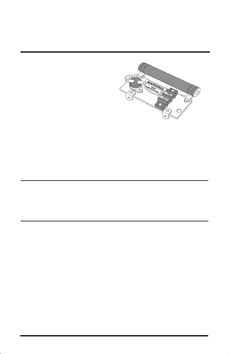
5. Loosen the screw heads on the terminal block.
You will eventually secure the heater cable wires underneath these screw
heads.
Terminal Block
Terminal Block
Screw Heads
Rain collector heater terminal block
5
Page 6

Installing the Rain Collector Heater
6. Secure the heater assembly to the rain collector.
For stand-alone rain collectors (#7852), secure the heater assembly to the
rain collector base using the #6-32 x 3/4” (19 mm) screws, a lock washer,
and a hex nut, as shown below.
Securing the heater in a stand-alone rain collector
Note: Stand-alone rain collectors are used with all Weather Wizard III, Weather
Monitor II stations. Vantage Pro2 rain collectors are included with all
Vantage Pro2 Weather stations.
6
Page 7

Installing the Rain Collector Heater
For Vantage Pro2 rain collectors, secure the heater assembly to the rain
collector base using two #4 x 3/8 self-tapping screws, as shown below.
#4 x 3/8"
Self-tapping
Screws
Heater
Assembly
Knock-out
Hole for
Heater Cable
Securing the heater in an Vantage Pro2 rain collector
7. Using wire strippers or a knife, strip 3/8” (10 mm) of insulation from the
heater cable wires.
8. If you have a Vantage Pro2 rain collector, use a medium size Phillips-head
screwdriver to knock out the hole for the heater’s power cable.
9. Pass the heater cable wires up through the cable hole you just drilled (stand-
alone rain collector) or knocked out (Vantage Pro2 rain collector).
7
Page 8

Installing the Rain Collector Heater
10.Bend each bare wire into a U-shape and secure each one under a screw
head on the terminal block as shown below.
It does not matter which wire goes to each screw as long as only one wire
goes to each screw.
Attaching cables to the terminal block of stand-alone rain collector heater
Terminal Block
Cable Tie
for strain
relief
Heater Cable
Attaching cables to terminal block of Vantage Pro2 rain collector heater
8
Page 9

11.Secure the cable to the heater
assembly by running a cable
tie over the cable and through
the hole as shown. You can
cut off excess cable tie.
12.To provide strain relief for
the cable, place a cable tie
around the cable just above
the hole through which this
cable is running, as shown
below.
You may want to cut off the
excess cable tie.
Installing the Rain Collector Heater
Cable Tie
Securing cable to heater
13.Re-attach (or attach) the rain
collector to the mounting
surface.
Installing the Insulation Blanket
1. Fit the insulation blanket against
the side of the rain collector
cone, pushing it as far inside the
cone as it will go.
If fully inserted correctly, the
blanket should extend all the
way to the top of the cone,
leaving a space of approximately
5/16” (8 mm) at the bottom to
accommodate the base.
2. Re-attach the rain collector cone
(with insulation blanket) to the
base.
Providing Strain Relief
Inserting the insulation
9
Page 10

Powering the Heater
Powering the Heater
Running the Cables
Run the heater cable from the rain collector to the location at which you plan
to plug in the wall transformer/power unit. To prevent fraying or cutting of the
cable, secure it so that it does not whip about in the wind. Use cable clips or
weather resistant cable ties to secure the cable underneath the eaves of your
house/building, or in a location similarly shielded from rain. Make sure the
cable is secure by placing clips or ties approximately every 3-5 feet (1-1.6 m).
Do not use metal staples or a staple gun. Metal staples, especially when
installed with a staple gun, have a tendency to cut the cables.
Note: If your cable run extends more than 50 feet (15 m), keep the heater cable
and the rain collector cable separated by at least a few inches, as
discussed in “Choosing Cable for the Rain Collector Heater” on page 3.
Attaching Cable to Power Unit
1. Remove the base of the power unit by removing the four screws in the base.
2. Loosen the screw heads on the power unit terminal block.
You will eventually secure the heater cable wires underneath these screw
heads.
3. Using wire strippers or a knife, strip 3/8” (10 mm) of insulation from the
heater cable wires.
4. Feed the cable through the hole
in the power unit..
5. Bend each bare wire into a U-
shape and secure under a screw
head on the terminal block, as
shown below.
It does not matter which wire
goes to each screw as long as
only one wire goes to each screw
10
Power unit terminal block
Page 11

Using the Rain Collector Heater
6. To provide strain relief for the
cable, place a cable tie around
the cable just inside the hole
through which this cable is
running as shown below.
You may need to cut off the
excess cable tie in order to
close the power unit.
7. Replace the base of the power
unit.
8. You may now plug the wall
transformer into an outlet.
9. To insure that the heater is
working, you may want to set
Providing strain relief
the power unit to the “ON”
setting and then go to the rain collector to insure that the heater element is
hot.
Note: DO NOT TOUCH THE HEATER ELEMENT OR ANY METALLIC
PORTION OF THE HEATER. You should be able to feel the heat at a short
distance from the heater element.
Using the Rain Collector Heater
You may switch the rain collector heater on and off from the power unit.
• OFF — When the rain collector heater is off, the indicator light on the
power unit is also off.
• ON — When the rain collector heater is on, it is capable of melting snow
at a rate of 1/4” (6 mm) of liquid precipitation per hour. It may not be able
to keep up with larger rates of snowfall. When the rain collector heater is
set to “ON,” the indicator light on the power unit is also on.
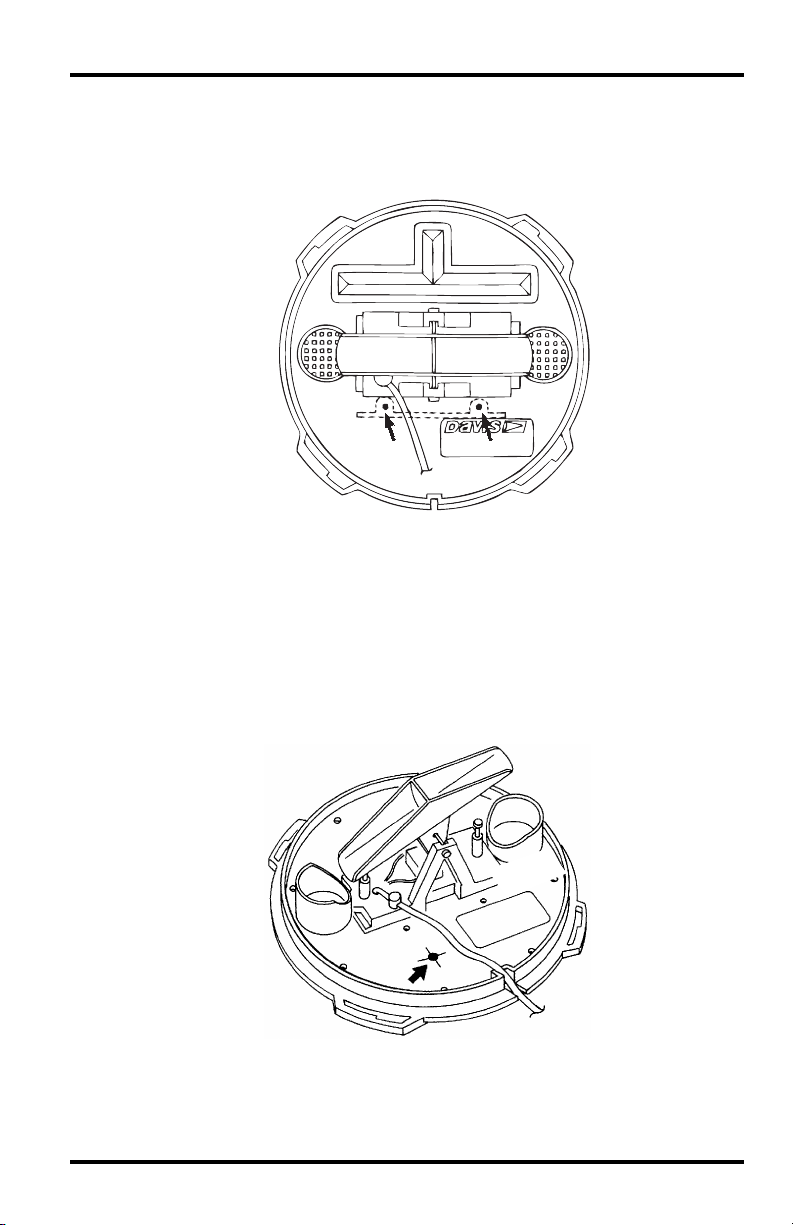
The heater assembly includes a thermostat switch. If the temperature at the
thermostat reaches 110°F (43°C) the thermostat will interrupt power to the
heater element.
11
Page 12

When the temperature at the thermostat drops to about 85°F (30°C) power
flow to the heater element will be resumed.
Location of thermostat
You can turn the heater on when you expect the temperature to drop below
freezing, and turn it off again when you are no longer worried about freezing
conditions.
Product Number: #7720
Davis Instruments Part Number: 7395.096
Rain Collector Heater Installation Manual
Rev. F Manual (8/20/10)
This product complies with the essential protection requirements of the EC EMC Directive 2004/108/EC.
Davis Instruments Quality Management System is ISO 9001 certified.
© Davis Instruments Corp. 2010. All rights reserved.
®
3465 Diablo Avenue, Hayward, CA 94545-2778 U.S.A.
510-732-9229 • Fax: 510-732-9188
E-mail: info@davisnet.com • www.davisnet.com
 Loading...