

Page 1
USER
MANUAL
Radiation
Shield
Product number 7714
R
Davis Instruments, 3465 Diablo Avenue, Hayward, CA 94545-2778 U.S.A. • 510-732-9229 • www.davisnet.com
Page 2

Page 3
Radiation Shield
(7714)
The radiation shield allows the temperature sensor to accurately measure air temperature without the effects of direct radiation from sunlight.
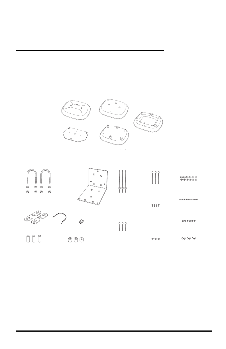
Contents of Package
Radiation Shield Parts
Cover Plate
Support Plate
Installation Hardware Kit
1-1/2" U-Bolts
1/4" Flat Washers
1/4" Hex Nuts
Wall Mount Bracket
Cable ClampCable TieClip Mounts
1" (25 mm) Spacers 1/2" (13 mm) Spacers
Flat Plate
Closed Plates (3)
#8 x 5”
(127 mm long)
Threaded Studs
with Push Nuts
Installed
#8 x 1 3/4”
(44 mm long)
Pan Head Screws
Open Plates (3)
#8 x 2 3/4”
(70 mm long)
Pan Head Screws
#4 x 1/2”
(13 mm long)
Pan head
Self-Threading
Screws
#4 Flat Washers
#8 Flat Washers (12)
#8 Split Lock
Washers (9)
#8 Hex Nuts (6)
#8 Wing Nuts (3)
Tools and Materials Needed
• Small Phillips-head screwdriver and medium slotted-head screwdriver
• Wrench or pliers
• Drill with 3/16” (4.7 mm) drill bit
To drill pilot holes if attaching radiation shield to the top of a post.
• Adjustable wrench or 11/32” (8.6 mm) wrench and 7/16” (10.9 mm) wrench
To tighten hex nuts (11/32” wrench) or to drive lag screws into wall or post (7/16”
wrench).
1
Page 4
• Four 1/4” x 1 1/2” (38 mm long) lag screws
To attach radiation shield to a post or wall.
• Three #8-32 x 1” (25 mm long) screws
To attach radiation shield over the top of a post (if the provided #8 x 2 3/4” pan
head screws create clearance problems).
• Tape
To hold screws in place when assembling the radiation shield.
Location Tips
• The radiation shield works best when in a location with a steady breeze. Mount
away from fences, buildings, trees, or other obstructions.
• Install over plants or soil if possible.
• Do not install over or near sprinklers. The radiation shield is not designed to
protect the sensor from water sprayed upward.
• If attaching to a building, the preferred location would be on the north side in the
Northern Hemisphere and on the south side in the Southern Hemisphere.
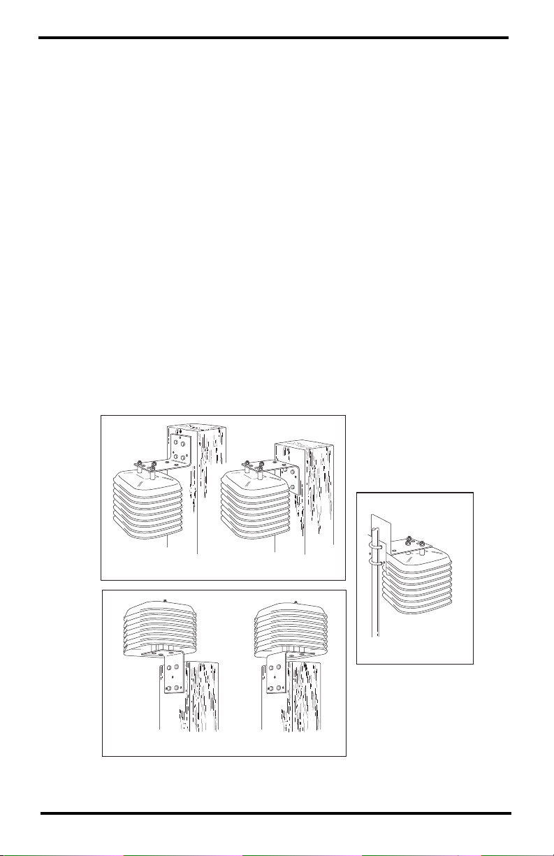
Installation Options
The radiation shield may be mounted in three basic configurations: on the side of a
wooden post or a wall; on a metal pipe with outside diameter between 1” and 1 1/4”
(25 mm and 31 mm); or on top of a wood post. Each of these configurations is
illustrated below. Each orientation requires slightly different installation.
Mounting on the Side of a Post or Wall
Mounting on a Pipe
Mounting on Top of a Post
2
Page 5
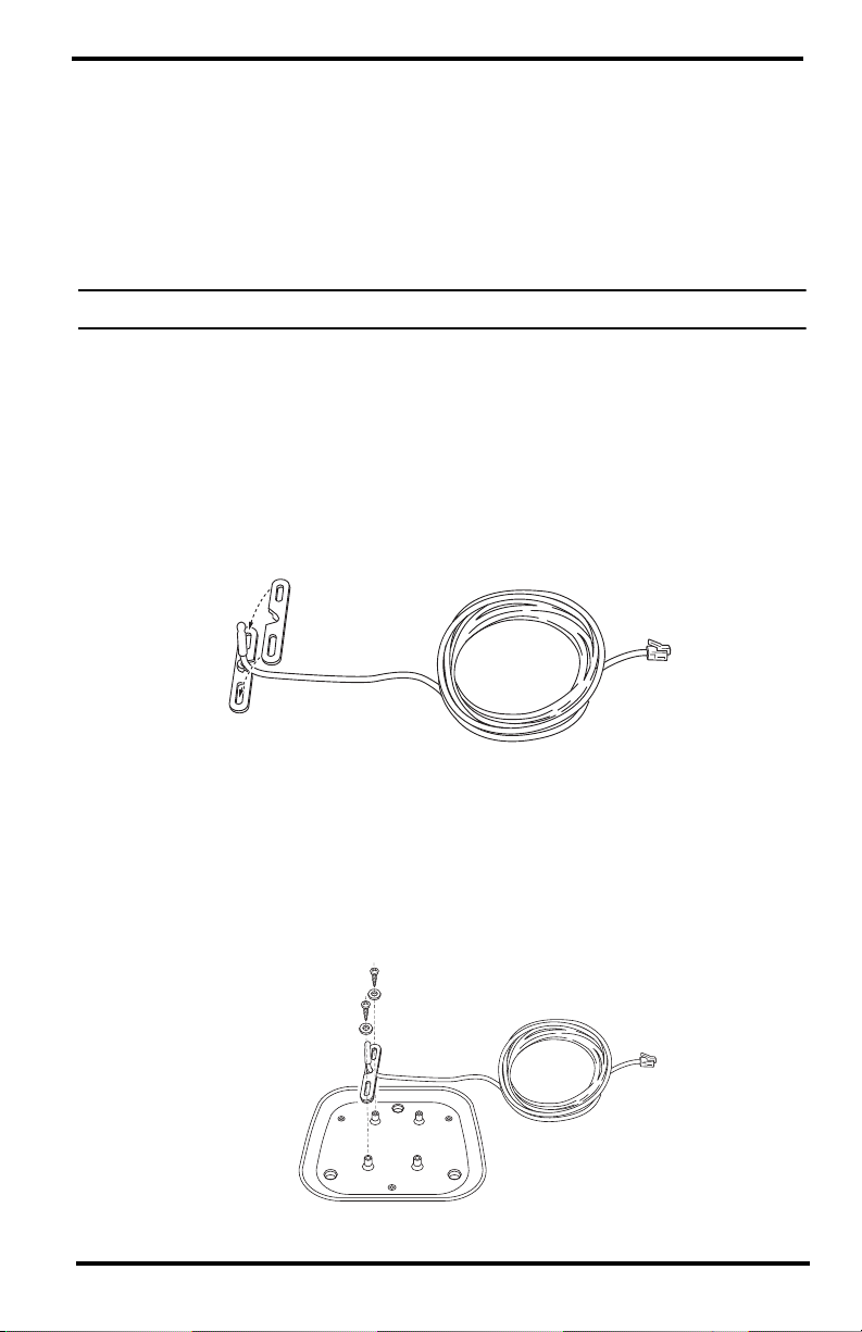
Attach the Sensor
Use the radiation shield to house an external temperature sensor (Temperature
Probes with RJ Connector, p/n 7817 or 6477; or Stainless Steel Temperature
Probes: with RJ connector, p/n 6475 or with Two-Wire Termination, p/n 6470).
In order to attach the temperature probe to the radiation shield, you will need a
closed plate, both clip mounts, the cable clamp, three #4 x 1/2” pan head, selfthreading screws, three #4 flat washers, and the temperature probe.
Note: Illustrations show a Temperature Probe with RJ Connector.
1. Place the sensor cable into the notch on one of the clip mounts and hold it in
place. Make sure to hold the clip mount so the raised semi-circle at the top of
the notch faces up.
2. Position the second clip mount over the first, with the notch facing in the
opposite direction, securing the sensor cable between the two notches.
When positioning the second clip mount, make sure the raised semi-circle
faces down.
Clip Mounts
3. Position the clip mounts over two of the mounting posts on the closed plate.
Make sure you orient the clip mounts as shown in the illustration below.
4. Attach the clip mounts to the mounting posts using two of the #4 x 1/2” pan
head self-threading screws and two of the #4 flat washers.
#4 x 1/2" Screw
#4 Flat Washer
3
Page 6

5. Once secured, adjust the position of the sensor so the probe and
approximately 1/4” (6 mm) of cable protrude from the clip mounts.
6. Place the cable clamp around the sensor cable approximately 8” (20 cm) from
the probe.
7. Secure the cable clamp to one of the remaining mounting posts (using a #4 x
1/2” pan head self-threading screw and a #4 flat washer) so that a loop of
cable is formed.
Make sure to tighten the clamp with the flat side up and the bulge side down.
Tighten the screw completely so that the cable cannot move within the cable
clamp. If using a stainless steel temperature probe, wrap a cable tie around the
sensor and cable as shown below to hold the probe in place.
Cable Tie
Temperature Probe
Cable Clamp
Cable Clamp
Stainless Steel Temperature Probe
4
Page 7

Attach the Support Plate to the Cover Plate
To attach the support plate, you will need the cover plate, the support plate, three #8 x 2 3/4” pan head screws, three 1”spacers, three #8 flat washers, three #8 split lock washers, and three #8 hex nuts.
1. Slide the three #8 x 2 3/4” pan head screws up through the non-threaded holes
in the shield support plate.
Make sure the side of the support plate marked “UP” is in fact on top as you
slide the screws in from the bottom.
2. Place the cover plate over the screw ends protruding from the support plate.
3. Place a 1” spacer over each of the screw ends.
4. Secure the support plate and spacers to the cover plate using a #8 flat washer,
#8 split lock washer, and #8 hex nut on each of the screw ends.
Tighten until the support plate is firmly attached to the cover plate.
#8 Hex Nut
#8 Lock Washer
#8 Flat Washer
1" Spacer
Cover Plate
Support Plate
Cover Plate Assembly
#8 x 2-3/4"
Pan Head Bolt
5
Page 8
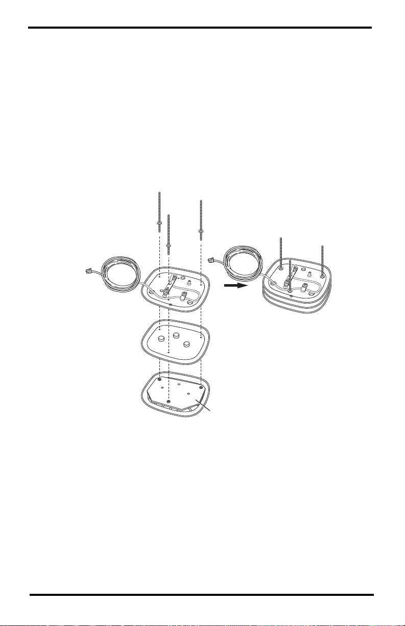
Assemble the Plates and Studs
To assemble the plates and studs, you will need the cover plate assembly as well
as the flat plate and close plate with sensor, three #8 x 5” threaded studs with
attached #8 push nuts, three #8 flat washers, three #8 split lock washers, and three
wing nuts.
1. Slide each of the three #8 x 5” (127 mm) threaded studs, with push nuts
installed, through each of the three holes in the closed plate, flat plate, support
plate, and cover plate.
When inserting the threaded studs, make sure the short end (when measured
from the push nut) goes through the plates. Screw the short end of the
threaded stud in until the cupped side of the push nut bottoms inside the recess
of the closed sensor plate. Tighten as much as you can by hand.
Threaded Studs
with push nuts
Closed Plate
with Temperature
Sensor
Plates and Studs
Assembly
Flat Plate
Cover Plate
Assembly
Support Plate
2. Place the plates and studs assembly aside and proceed to the appropriate
instruction for your installation.
If you are attaching your radiation shield to the SIDE of a post or a wall,
continue to "If you are attaching the radiation shield to the side of a post or
to a wall or a pipe:" (page 7).
If you are attaching your radiation shield to the TOP of a post, continue to"If
you are attaching the radiation shield to the top of a post:" (page 8).
6
Page 9

If you are attaching the radiation shield to the side of a post or to a
wall or a pipe:
1. Slide the three open plates and the two remaining closed plates over the
threaded stud ends protruding from the top of the plate and studs assembly.
Closed Plate
Closed Plate
Open Plate
Open Plate
#8 Wing Nut
Open Plate
#8 Lock Washer
#8 Flat Washer
Plates and Studs
Assembly
Complete Plate
Assembly
2. Place the flat washers, lock washers and plastic wing nuts over the protruding
stud ends.
3. Rest the partially assembled radiation shield on a flat surface and proceed to
mount the shield. See “Mount the Radiation Shield” on page 11.
7
Page 10

If you are attaching the radiation shield to the top of a post:
The instructions for assembling the radiation shield differ slightly if you are
mounting the shield on top of a wooden post. Follow the instructions below if
(and only if) you plan to ultimately mount the radiation shield on top of a wooden
post.
Attach the mounting bracket
To attach the mounting bracket you will need a closed plate, the mounting
bracket, three 1/2” spacers, three #8 x 2 3/4” pan head screws, six #8 flat washers,
three #8 split lock washers, and three #8 hex nuts. You will also need a drill with a
3/16” (4.7 mm) drill bit.
Note: You will need to supply three #8 x 1” screws if you plan to mount the radiation shield
over the top of the post (not preferred), instead of suspending it over the side edge.
1. Using the power drill with 3/16” (4.7 mm) drill bit, drill three holes through
one of the closed plates in the locations marked by small dimples on the
bottom of the plate.
Do not use the closed plate to which you attached the sensor.
3/16" (4.7 mm) Drill Bit
Closed
Plate
8
Page 11

2. Place a #8 flat washer over the end of each of the #8 x 2 3/4” pan head screws.
As long as the extra length of screw end protruding from the bottom of the
radiation shield doesn’t create clearance problems when mounting the
radiation shield, you can use the #8 x 2 3/4” pan head screws. If a clearance
problem exists, you will need to use #8 x 1” screws instead (not included).
3. Slide the three #8 x 2 3/4” pan head screws (with washers) up through the
holes you just drilled.
4. At this point, you may want to place a small piece of tape over each of the
screw heads to keep the screws in place as you continue.
5. Place a 1/2” spacer over each of the screw ends protruding from the closed
plate.
6. Slide the mounting bracket over the screw ends protruding from the closed
plate.
7. Secure the mounting bracket to the closed plate using a #8 flat washer, a #8
split lock washer, and a #8 hex nut on each of the screw ends.
Tighten until the mounting bracket is firmly attached to the closed plate.
#8 Hex Nut
#8 Lock Washer
#8 Flat Washer
1/2" Spacer
Closed
Plate
#8 Flat Washer
#8 x 2-3/4" Screw
9
Page 12

Assemble the Radiation Shield
To assemble the radiation shield plates you will need the plates and studs
assembly, as well as the rest of the plates, three #8 flat washers, three #8 split lock
washers, and three plastic wing nuts.
1. Slide the three open plates and the two remaining closed plates over the
threaded stud ends protruding from the top of the plate and studs assembly.
Plates and Studs
Assembly
Open Plate
Complete Plate
Open Plate
Assembly
Open Plate
#8 Flat Washer
#8 Lock Washer
#8 Wing Nut
Closed Plate
Closed Plate
with Bracket
attached
2. Place flat washers, lock washers, and plastic wing nuts over the protruding
stud ends. Proceed to mount the shield. See “Mounting on Top of a Post:” on
page 13.
10
Page 13

Mount the Radiation Shield
Follow the instructions below to mount the radiation shield. There are separate
sections for each of the mounting options. You should modify the instructions as
necessary to fit your needs.
Mounting on the Side of a Post or Wall:
In order to mount the radiation shield onto the side of a post or wall, you will need
the radiation shield assembly, three #8 split lock washers, three #8 flat washers,
and three #8 hex nuts. You will also need to supply four 1/4” x 1 1/2” (6.35 mm x
38.1 mm) lag screws.
1. Using four 1/4” x 1 1/2” lag screws (not included), attach the mounting bracket
to the mounting surface in the desired location.
2. Slide the stud ends protruding from the top of the radiation shield assembly
into the holes on the mounting bracket.
3. Secure the mounting bracket to the radiation shield using a #8 flat washer, #8
split lock washer, and #8 hex nut on each of the stud ends.
Tighten until the mounting bracket is firmly attached to the radiation shield.
#8 Hex Nut
#8 Lock Washer
#8 Flat Washer
Complete Plate
Assembly
11
Page 14

Mounting on a Pipe:
In order to mount the radiation shield onto a metal pip with outside diameter
between 1” and 1 1/4” (25 mm and 31 mm), you will need the radiation shield
assembly, three #8 split lock washers, three #8 flat washers, three #8 hex nuts, two
1 1/2” U-bolts, four 1/4” flat washers, and four 1/4” hex nuts.
1. Slide the stud ends protruding from the top of the radiation shield assembly
into the holes on the mounting bracket.
2. Secure the mounting bracket to the radiation shield using a #8 flat washer, #8
split lock washer, and #8 hex nut on each of the screw ends.
#8 Hex Nut
#8 Lock Washer
#8 Flat Washer
Complete Plate
Assembly
3. Hold the mounting bracket against the pipe and slide the ends of the two 1 1/2”
U-bolts through the holes in the back of the mounting bracket so that the Ubolts wrap around the pipe.
12
Page 15

4. Secure the mounting bracket to the pipe using a 1/4” flat washer and a 1/4” hex
nut on each end of the 1/2” U-bolts.
Tighten until the mounting bracket is firmly attached to the pipe.
1/4" Flat Washer
1/4" Hex Nut
1-1/2" U-Bolts
Complete
Plate
Assembly
Mounting on Top of a Post:
In order to mount the radiation shield onto the top of a post, you will need the
radiation shield assembly (with mounting bracket already attached). You will need
to supply four 1/4” x 1 1/2” (6.4 mm x 38.1 mm) lag screws.
Mount the radiation shield by using the lag screws (not included) to attach the
mounting bracket to the mounting surface in the desired location.
13
Page 16

Maintenance
• The effectiveness of the radiation shield will be reduced if the surfaces of the
shield are dirty.
Wipe the surfaces of the shield with a damp cloth to remove dirt and dust.
• Keep the areas between the radiation shield plates free of debris that may
obstruct air flow, e.g. leaves, twigs, webs, nests.
DO NOT remove nesting insects or animals by spraying insecticide or any kind
into the radiation shield. This may damage the sensor and the radiation shield.
Contacting Davis Technical Support
For questions about installing or operating your radiation shield,
please contact Davis Technical Support. We’ll be glad to help.
Online www.davisnet.com
See the Weather Support section for copies of user
manuals, product specifications, application notes,
software updates, and more.
E-mail support@davisnet.com
Telephone (510) 732-7814
Monday - Friday, 7:00 a.m. - 5:30 p.m. Pacific Time.
Radiation Shield
Product Number 7714
Document Number: 07395.093 Rev. D, April 19, 2013
© Davis Instruments Corp. 2013. All rights reserved.
Information in this document subject to change without notice. Davis Instruments Quality
Management System is ISO 9001 certified.
®
3465 Diablo Avenue, Hayward, CA 94545-2778 U.S.A.
510-732-9229 • Fax: 510-732-9188
E-mail: info@davisnet.com • www.davisnet.com
 Loading...