

Page 1
P
ROTECTED
J
UNCTION
The Protected Junction Box may be used in place of the junction box supplied
with your Davis Weather Monitor II™ or Weather Wizard III™. The Protected
Junction Box offers limited protection from radio frequency interference (RFI)
and limited surge protection. It may be placed out of doors, but only if placed
inside one of Davis’s shelters or other weather-proof enclosure. The cable run
between the Protected Junction Box and the station console may be a maximum
of 200' (60 m).
This instruction manual takes you step-by-step through the process requir ed to
connect and mount your Protected Junction Box. Please take the time to read
this manual before beginning the process.
C
OMPONENTS
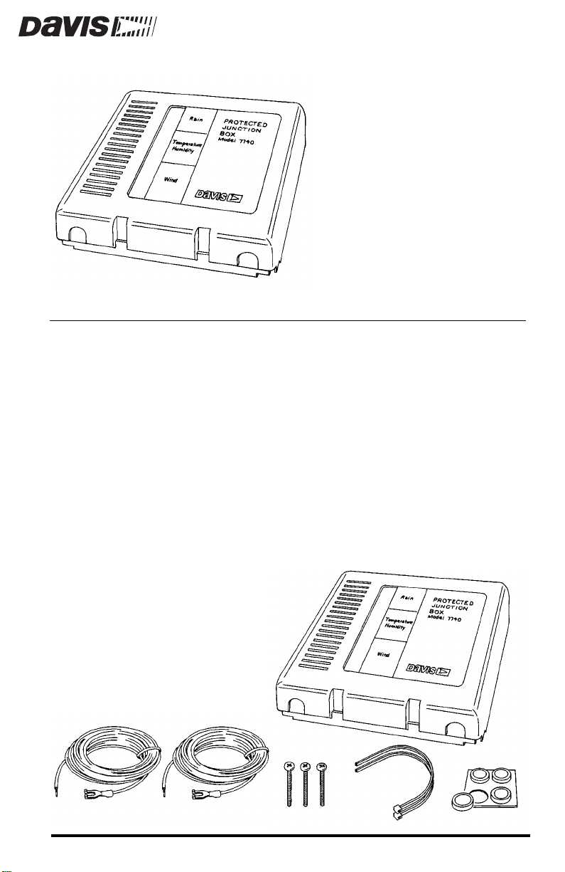
The Protected Junction Box includes the following components. Please make
sure you have all listed components before continuing.
✦
Protected Junction Box
Two 16.5-foot (5 m) Ground
✦
Wires (12 AWG)
✦
Three #6 x 1” (25 mm long)
Self-Threading Screws
Two Cable Ties
✦
✦
Four Adhesive Pads
B
OX
Product #7740
Page 2
OOLS AND MATERIALS NEEDED
T
In addition to the components listed above, you may need some of the following tools and materials. Please be sure you have everything you need before
beginning the installation.
Medium Slotted Screwdriver
✦
✦
Sheet of Small Labels
D
ISCONNECTING
If necessary, consult your weather station manual for instructions on disconnecting the cables from your existing junction box and removing the existing
junction box from its mounting location.
Note: Do not throw away your existing junction box. The surge absorbers in the Protected Junction Box
may “blow” if they absorb a direct or near lightning strike. In this case, you may use your old
junction box to keep the station operating while the Protected Junction Box is repaired (provided
your sensors haven’t “blown” as well).
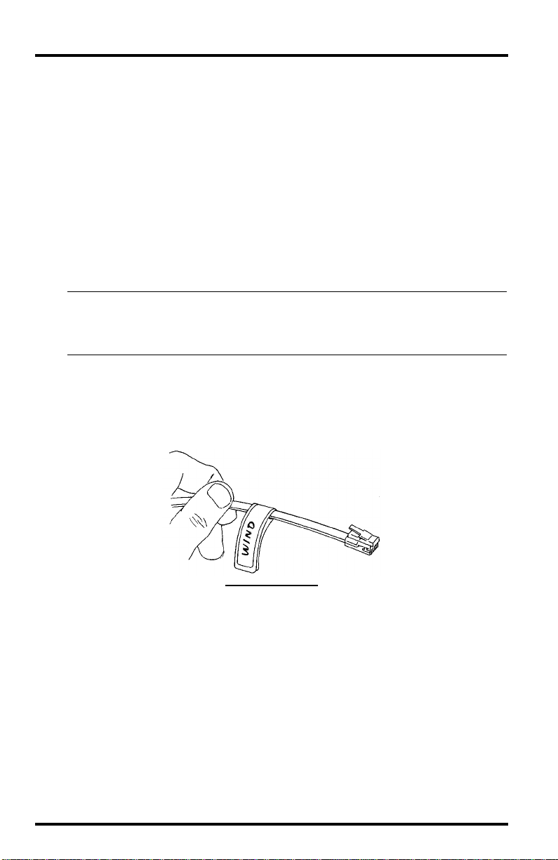
We recommend that you label the end of each cable as you disconnect it. For
example, write “WIND” onto one half of a small label (not provided) and then
wrap that label around the anemometer cable about 3” (75 mm) from the
phone plug. This will help you identify the cables when attaching to the Protected Junction Box.
THE
E
XISTING
L
ABELING
J
UNCTION
Y
OUR
C
ABLES
B
OX
Page 2 Protected Junction Box
Page 3
OUNTING
M
You may mount the Protected Junction Box against a wall or other vertical surface or you may simply set it down on a horizontal surface.
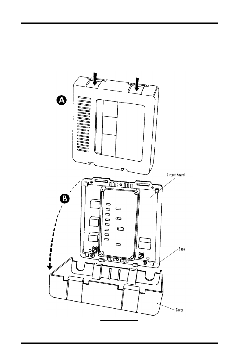
1. Remove the cover from the Protected Junction Box by pushing down on the tabs at the
THE
top until you can remove the tabs from the slots.
ROTECTED
P
UNCTION
J
B
OX
R
Mounting the Protected Junction Box Page 3
EMOVING
THE
C
OVER
Page 4

2. If you plan to mount the Protected Junction Box against a wall or other vertical surface, attach the base to the mounting surface using the #6 x 1” screws. Otherwise,
skip this step.
Use two screws (as pictured below) when attaching to a stud. Use three
screws (as pictured below) in any other case. Tighten the screws until the
base is securely fastened to the mounting surface. Do not overtighten.
A
TTACHING
THE
B
ASE
TO
THE
M
OUNTING
S
URFACE
3. If you plan to place the Protected Junction Box on a horizontal surface, attach one of
the adhesive pads to each of the four raised circles on the underside of the base. Otherwise, skip this step.
A
TTACHING
A
DHESIVE
P
ADS
4. Insert the Rain Collector cable into the connector marked RAIN.
5. Insert the cable from your External Temperature Sensor, External Temperature/
Humidity Sensor, or Stainless Steel Temperature Sensor into the connector marked
TEMP.
6. Insert the anemometer cable into the connector marked WIND.
Page 4 Protected Junction Box
Page 5

7. Insert the junction box cable into the connector marked WEATHER COMPUTER.
The length of cable between the station console and the Protected Junction
Box may be a maximum of 200' (60 m).
C
ONNECTING
THE
C
ABLES
8. If you want to use the Protected Junction Box’s surge suppression capabilities, loosen
the screw in terminal JP1 (the lower left of the circuit board).
See “Surge Protection” on page 7 for more information.
9. Place the spade lug at the end of the ground wire under the screw head.
10.Secure the ground wire by re-tightening the screw in terminal JP1.
11. If you want to use the Protected Junction Box’s RFI protection, repeat steps 8-10 using
the other ground wire and terminal JP2 (the lower right of the circuit board).
See “RFI Filtering” on page 8 for more information.
G
ROUNDING
THE
P
ROTECTED
J
UNCTION
B
OX
Mounting the Protected Junction Box Page 5
Page 6

12. Gather the RAIN, TEMP, and WIND cables and the ground wire from JP1 and secure
them to the cable tie lug using a cable tie.
When tightening the cable tie, make sure the cables are on top of the lug.
S
C
T
ECURING
ABLES
TO
C
ABLE
L
IE
UG
13. Gather the junction box cable and the ground wire from JP2 and secure them to the
cable tie lug using a cable tie.
When tightening the cable tie, make sure the cables are on top of the lug.
Note: Even if you are not using a ground wire at terminal JP2, secure the junction box cable to the
cable tie lug for strain relief.
14. Reattach the Protected Junction Box cover to the base.
Make sure the tabs on top of the cover snap back into their slots, locking the
cover in place.
R
EATTACHING
THE
C
OVER
Page 6 Protected Junction Box
Page 7

ROUNDING
G
Grounding the Protected Junction Box at terminals JP1 and JP2 provides both
surge protection and filtering of radio frequency interference (RFI).
Surge Protection
The Protected Junction Box includes a microgap surge absorber on each sensor
input wire that shunts current pulses to ground. The surge absorbers operate
when the voltage exceeds 200 Volts (the weather station is designed to withstand short pulses at 200 Volts) and can handle current pulses of up to 500
Amps. They provide excellent protection against electrostatic discharge (ESD)
and most secondary surges caused by lightning. Surge absorbers will not, however, withstand a direct or near lightning strike.
Note: You may see blue flashes inside a surge absorber when they are operating. This is a normal indi-
If the current load is too great, surge absorbers will “blow” (when “blown,”
they will appear black inside). It is possible, in extreme cases, for an absorber to
shatter, so it is important that you keep the clear plastic cover on the Protected
Junction Box at all times. Unless it has been otherwise damaged, the Protected
Junction Box will continue to function normally when surge absorbers “blow,”
however the surge protection will no longer be present.
In order for surge protection to be effective, you must connect the Protected
Junction Box to an earth ground from terminal JP1. This connection should use
as heavy and as short a wire as possible. The 16.5-foot (5 m) 12AWG wire provided works well. Connect one end of the ground wire to terminal JP1 and connect the other end to a suitable earth ground. The best earth ground is a copper
rod driven into the earth. Alternatively, you may connect to a grounded metal
cold water pipe.
THE
cation that surges are being absorbed.
ROTECTED
P
UNCTION
J
B
OX
Grounding the Protected Junction Box Page 7
Page 8

RFI Filtering
The Protected Junction Box includes built-in RFI filtering capabilities. In order
for these capabilities to be most effective, however, you must connect the Protected Junction Box to an earth ground from terminal JP2. This connection
should use as heavy and as short a wire as possible. The 16.5-foot (5 m) 12AWG
wire provided works well. Connect one end of the ground wire to terminal JP2
and connect the other end to a suitable earth ground. The best earth ground is a
copper rod driven into the earth. Alternatively, you may connect to a grounded
metal cold water pipe.
Be aware that connecting JP2 to ground can cause measurement errors (especially in temperature) in some cases. To correct the problem, you should isolate
the weather station from any other connections to ground:
Use an ungrounded power adapter for the weather station.
✦
Use a Link Isolator (#7764) to isolate the weather station from the computer’s
✦
ground.
✦
If RFI is not a problem in your installation, you may omit grounding the Protected
Junction Box at terminal JP2.
M
AINTENANCE
Y ou should periodically look at the sur ge absorbers to insur e that none of them
has “blown” (turned black inside). If an absorber blows you may obtain a
replacement part from Davis or send the Protected Junction Box back for
repairs. Call the service department before returning the Protected Junction
Box. While your Protected Junction Box is being repaired, you may use your
old junction box to keep the weather station operating.
I
NSTRUCTIONS
Product Number: 7740
Davis Instruments Part Number: 7395-098
Protected Junction Box
Rev. B Manual (7/7/99)
This product complies with the essential protection requirements of the EC EMC
Directive 89/336/EC.
© Davis Instruments Corp, 1997. All rights reserved.
 Loading...