

Page 1

#462
Little Brother to the HAPPY TROLLER
®
For Outboard Motors Up To and Including 25 Horsepower
INSTALLATION INSTRUCTIONS
Step 1: Remove the four 1/4" (6.5 mm) mounting bolts, wash-
ers, and nuts from package and retain for installation.
Step 2: Pull control handle and allow troll plate to move down
into troll position. CAUTION: Troller is spring
loaded; don’t pinch your fingers.
Step 3: Locate the anti-cavitation plate on your motor or out-
drive. It’s the wide horizontal plate which extends just
above the propeller. Always select the flat side of the
anti-cavitation plate to mount the Lil’ Fella. Where
possible, mount the unit on the underside of the cavitation plate.
Step 4: With the troller plate locked in the troll (down) posi-
tion, place Troller on the anti-cavitation plate and
move as far forward as possible without causing interference with the Troller’s operating mechanism. Prior
to drilling, pull cord making sure the locking bar
moves all the way forward to the end of its slots, without any interference with the anti-cavitation plate,
fins, or ridges. Square up the Troller and use two
small “C” clamps to hold it securely in place for
drilling. Note: The two forward and two stern holes
are to be used for most outboard motor installations.
Step 5: Using a 1/4" (6.5 mm) drill bit, place drill in existing
hole in mounting plate. Using the hole as a drill guide
and keeping the drill square, drill straight through the
anti-cavitation plate (this plate is a solid casting and
no water jacket is involved). Before proceeding to the
next hole, insert a 1/4" (6.5 mm) bolt in the hole just
drilled. Position head of bolt on the mount plate side
and lightly tighten the nut and washer on the anticavitation plate side. Repeat this procedure for the
three remaining holes. Tighten all four bolts, but be
careful not to over-tighten.
If for some reason the hole pattern in the Lil’ Fella
does not work for your anti-cavitation plate, feel free
to drill new holes in the Lil’ Fella to obtain the best
possible fit and maximum strength. Do not attempt
to modify your anti-cavitation plate.
Step 6: Uncoil Troller control cord and tie off securely in a
convenient location, preferably in the center of the
stern of your boat. CAUTION: Allow sufficient slack
in the control cord to prevent accidental operation of the Troller during full turns of the boat.
Such inadvertent operation, going undetected,
could cause damage to the Troller or anti-cavitation plate. Excess slack may foul in the propeller,
also resulting in damage.
OPERATING INSTRUCTIONS
Always lubricate moving parts before each day’s
use.
Step 1: We recommend keeping your Troller in the troll
(down) position for storage and trailering.
Step 2: Before launching your boat, make certain the troll
plate is in the cruise (up) position. To accomplish this,
pull the control lever forward with one hand and lift up
the troll plate with the other hand. When troll plate is
against the stop (horizontal), release the control lever
and the Troller will lock in the cruise/travel position.
You are now ready to launch your boat. After launch-
ing, visually check to make sure the Troller is in
the cruise (up) position before getting underway.
Step 3: Ready to troll?
(a). Bring boat to a full stop.
(b). Place motor in neutral.
(c). Pull control cord to end of its travel and hold for a
few seconds while the springs move troll plate to the
locked down position, then release.
(d). Shift to forward gear and slowly adjust throttle for
proper trolling speed. Troll speed will normally be 50
to 75 RPM above dead idle. Caution: Damage will
occur if sudden throttle is applied or engine is
operated over 1200 RPM while in trolling position.
Step 4: Finished trolling?
(a). Reduce speed to dead idle.
(b). While still in forward gear, pull control cord. You
should feel a sudden movement forward as the troll
plate is released.
(c). Stop and visually check to make sure the troll
plate is released (locked in the up position).
(d). Slowly proceed to cruising speed. If drag is felt,
stop immediately and check Troller position.
(e). Visually check one more time. If in locked up
position, you may proceed to full power.
Be sure to carefully follow these instructions. Neither the manufacturer or re-seller are responsible for the correction of any
damage incurred to the boat, engine, anti-cavitation plate,
lower drive, propeller, or the Troller.
Save These Instructions
Page 2
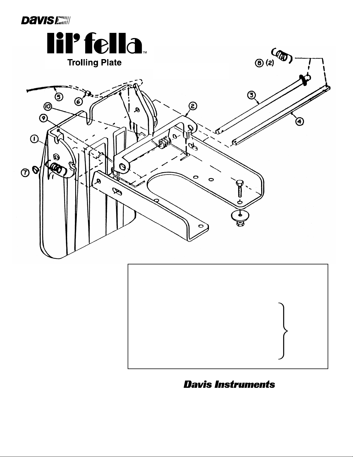
Part Order Description Qty.
Number per Unit
1 R462A Backplate 1
2 R462B Control Arm with Cord and Swedge 1
3 Pivot Rod
4 Locking Bar
5, 6 Control Cord and Swedge
7 Ring Pin,
stainless steel
8 Locking Bar Springs,
stainless steel (2)
9 Lowering Spring, LH
stainless steel
10 Lowering Spring, RH
stainless steel
PARTS LIST
Lil’ Fella™replacement parts may be
available through your local dealer. If not,
you may order directly from Davis
Instruments Corporation.
Lil’ Fella
™
Parts Kit,
order number
R462C
3465 Diablo Avenue, Hayward, CA 94545, U.S.A.
Phone (510) 732-9229 • Fax (510) 732-9188
info@davisnet.com
For information about our other fine products, visit www.davisnet.com
ONE-YEAR WARRANTY
We warrant our products to be free of defects
in material and workmanship for one year
from the date of original purchase. Write for
full warranty details.
462_Inst.pdf April 2006
 Loading...