

Page 1
NTERFACE
I
C
ABLE
M
ODULE
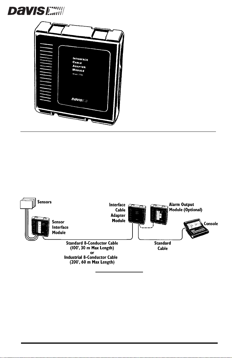
The Interface Cable Adapter Module (ICAM) has two basic uses. First, it
enables you to run shielded cable between the industrial sensor interface
module (SIM) and the weather station console. The ICAM provides the means
of transition from shielded cable to the standard cable that plugs into the
console. Second, when the circuits being controlled by the Alarm Output
Module (AOM) are closer to the console than to the SIM, the ICAM enables you
to plug the AOM and the console into the ICAM and run standard or shielded
8-conductor cable from the ICAM to the SIM.
A
DAPTER
T
ICAM I
YPICAL
This instruction manual takes you step-by-step through the process requir ed to
connect and mount your ICAM. Please take the time to read this manual before
beginning the process.
NSTALLATION
Product # 7760
Page 2
OMPONENTS
C
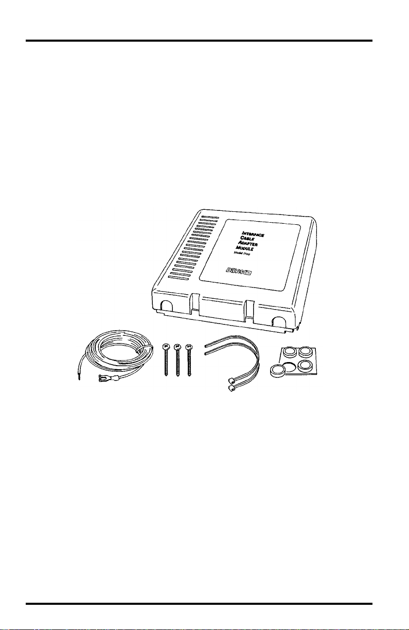
The ICAM includes the following components. Please make sure you have all
listed components before continuing.
Interface Cable Adapter Module
✦
16.5-foot (5 m) Ground Wire
✦
(12 AWG)
✦
Three #6 x 1” (25 mm long)
Self-Threading Screws
✦
Two Cable Ties
✦
Four Adhesive Pads
T
OOLS AND MATERIALS NEEDED
In addition to the components listed above, you may need some of the following tools and materials. Please be sure you have everything you need before
beginning the installation.
Medium Phillips Screwdriver
✦
Small Slotted Screwdriver
✦
✦
Wire Cutter
Wire Stripper or Knife
✦
Modular Connector Installation Tool
✦
Page 2 Interface Cable Adapter Module
Page 3
OUNTING
M
You may mount the ICAM against a wall or other vertical surface or you may
simply set it down on a horizontal surface.
1. Before installing, consult your system installation manual for instructions on labeling
cables.
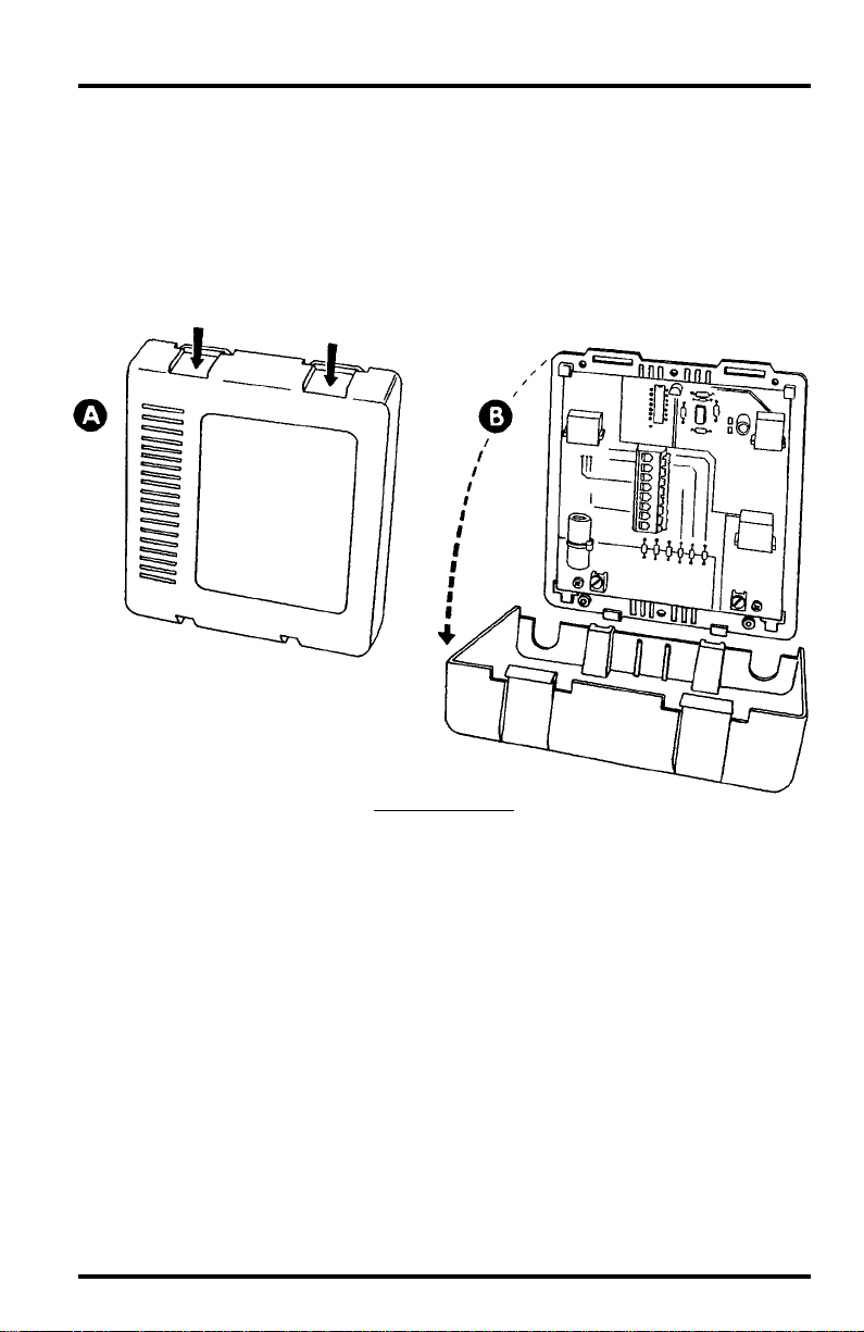
2. Remove the cover from the ICAM by pushing down on the tabs at the top until you can
remove the tabs from the slots.
THE
NTERFACE
I
C
ABLE
DAPTER
A
M
ODULE
R
Mounting the Interface Cable Adapter Module Page 3
EMOVING
THE
C
OVER
Page 4

3. If you plan to mount the ICAM against a wall or other vertical surface, attach the base
to the mounting surface using the #6 x 1” screws. Otherwise, skip this step.
Use two screws (as pictured below) when attaching to a stud. Use three
screws (as pictured below) in any other case. Tighten the screws until the
base is securely fastened to the mounting surface. Do not overtighten.
A
TTACHING
THE
B
ASE
M
TO
THE
OUNTING
S
URFACE
4. If you plan to place the ICAM on a horizontal surface, attach an adhesive pad to each
of the four raised circles on the underside of the base. Otherwise, skip this step.
A
TTACHING
A
DHESIVE
P
ADS
Page 4 Interface Cable Adapter Module
Page 5

5. Attach cables to the ICAM as shown below.
C
ONNECTING
If connecting to the AOM from the ICAM, connect one end of the
✦
THE
AOM cable to connector S6.
✦
Attach one end of the standard 8-conductor cable which runs from
the ICAM to the console to connector S7 on the ICAM.
If running shielded 8-conductor cable from the SIM to the ICAM,
✦
strip 4” (10 cm) of cable jacket and shield (the grey outer covering
and foil-like inner covering) and strip 5/16” (8 mm) of insulation
(the colored covering) from each wire. Feed the wires through the
ferrite bead and insert into terminal block connector C2 according to
the wire colors printed on the circuit board. (To place wires into a
terminal, use a small screwdriver to push down on the lever next to
the terminal, insert the exposed wire into the opening created, and
release the lever . When you r elease the lever, the wire(s) will be held
in place.) Connect the bare drain wire to the Shield terminal (JP2).
Cut off any excess drain wire.
If running standard 8-conductor cable from the SIM to the ICAM,
✦
you may connect to either modular connector C2 or terminal block
connector C2 (continued on next page).
C
ABLES
Mounting the Interface Cable Adapter Module Page 5
Page 6

If you wish to connect to the terminal block connector, you will need
to determine the wire assignments for the terminal block. To do this,
hold the standard cable, latch lever upward, facing the terminal
block, as shown in the illustration below. The wires in the cable are
now in the same sequence as the terminals. For future reference,
write the wire colors into the spaces provided below if they do not
match the colors marked on the circuit board.
D
ETERMINING
W
IRE
A
SSIGNMENTS
To connect standard cable, first strip 4” (10 cm) of cable jacket (the
grey outer covering) and strip 5/16” (8 mm) of insulation (the
colored covering) from each wire. Run the wires through the ferrite
bead. You may then attach a new RJ45 connector and plug into the
modular connector C2. Or you may connect to the terminal block
connector C2. T o place wires into a terminal, use a small scr ewdriver
to push down on the lever next to the terminal, insert the exposed
wire into the opening created, and release the lever. When you
release the lever, the wire(s) will be held in place.
Page 6 Interface Cable Adapter Module
Page 7

6. For most effective RFI (noise) filtering, connect the spade lug on the ground wire to
the Shield terminal (JP2) and connect the other end of the ground wire to ground. In
most installations, it will be sufficient to use a short piece of the ground wire to connect the Shield terminal (JP2) to the Ground terminal (JP1). In this case, no additional
ground is required.
Choose one of the two grounding options. Do not run one ground wire
from JP1 to JP2 and another from JP2 to ground.
G
ROUNDING
THE
ICAM
7. Gather the cables connected on the left of the ICAM (including the ground wire, if
used) and secure them to the cable tie lug using a cable tie.
Even if you have only one cable, secure it to provide strain relief. When
tightening the cable tie, make sure the cables are on top of the lug.
S
C
T
ECURING
ABLES
TO
L
C
ABLE
IE
UG
8. Gather the cables connected on the right of the ICAM and secure them to the cable tie
lug using a cable tie.
Even if you have only one cable, secure it to provide strain relief. When
tightening the cable tie, make sure the cable is on top of the lug.
Mounting the Interface Cable Adapter Module Page 7
Page 8

9. Reattach the cover by putting the cover into place (as shown below) and pushing it
onto the base until the tabs on top of the cover snap back into their slots.
Make sure to route the cables out the bottom of the ICAM as shown below.
R
EATTACHING
THE
C
OVER
Product Number: 7760
Davis Instruments Part Number: 7395-109
Interface Cable Adapter Module
Rev. A Manual (7/7/99)
This product complies with the essential protection requirements of the EC EMC
Directive 89/336/EC.
© Davis Instruments Corp. 1996. All rights reserved.
 Loading...