

Page 1
ROUNDING
G
K
IT
Many of our products require a proper ground in order to function properly.
For situations where a proper ground is not available, all you need to do is
drive the grounding rod into the earth to create a ground for any of our products. In some cases, more than one ground rod may be required to meet specifications. Check your local codes to make sure that the grounding rod will
provide a suitable ground for your location.
OMPONENTS
C
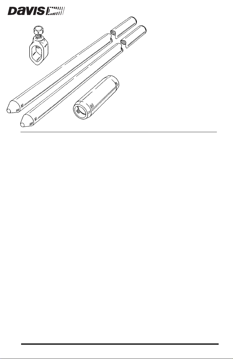
The Grounding Kit includes the following. Please make sure you have everything you need before beginning.
✦
2 Copper-plated Rods 5/8” (1.5 cm) diameter x 32 inches (81 cm)
Coupler
✦
Wire Clamp
✦
OOL AND MATERIALS NEEDED
T
You will need some of the following tools and materials.
Shovel
✦
✦
Heavy-duty Hammer, 2.5-pound (1 kg) or heavier
✦
Wrench
Wire Stripper or Knife
✦
✦
Ladder
Page 1
Page 2
ONNECTING
C
THE
R
OD
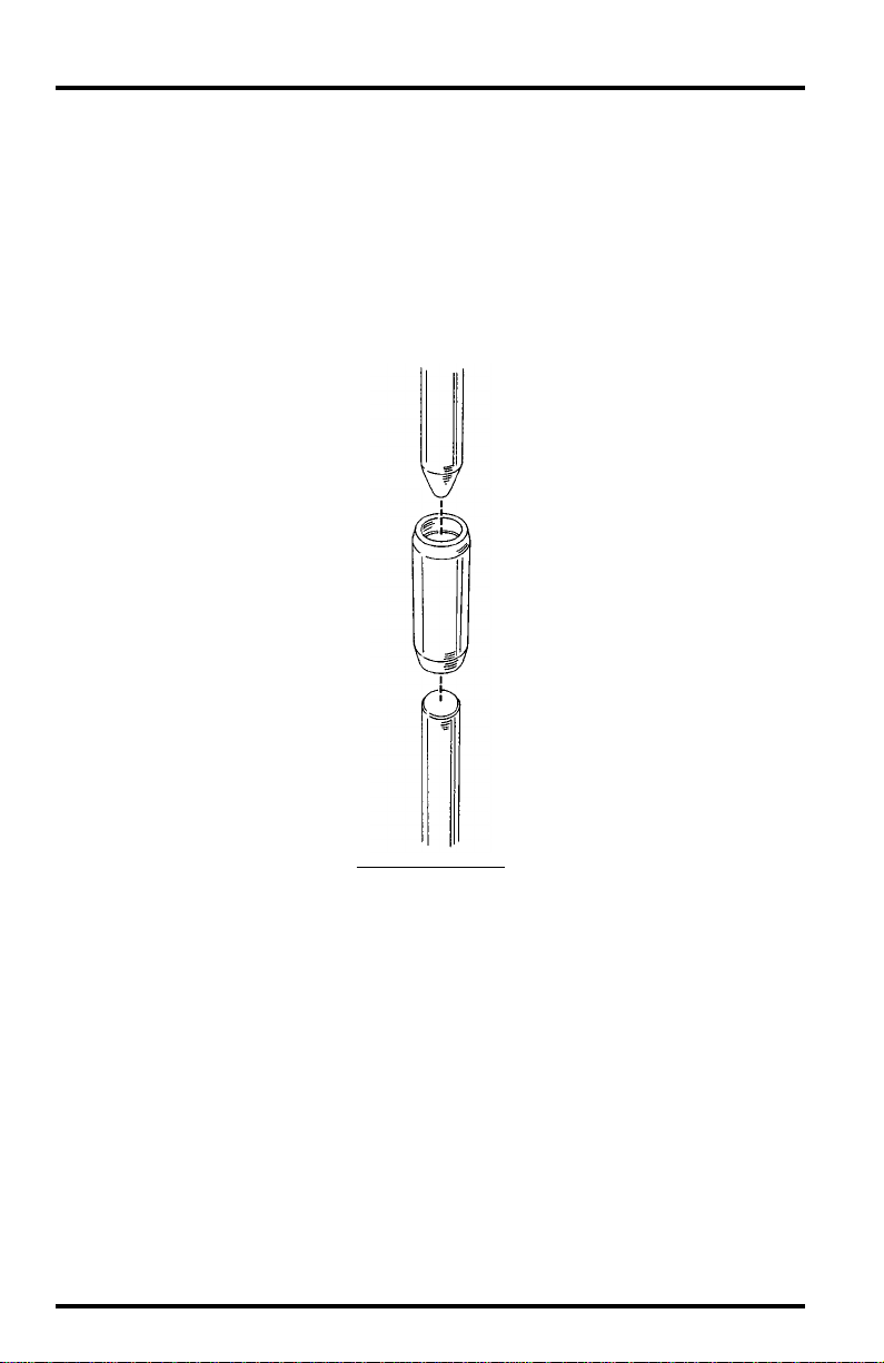
The rod itself ships in two pieces. You must connect them to create a suitably
long grounding rod. Be aware, however, that pounding the top of the rod may
make it impossible to fit the coupler (or the wire clamp) over the top of the rod.
Make sure you put the coupler (and wire clamp) onto the rod before you begin
pounding. Connect the two halves of the rod, using the provided coupler, as
shown below. Note that the bottom of the assembled rod (the end which goes
into the ground) should have a point and the top of the assembled rod should
be flat.
C
ONNECTING
THE
R
OD
Page 2 Grounding Kit
Page 3

URYING
B
THE
T o cr eate a pr oper gr ound, you need to drive the r od into the gr ound. Be awar e
that pounding the top of the rod may make it impossible to fit the coupler and/
or the wire clamp over the top of the rod. Make sure you put the coupler and
wire clamp onto the rod before you begin pounding. You can secure the ground
wires to the rod after you’ve driven the rod into the ground.
The height of the grounding rod, when fully assembled, may make it difficult
to pound the top. You might want to stand on a ladder when pounding or you
might want to place the coupler onto the bottom rod (flat side into the coupler)
and pound the top of the coupler to drive the rod into the ground a little way.
Then place the second rod into the coupler (point side into the coupler) and
continue driving the assembled rod into the ground as described below.
You may simply place the rod, point side down, in the desired location and
drive it into the ground until only 4-5 inches (10-12 cm) of the rod remains visible. Or, you may dig a hole about 6” (15 cm) deep and 6“ (15 cm) wide into
which you will drive the rod. Place the rod, point side down, in the desired
location (inside the hole) and drive it into the ground until only 4-5 inches (1012 cm) of the rod remains visible. Attach ground wires to the rod at this point.
The advantage of digging the hole is that you may partially fill in the hole once
you have attached ground wires to the rod, thus making less of the rod visible
above ground.
ible above ground.
OD
R
However, you should always leave some portion of the rod vis-
P
B
URIED
R
OD
ARTIALLY
Burying the Rod Page 3
Page 4
TTACHING
A
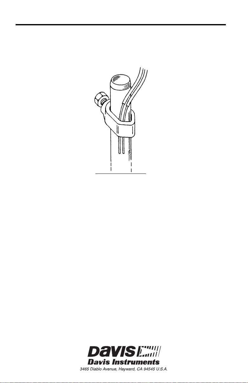
To attach ground wires to the rod, strip away 1 inch (3 cm) of insulation, insert
the wires between the wire clamp and the rod, and secure the wir es in place by
tightening the wire clamp as shown below.
ROUND
G
W
IRES
A
TTACHING
G
ROUND
W
IRES
Product Number: 7780
Davis Instruments Part Number: 7395-083
Grounding Kit
Rev. B Manual (7/7/99)
This product complies with the essential protection requirements of the EC EMC
Directive 89/336/EC.
© Davis Instruments Corp. 1997. All rights reserved.
 Loading...