

Page 1

USER
MANUAL
Ethernet
Gateway
and Node
Product number 6810 and 6805
R
Davis Instruments, 3465 Diablo Avenue, Hayward, CA 94545-2778 U.S.A. • 510-732-9229 • www.davisinstruments.com
Page 2

FCC Part 15 Class B Registration Warning
This equipment has been tested and found to comply with the limits for a Class B digital
device, pursuant to Part 15 of the FCC Rules. These limits are designed to provide
equipment generates, uses, and can radiate radio frequency energy and, if not installed and used in
accordance with the instructions, may cause harmful interference to radio communications.
However, there is no guarantee that interference will not occur in a particular installation.
This device complies with part 15 of the FCC Rules. Operation is subject to the following two
conditions: (1) this device may not cause harmful interference, and (2) this device must accept any
interference, including interference received, including inference that may cause undesired operation.
This device complies with Industry Canada license-exempt RSS standard(s). Operation is subject to
the following two conditions: (1) this device may not cause interference, and (2) this device must
accept any interference, including interference that may cause undesired operation of the device.
Le présent appareil est conforme aux CNR d'Industrie Canada applicables aux appareils radio
exempts de licence. L'exploitation est autorisée aux deux conditions suivantes: (1) l'appareil ne doit
pas produire de brouillage, et (2) l'appareil doit accepter tout brouillage radioelectrique subi, même si
le brouillage est susceptible d'en compromettre le fonctionnement
Innovation, Science and Economic Development Canada ICES-003 Compliance Label: CAN ICES-3
(B)/NMB-3(B)
Changes or modification not expressly approved in writing by Davis Instruments may void the warranty
and void the user's authority to operate this equipment.
FCC ID: IR2DWW6805 IC: 3788A-6805
Contains: FCCID: 2AC7Z-ESPWROOM02 IC: 21098-ESPWROOM02
The antenna used for this transmitter must be installed to provide a separation distance of at least 20
cm from all persons and must not be co-located or operating in conjunction with any other antenna or
transmitter.
If this equipment does cause harmful interference to radio or television reception, which can be
determined by turning the equipment on and off, the user is encouraged to try to correct the
interference by one or more of the following measures:
• Reorient or relocate the receiving antenna.
• Increase the separation between the equipment and receiver.
• Connect the equipment into an outlet on a circuit different from that to which the receiver is
• Consult the dealer or an experienced radio/TV technician for help.
This radio transmitter 3788A-6805 has been approved by Innovation, Science and Economic
Development Canada to operate with the antenna types listed below, with the maximum permissible
gain indicated. Antenna types not included in this list that have a gain greater than the maximum gain
indicated for any type listed are strictly prohibited for use with this device.The following antennas are
permissible to use with this product:
AMXF-9092-8 8dBi 50 Ohms
AMXF-9092-6 6dBi 50 Ohms
AMXF-9092-5 5dBi 50 Ohms
reasonable protection against harmful interference in a residential installation. This
connected.
EC-Declaration of Conformity
Directive 2014/53/EU (RED Directive)
Manufacturer/responsible person: Davis Instruments
Declares that the products: 6805EU, 6805 UK
Comply with the essential requirements of 2014/53/EU, if used for its intended use. The complete Declaration of Conformity is on our website at https://www.davisinstruments.com/legal.
The technical documentation relevant to the above equipment will be held at: Davis Instruments at 3465 Diablo
Ave, Hayward CA 94545
Power Output: see page 18: Specifications
0
Compliance Engineer
3465 Diablo Ave., Hayward, CA 94545 USA
Page 3
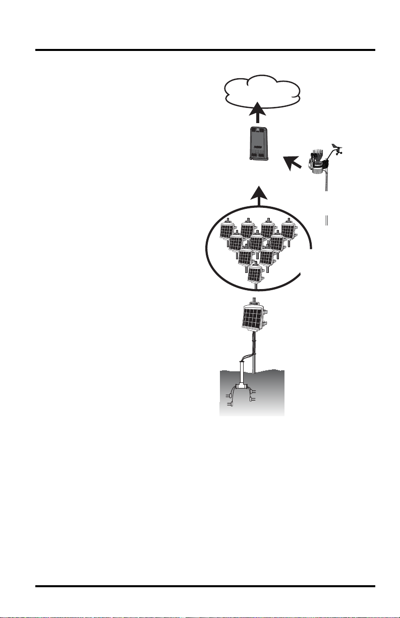
Welcome to Your EnviroMonitor System
An EnviroMonitor System
includes a Gateway and a
number of Nodes, each with up
to four sensors that form an
advanced mesh network
operating at 902 - 928 MHz (868
MHz in the EU). The Nodes
transmit the sensor data to a
“mesh parent,” either the
Gateway or another Node. The
Gateway then sends the data via
ethernet connection to
WeatherLink.com.
EnviroMonitor can be
customized for different sized
installations. Each Gateway can
receive 20 or more Nodes.
Additional Gateways can be
added to your account to receive
data from another set of Nodes.
A Davis wireless or cabled
GroWeather Sensor Suite can
also be plugged into the
Gateway.
This manual will show you how
to set up both the EnviroMonitor
Gateway and Nodes. If you are
just installing a Node and have
already installed the Gateway,
you can skip to page 9:
Nodes and Sensors
Set Up
.
WeatherLink.com
1 Gateway
0-4 Sensors
per Node
Wireless or cabled
GroWeather ISS
(optional)
20+
Nodes
per
Gateway
The steps for setting up your EnviroMonitor system:
1. Plan: What sensors do you need and where? Decide where you will install the
Gateway and Nodes. See page 2:
2. Power up your Gateway. See page 6:
Planning Your System.
Power-up and Connect your Gateway.
3. Connect your Gateway to WeatherLink.com with the EnviroMonitor app.
4. Power up the Node. See page 10:
Power-up and Connect the Node.
5. Connect the Node to the Gateway with the EnviroMonitor app.
6. Mount the Node. See page 13:
Mount the Node.
7. Add and Install the sensors with the EnviroMonitor app.
1
Page 4
Planning Your System
Before installation, plan your system. After determining which sensors you want and
where you want to install them, make sure you have the correct number of Nodes to
support those sensors.
The maximum distance between two Nodes and a Gateway and a Node will vary
depending on many factors including environment, height, terrain and RF noise.
To get optimal transmission range:
• Ideally, locate the devices with unobstructed lines of sight between them. A large
hill or large metal barrier will block signals. If transmitting under a canopy or in
an orchard, range will be reduced.
• Mount the devices as high above the ground or the highest crop height as
possible. The higher they are mounted, the longer the transmission distance, as
shown below.
• The Gateway should be placed in a window or as close to the outside of the
building and as close to the Nodes as possible; higher is better.
300 - 500 ft
90 -150 m
Orchard, under canopy
6 feet
1.8 m
Line of sight, above highest
crop height or open eld
2400 ft
730 m
4 feet
1.2 m
3 feet
1 m
2000 ft
600 m
Line of sight, above highest
crop height or open eld
4000 ft
1200 m
10 feet
3 m
Line of sight, above highest
crop height or open eld
6 feet
1.8 m
2
Page 5
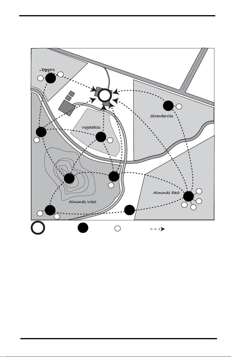
Make a Sketch
It is helpful to make a sketch of your installation to get an idea of where the
Gateway and Nodes should go.
SAMPLE FARM
Peppers
S
N
S
N
Davis Rd.
G
S
N
Strawberries
Vegetables
N
S
N
Almonds West
N
N
S
S
G
G
Gateway Node Sensor Transmission Mesh
N
N
N
S
Diablo Creek
N
S
Almonds East
N
S
Hwy. 10
N
S
S
S
S
3
Page 6

Siting the Nodes
• Ideally, the mesh network will be most effective at “self healing” any
temporarily impaired transmission paths if each Node has more than one way
to reach the Gateway. While the system is designed to handle a mesh, a “star”
or nodes in single lines, it is a good idea whenever possible to site each node
so that it is within transmission distance of either two (or more) other Nodes,
or the Gateway and another Node. A Node can even be installed simply to
transmit data from more distant Nodes to the Gateway, without any sensors
installed in it. By planning the system’s “transmission mesh,” data can be
relayed in from the most remote corner of your installation.
The best installations allow Nodes to
transmit to more than one Node or to
a Node or Nodes and the Gateway.
• Nodes can also be used to transmit data around or over obstacles, such as hills.
Get around an obstruction by using a Node with no sensors as a relay.
4
Page 7

Set up your Gateway
Contents of Gateway
Blue LED
Capacitive
Touchpad
Ethernet Cable
Ethernet Gateway
Ethernet Gateway Requirements & Tools
• Wi-Fi or router Ethernet internet connection
• Wi-Fi password
• Smartphone
• 4 AA batteries (not included)
AC Adapter
5
Page 8
Power-up and Connect your Gateway
AAA
A
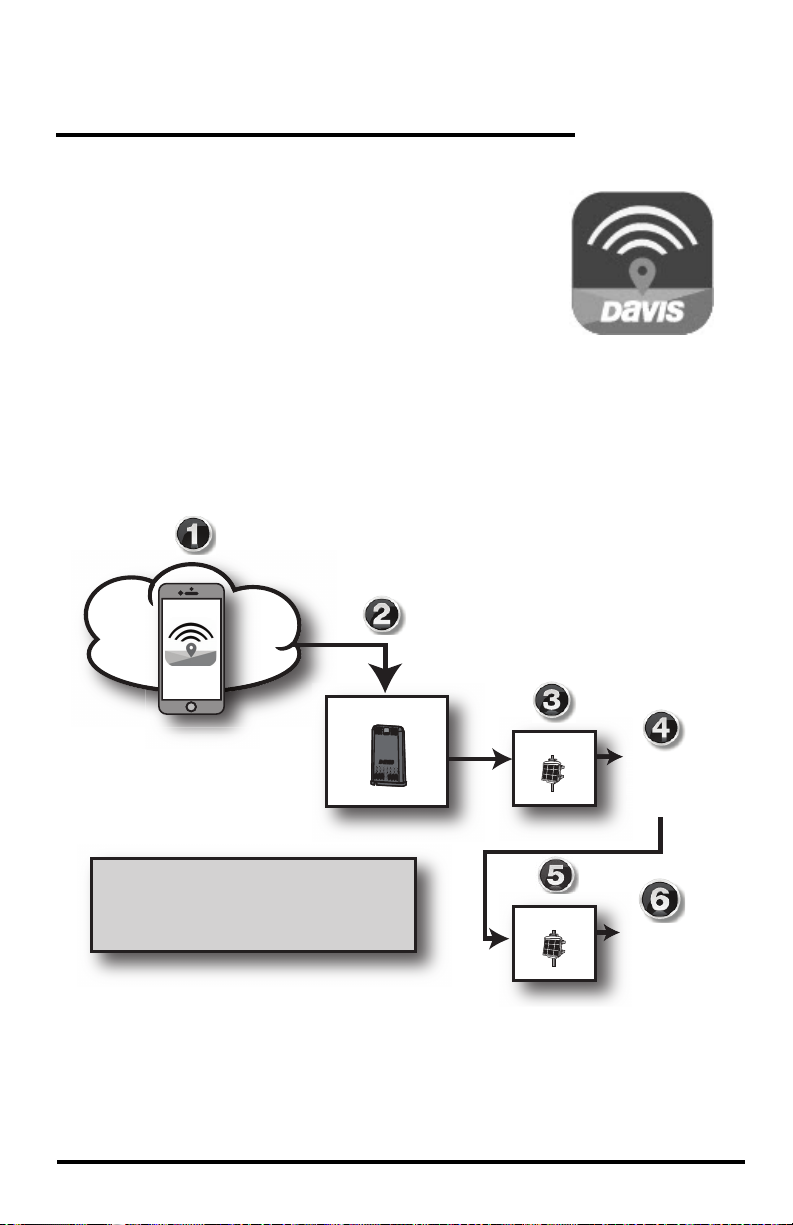
Install the EnviroMonitor App
1. Install the EnviroMonitor app on your Smartphone.
Find the app by searching for the Davis
EnviroMonitor app in the iOS App Store or Google
Play Store.
The EnviroMonitor app will guide you through
creating an account on WeatherLink.com, adding the
Gateway, adding Nodes to the Gateway, and adding
sensors to the Node.
Add Gateway
Open the App to create your
he App to create
account on WeatherLink.com
EnviroMonitor App:
Guides you through these steps
EnviroMonitor App
Add Node 1
Add Node 2
Add Sensor 1
Add Sensor 2
Add Sensor 3
Add Sensor 4
Add Sensor 1
Add Sensor 2
Add Sensor 3
Add Sensor 4
6
Page 9

Install the WeatherLink App and Create Your Account
2. Install the WeatherLink mobile app on your smartphone. Find
the app by searching for the Davis WeatherLink app in the iOS
App Store or Google Play Store.
3. In the app, create your account on WeatherLink.com.
Note: You will use the user name and password you have set up to access your page on
WeatherLink.com from your computer as well. You will only have to enter your name
and password the first time you open the app unless you log out.
Power Up and Connect Your Gateway
1. Plug the AC adapter into the socket on the
bottom of the Gateway and plug the adapter
into the wall.
AC Adapter
Socket
There are cable channels to the front and
back, as well as the side, in which to run the
cable.
Cable
Channels
Note: The Gateway is powered by AC power with battery backup. AC power is required;
it cannot be set up or run on batteries alone. It is highly recommended that you
install batteries to prevent loss of data if AC power is lost. If AC power is lost, the
Gateway will stop trying to communicate with your network, but it will continue to
receive sensor data and store it. When AC power is resumed, it will reconnect with
the network and send the records it stored during the outage to your database on the
WeatherLink cloud.
2. Install the batteries. Open the battery
compartment on the bottom of the
Gateway. To do this, slide the cover
forward then lift up.
Insert
4 AA
Batteries
To open,
slide cover
forward
then up.
Insert four AA batteries, making sure
you insert them with the positive and
negative ends oriented as indicated on
the underside of the battery
compartment cover.
7
Page 10

3. Plug the included Ethernet cable into the
socket on the Gateway. Connect the other end
of the cable to your router. You will see green
and amber lights when the connection has
been established.
4. The blue LED light will begin flashing
indicating that the device is ready to connect
Ethernet
Cable
Socket
to the smartphone app.
Tip: The device will “go to sleep” and the blue LED will turn off if you don’t connect the
device within a few minutes. You can “wake it up” when you are ready to proceed by
touching the capacitive touch pad. (See the image on page 1.)
Connect the Gateway to WeatherLink.com
1. Make sure the Bluetooth function on your smartphone is on.
2. Open the EnviroMonitor app and choose Sign Up to create an account, or Log
in if you have already created an account
3. Tap Add Gateway.
4. Bring the phone close to the Gateway.
5. If a message appears that an upgrade has been detected, select Upgrade.
Upgrading can take several minutes.
Tip: The blue LED flashes to show that the Gateway’s BLE is on. If it is not flashing,
press the recessed touch pads. See the illustration on page 5: Contents of
Gateway for the location of the recessed touch pads.
6. The LED will turn solid blue when the Gateway has successfully connected to
your smartphone.
7. Once connected, enter a name for this Gateway. Choose a name based on the
use or location so you can easily identify this Gateway if you install others.
8. Follow the prompts to finish adding the Gateway.
9. Once done, you will be prompted to add a Node. Before adding a Node,
however, you should mount the Gateway.
Add a GroWeather Integrated Sensor Suite (optional)
You can add a cabled or wireless Vantage Pro2 integrated sensor suite (ISS), such
as GroWeather (product number 6820 or 6820C), to your system, which will
report rain, wind, temperature, humidity and solar radiation data to the Gateway.
8
Page 11

Set Up Nodes and Sensors
Contents of Node
Rechargable
Lithium Battery
Compartment
(battery in
hardware kit)
Lithium
Battery
Battery
Compartment
Door
D-Cell Battery
Compartment
(batteries not included)
Hardware Kit
Solar Panel Jack
Solar Panel Cable
Door Tabs
Sensor
Ports
Bluetooth
status LED
Mesh
status LED
Mesh
Antenna
U-Bolts
1/4" Lock Washers
1/4" Hex Nuts
Backing Plates
Green 6-Wire
Sensor Connectors
Cable Ties
Adhesive
Mounts
Precision Screwdriver
1/4" x 1 1/4"
Lag Screws
#6 x 3/8 Screws
(disregard)
9
Page 12

Requirements & Tools for Installation of Nodes and Sen-
A
A
A
A
sors
• Included precision/miniature slotted screwdriver; ideal
size: 2.5 mm or 3/32”; see actual size image of screw
head and screwdriver blade at right.
• Four D-cell batteries
• Smartphone with EnviroMonitor app installed. See page 6:
EnviroMonitor App
.
Install the
• Wire cutter/stripper and wrench
• Mounting pole or post
Note: You should install Nodes starting with the Node that will be closest to Gateway, then
working outward to the Node furthest from Gateway. This allows each Node to
establish a connection with the Gateway or a Node that has already been installed.
Power-up and Connect the Node
Make sure the EnviroMonitor app has been installed on the smartphone you will
be using to install the Node. It will guide you through adding Nodes to the
Gateway that has already been installed.
Add Gateway
Open the App to create your
he App to create
account on WeatherLink.com
Add Node 1
EnviroMonitor App:
Guides you through these steps
Add Node 2
Power Up the Node: See illustration on page 9: Contents of Node.
1. Install 4 D-cell batteries according to the + and - marks in the battery
compartment. The Node will power up. The mesh status LED will indicate
connection.
IMPORTANT: Install the D-cell batteries FIRST. Make sure they are firmly installed and not
tilted outward.
2. Remove the battery pull tab from the factory-installed lithium battery.
10
Add Sensor 1
Add Sensor 2
Add Sensor 3
Add Sensor 4
Add Sensor 1
Add Sensor 2
Add Sensor 3
Add Sensor 4
Page 13

3. Plug in the solar panel cable.
Connect Node to Gateway
1. Take the Node and smartphone to the general location in which you wish to
install your Node. Make sure the phone’s Bluetooth is on.
2. Open the app on the smartphone.
3. Open the door of the Node. (This turns the Node’s Bluetooth on.) The
Bluetooth status LED will blink blue. See the illustration on page 9:
of Node
.
Contents
4. In the app, select the Gateway to which this Node will send its data.
5. Tap Add Node.
6. Bring the phone close to the Node.
7. Follow the prompts in the app as it finds the Node and connects it to the
Gateway. This transmits the Gateway’s identifying information to the Node
and allows its data to be received by the Gateway. Having specific
identification for each Gateway/Node pair allows you to have multiple
Gateways without cross transmission.
Using the app, you will be see this Node’s serial number appear on the list for
the Gateway.
You will know the Node has found its “mesh parent” (a Gateway or another
Node) when you see the Bluetooth status LED go solid blue. If it cannot “find”
its parent, try moving the Node to a different location. If the location of the
Node cannot be changed, consider installing another Node closer to the parent,
to act as a repeater. It does not need to have any sensors installed.
When the connection is complete, the mesh status LED will turn solid green.
See the illustration on page 9:
Contents of Node.
Install the Sensor(s)
The list of sensors your EnviroMonitor system supports is constantly growing.
Check www.davisinstruments.com/em-sensors for the current list.
Note: Wiring diagrams for each sensor are shown in the EnviroMonitor app.
Each Node has four sensor ports.You can install the sensors before or after
mounting the Node. For example, if you plan to mount the node on a tower, you
will want to install the sensor first.
11
Page 14

1. Install the sensor in the environment per the
manufacturer’s instructions, making sure the
sensor is installed within cable reach of the Node
when it is mounted.
2. On your smartphone, open the EnviroMonitor
app and select this Node. Tap Add Sensor. From
the menu, first select the sensor type, then the
specific sensor. Follow the wiring diagram in the
Wire each
sensor as
directed in
the App
2
1
6
5
4
3
app to correctly wire the sensor into one of the
green 6-wire sensor connectors. Using a 2.5mm
(3/32”) precision slotted screwdriver, loosen the
appropriate screws and insert the bare wires.
3. Tighten the screws very tight.
4. Insert the 6-wire sensor connector into the sensor port indicated by the app.
Make sure it is aligned properly and not offset.
Note: If the Davis sensor has an RJ-plug on its
cable, use the Davis RJ Adapter, product
number 6860. Or, you can remove the
plug and strip the wires.
Try not to strip the covering back so far
that the bare wires can touch each other
when the connector is plugged in, but make sure the clamp in the sensor port is
closing on wire, not plastic. (About 1/4” [6.4 mm] of exposed wire is ideal.)
5. Run the sensor cable down and
out of the box through the
bottom. Make sure it will be
enclosed by the foam when
the Node door is closed.
6. When all sensors are installed,
close the Node door, making
sure all cables are against the
foam and not the hard plastic
of the door. Use included zip
ties and adhesive mounts if
desired.
Adhesive
Mount
RJ Adapter,
#6860
Make sure
cables exit
against
the foam.
Foam
12
Note: Make sure none of the
sensor cables are pinched in
the door; especially the cable
on the the sensor installed in
Port 1.
Page 15

Mount the Node
The Node can be mounted on a pole or a flat surface such as a wall or a wooden
post.
It is important that the Node be mounted so that the solar panel gets the greatest
amount of sunshine -- the solar panel should be facing south (in the Northern
Hemisphere) or north (in the Southern Hemisphere).
Tip: Mounting the Node may be easier if done by two people.
Mounting On a Fence Post or Pole
Mount the Node onto a fence post or a pole with an outside diameter of 0.84'' to
1.84'' (21 mm to 27 mm) using the U-bolts, backing plates, washers, and hex nuts
provided.
Note: For mounting on larger diameter pipes, the housing can accommodate U-bolts with
5/6'' (8 mm) threads for pipes up to 2.40'' (61 mm) outside diameter (not provided).
13
Page 16

Mounting on a Flat Surface
®®
Attach the Node to the mounting surface in the desired location using the lag
screws and backing plates as shown below. Use a pencil or a center-punch to mark
the location of the pilot hole.
Manage Your Data
Log on to WeatherLink.com to view and manage your data.
You can also use view and manage your data on your
smartphone with the Mobilize app. Find the app by
searching for Davis Mobilize in the iOS App Store or
Google Play Store.
You can also use Davis’s Integrated Pest Management
(IPM) software with EnviroMonitor to manage pest
and disease risk for your specific crop. Available for
Grapes, (prod. no. 6571), Apples and Pears (prod. no.
6572), Stone Fruits (prod. no. 6573), and Nut Trees
(prod. no. 6574).
14
Download the
Mobilize App
Page 17

Maintenance
The solar panel on your Node will perform well even with dust on it. However,
keep the panel charging optimally by periodically cleaning any bird droppings,
heavy dust, dirt, snow, leaves, or insect nests or webs from the solar panel.
Cleaning frequencywill depend on your installation, but at least once a year. Those
near roads or railroad tracks, for example, may collect more dust and dirt than
those in the center of a field. Use a soft, damp cloth to remove any debris from the
solar panel.
Troubleshooting the Gateway
What do the Gateway status LEDs indicate?
Gateway Status LEDs
LED Behavior Indicates What to do
No blue Led. BLE radio is in low-power
mode.
LED flashes blue. Gateway is ready to connect
to the EnviroMonitor app.
LED is solid blue. The Gateway is connected to
the EnviroMonitor app.
My Gateway can’t access WeatherLink.com
Touch the recessed touch pads.
See the illustration on page 6:
Contents of Gateway.
Use the EnviroMonitor app to
configure the Gateway.
Have you configured your Gateway in the EnviroMonitor app? If you have done
so, you may need to relocate the Gateway or contact Technical Support. See page
17:
Contacting Davis Technical Support.
I’m not getting data from my node to the Gateway?
• Make sure the D batteries in the Node are installed all the way in. Sometimes
the appear to be but are actually tilted outward, preventing connection.
• Make sure the green sensor adapters in the Node are aligned properly and not
offset.
• Make sure the screws on the sensor adapters are very tight.
• Make sure none of the sensor cables are pinched in the Node door.
If these steps don’t solve the problem, consider mounting the Node and Gateway
higher above the canopy. See “To get optimal transmission range:” on page 2.)
Troubleshooting the Node
My Node can’t connect to the Gateway or mesh parent.
Give the Node more time, at least 15 minutes, to negotiate a connection to the
mesh network. If it still cannot connect, the Node is not within transmission
distance to a parent. To solve this you can relocate the Node closer to the Gateway
or another Node, or you can install another intermediate Node between it and the
mesh parent to help it connect to the mesh network.
15
Page 18

How can I tell if my Node batteries are getting too low?
The mesh LED will be solid or blinking amber to show that the Node’s batteries
are low. See the table above. You can also see the battery power in the app: choose
this Node’s Gateway, then this Node, then Node Power.
What do the Node status LEDs indicate?
Node Status LEDs
LED Behavior Indicates What to do
No BLE LED. BLE radio is in low-power mode. Close, then open the door to
BLE LED flashes blue. Node is ready to connect to the
BLELED is solid blue. The Node is connected to the
No Radio LED. The radio LED has timed out to save
Radio LED is solid amber
for 3 seconds when
powering up.
Radio LED is blinking
green.
Radio LED is solid green. The Node has connected to a mesh
Radio LED is blinking
amber.
Radio LED is solid amber. The Node is connected to a mesh
Radio LED is solid red. The Node has not been configured. Configure the Node using the
EnviroMonitor app.
EnviroMonitor app.
power.
The Node is powering up.
The Node is trying to connect to a
mesh parent.
parent.
The Node is trying to connect to a
mesh parent and the Node’s
batteries are low.
parent and its batteries are low.
activate the BLE radio.
Use the EnviroMonitor app to
configure the Node.
Close then open the door to
activate the radio LED.
Wait for the LED to turn solid
green. See below: My Node
can’t connect to the Gateway
or mesh parent.
Replace the D-cell batteries and
see below: My Node can’t
connect to the Gateway or
mesh parent.
Replace D-cell batteries.
EnviroMonitor app.
16
Page 19

Contacting Davis Technical Support
For questions about installing or operating your Gateway or Nodes, please contact
Davis Technical Support. We’ll be glad to help.
Online www.davisinstruments.com
See the Weather Support section for copies of user
manuals, product specifications, application notes,
software updates, and more.
E-mail support@davisinstruments.com
Telephone (510) 732-7814
Monday - Friday, 7:00 a.m. - 5:30 p.m. Pacific Time.
17
Page 20

Specifications
Gateway
Operating Temperature. . . . . . . . . . . . . . 32° to +140°F; 0° to +60°C
Current Draw . . . . . . . . . . . . . . . . . . . . .Average: 100 mA; Peak 700mA
Housing Material. . . . . . . . . . . . . . . . . . . Rugged ASA Plastic
Backup Batteries . . . . . . . . . . . . . . . . . . 4 AA (not included)
Battery Life . . . . . . . . . . . . . . . . . . . . . . . 5 days
AC Adapter . . . . . . . . . . . . . . . . . . . . . . .5 VDC, 1000 mA
Wi-Fi Frequency Range & Power . . . . . . 2412-2472 MHz, 802.11b/g/n; less than 72mW
BLE Frequency Range & Power. . . . . . . 2402-2480 MHz, less than 1mW
Certifications: . . . . . . . . . . . . . . . . . . FCC CE IC
Sensor Data (internal sensors)
Barometric Pressure
Resolution and Units . . . . . . . . . . . . . . . 0.01" Hg, 0.1 mm, 0.1 hPa, 0.1mb. (user selectable)
Range . . . . . . . . . . . . . . . . . . . . . . . . . . . 16.00" to 32.50" Hg, 410 to 820 mm Hg,
Elevation Range . . . . . . . . . . . . . . . . . . . -1500' to +15,300' (-460 m to 4670 m)
Update Interval . . . . . . . . . . . . . . . . . . .1 minute
Weather Station Wireless Communications
Range
Line-of-Sight . . . . . . . . . . . . . . . . . . . . . . up to 1000 feet (300 m)
Through Walls . . . . . . . . . . . . . . . . . . . . 200 to 400 feet (60 to 120 m)
Node
Operating Temperature. . . . . . . . . . . -4° to +140°F (-20° to +60°C)
Storage Temperature . . . . . . . . . . . . -40° to +140°F (-40° to +60°C)
Current Draw . . . . . . . . . . . . . . . . . . 12mA typical
Dimensions (width x height x depth) . 8.25 X 11.25 X 5.5 inches
Weight . . . . . . . . . . . . . . . . . . . . . . . 3.40 lbs. (1.54 kg) (without batteries)
Batteries . . . . . . . . . . . . . . . . . . . . . . Four D-cells (LR20, not included),
Certifications: . . . . . . . . . . . . . . . . . . FCC CE IC
Gateway and Node Mesh Frequency Range and Output Power
USA . . . . . . . . . . . . . . . . . . . . . . . . . . . 902 - 928 MHz FHSS, <25 mW
EU . . . . . . . . . . . . . . . . . . . . . . . . . . . . 868.0 - 868.6 MHz FHSS, <25 mW
Australia, Brazil . . . . . . . . . . . . . . . . . . 918 - 926 MHz FHSS, <25 mW
New Zealand, Peru . . . . . . . . . . . . . . . 921 - 928 MHz FHSS, <25 mW
India . . . . . . . . . . . . . . . . . . . . . . . . . . . 865 - 867 MHz FHSS, <25 mW
540 to 1100 hPa or mb
Housing MaterialRugged ASA Plastic
(21.00 X 28.58 X 14.00cm)
One lithium-ion (18650, included)
EnviroMonitor® Gateway and Node
Product Numbers 6810, 6805 Document Number: 07395.371 Rev. A 6/17/19
EnviroMonitor
Davis Instruments Corp., Hayward, CA.
© Davis Instruments Corp. 2019. All rights reserved.
Information in this document subject to change without notice. Davis Instruments Quality Management
System is ISO 9001 certified.
®
, Vantage Pro®, Vantage Pro2™, Vantage Vue® , and WeatherLink® are trademarks of
3465 Diablo Avenue, Hayward, CA 94545-2778 U.S.A.
info@davisinstruments.com • www.davisinstruments.com
®
510-732-9229 • Fax: 510-732-9188
 Loading...