


Wireless 802.11b/g/n
Long Range Wireless N
Client Bridge/Access Point
Mesh Router
Model:
OM2P v2
User
Manual
Version :
1.0

Table of Contents
CHAPTER 1 PRODUCT OVERVIEW............................................................................................................................. 7
1.1 F
EATURE
1.2 B
1.3 P
1.3 S
.......................................................................................................................................................................
ENEFITS
.......................................................................................................................................................................
ACKAGE CONTENT
YSTEM REQUIREMENT
S
......................................................................................................................................................
..................................................................................................................................................
CHAPTER 2 HARDWARE OVERVIEW
........................................................................................................................10
CHAPTER
3 INSTALLATION
.......................................................................................................................................11
CHAPTER 4 CONFIGURING YOUR COMPUTER FOR TCP/IP
4.1 C
ONFIGURING MICROSOFT WINDOWS
4.2 C
ONFIGURING MICROSOFT WINDOWS VIST
4.3 C
ONFIGURING MICROSOFT WINDOWS
4.4 C
ONFIGURING MICROSOFT WINDOWS
4.5 C
ONFIGURING AN APPLE MACINTOSH
7 ............................................................................................................................
A
.......................................................................................................................
XP ..........................................................................................................................
2000 ......................................................................................................................
COMPUTER
................................................................................................................
.................................................................................14
CHAPTER 5 INTRODUCING THE WEB CONFIGURATOR
.....................................................................................................23
5.1 L
OGGING IN TO THE WEB CONFIGURATOR
...........................................................................................................................
CHAPTER 6 STATUS ....................................................................................................................................................25
6.1 S
AVE/LOAD
6.2
M
AIN
6.3 W
IRELESS CLIENT LIST
6.4 S
YSTEM LOG
6.5 C
ONNECTION STATUS
6.6 DHCP C
CHAPTER 7 SYSTEM....................................................................................................................................................31
7.1 C
HANGING OPERATING MODES
CHAPTER 8 WIRELESS CONFIGURATION
8.1 W
IRELESS SETTINGS
8.1.1 Access
8.1.2
8.1.3 WDS
8.1.4
8.2 W
IRELESS SECURITY SETTINGS
8.2.1 WEP
8.2.2 WPA-PSK
8.2.3 WPA2-PSK .....................................................................................................................................................
.................................................................................................................................................................
.........................................................................................................................................................................
.................................................................................................................................................
...............................................................................................................................................................
..................................................................................................................................................
LIENT TABLE
...................................................................................................................................................
...................................................................................................................................
................................................................................................................33
.....................................................................................................................................................
Point
Mode ........................................................................................................................................
Client
Bridge Mode
.......................................................................................................................................
Bridge Mode.........................................................................................................................................
Client Router Mode
.......................................................................................................................................
......................................................................................................................................
................................................................................................................................................................
.......................................................................................................................................................
7
8
9
9
15
17
19
20
22
23
25
26
27
28
29
30
31
33
33
37
39
41
43
43
44
45

8.2.4 WPA-PSK
8.2.5 WPA................................................................................................................................................................
8.2.6 WPA2 .............................................................................................................................................................
8.2.7 WPA Mixed
8.4 W
IRELESS ADVANCED SETTINGS
8.5 W
IRELESS
8.6 WDS L
MAC
INK SETTINGS
Mixed
............................................................................................................................................
....................................................................................................................................................
...................................................................................................................................
F
ILTER
................................................................................................................................................
...................................................................................................................................................
CHAPTER
9 LAN SETUP
..............................................................................................................................................54
9.1 IP
S
ETTINGS
9.2 S
PANNING TREE SETTINGS
................................................................................................................................................................
...........................................................................................................................................
CHAPTER
10
ROUTER SETTINGS
..............................................................................................................................56
10.1
WAN
S
ETTINGS
10.1.1 Static IP ........................................................................................................................................................
10.1.2 DHCP
10.1.3 PPPoE
10.1.4 PPTP
10.2 LAN S
10.3 VPN P
10.4 P
10.5
ETTINGS (ROUTER MOD
ASS THROUGH
ORT FORWARDING
DMZ
.......................................................................................................................................................................
........................................................................................................................................................
(Dynamic IP)
(Point-to-Point
(Point-to-Point
................................................................................................................................................
....................................................................................................................................
Protocol over Ethernet) ........................................................................................
Tunneling Protocol)
E
) ...............................................................................................................................
................................................................................................
..................................................................................................................................................
CHAPTER
11 MANAGEMENT SETTINGS
..................................................................................................................69
11.1 A
DMINISTRATION
11.2 M
ANAGEMENT
11.3 SNMP
11.4 B
11.5 F
11.6 T
S
ETTINGS
ACKUP/RESTORE SETTINGS
IRMWARE UPGRAD
IME SETTINGS
11.7 LOG..........................................................................................................................................................................
11.8 D
IAGNOSTICS
......................................................................................................................................................
VLAN
...............................................................................................................................................
......................................................................................................................................................
......................................................................................................................................
E
.................................................................................................................................................
..........................................................................................................................................................
............................................................................................................................................................
CHAPTER
12 NETWORK
CONFIGURATION EXAMPLES.........................................................................................78
12.1 A
CCESS POINT
12.2 C
LIENT BRIDGE MODE
12.3 WDS B
12.4 C
LIENT ROUTER
..........................................................................................................................................................
...............................................................................................................................................
RIDGE MODE
.................................................................................................................................................
.........................................................................................................................................................
CHAPTER
13 BUILDING A WIRE
LESS NETWORK ...................................................................................................81
13.1 A
CCESS POINT MODE
13.2 A
CCESS POINT MODE
................................................................................................................................................
WITH
WDS
F
UNCTION
.............................................................................................................
46
47
48
49
50
52
53
54
55
56
56
58
60
62
64
65
66
68
69
71
72
73
74
75
76
77
78
79
80
81
82
82

13.3 C
LIENT BRIDGE MODE
13.4 WDS B
13.5 C
13.6 RADIUS C
RIDGE MODE
LIENT ROUTER MODE
ONNECTIONS
APPENDIX A – TROUBLES
...............................................................................................................................................
.................................................................................................................................................
..............................................................................................................................................
...........................................................................................................................................
HOOTING
.................................................................................................................................85
A.1
P
ROBLEM
A.2 C
SOLVING
ONTACTING TECHNICAL SUPPORT
.........................................................................................................................................................
....................................................................................................................................
APPENDIX B – SPECIFICATIONS
.......................................................................................................................................87
APPENDIX C – GLOSSARY
................................................................................................................................................88
APPENDIX D – FCC INTERFERENCE STATEMENT
83
83
84
84
85
86
...............................................................................................................93

About This Documen
t
Audienc
e
This
document is written for networking
the EnGenius ENH Series
knowledge about TCP/IP and
terminology associated
This
document provides the information you need to install and configure your Access
with
Point/bridge.
C
onvention
This
publication
and highlight
uses
these conventi
special message.
Caution:
operation that might damage the device
Note:
This symbol represents the important message on incorrect device
This
Tip: This symbol represents the alternative choice that can save time
Outdoor
IEEE
wireless
symbol
professionals
Access Point/Bri
responsible for installing and managing
dge. To
use
this guide,
you should have
802.11 standards, and be familiar with the concepts and
local-area networks (WLANs).
ons/sym
represents
bols to convey instructions and information
the important
message
for the settings.
or
res
ources.
Icons
Figures
used
in this document may use
EHN device
the
following generic
WLAN signal
icons.
Client computer laptop
Internet
Client computer desktop
PoE injector
Power adapter

Chapter 1
Product Overview
Thank you
solution that
for
choosing OM2P V2. The OM2P V2 is a long range, high-performance
provides Access Point, Client Bridge, WDS,
In addition
Adapter capabilities,
features include power level control,
to
providing
the latest wireless technology,
which allow
the
device
narrow bandwidth selection,
A variety
of security features help
to
protect your data and privacy while you are online. Security features include Wi-Fi
Protected Access (WPA-PSK/WPA2-PSK), 64/
1.1 Feature
The
following list
-
High-speed
summarizes
data
rates
the key
up to 150 Mbps make the OM2P V2 ideally
to
be installed easily
128/152-bit
features
of the
IEEE
802.11b/g/n
and Client Router functions in
the
OM2P V2 supports Power over Ethernet
in
nearly any indoor
traffic
shaping, and Real-time
WEP Encryption,
and IEEE
a single device.
or
802.1x
with RADIUS.
OM2P V2:
suited
for handling heavy data
network
and Power by
outdoor location. Advanced
RSSI indication.
payloads such as MPEG
-
Fully
- Multi-function
- Point-to-point and
Interoperable with
capabilities
point-to-multipoint
buildings
-
Channel
-
RSSI
-
Power-over-Ethernet capabilities
-
Four SSIDs
and functions
-
WPA
-
PPPoE/PPTP
bandwidth
indicator
let
makes
clients
for
2/WPA/ WEP/
function su
selection allows
each SSID
IEEE
authentication
-
SNMP
Point
QoS
Remote
(WMM) su
-
Configuration Management
pport
video streaming
IEEE
802.
11b/IEEE 802.
enable
it
easy
to select
allow for flexible installation locations
access
different
802.1x su
pport and MAC
pport make it
enhances
performance and
users
to
use
wireless
11g/IEEE
different
802.11n-compliant devices
modes
in
connectivity enable data
the appropriate bandwidth to be
the
best signal
networks
easy
to
for
through a
address
access
the Internet via Internet
Access Point connections
single Access Point,
filtering
helps administrators
user experiences
various environments
transfers
used
to
reach various distances
between two or more
and
cost savings
and
ensure secure
assign
network connections
different policies
Service Provider (ISP) servic
remotely configure or manage the Access
e

1.2 Benefits
The OM2P V2 is
the
ideal product around which you
can build your WLAN. The following list
summarizes a few
Ideal
for hard-to-wire environments
There
Historic
key advantages that
are
and older
installations
Temporary workgr
oups
WLANs make
removed. Examples
Ability to
shelters,
access real-time information
With a
nurses,
temporary
WLAN, workers
point-of-sale employees,
the data they
into the network.
Frequently changed envir
WLANs
are well suited for
many scenarios
buildings,
difficult,
it
expensive,
easy
to
provide co
include
offices, and construction sites.
who rely on
need
and
increase
onments
WLANs have over wired net
where
cables ca
open
areas, and busy streets, for
or im
possible.
nnectivity to
parks,
athletic
nnot be
temporary workgroups
arenas,
access
mobile
productivity,
showrooms, meeting
to
real-time information,
workers,
and
without
rooms,
works:
used
to connect net
example, make
working devices
wired LA
that will later be
exhibition centers, disaster-recover
such as doctors and
warehouse personnel,
having
to look for a
can access
place
to plug
retail stores, and manufacturing
.
N
y
sites where workplaces are rearranged
Wireless extensions to Ethernet networks
Wired
WLANs enable
by moves, extensions to net
LAN
backup
Network
a
pplications
network
managers
managers
can implement
running on wired net
works,
Mobility within training/educational fac
Training sites at cor
porations and students at universities are a
wireless connectivity can be used
exchanges, and
learning.
works.
ilities
to
frequently.
in
dynamic environments
and
other changes.
WLANs
to provide backup for mission-critical
facilitate
access
to
to mi
few
information,
nimize
examples
overhead cause
where
information
d

1.3 P
ackage
Contents
Open
the
package carefully and make sure
-
One EnGenius Wireless Access Point / Client Bridge (
it contains
If
any
item
is missing
or
damaged, contact your place
all of the items listed below.
OM2P V2)
of
purchase
immediately.
Keep all packing materials in
with its original packing materials.
adapter
Use only
can damage
the
the
case you need
power adapter supplied
OM2P V2.
1.3 System Requirement
To install the
-
An Ethernet
-
One
-
An Internet browser
OM2P V2, you need an Ethernet
interface
of the
following operating systems:
that sup
to return the
with
your OM2P V2. Using a
cable and a computer equipped
Microsoft
ports HTTP and JavaScript
Windows
OM2P V2. The OM2P V2 must
different power
with:
XP, Vista, or 7; or Li
nux
be returned

Chapter 2
Hardware Overview
The following figures show
2.1
The
Bottom
bottom
View
panel
of the
the
key components
OM2P V2 contains
on the
two RJ
OM2P V2.
-45 ports, a PoE interface,
and a Reset button. A
removable cover covers these c
-
The RJ
For
-
The PoE interface
-
The Reset button
configurati
Reset
such
-45
port co
nnects to
more information,
allows
can be used
on, erasing any overrides you may have made
button
as a pencil
is recessed
to
press
see Chapter
the Reset button.
2.2 Back Panel
The back panel
OM2P V2.
of the
OM2P V2 contains
omponents.
an Ethernet
adapter
in
a computer you use
to
configure
4.
the
OM2P V2
to
to prevent accidental resets.
reboot
to
be powered using
the
OM2P V2 and
the
supplied
return the
to the device’s
To
reboot
the
PoE
device
default settings. Th
OM2P V2, use a
the Reset button for approximately 10 seconds and
the
LED indicators
that
show
the
link quality and status of the
the
injector.
to its
default
flat
then stop
OM2P V2.
factory
e
object
pressing

Chapter 3
This chapter describes how
c
odes and, wherever applicable, are licensed by
Installati
Only experienced
on
to install the
installation
OM2P V2.
professionals who are familiar
It
also describes
the
appropriate government regulatory authorities
the
OM2P V2 LEDs.
with
local building and safety
should install the
OM2P V2
.
3.1 Pre-installation Guidelines
Select the
- The OM2P V2 should be
unit
-
The higher
-
The antenna should be installed to
antenna.
3.2 Insta
To install the
the
figure
optimal locations
and its connectors for
the placement
The ante
lling
the
nna should be aligned
OM2P V2
OM2P V2, use
below.
1.
The
bottom of the
to remove
2. Insert a sta
3. Slide the
4.
Remove
the cover.
ndard Ethernet
cover back
the
power cord and
for the
mounted
installation and testing.
of the antenna,
the
OM2P V2 is a movable cover. Grab
equipment
on a 1"-4"
using
pole. Its location should enable easy access
the better the
provide a direct,
to
face
following procedure
cable
into the RJ
to
seal
the bottom of the
PoE
injector
the
following guidelines:
achievable link
or
near line
the
to
mount
-45
general
direction
the
port
labeled MAIN LAN.
OM2P V2.
from the
box and plug
quality.
of sight with the
of the
Base Station
Base Station.
device on a pole and refer
the
cover and
pull it
the
power cord
back hard
to the
to
into the
DC
Only use
adapter might
5.
6.
port of the
the
damage
Plug
the other
When you finish step 5,
Turn over
PoE
injector.
power adapter supplied
the
OM2P V2.
side
of the Ethernet cable
the
installation
the
OM2P V2. Then insert the mast strap through
with the
in step
will
resemble
OM2P V2. Using a
3 into the
the
following
different power
PoE
port of the
picture.
the
middle hole
PoE
of the
injector.
OM2P
V2.
Use a screwdriver
7. Mount the
This completes the
EOA200 securely
installation
to
unlock
procedure.
the
pole-mounting
to the
pole by locking
ring putting
the strap tightly.
it
through
the
OM2P V2.


3.2 Understanding the
The rear
of the
V2
LED
Power Green
LAN
WLAN Green
of the
OM2P V2 has
device. The second group, LINK QUALITY, shows
and the
network.
The following table describes
Color Mode
Green
OM2P V2 LEDs
two
groups
OFF=
ON= OM2P V2 is receiving
OFF
ON = OM2P V2 is connected to the
or
Blink = OM2P V2 is sending
Access Point
or Clien
Bridge
of
LEDs.
OM2P V2 is
= OM2P V2 is
receiving
data.
t
Mode
One group, labeled INDICATORS, shows
the strength
the
OM2P V2 LEDs.
Status
not
receiving
not connected to the network.
OFF
= OM2P V2 radio is
sending
ON = OM2P V2 radio is on, and
sending
power.
power.
or
receiving
or
receiving data
or
receiving data
of the
link between the
network,
data.
off
and
over
over
but not
the
device is
the
wireless LAN.
the
device is
the
wireless LAN.
the status
OM2P
sending
not
not
Link
Quality
See Stat
column
us
Access Point
or Clien
Bridge
t
Mode
Blink = OM2P V2 radio is on, and
or
receiving data
S
hows the strength
and
the network.
G = good
Y
= medium quality
R = poor
quality
or no
over
of the
(green).
(yellow)
link
(red).
the
wireless LAN.
link between the
.
the
device is se
nding
OM2P V2

Chapter 4 Configuring
To
configure the
to
configure the
OM2P V2use
TCP/IP
settings on a computer that will be used to configure the OM2P V2.
Your
a computer that is configured for
Computer
for TCP
/l
P
TCP/IP.
This chapter describes how
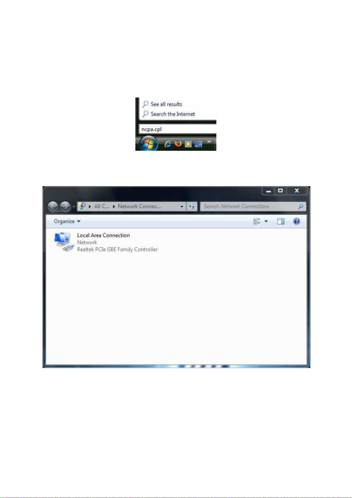
4.1 Configuring Microsoft Windows
Use
the
following procedure
1. In the Start
2.
When
the
Network Connecti
and click Properties.
to
configure a
menu search box,
7
computer running Microsoft Windows
type:
ons List
ncpa.cpl
appears, right-click
the Local
7.
Area Connection icon
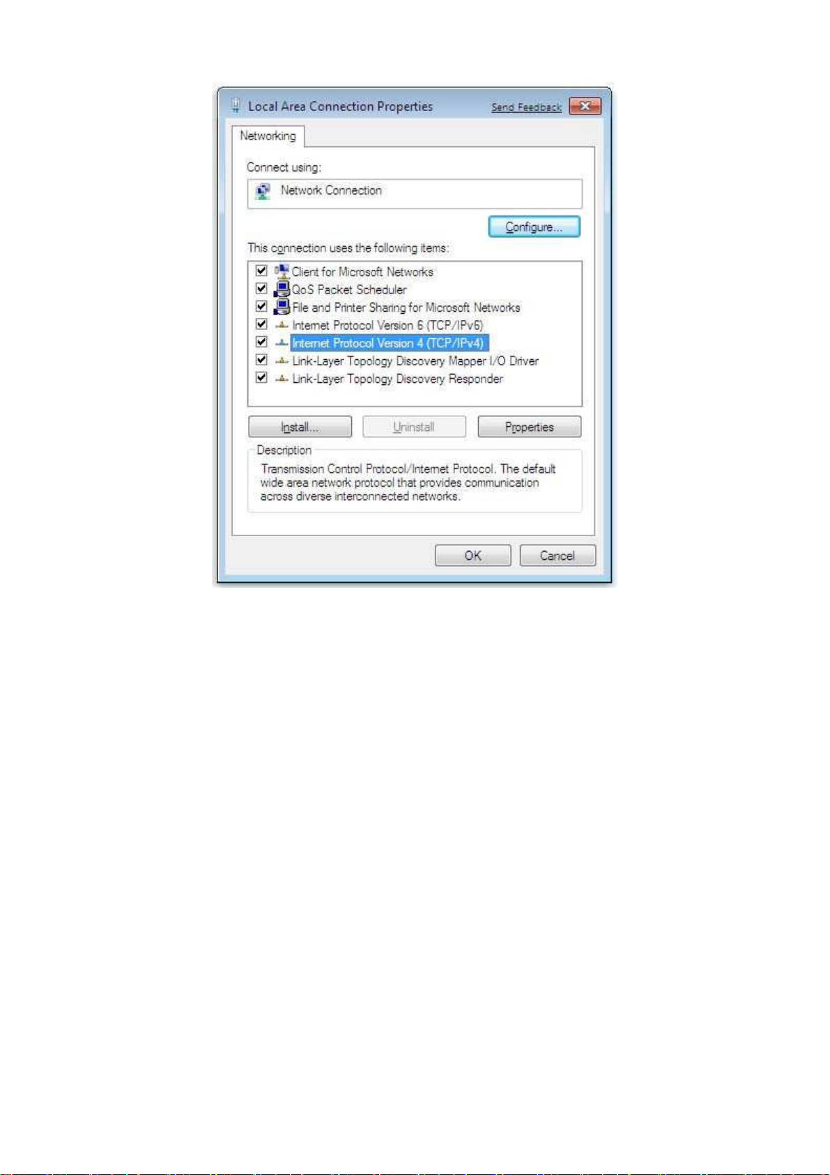
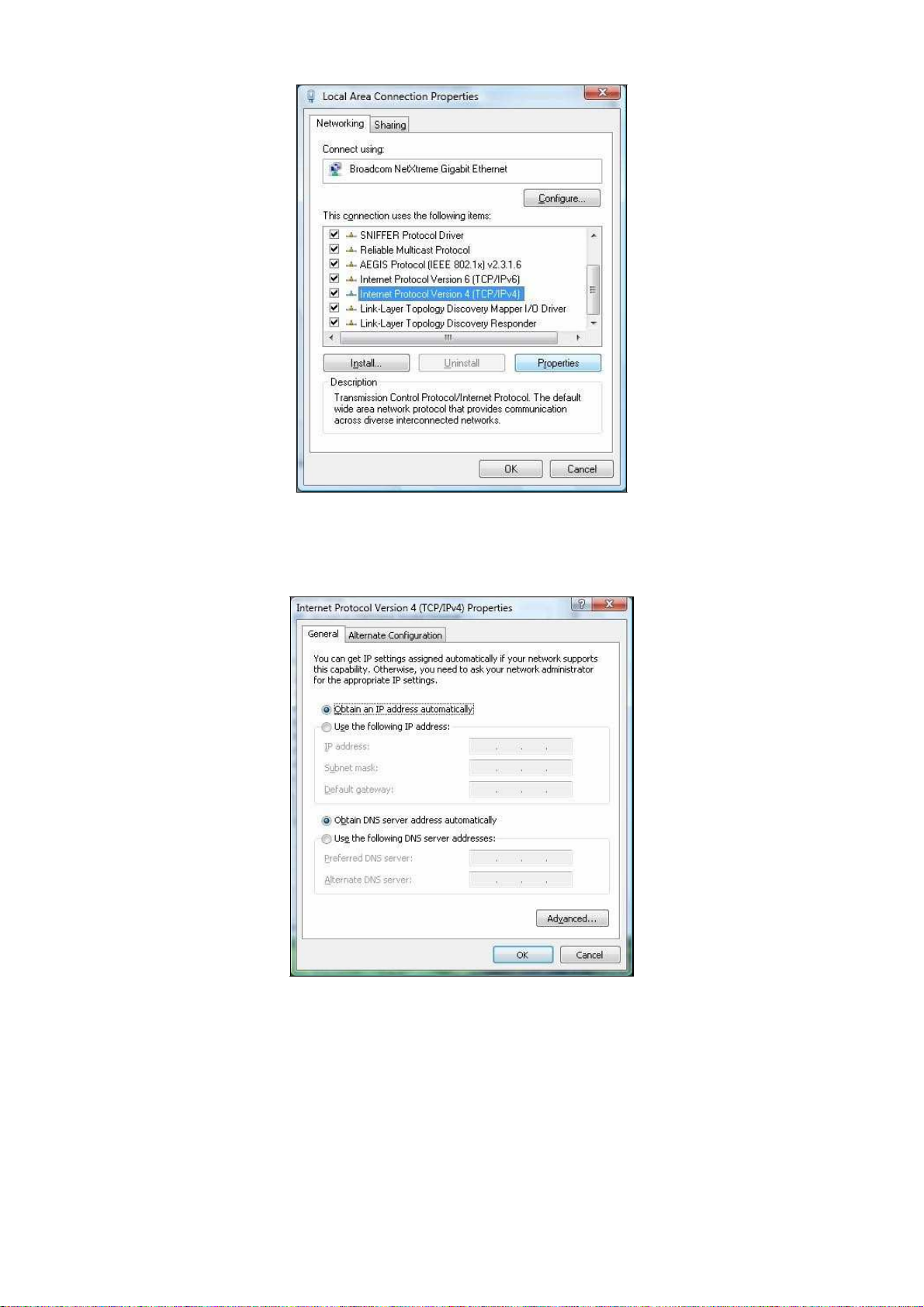
3. In the Net
Protocol
working tab,
click
either Internet Protocol Version 4 (TCP/IPv4)
Version 6 (TCP/IPv6), and then
click Properties.
or Internet
4. In the properties dialog box, click Obtain an IP address automatically
computer
for DHCP.
to
configure
your
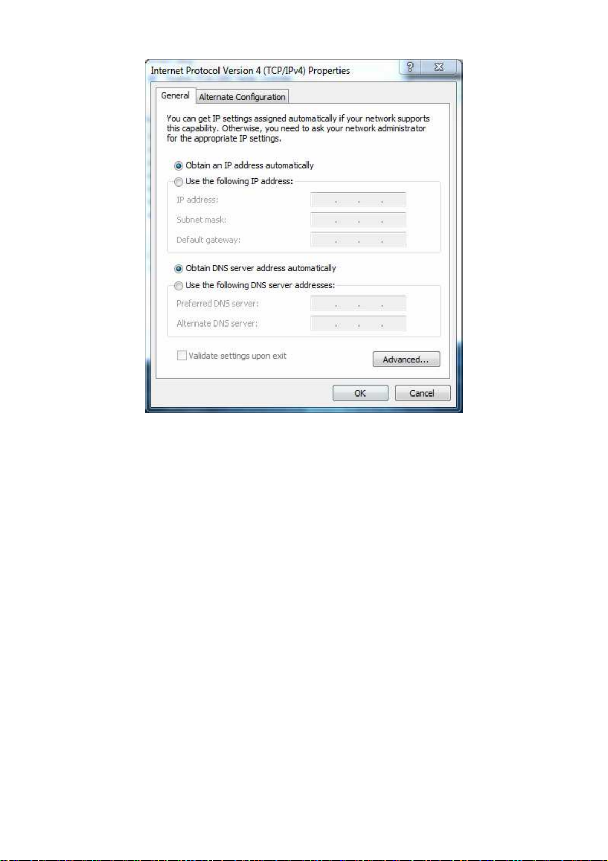
5.
Click
the
OK
button to
6.
Click
the
OK
button
save your changes and close
again
to
save your changes.
4.2 Configuring Microsoft Windows Vista
Use
the
following procedure
default interface. If
Windows
versions, perform
1.
On
the
and
Internet icon.
2.
Click View Networks Status
Connections.
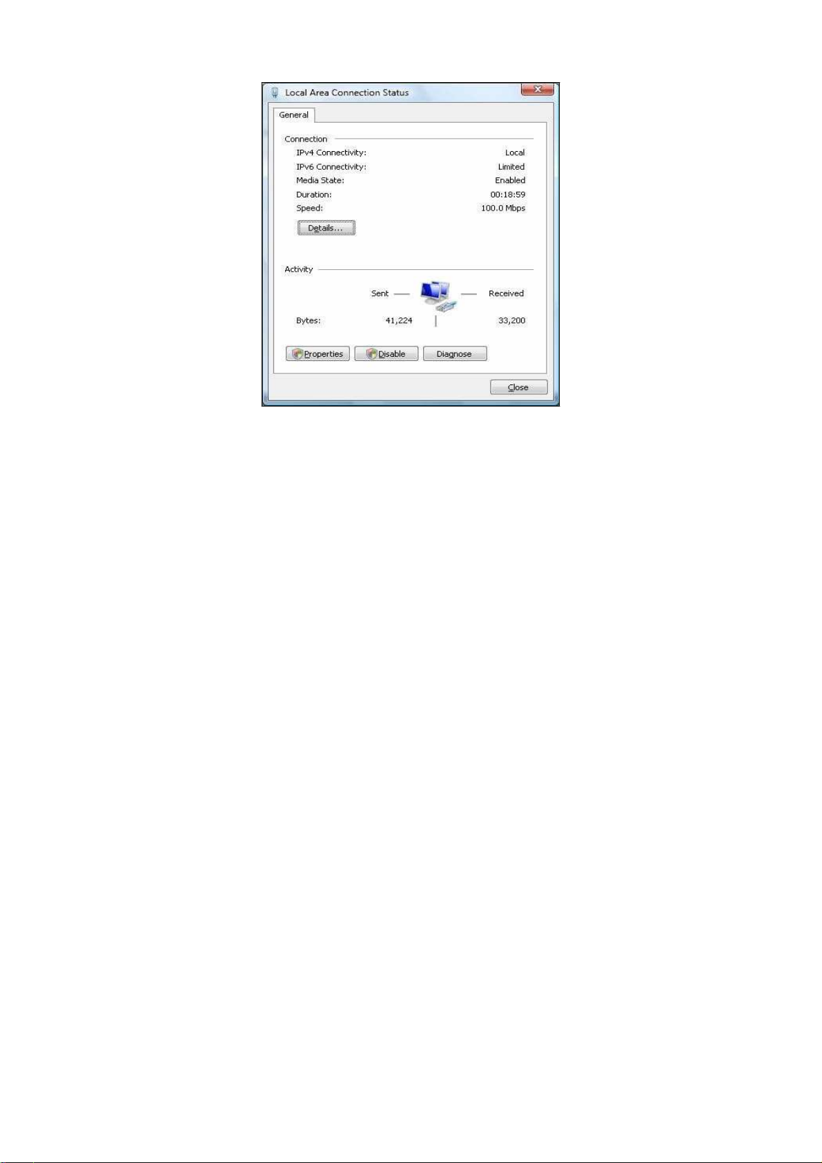
3. Right-click the Local
4.
Click Continue. The Local Area Connection Properties
5. In the
you use
Windows taskbar, click Start, click Control Panel, and then select
Local Area
to
configure a
the Classic interface,
the
procedure
and tasks
Area Connection
Connection Properties
computer running Microsoft Windows Vista
in section
the
dialog
where
the
icons and menus resemble
4.4.
and then
click Management Networks
icon and click Properties.
dialog box appears.
dialog box, verify
that Internet Protocol
box.
with the
previous
the Network
(TCP/IPv4) is checked. Then select
button.
The
Internet Protocol Version 4 Properties dialog box appears.
Internet Protocol (TCP/IPv4) and click
the Properties
6. In the
Internet Protocol
Version 4 Properties dialog box, click Obtain an IP address
automatically
7.
Click
8.
Click
the
the
to
OK
button to
OK
button
configure your computer
save your changes and close
again
to
save your changes.
for DHCP.
the
dialog
box.
4.3 Configuring Microsoft Windows XP
Use
the
following procedure
to
configure a
computer running Microsoft Windows XP
with the default
interface.
If
you use
versions, perform
1.
On
Internet Connections.
2.
Click
3.
Click Local
Area
4. In the
Area
the Classic interface,
the
procedure
the
Windows taskbar, click Start, click Control Panel, and then
the
Network
in section
Connecti
Area Connection for the Ethernet
Connection Status dialog box appears.
Local Area
Connection Status
Connection Properties
where
the
icons and menus resemble previous Window
4.4.
ons
icon.
adapter connected to the
dialog box, click
dialog box appears.
the Properties
click
Network and
OM2P V2. The Local
button.
The Local
s

5. In the
is checked. Then select
Local Area
Connection Properties
Internet Protocol (TCP/IP) and click
Internet Protocol (TCP/IP) Properties
6. In the
automatically
change and close
7.
Click
8. Restart
Internet Protocol (TCP/IP) Pr
to
configure your computer
the
Internet Protocol (TCP/IP) Pr
the
OK
button
your
computer.
again
to
4.4 Configuring Microsoft Windows
Use
the
2000
following procedure
installed.
1.
On
the
Windows taskbar, click Start,
2. In the
Control Panel window, double-click
to
configure your
dialog box, verify
dialog box appears.
operties
dialog box, click Obtain an IP address
for
DHCP.
save your changes.
2000
computer
point to Settings, and then
if
the Network
that Internet Protocol (TCP/IP)
the Properties
Click
the
operties
dialog
your computer
and Dial-up Connections icon.
button. The
OK
button to
save thi
box.
has
Microsoft Windows
click Control Panel.
s
If
the Ethernet adapter
in
your computer
is installed correctly,
the
Local Area
Connection
icon appears.
3.
Double-click
the Local
Area Connection
icon
for the Ethernet adapter connected to the
OM2P V2. The Local Area Connection Status dialog box appears.

4. In the
Area
5. In the
is checked. Then select
6.
Click Obtain an IP address automatically
7.
Click
dialog
8.
Click OK
9. Restart
Local Area
Connection Status
Connection Properties
Local Area
Connection Properties
Internet Protocol (TCP/IP) and click
the
OK
button to
save this
box.
button
your
again
to
computer.
save these
dialog box appears.
dialog box, click
dialog box, verify
to
configure
change and close
new changes.
the Properties
that Internet Protocol (T
the Properties
your computer
the
Local Area
button.
Connection Pr
The Local
button.
for DHCP.
CP/IP)
opertie
s
4.5 Configuring an Apple
Macintosh Computer
The following procedure describes how
10.2.
If
your Apple Macintosh is running Mac
to
configure TCP/IP on an Apple Macintosh running Mac OS
OS 7.x
or
later,
the steps you perform and
the scree
ns
you see may
as a guide
1.
2.
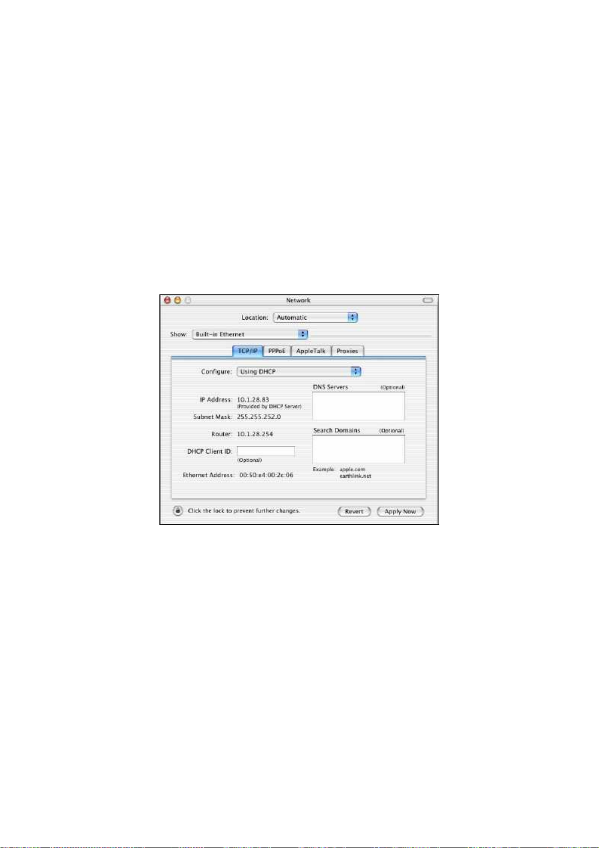
3. In the Configure field on
4.
differ slightly from the
to
configuring your Apple Macintosh
Pull down
Verify
the
that the
Apple Menu, click System Preferences,
NIC c
following. However, you should st
onnected to the
the
Click
Apply Now
to
apply your settings and close
ill be able
for TCP/IP.
and select
OM2P V2 is selected
in the Sho
TCP/IP tab, select Using DHCP.
the TCP/IP
Network.
dialog
to
use this procedure
w field.
box.
Chapter 5 Intr
odu
cing the
Web
Configurator
The OM2P V2 has a
built-in
Web
Configurator that lets you manage
the unit from
any location using
a
Web browser that supports
5.1 Logging
After
configuring
use
that computer’s
in
to the
the
Web Configurator
computer
Web browser to
1. Launch your Web browser.
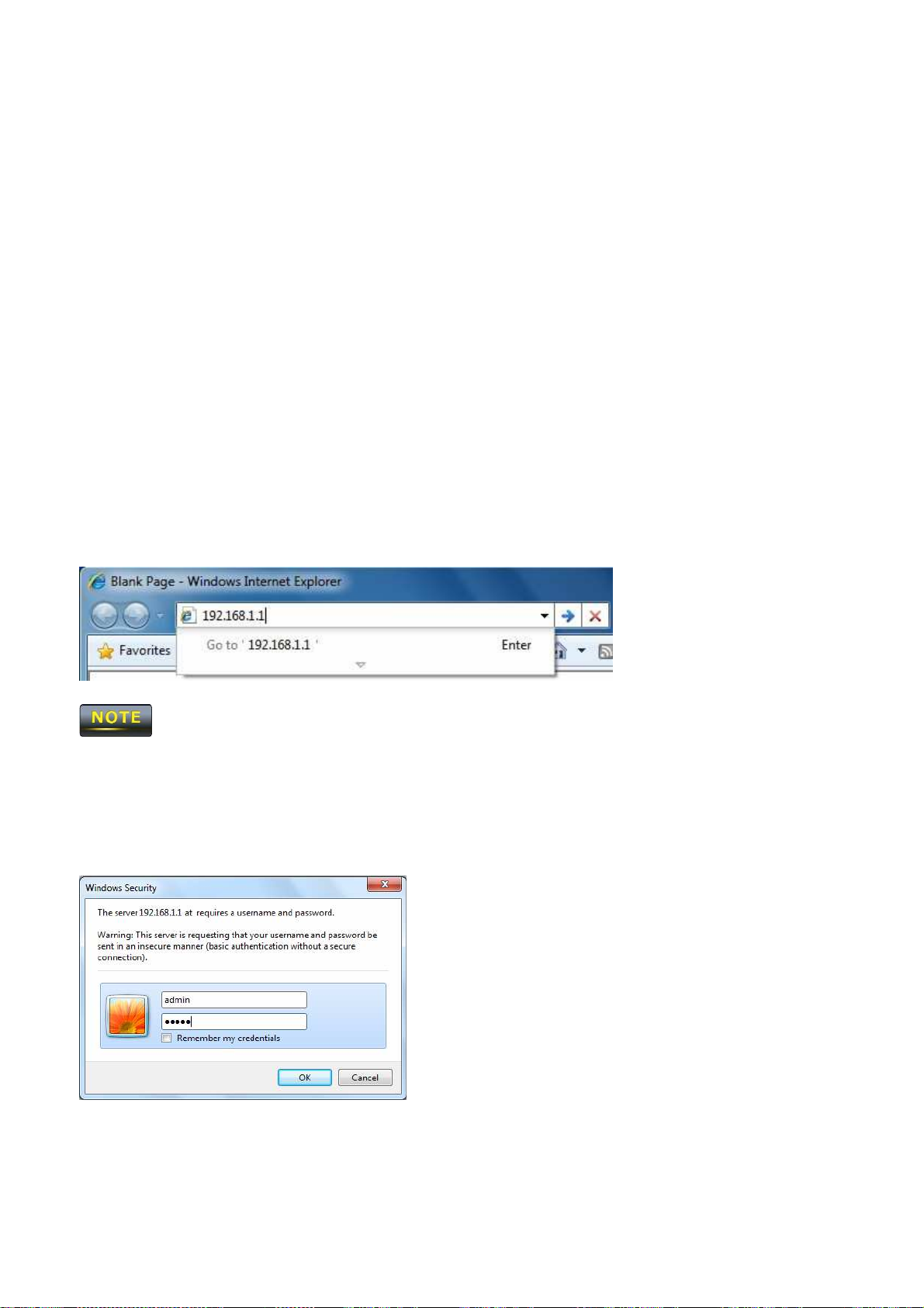
2. In
the browser
address
If
3. When
you changed
the Windows Security
HTTP and has JavaScript
for TCP/IP
bar, type
the
192.168.1.1 and press
OM2P V2 LAN IP address,
log
in to the
using
window appears,
installed.
the
procedure
OM2P V2 Web
the Enter key.
enter
type admin
appropriate
for
your operating system,
Configurator.
the correct IP address.
as
the
username
in the top
field
and
type admin
as
the
4. Click OK
You are now ready
password
to
use
the instructions in the
in the bottom field.
following chapters to
configure
the
OM2P V2.

5.2 Best Practices
Perform the
V2
more
effectively.
-
Change
following procedures regularly
the default
password. Use a password
to
make
the
OM2P V2 more secure and manage
that
is
not
easy
to
guess and
that contain
the
s
OM2P
different characters, such as numbers and letters.
F
or
more information,
-
Back
up the configuration
configuration
password, you
can be useful
will
see page
have
to reset the
69.
and be sure you know how
if the
OM2P V2 becomes unstable
OM2P V2
to its factory default settings and lose any
customized override settings you configured. However,
will not
configuration. For
have to completely reconfigure
more
information,
see page
the
OM2P V2. You can simply restore
The OM2P V2 username ca
to restore
if
you back up an earlier configuration, you
it. Restoring
or
crashes.
73.
nnot
be changed.
an earlier
If
you forget your
your last
working
Chapter 6 Status
The Status section
-
Main
-
Wireless Client List
on
the
navigation drop-down menu contains
- System Log
-
Connection Status
The following sections describe these options.
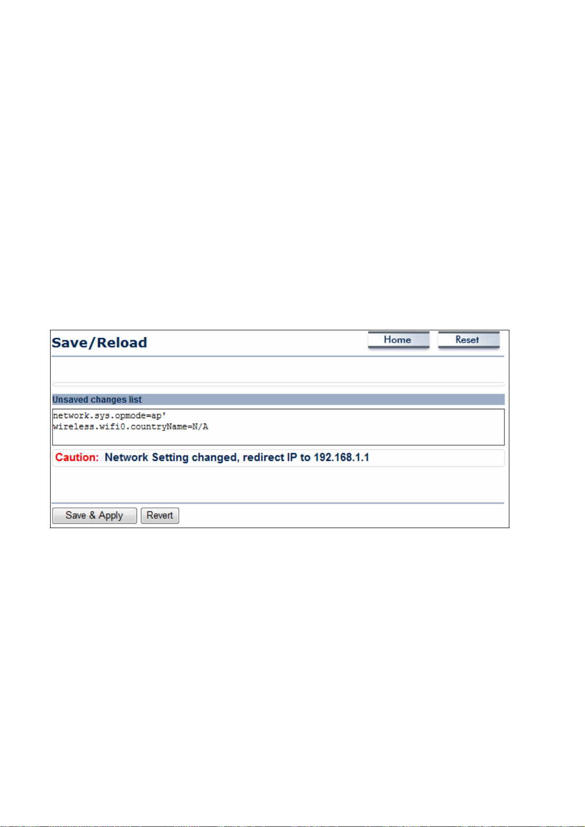
6.1 Save/Load
This
page lets you
the
unsaved changes
save
and apply the settings shown under Unsaved changes list,
and revert to the previous settings that were in effect.
the
following
options:
or cancel
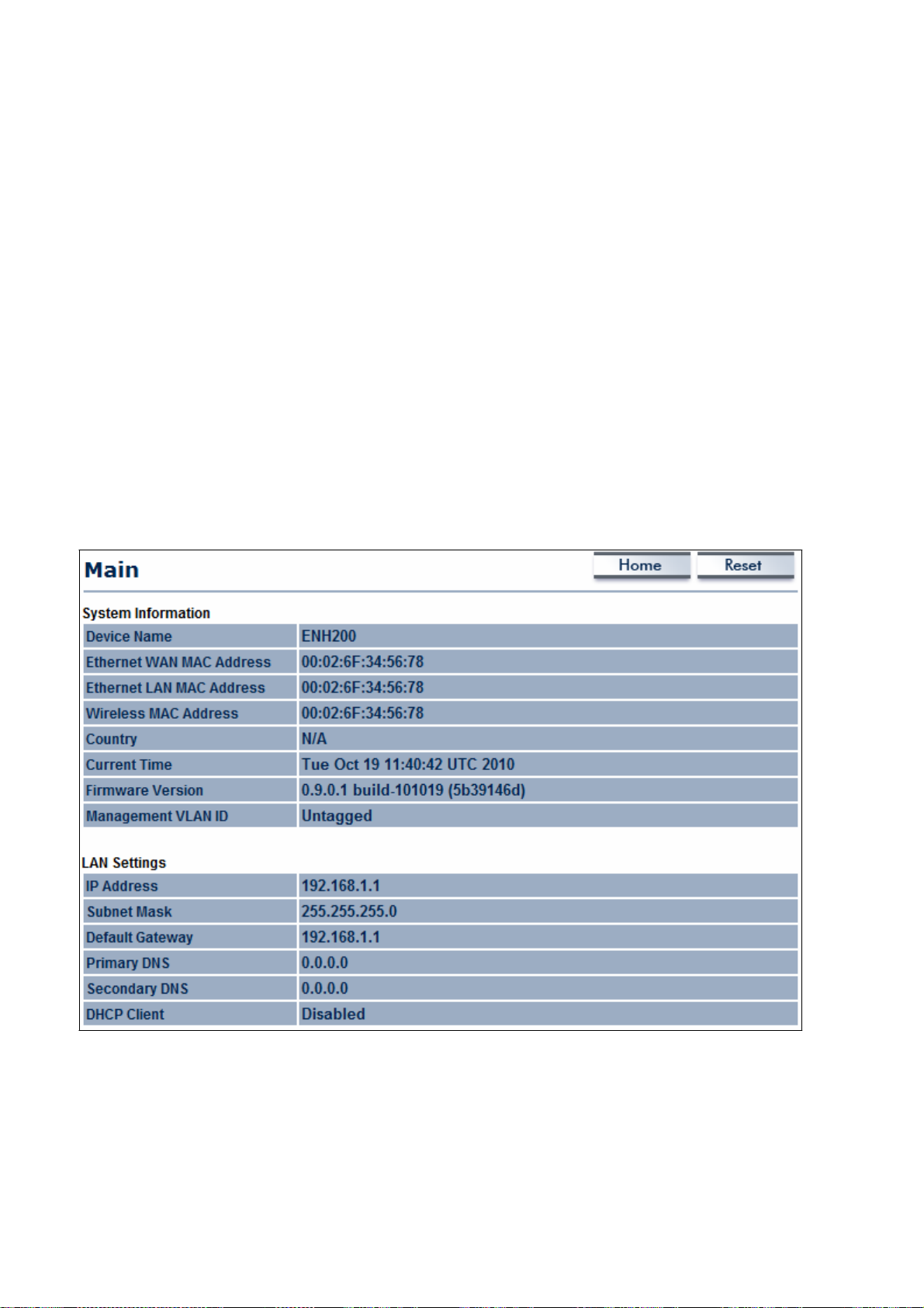
6.2 Main
Clicking the
Main
link under the Status
drop-down menu or clicking Home at the top-r
ight
of the Web Configurator
-
The System Information
m
ode, system
version.
-
The
LAN Settings section
subnet
-
The Current
channel. Since
as its
mask,
ESSID
up time, firmware
and MAC address.
Wireless Settings section
the
and security setti
shows
section
shows Local
OM2P V2
status information about the current operating mode.
shows
version, serial
supports
general system
information such
number, kernel version, and applicati
Area Network setting such
shows wireless
multiple-SSIDs,
information such
information about
as
the LAN
as
operati
IP address
as
frequency and
each SSID,
ngs, are displayed.
ng
on
,
such
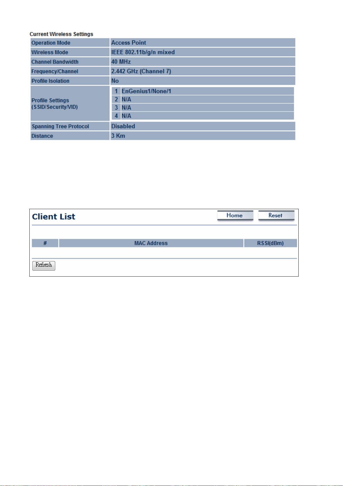
6.3
Wireless Client List
Clicking the Wireless Client List
clients associated
to the
OM2P V2, along with the MAC
each client. Clicking the Refresh
link under the Status
button updates
(refreshes)
drop-down menu
addresses
and signal strength for
the client list.
displays
the list
of

6.4 System
Log
u
The
OM2P V2 automatically
logs (records) events of possìble ìnterest ìn ìts ìnternal
memory.
down
To
menu.
vìew
the logged ìnformatìonclick
I睡
the System Log
lìnk
under the
Status
there ìs not enough ìnternal memory to log all events older events are deleted from the
System Log
Oct
ct
Oct
/
of f
Oct
unlocki ct 19 10:16:33 (none)user.warn kernel: ar5416SetSwitch
3witch co
Oct
Oct
Oct
Oct
Oct
Oct
ct 19 10:16:31 (none)user.info
Oct
Oct
Oct
dis
Oct
Oct
( I
JY1
19 10:16:58 (none)user.warn
19 10:16:58 (none)user.info
19 10:16:58 (none)user.info
Oct
19 10:16:34 (none)user.warn
19 10:16:34 (none)user.warn
19 10:16:33 (none)daemon.info dnsmðsq[823]: using
19 10:16:33 (none)daemon.info dnsmðsq[823]: using
19 10:16:33 (none)daemon.info dnsmasq[823): starte
19 10:16:33 (none)daemon.info dnsmasq[823): readinq
19 10:16:33 (none)daemon.info dnsmasq[823):
19 10:16:33 (none)daemon.info dnsmasq[823):
19 10:16:31 (none)user.info
19 10:16:31 (none)user.info
Oct
19 10:16:31 (none)user.info
for ct 19 10:16:30 (none)user.warn
connecti
19 10:16:30 (none)user.info
ct 19 10:16:25 (none)user.warn kernel:
19 10:16:25 (none)user.warn kernel:
19 10:16:25 (none)user.warn kernel: osif
AII
kernel: jffs2 build filesy
kernel: mïni fo:
kernel: mïni fo: using
kernel: jffs2 3can eraseblock(): End
kernel: jffs2 build filesy
kernel: device
m
kernel: br-lan: topology change detecte
kernel: br-lan:
kernel: br-lan:
Oct
19 10:16:30 (none)user.info
kernel: br-lan:
111
sing 3torage
read
compi1e time
athO
port
kernel: osif
kernel: device
port
start running
set SIOC80211NWID8 characters
vap
Home
-
entered
3(athO) entering lea
port
vap
3(athO) entering
init
stem(): era3in
directory
base
/etc/hosts - 1
'r1
directory:
stem():
Comant
local addresses onl
local addresses onl
dv
e
/
/resolv.conf
options:
promïscuou3
3(athO) entering
init
promïscuou3 mode
akeup from
: wait for
athO left
Resel
:
i 2.52 cac'---'
addre
'r1
ait
1
Rerresh
11
Clear l
drop-
log.
g
r-
I
惱v
d

6.5 Conneetion
StatU$
Clicking
the Connection
Status
link under the
Stat
drop-down menu
displays
the current
status of the networ
status
Wirel
Netwo
SSID
BSSID
Connection
wireless
ess
Type
S
mode current channel
s
Wiress Mode
Current Channe
S
urity
Tx
Da Ra
Mbps)
Current
se
ve
l
l
n
S
nal
strength
WAN
k。
The information shown includes
I l司lient
securit
Router
ydata ratenoise level and signal
IIEnGenius
I
network
type
SSIDBSSIDconnection
strength.
I
Refl
:es
h
I

6.6 DHCP
Client
Table
Clicking
the DHCP Client List link under the
Status drop-down
menu displays the clients
that
are associated
each
client are also shown.
to
the OM2P V2 through
DHCP
I
Refl
Client list
MAC
:es
h
I
addr
Clicking
11
DHCP.The MAC
the Refresh button
IP
addresses
updates
11
and signal strength for
(refreshes) the client lis
Home Resel
Ex
pires
t。

Chapter 7 System
This chapter describes how
to
change
the
7.1 Changing Operating Modes
The OM2P V2
-
Access Point
-
Client Bridge
-
WDS
-
Client Router
To select an operating mode, click System
supports four operating modes:
Bridge
OM2P V2 operating modes.
Properties under System Section. Then
go to System
.
> Operation mode.
Device Name: Enter
management.
This
name is not the
Operation Mode: Use
mode with
WDS, select
a name for the device.
SSID
The
name you type
appears
and is not broadcast to other devices.
the radio button to select an operating mode. To
Access Point
here and then enable the
WDS
in SNM
P
use Access Poi
nt
function in the Wireless
Network section
Click Accept
(see
section 8.6).
to confirm the cha
nges.

Clicking
Accept does not apply the changes.
section 4.1)
To
apply themuse
Status > Save/Load (see

Chapter 8
This
chapter
chapter carefully.
the network
mode
8.1
This
8.1.1
The OM2P V2
(see
Wireless Settings
section
Access Point
Wireless Configuration
describes
If you configure a setting improperly,
adversely.
Chapter 7).
describes basic wireless setti
the
OM2P V2’s wireless setti
Before you conti
Mode
supports
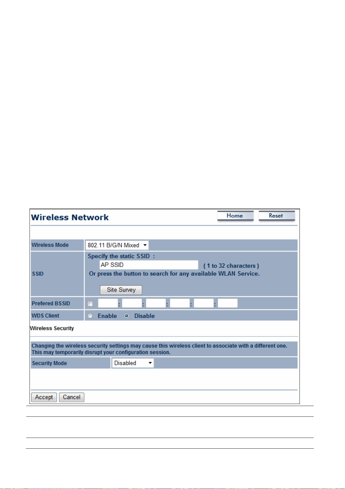
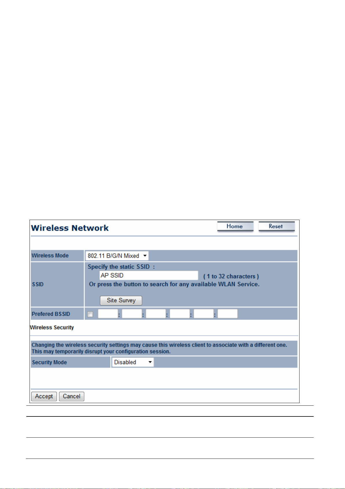
Access Point Mode. In this mode,
within range can connect to the
an example of an
The secti
ons
OM2P V2
operating in
that follow the figure below describe how to configure your
Access
OM2P V2
ngs.
Please
read the information in thi
it can impact performance and affect
nue, be sure you selected the appropriate operati
ngs.
For
to
more information,
users
access
the
WLAN. The
see
Chapter 12.
with a
wireless
following figure
client device
shows
Access Point Mode.
OM2P V2
for
s
ng
Point M
ode.
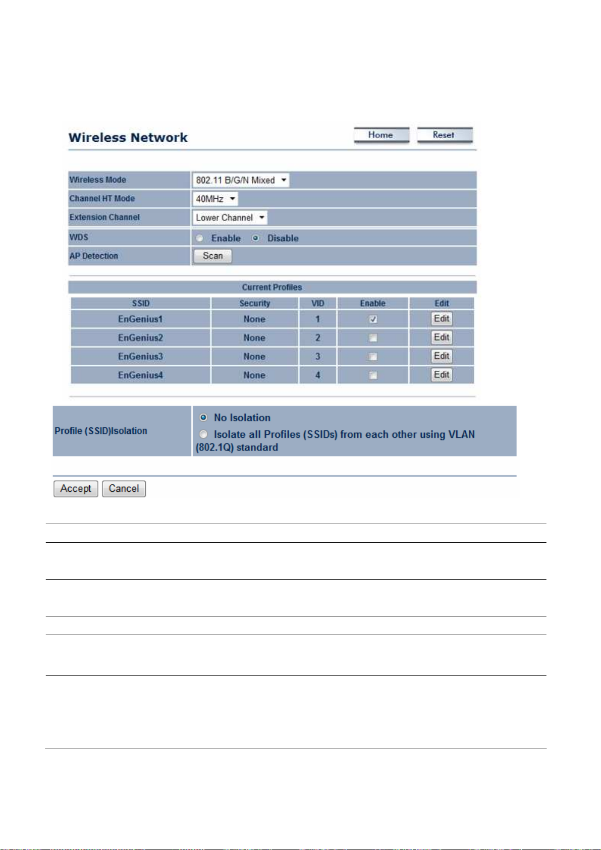
Wireless Mode
Channel HT Mode
Extension Channel
Auto
AP Detection
Current
Profile
Configure up to four different
Wireless
The
mode supports
802.11
b/g/
n mixed modes.
default channel bandwidth is 40 MHz.
The
larger the cha
nnel,
the better the transmission quality and speed.
Select upper or lower cha
channel function.
Check
AP
nearby
this option to enable auto-channel selection.
Detection can select the best channel to
areas
for
Access Points.
nnel. Your
selection may affect the
SSIDs.
accessing
groups.
the network,
Click Edit
you can arrange the
to configure the profile and check whether yo
use
by scanning
If many client
devices
devices
into SSI
Aut
o
will be
D
u
want to enable extra SSID.

Profile Isolation
A
ccept / Cancel
Clicking Accept
section 4.1).
Restricted Client to communicate with different VID by Selecting
the radio
Click Accept
return previous setti
does not apply the
button.
to confirm the
changes.
To apply them, use Status
ngs.
changes
or Cancel to
> Save/Load (see
cancel
and

SSID
Specify
the
SSID
for the current
profile.
VLAN ID
Suppressed
SSID
Station Separation
Wireless Security
Save / Cancel
Specify
Check
SSID
Click
communication between client devices.
See
Click Save
previous setti
the
VLAN
this option to hide the
will not appear in the site survey.
tag for the current
SSID
from clients.
profile.
the appropriate radio button to allow or preve
the
Wireless Security
to accept the
section.
changes
or Cancel to
ngs.
If checked, the
nt
cancel
and retur
n
8.1.2 Client
Bridge
Mode
Client Bridge Mode lets you connect two LAN
on the
reach all machines.
computers
The
Point/Wireless R
same physical network.
As a result, DHCP
as
though the clients resided on one
following figure
shows
outer, such
Since
the computers are on the
information generated by the
an example of an
as
the EnGenius E
The secti
ons
that follow the figure below describe how to configure your
Bridge Mode.
Wireless Mode
Wireless
mode supports
segments
via a
wireless
link
as
though they are
same subnet, broadcasts w
physical network.
OM2P V2
communicating with an Access
server
will reach all client
OA7530, operating in Client Bridge Mode.
802.11
b/g/
n mixed modes.
OM2P V2
for Client
ill
SSID
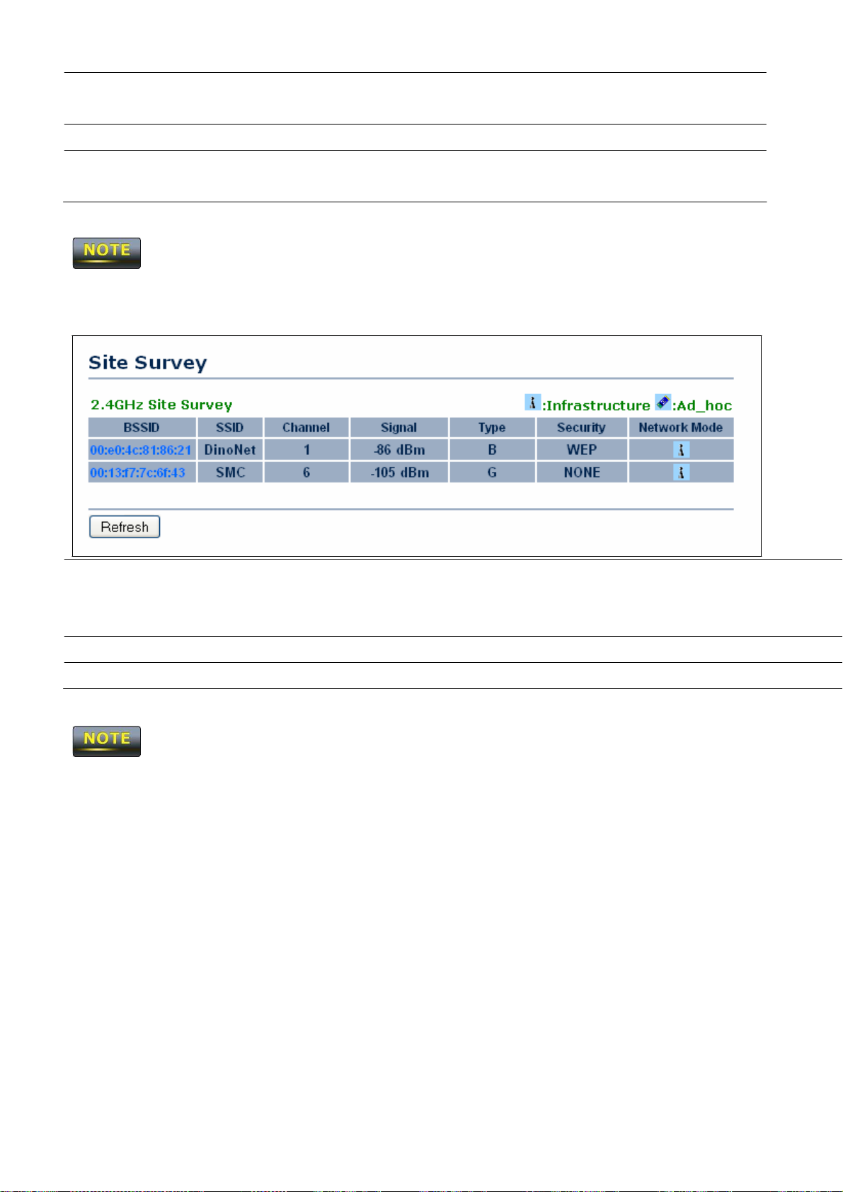
Site Survey
Specify
you select an
Scans
the
SSID
if known.
Access Point in the Site
nearby locations for
This
field is completed automatically if
Survey.
Access Points.
You
can select a

Prefer BSSID
WDS Client
Wireless Security
A
ccept / Cancel
Clicking Accept
section 4.1).
Profile
If you used the Site
discovered
Enter the MAC
the Site
Click
the appropriate radio button to enable or disable WD
Client.
See
section
Click Accept
return previous setti
does not apply the
Access Point to establish a connection.
address
Survey,
this field is completed automatically.
8.2
for information.
to confirm the
if known. If you select an
changes
or Cancel to
ngs.
changes.
To apply them, use Status
Survey,
the Web Configurator
Access Point in
S
cancel
and
> Save/Load (see
shows
nearby
Wireless Security
Refresh
If the
Access Point
has
been configured to
and must be completed ma
Access Points. To connect to an
Point’s
See
Click Refresh to
BSSID.
the
Wireless Security
scan
again.
suppress
section.
its
SSID,
nually.
Access Point,
the
SSID
click the Access
section will be bla
nk

8.1.3 WDS Bridge
Mode
Unlike traditional bridging.
linking
areas,
The
communicating with
t
he
that
several wireless access
where pulling wires is cost prohibitive,
following figure
shows
each other.
figure
connect to other
behaves as
a standard bridge that forwards traffic between the
OM2P V2 WDS bri
The secti
WDS
Wireless Mode
ons
that follow the figure below describe how to configure your
Bridge Mode.
WDS
Bridge Mode allows you to create large
points with
an example of three
In this configuration, the
Wireless
mode supports
WDS links. WDS
restricted or
dges).
OM2P V2
802.11
wireless
networks by
is normally used in large, open
physically im
configured for
OM2P V2
b/g/
n mixed modes.
possible.
WDS
Bridge Mode
device on the left side of
WDS
links (links
OM2P V2
for
Channel HT Mode
Extension Channel
A
ccept / Cancel
Clicking Accept
does not apply the
The
default channel bandwidth is 40 MHz.
The
larger the cha
nnel,
the better the transmission quality and speed.
Select upper or lower cha
channel function.
Click Accept
return previous setti
changes.
to confirm the
ngs.
To apply them, use Status
nnel. Your
changes
selection may affect the
or Cancel to
cancel
and
> Save/Load (see
Aut
o

section 4.1).
MAC Address
Enter the MAC
address
of the
Access Point to which you want to
Mode
A
ccept / Cancel
extend
Select Disable or Enable
Click Accept
wireless connectivity.
to confirm the
return previous setti
1.
Clicking Accept
does not apply the
changes.
section 4.1).
2. The Access Point to which you want to extend
V2’s
MAC
t
he
Access Point.
address
Not all
into its configuration.
Access Point supports this feature.
For
more information, refer to the documentation for
to disable or enable WDS.
changes
or Cancel to
ngs.
To apply them, use Status
wireless
connectivity must enter the
cancel
and
> Save/Load (see
OM2P
8.1.4 Client Router
In Client
Router Mode, the
t
he
that
Router Mode, you can
OM2P V2
can be configured to turn off the
only stations that have the
Mode
OM2P V2
LAN
64/128/152-bit
as
well
as TKIP/AES
secure tr
ansmission.
WEP
encryption security, WPA/WPA2, and WPA-
encryption security. It also supports
The
following figure
(WISP) Access Point in Client
how to
configure your
Wireless Mode
shows
OM2P V2
access
can
access
SSID
can be connected.
an
example
Router Mode.
for Client
Wireless
mode supports
the Internet
wirelessly
with the support of a
the Internet via a cable or
wireless
network name
The OM2P V2
VPN
pass-through for sensitive data
of an
OM2P V2
The sections
communicating with a
that follow the figure below
Router Mode.
802.11
b/g/
DSL modem.
(SSID)
also provides
WISP.
In this mode,
broadcast,
In AP
so
wireless
PSK/WPA2-PSK authentication,
Wireless ISP
describe
n mixed modes.
SSID
Site Survey
Specify
you select an
Scans
discovered
the
SSID
if known.
Access Point in the Site
nearby locations for
This
field is completed automatically if
Survey.
Access Points.
Access Point to establish a connection.
You
can select a
Prefer BSSID
Wireless Security
A
ccept / Cancel
Clicking Accept
section 4.1).
Profile
If you used the Site
Enter the MAC
the Site
See
section 10.2.
Click Accept
return previous setti
does not apply the
address
Survey,
this field is completed automatically.
to confirm the
changes.
if known. If you select an
changes
or Cancel to
ngs.
To apply them, use Status
Survey,
the Web Configurator
Access Point in
cancel
and
> Save/Load (see
shows
nearby
Wireless Security
Refresh
If the
completed ma
Access Point
nually.
Access Points. To connect to an
Point’s
See
the
Click Refresh to
has
been configured to
BSSID.
Wireless Security
scan
suppress
section.
again.
its
Access Point,
SSID,
the
click the Access
SSID
section must be

8.2
Wireless Security Settings
The Wireless Security Settings
section lets you configure the EOH200’s
security modes: WEP
,
WPA-PSK, WPA2recommend you
8.2.1 WEP
Security
Mode
PSK, WPA-
use WPA2-
PSK
PSK.
Select
Mixed,
WEP
WPA, WPA2,
and
WPA Mixed.
We st
rongl
y
from the drop-down list to begin the configuration.
Auth Type
Input
Type
Key Length
Default
Key
default.
Key1
Key2
Key3
Key4
Select Open System
or Shared.
Select an input type of Hex or ASCII.
Level
of
WEP
encryption applied to all
Select a 64/
Specify
128/152-bit
which of the four
Specify a password
typed character is
Specify a password
typed character is
Specify a password
typed
character
is
Specify a password
typed character is
WEP keys. Choices
password le
WEP keys
ngths.
the
OM2P V2 uses as
for security key index No.1.
masked
by a dot
(
l
).
for security key index No.2.
masked
by a dot
(
l
).
for security key index No.3.
masked
by a dot
(
l
).
for security key index No.4.
masked
by a dot
(
l
).
are
its
For security, each
For security, each
For security, each
For security, each

802.11
will drop from
n does not allow WEP/WPA-
802.11
8.2.2 WPA-PSK
Security
Mode
n to
802.11g.
Select
PSK/WPA-PSK TKIP
WPA-PSK
from the drop-down list to begin the
security mode.
The
connection mode
Encryption
Passphrase
Group Key Update
Interval
802.11
will drops from
n does not allow WEP/WPA-
802.11
c
onfiguration.
Select Both,
• Both =
•
•
Specify
is
masked
Specify
n to
802.11g.
TKIP,
uses TKIP
TKIP
= automatic encryption with WPA-
pass
phrase.
AES
= automatic encryption with WPA2-
pass
phrase.
the security
by a dot
how often, in
PSK/WPA-PSK TKIP
or
AES as
and AES.
the encryption type.
password. For security,
(
l
).
seconds,
the group key cha
security mode.
PSK; requires
PSK; requires
each
typed character
nges.
The
connection mode
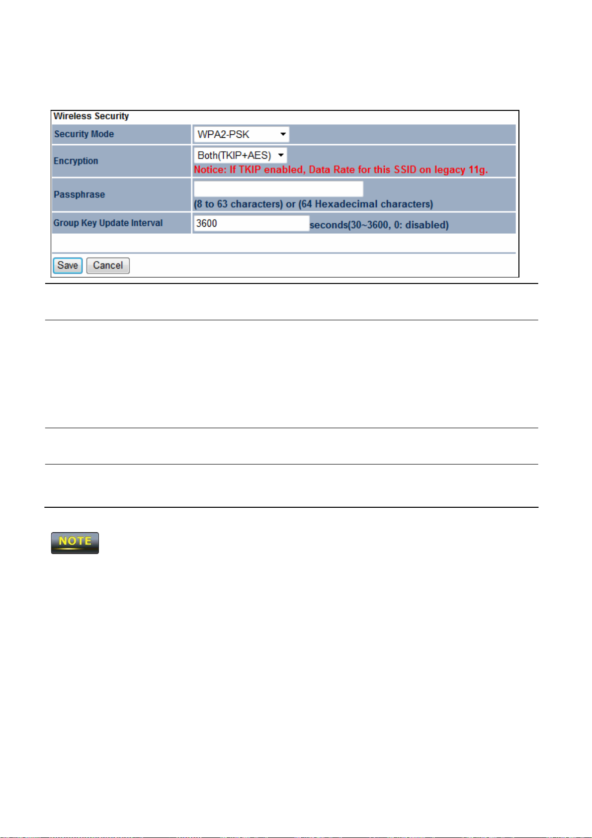
8.2.3
WPA2-PSK
Security
Mode
Select WPA2-PSK from the drop-down list to begin the
c
onfiguration.
Encryption
Passphrase
Group Key Update
Interval
802.11
n does not allow WEP/WPA-
will change from
802.11
Select Both,
• Both =
•
•
Specify
is
masked
Specify
n to
802.11g.
TKIP,
TKIP
= automatic encryption with WPA-
pass
phrase.
AES
= automatic encryption with WPA2-
pass
phrase.
the security
by a dot
how often, in
PSK/WPA-PSK TKIP
or
uses TKIP
password. For security,
(
AES as
the encryption type.
and AES.
l
).
seconds,
security mode.
the group key cha
PSK; requires
PSK; requires
each
typed character
nges.
The
connection mode

8.2.4
WPA-PSK Mixed
Security
Mode
Encryption
Passphrase
Group Key Update
Interval
WPA-PSK
Mixed can allow multiple security modes at the
Select
c
WPA-PSK
onfiguration.
Select Both,
• Both =
•
TKIP
= automatic encryption with WPA-
pass
phrase.
•
AES
= automatic encryption with WPA2-
pass
phrase.
Specify
is
Specify
the security
masked
how often, in
by a dot
Mixed
TKIP,
or
uses TKIP
(
from the drop-down list to begin the
AES as
and AES.
the encryption type.
PSK; requires
PSK; requires
password. For security,
l
).
seconds,
the group key cha
each
typed character
nges.
same time.
802.11
n does not allow WEP/WPA-
will change from
802.11
n to
PSK/WPA-PSK TKIP
802.11g.
security mode.
The
connection mode
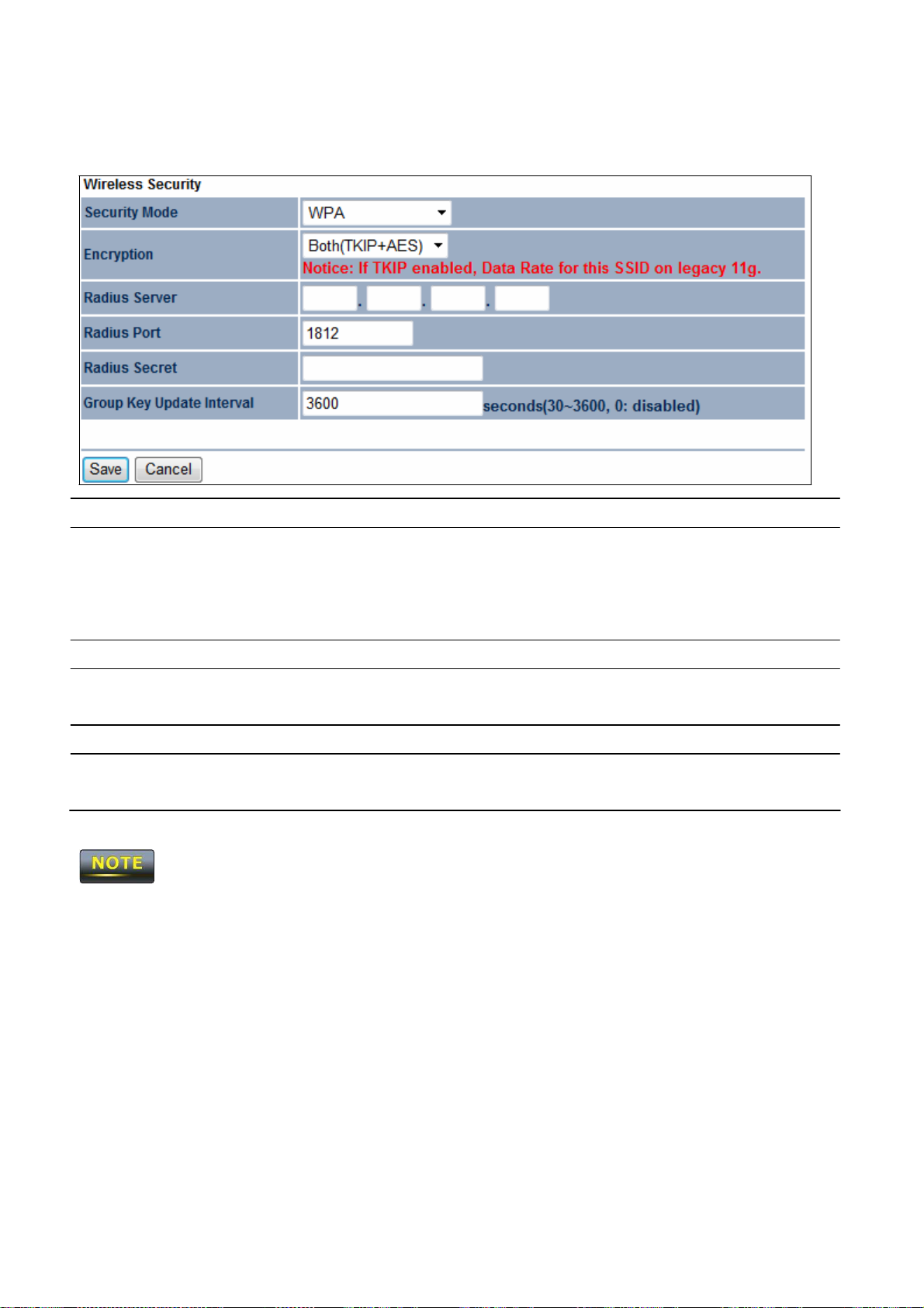
8.2.5
WPA
Security
Mode
Select WPA from the drop-down list to begin the configuration.
Encryption
Radius Server
Radius Port
Radius Secret
Group Key Updat
Interval
802.11
n does not allow WEP/WPA-
will drops from
e
802.11
Select Both,
• Both =
•
TKIP
•
AES
Specify
Specify
TKIP,
or
uses TKIP
AES as
and AES.
the encryption type.
= automatic encryption with WPA-
= automatic encryption with WPA2-
the
IP address
of the
RADIUS server.
the port number that your
authentication. Default port is
Specify RADIUS secret furnished by the
n to
Specify
802.11g.
how often, in
seconds,
PSK/WPA-PSK TKIP
security mode.
PSK.
PSK.
RADIUS server uses for
1812.
RADIUS server.
the group key cha
The
connection mode
nges.
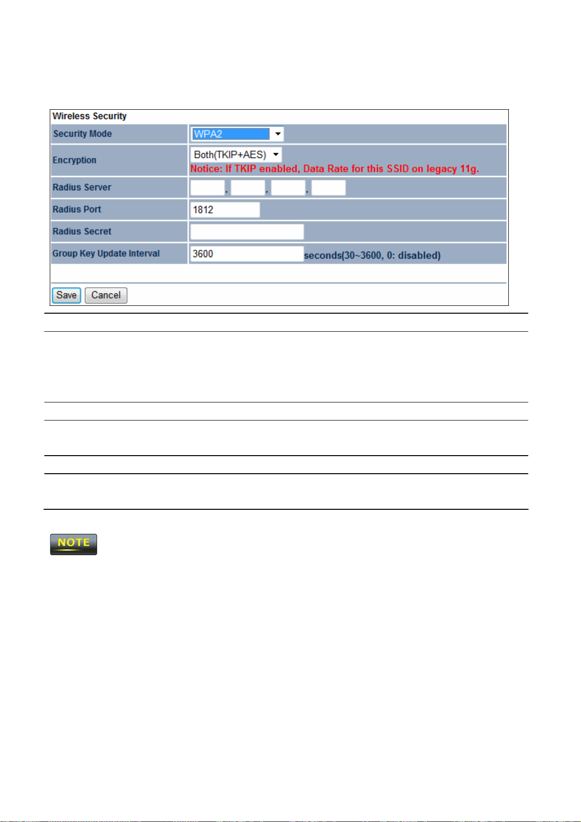
8.2.6
WPA2
Security
Mode
Select WPA2 from the drop-down list to begin the configuration.
Encryption
Radius Server
Radius Port
Radius Secret
Group Key Updat
Interval
802.11
from
n does not allow WEP/WPA-
802.11
n to
e
802.11g.
Select Both,
• Both =
•
TKIP
•
AES
Specify
Specify
authentication. Default port is
TKIP,
or
uses TKIP
AES as
and AES.
the encryption type.
= automatic encryption with WPA-
= automatic encryption with WPA2-
the
IP address
the port number that your
of the
RADIUS server.
RADIUS server uses for
1812.
Specify RADIUS secret furnished by the
Specify
how often, in
seconds,
PSK/WPA-PSK TKIP
the group key cha
security mode.
PSK.
PSK.
RADIUS server.
nges.
The
date rate will
drop

8.2.7
WPA Mixed
Security
Mode
Select WPA
c
onfiguration.
Mixed
from the drop-down list to begin the
Encryption
Radius Server
Radius Port
Radius Secret
Group Key Updat
Interval
802.11
n does not allow WEP/WPA-
will change from
e
802.11
Select Both,
• Both =
•
TKIP
•
AES
Specify
Specify
authentication. Default port is
TKIP,
or
uses TKIP
AES as
and AES.
the encryption type.
= automatic encryption with WPA-
= automatic encryption with WPA2-
the
IP address
of the
RADIUS server.
the port number that your
1812.
Specify RADIUS secret furnished by the
Specify
n to
802.11g.
how often, in
seconds,
PSK/WPA-PSK TKIP
the group key cha
security mode.
PSK.
PSK.
RADIUS server uses for
RADIUS server.
nges.
The
connection mode

8.4 Wireless
Adva
nced
Settings
Data Rate
Select a data rate from the drop-down list. The
data rate affects
RTS/CTS
Distance
Threshold
Antenna Selection
Short GI
Aggregation
Merges data packets
thro
ugh
put. If you select a low data rate value, for
example, the
throughput is reduced but the transmission distance increases.
Specify
causes RTS/CTS packets
more ba
Specify
distances
Specify
Sets
before sampling data.
increase through
installations due to
reflecti
the threshold
package size
to be sent more often and consumes
ndwidth.
the distance between
Access Points
may drop high-speed connections.
the internal antenna type.
the time that the
receiver
waits for
Using a short
put, but can also
ons. Select
increased
the option that works best for your installation.
sensitivity to radio-frequency
into one packet. This
for RTC/CTS. A small number
RF
(400ns)
increase
and clients.
reflections to settle
guard interval can
error rate in some
option
Longer
reduces the
out

Wireless Traffic
Shaping
Incoming Traffic Limit
Outgoing Traffic Limit
A
ccept / Cancel
1.
Changing
Wireless
accept all default setti
2.
Clicking Accept
does not apply the
section 4.1).
number of packets, but
Check
this option to enable
increases
shaping regulates the flow of packets
deliver improved Quality of Service.
Specify
Specify
Click Accept
return previous setti
Advanced Settings may
ngs,
unless
the
the
wireless
wireless
transmission speed used for
transmission speed used for
to confirm the
ngs.
adversely
you are familiar with the
changes.
To apply them, use Status
packet sizes.
wireless traff
leaving an interface to
changes
affect
or Cancel to
wireless performance. Pleas
wireless options.
ic shaping. Traffic
downloading.
uploading.
cancel
and
> Save/Load (see
e

8.5 Wireless
MAC F
ilter
Wireless
MAC Filters
are used to allow or deny network
access
to
wireless
clients according to
their MAC
access
ACL
Mode Determines whether network
addresses. You
OM2P V2.
MAC Address Filter
can manually add a MAC
The
default setting is
clients whose MAC
on this page. Choices
Allow
Enter the MAC
MAC
address
Disable Wireless
addresses
are Disable, Deny MAC
in the list.
address
of the device.
to restrict the permission to
MAC Filters.
access
is granted or denied to
appear in the MAC Address table
in the list, or
0.
Add
Apply
Click
Add to add the MAC
Click
Apply
to apply the cha
address
nges.
to the MAC Address table.

8.6 WDS
Link Settings
Using
WDS
Link Settings,
you can create a
wireless
backbone link between multiple access
points that are part of the
expanded using multiple
is traditionally required.
MAC Address
same wireless network. This
Access Points
Enter the
without the need for a wired backbone to link them,
Access Point’s
allows a
MAC
address
wireless
network to be
to which you want to
as
Mode
A
ccept / Cancel
extend the
Select Disable or Enable
Click Accept
wireless area.
to confirm the
return previous setti
Clicking Accept
section 4.1).
does not apply the
changes.
The Access Point to which you want to extend
MAC
address
Access Point.
into its configuration.
Not all
Access Point supports this feature.
For
more information, refer to the documentation for the
from the drop-down list.
changes
or Cancel to
ngs.
To apply them, use Status
wireless
connectivity must enter the
cancel
and
> Save/Load (see
OM2P V2’s

Chapter 9
LAN
Setup
This
chapter
describes
9.1 IP Settings
This
section is only
the
available
OM2P V2 Local
for
Non-Router Mode.
Area Network
IP
(LAN) setti
ngs.
settings lets you configure the
OM2P
V2 LAN port
IP Netw
ork Setting
IP address.
Select whether the
OM2P V2 IP address
will
use
the static
IP
IP Address
V2. IP Suet
Default Gateway
gateway.
Secondary DNS
DNS.
A
ccept / Cancel
Mask
Primary
DNS Enter the
If you change the LAN
Apply.
address specif
automatically
DHCP server .
Enter the
Enter the
Enter the
IP address
OM2P V2
OM2P V2
OM2P V2
Enter the
OM2P V2 secondary
Click Accept
return previous setti
IP address,
you will be directed to the new
ied in the IP Address field or be obtained
when the
OM2P V2
connects to a device that
of the
subnet mask
OM2P
.
default
primary DN
to confirm the
S.
changes
or Cancel to
cancel
ngs.
IP address
after you click
has
and
a

9.2 Spann
ing Tree
Settings
Spanning
Tree Status
Enable or disable the
OM2P V2
Spanning
Tree function.
Bridge Hello Time
Bridge
Bridge
Priority
A
ccept / Cancel
Max Age
Forward
Specify
often the
i
nformati
Local
Area Network
Specify
spanning tree does not send a hello packet for a long period of
time,
it is
Delay Specify
is the time spent in
before the Forwa
that when a new bridge comes onto a busy network,
some traffic before participating.
Specify
Click Accept
return previous setti
Bridge Hello
OM2P V2 sends
on
about the topology throughout the entire Bridged
Bridge Max Age,
assumed
Bridge Forward
Time,
in
seconds. This
hello packets
in
seconds.
If another bridge in the
to be dead.
Delay,
each
in
seconds. Forwa
of the Listening and Learning states
rding state is entered.
value determine how
to communicate
rding delay time
This
delay is provided so
the Priority number.
to confirm the
Smaller
changes
number
has
or Cancel to
greater priority.
cancel
ngs.
it looks at
and
Clicking Accept
section 4.1).
does not apply the
changes.
To apply them, use Status
> Save/Load (see

Chapter 10 Router Settings
This
section is only
available
for AP Router Mode and Client Router Mode.
10.1 WAN Settings
This
chapter
c
onnections:
- Static IP
- DHCP
-
PPPoE
describes
the
OM2P V2
WAN settings.
There
are four types of WAN
-
PPTP
Please
contact your
10.1.1 Static IP
Select Static
address,
IP for your WAN connection if your
subnet
ISP
mask,
to find out which settings you should choose..
ISP
provided information about which IP
default gateway, primary
DNS,
and
secondary DNS
to
use.

Internet Connection
Type
Account Name
Domain
Name
MTU
IP Address
Subnet Mask
Gateway
Primary
Secondary DNS
Discard
IP Address
DNS
Ping on WAN
Select Static
Enter the account name provided by your ISP.
Enter the domain name provided by your ISP.
Specify
IP to begin configuration of the Static IP connection.
the Maximum Transmit Unit
size.
It is recommended you
accept the default setting of Auto. Otherwise, packets
fragmented downstream if the MTU is set too high or too low
which impacts network performance. In extreme
setting that is too low can prevent the
OM2P V2
cases,
from
establishing some connections.
Enter the WAN port
Enter the WAN
Enter the WAN gateway
Enter the primary
Enter the
Check
secondary DNS IP a
to Enable to recognize pings on the
IP address.
IP
subnet mask
IP address
DNS IP address
IP
.
.
.
ddress.
OM2P V2
will be
,
an MTU
WAN
A
ccept / Cancel
Clicking Accept
section 4.1).
interface or Disable to block pings on the
interface. Note: Pi
by
hackers to
test whether the
extra security from hackers.
Click Accept
return previous setti
does not apply the
nging IP addresses
IP address
to confirm the
changes.
To apply them, use Status
ngs.
OM2P V2
WAN
is a common method used
is valid. Blocking pings provides some
changes
or Cancel to
cancel
and
> Save/Load (see

10.1.2 DHCP (Dynamic
Select
need to enter account name
Internet Connection
Type
DHCP as
your WAN connection type to obtain an
IP)
as
your hostname and, optionally,
Select
DHCP
to begin configuration of the
IP address automatically.
DNS information.
DHCP connection.
You will
Account Name
Domain
Name
MTU
Enter the account name provided by your ISP.
Enter the domain name provided by your ISP.
Specify
the Maximum Transmit Unit
size.
accept the default setting of Auto. Otherwise, packets
It is recommended you
will be
fragmented downstream if the MTU is set too high or too low
which impacts network performance. In extreme
setting that is too low can prevent the
OM2P V2
cases,
from
an MTU
establishing some connections.
,

Get Automatically
From ISP
Use These
Discard
A
ccept / Cancel
Clicking Accept
DNS Servers Click
Ping on WAN
does not apply the
Click
this radio button to obtain the
DNS
DHCP server.
the radio button to set up the
Primary DNS
DNS servers manually.
Check
to Enable to recognize pings on the
interface or Disable to block pings on the
interface. Note: Pi
by
hackers to
test whether the
nging IP addresses
IP address
is a common method used
is valid. Blocking pings provides some
extra security from hackers.
Click Accept
return previous setti
to confirm the
changes.
To apply them, use Status
ngs.
changes
or Cancel to
automatically from the
and Secondary
OM2P V2
OM2P V2
WAN
WAN
cancel
and
> Save/Load (see
section 4.1).
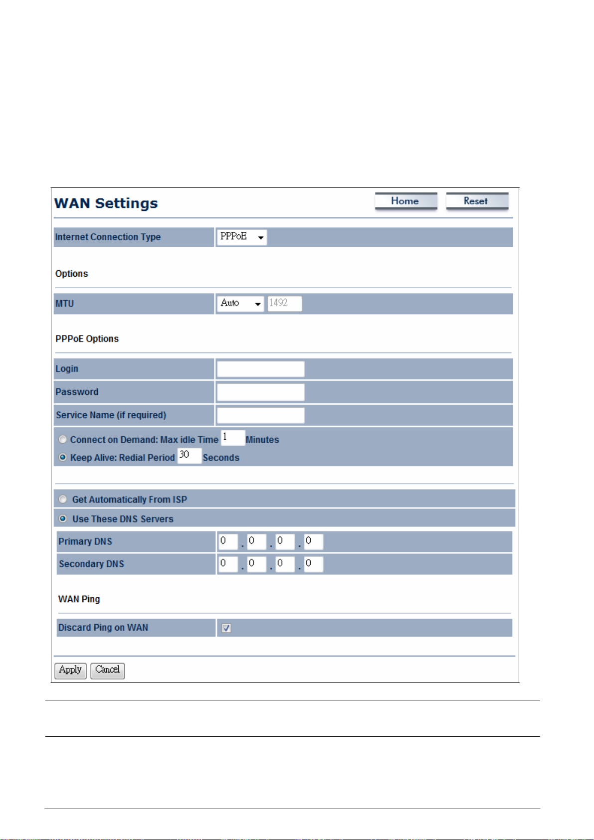
10.1.3
PPPoE (Point-to-P
oint Protocol
over Ethernet)
Select Point to Point Protocol over Ethernet (PPPoE)
Your ISP
DSL services. Remove
not work with your
will provide you with a
your
PPPoE
OM2P
username
and
password. This
software from your com
V2.
Internet Connection
Select
PPPoE
to begin configuration of the
Type
if
your
ISP uses a PPPoE connection.
selection is typically used for
puter,
as
it is not needed and will
PPPoE connection.
MTU
Specify
accept the default setting of Auto. Otherwise, packets
the Maximum Transmit Unit
size.
It is recommended you
will be
fragmented downstream if the MTU is set too high or too low
which impacts network performance. In extreme
cases,
an MTU
,

Login
Password
Service Name
C
onnect
Keep
on Demand
Alive
Get Automatically
From ISP
Use These
Discard
DNS Servers Click
Ping on WAN
setting that is too low can prevent the
OM2P V2
from
establishing some connections.
Enter the Username provided by your ISP.
Enter the Password provided by your ISP.
Enter the Service
Name provided by your ISP.
Select the radio button to specify the maximum idle time.
Internet connection will disconnect when it reach the maxim
idle time, but it will automatically connect when user tries to
access
Select whether to keep the Internet connection
the network.
always on, or
enter a redial period once the internet lose connection.
Select whether to obtain the
server.
the radio button to set up the
DNS
automatically from the DHCP
Primary DNS
and Secondary
DNS servers manually.
Check
to Enable to recognize pings on the
OM2P V2
WAN
um
A
ccept / Cancel
Clicking Accept
section 4.1).
interface or Disable to block pings on the
interface. Note: Pi
by
hackers to
test whether the
extra security from hackers.
Click Accept
return previous setti
does not apply the
nging IP addresses
IP address
to confirm the
changes.
To apply them, use Status
ngs.
OM2P V2
WAN
is a common method used
is valid. Blocking pings provides some
changes
or Cancel to
cancel
and
> Save/Load (see

10.1.4 PPTP
Select
(PPTP)
(optional)
PPTP
connection. You will
WAN
!il
Use
DNS
Settings
These
(Point-to-Point Tunneling Protocol)
as your
WAN
connection type
if
your ISP uses a Point-to-Point-Tunneling
need to provide the IP address subnet
(optional) server
IPusername
and password provided by your ISP.
DNSServe
Protocol
maskdefault gateway
Home
Resel
WAN Ping
I
Apply
PingonWAN
I
Internet Connection
Type
|o
!。I
o
!。I
o
!。I
Select PPTP to begin config uration of the
o
PPTP
connection.

MTU
IP Address
Subnet Mask
Gateway
IP Address
PPTP Server
Username
Password
C
onnect
Keep
on Demand If you want the
Alive
If you want the
Specify
accept the default setting of Auto. Otherwise, packets
fragmented downstream if the MTU is set too high or too low
which impacts network performance. In extreme
setting that is too low can prevent the
the Maximum Transmit Unit
size.
It is recommended you
cases,
OM2P V2
from
will be
,
an MTU
establishing some connections.
Enter the WAN port
Enter the WAN
Enter the WAN gateway
Enter the
Enter the
Enter the
IP address
username
password
IP address.
IP
subnet mask
.
IP address
of the
PPTP server.
provided by your ISP.
provided by your ISP.
OM2P V2
to end the Internet connection after it
IP
.
has been inactive for a period of time, select this option and enter
t
he
number of minutes you want that period of inactivity to last.
OM2P V2
to periodically check your Internet
Get Automatically
From ISP
Use These
Discard
A
ccept / Cancel
DNS Servers Click
Ping on WAN
c
onnection, select this option. Then specify how often you wa
the
OM2P V2
to check the Internet connection. If the
connection is
down, the
Obtains the
OM2P V2
DNS
automatically re-establishes your connectio
automatically from
the radio button to set up the
DHCP server.
Primary DNS
and Secondary
DNS servers manually.
Check
interface or Disable to block pings on the
interface. Note: Pi
by
test whether the
to Enable to recognize pings on the
nging IP addresses
hackers to
IP address
is valid. Blocking pings provides some
OM2P V2
OM2P V2
WAN
WAN
is a common method used
extra security from hackers.
Click Accept
return previous setti
to confirm the
ngs.
changes
or Cancel to
cancel
and
nt
n
Clicking Accept
section 4.1).
does not apply the
changes.
To apply them, use Status
> Save/Load (see

10.2
LAN Settings (Router Mode
)
IP Address Enter
the LAN port
IP address
.
IP Subnet
WINS Server
Use Router As DHCP
Mask Enter
IP Enter
Server
Starting IP Address
Ending
WINS Server
A
ccept / Cancel
IP Address
IP
Check
Specify
private
subnet
specif
IP Address.
Specify
private
subnet
specif
IP Address.
Enter the
Click Accept
the LAN
the
WINS Server IP.
IP
subnet mask
this option to enable the
the starting
IP addresses. The
as
the ending
IP address
starting
IP address;
ied here must be the
the ending
IP addresses. The
as
the starting
IP address
ending
IP address;
ied here must be the
IP address
of the
WINS server.
to confirm the
.
OM2P V2
internal
DHCP server.
range for the pool of allocated for
IP address
must be on the same
that is the first three octet
same as
the first three octets in End
range for the pool of allocated for
IP address
must be on the same
that is the first three octets
same as
changes
the first three octets in Star
or Cancel to
cancel
and
s
t
Clicking Accept
section
4.1).
does not apply the
return previous setti
changes.
To apply them, use Status
ngs.
> Save/Load (see

10.3
VPN
Pass Through
VPN Passt
hrough
allows a
secure
virtual private network
(VPN)
connection between tw
o
computers. Enabling the options on this page opens a
pass
through the
OM2P V2
without
interruption.
PPTP Pass
L2TP Pass
IPSec Pass
A
ccept / Cancel
Through
Through
Through
Check
Check
Check
this option to enable
this option to enable
this option to enable
Click Accept
to confirm the
VPN
port and
PPTP
pass-through mode
L2TP
pass-through mode
IPSec
pass-through mode.
changes
enables
or Cancel to
connections to
.
.
cancel
and
Clicking Accept
section 4.1).
return previous setti
does not apply the
changes.
ngs.
To apply them, use Status
> Save/Load (see
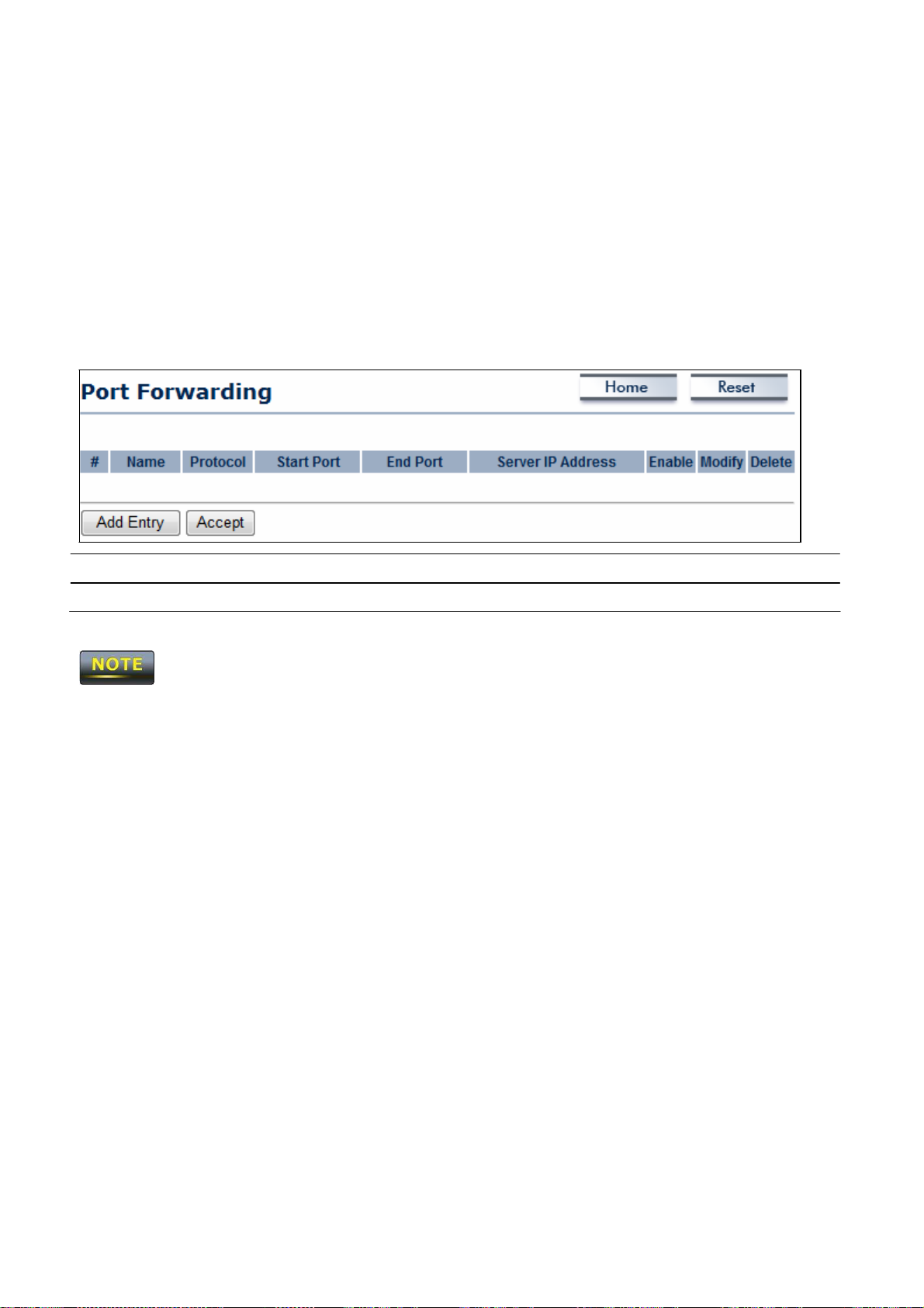
10.4
Port Forwarding
Port
forwarding can be used to open a port or range of ports to a device on your networ
k
Using port forwarding, you can set up public
Internet make certain re
computers equipped to handle the re
(HTTP)
forwarded to
Add Entry
A
to be forwarded to
ccept
192.168.1.2.
quests on your network,
quests. If,
IP address 192.168.1.2,
Click
Add Entry
Click Accept
to confirm the cha
services
for
on your network.
the
OM2P V2
example,
all
HTTP re
When
can forward those re
you set the port number 80
quests from outside
to add port forwarding rules.
nges.
users
users
from the
quests to
are
Clicking Accept
section 4.1).
does not apply the
changes.
To apply them, use Status
> Save/Load (see
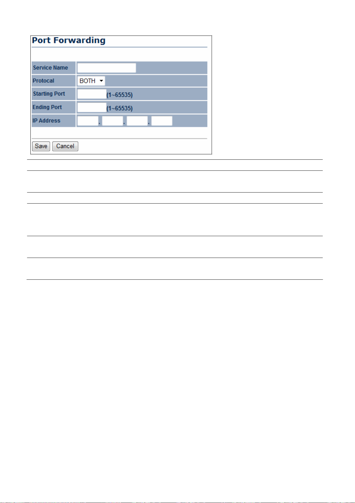
Service Name
Enter a name for the port forwarding rule.
Protocol
Select a protocol for the application: Choices
UDP.
Starting Port
Enter a starting port number.
Ending Port Enter
starting and ending ports will forward
specif
IP Address
Enter the
where
Save / Cancel
Click Save
settings.
are Both, TCP,
and
an ending port number. All ports numbers between the
users
to the
IP
address
ied in the IP Address field.
IP address
users
will be re
to apply the
of the
server
directed.
changes
computer on the LAN networ
or Cancel to return previous
k

10.5
DMZ
If you have a computer that cannot run Internet applications properly from behind the
OM2P
V2, you can allow the computer to have unrestricted Internet
that
computer
client to the DMZ may
a last resort.
DMZ Hosting
DMZ Address
A
ccept / Cancel
as
a Demilitarized Zone (DMZ) host with unrestricted Internet
expose
that computer to a variety of security
Enables
Enter an
Internet
or
IP address
access.
Click Accept
disables
the
OM2P V2
of the computer that will have
to confirm the
changes
access. Enter
risks,
so
DMZ function.
or Cancel to
the
IP address
access.
use
unlimited
cancel
of
Adding a
this option as
and
Clicking Accept
section 4.1).
return previous setti
does not apply the
changes.
ngs.
To apply them, use Status
> Save/Load (see
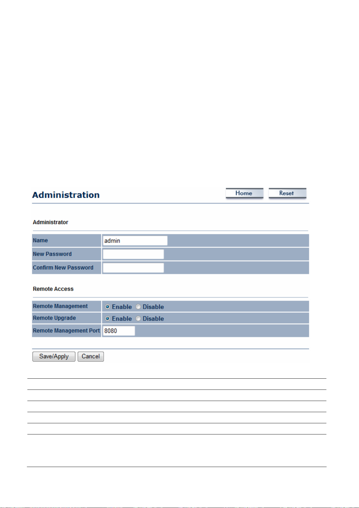
Chapter 11 Management Settings
The Management
section lets you configure administration, management
VLAN, SNMP
settings, backup/restore setti
chapter
11.1 Administration
Click
password
and the default
c
onfiguratio
describes
these setti
the Administration
used to log on to the
password
n settings from being
link under the Management
ngs, firmware upgrade, time setti
ngs, and log setti
ngs.
menu to change the user name and
OM2P V2
Web Configurator
. The
default user name is admin
is admin. Changing these settings protects the
accessed
by unauthorized
users.
ngs. This
OM2P V2
Name
Password
Confirm Password
Remote Management
Remote Upgrade
Remote Management
Port
Enter a new
Enter a new
Re-enter
Enable or disable remote management.
Specify
If remote management is enabled, enter the port number to be
used for remote management. For
port number
username
password
the new
whether the
for logging in to the Web Configurator.
for logging in to the Web Configurat
password
OM2P V2
8080, enter http://<IP
for confirmation.
firmware can be upgraded remotely.
example:
If you specify the
address>:8080 to access
or

the
OM2P V2
Web Configurator.
Save/Apply / Cancel
Clicking Save/Apply
Click Save/Apply to apply the
previous setti
changes
the settings immediately. You
ngs.
changes
or Cancel to retur
cannot undo the action.
n
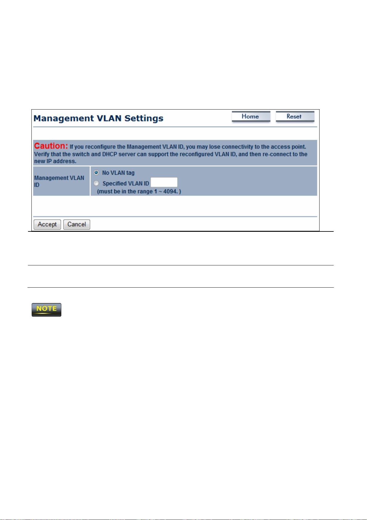
11.2
Mana
geme
nt VLAN
Click
the Management
VLAN link under the Management
menu to
assign a VLAN
tag to the
packets.
so that they
VLAN
A
VLAN
is a group of computers on a network whose software
behave as
do not have to be
if they were on a separate
physically
located next to one another on the LAN
Local
Area Network
has
(LAN).
been configured
Computers on
Management VLAN ID If your network includes VLANs and if tagged packets need to
pass through the Access Point,
enter the VLAN
ID. Otherwise
click No VLAN tag .
,
A
ccept / Cancel
Click Accept
return previous setti
1.
If you reconfigure the Management
V2. Verify that the
the
2.
Clicking Accept
OM2P V2
DHCP server
using the new
does not apply the
IP address.
section 4.1).
to confirm the
changes
ngs.
VLAN ID,
you may lose your connection to the
supports the reconfigured
changes.
To apply them, use Status
or Cancel to
VLAN
cancel
and
OM2P
ID and then reconnect to
> Save/Load (see

11.3
SNMP
Settings
Click
the SNMP Settings
link under the Management
menu to monitor network-attache
d
devices
using the Simple Network Management Protocol
(SNMP). SNMP
(called “protocol data unit’s) to be sent to various parts of a network.
messages,
Information Bases.
SNMP Enable/Disable
SNMP-compatible devices
Enable or disable the
(called agents) return data stored in their Management
OM2P V2 SNMP
allows messages
Upon receiving these
f
uncti
on. Contact
Location
C
ommunity
C
ommunity
Name
Name
Trap Destination IP
Address
Trap Destination
C
ommunity Name
Save/Apply / Cancel
Enter the contact details of the device
Enter the location of the device.
Enter the
read-only
Enter the
and write
Enter the
password
access.
password
access.
IP address
for
accessing
for
accessing
where
SNMP
Enter the
password
of the
SNMP
Click Save/Apply to apply the
previous setti
ngs.
Clicking Save/Apply change the setting immediately. You
.
the
the
SNMP
SNMP
community for
community for read
traps are to be sent.
trap community.
changes
or Cancel to retur
cannot undo the action.
n

11.4
Backup/Restore Settings
Click
V2’s
the Backup/Restore Setting
link under the Management
menu to
save
the
OM2P
current settings in a file on your local disk or load settings onto the device from a local
disk. This
feature is particularly convenient administrators who have
devices that need to be configured with the
This
page also lets you return the
this procedure,
Save
A Copy of Current
any
changes
Settings Restore Saved
Settings
from a File
Click
To restore settings that have been previously backed up,
OM2P V2
made to the
Backup to
several OM2P V2
same setti
ngs.
to its factory default settings. If you perform
OM2P V2
save
default settings will be lost.
the current configured setti
ngs.
click
Revert
to Factory
Default Settings
Browse, select the file,
Click
this button to restore the
default setti
ngs.
and click Restore.
OM2P V2
to its factory

11.5
Firmw
are Upgrade
Click
the Firmware Upgrade link under the Management
menu to upgrade the firmware
of
the device. To perform this procedure,
downloaded the appropriate firmware from your
vendor.
The firmware upgrade procedure can take few mi
the
firmware upgrade,
restarts automatically after the
as
it
can cause
the
device
upgrade completes.
nutes.
to
crash
Do
not
power
or
become unusable. The OM2P V2
off the
OM2P V2 during

11.6
Time
Settings
Click
the Time Settings link under the Management
menu to configure the
OM2P V2
system time. You can enter the time manually or,
OM2P V2 with
Network Time Protocol
Manually Set Date and
(NTP) server.
Manually specify the date and time.
Tim
e
Automatically Ge
t
Select a time zone from the drop-down list and check
to
ensure accuracy, synchronize
the
whethe
r
Date and Time
Save/Apply / Cancel
Clicking Save/Apply
you want to enter the
default
NTP server.
Click Save/Apply to apply the
previous setti
changes
the setting immediately. You
ngs.
IP address
changes
of an
NTP server
or
use the
or Cancel to retur
cannot undo the action.
n
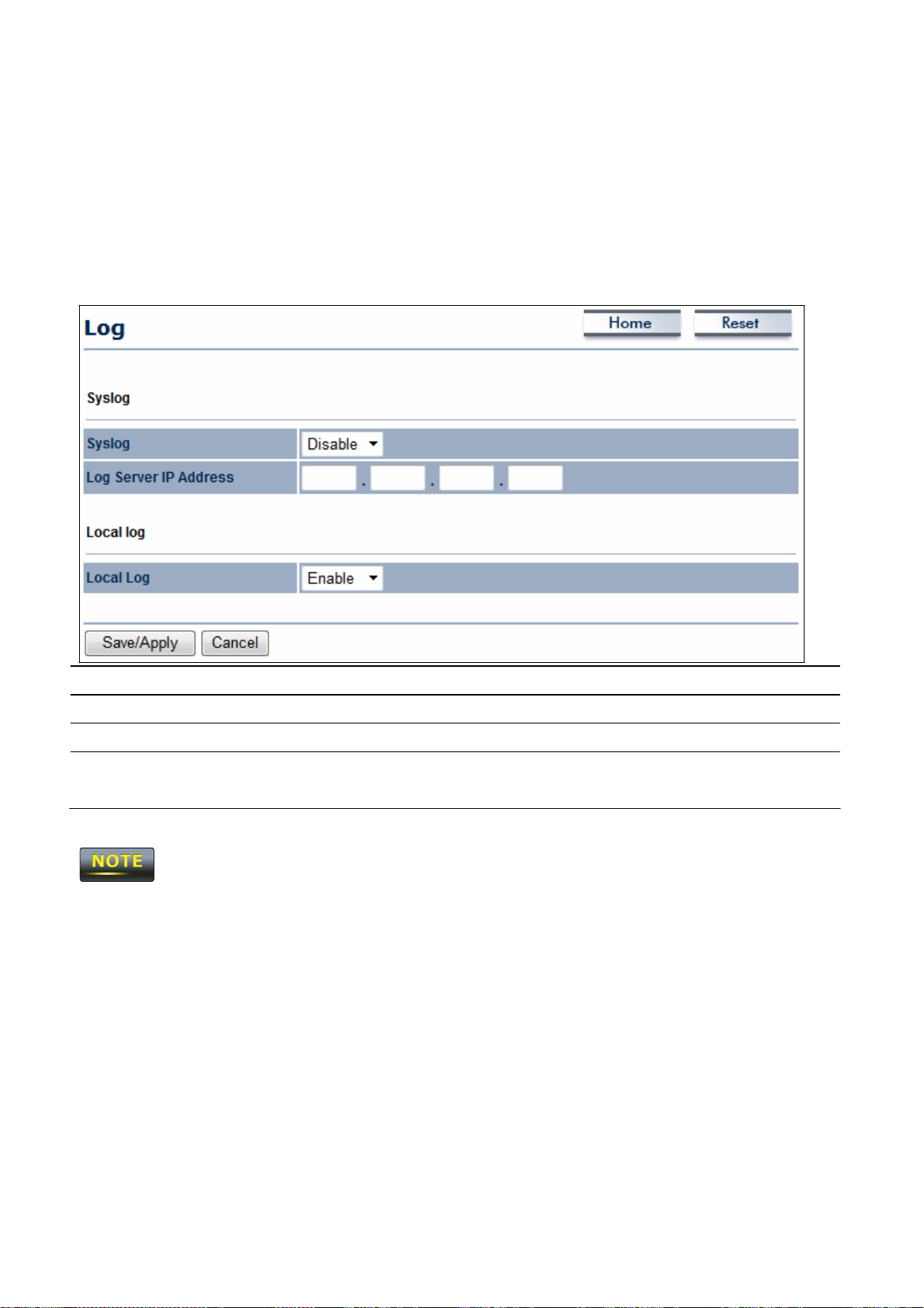
11.7
Log
Click
the Log link under the Management
menu to display a list of events that are triggere
d
on the
e
rror
OM2P V2 Ethernet
occurs
department
for debugging
Syslog
on the system
pur
poses.
and
wireless
interfaces.
or when a report
Enable or disable the
You can consult this log if an unknown
needs
to be sent to the technical support
OM2Psyslog function.
Log Server
IP Address Enter
Local Log
Save/Apply / Cancel
Clicking Save/Apply
the
IP address
of the log server.
Enable or disable the local log service.
Click Save/Apply to apply the
previous setti
changes
the settings immediately. You
ngs.
changes
or Cancel to retur
cannot undo the action.
n

11.8
Diagnostics
Click
the Diagnostics link under the Management
menu to ascertain connection quality and
trace the routing table to the target.
Target
IP
Enter the
IP address
you would like to search.
Ping Packet Size
Number
Start
of
Ping
Pings
Traceroute Target
Start Traceroute
Enter the packet
Enter the number of times you want to ping.
size
of
each ping.
Click Start Ping to begin pinging.
Enter an
IP address
Click Start Tr
or domain name you want to tr
aceroute
ace.
to begin the trace route operation.

Chapter 12 Network Conf
igu
ration Examples
This
chapter provides step-by-step descriptions for using the
The
Access Point Mode’s default configuration allows the
OM2P V2’s
OM2P V2
operating modes.
to act
as
a central unit of
a WLAN or
are
reserved
12.1
Access Point
Access Point
Ste
Ste
Ste
Ste
Ste
as
a root device of a wired envir
for future confi
guration.
onment. Repeater mode and Mesh network mode
p1 Log in to the Web Configurator with your browser by entering
the default
p2
p3
p4
Use
site
Select channel with
Specify
configure multiple
p5 Verify the
IP address
survey
the
SSID
VLAN
192.168.1.1
to
scan channels available
less
interferences.
for your broadcast
SSID
at the
SSID
same time.
in nearby areas
and you can also
identif ier to separate services
.
among clients
Ste
Ste
For
p6
p7
more
Set the authentication setti
Click
Apply
advanced setti
ngs
.
to
save
all cha
nges.
ngs, refer to the previous chapters.

Wireless
Client
Ste
p1
Ste
p2
Select the
Use
site
survey
Access Point to which you want to connect, or enter the
manually.
Ste
p3 Configure the
Ste
p4
Select the appropriate authentication type and password.
Access Point Mode does not provide
must be configured manually using the
12.2 Client
Client Bridge Mode functions like a
Router
to join the network.
Bridge
Mode
wireless
Refer
to Chapter 13 to check the
Client Bridge
wireless
to
VLAN
same Local
dongle.
Access Point’s c
mode with which you want to associate.
scan
nearby
ID in your
DHCP server,
Area Network subnet.
It must connect to an
Access Point and either select the
wireless
device if available.
so the
Wireless
Client
Access Point/
onfiguration.
SSID
IP
address
AP
Ste
p1 Log in to the Web Configurator with the default
192.168.1.1
Ste
p2
For Operation Mode, select Client
Properties.
Use
site
Step3
areas.
Step4
Step5
Select the
Set up the authentication settings that match the
settings.
Step6
The
Client Bridge
Click
Apply
IP
Bridge
survey
to
scan Access Points that are
Access Point with which you want to associate.
to
save
all cha
settings must match the
nges.
Access Point’s subnet.
IP
address
from System
available
Access Point’
in nearby
s

12.3
WDS
Bridge
Mode
Use
this feature to link multiple
Access Points
in a network.
All clients associated
with any
Access Points
WDS Bridge
Ste
Ste
Ste
Step4
Ste
Step6
Ste
Channel,
and Security Setting.
can communicate with
each
other in an ad-hoc manner.
p1 Log in to the Web Configurator with the default
p2
p3
p5
192.168.1.1
For Operation Mode, select
Properties.
Select the channel you want to
Set up the authentication settings
Set up
Specify
WDS
Link Settings.
the MAC
address
WDS
of the
use
Bridge
.
from System
Access Point with which you want
to connect.
p7
Each WDS
Click
Apply
to
bridge device must
save
use
all cha
the
nges.
same Subnet, Wireless Mode, Wireless
IP
address

12.4
Client Router
In Client
Router Mode, the
OM2P V2’s
internal
DHCP server
allows
LANs
to automaticall
y
generate an
and connect to
Client Router
Ste
Ste
Ste
Step4
IP address
LANs
Refer
to
share
the
same Internet. Connect an
using a wired connection.
to Chapter 13 to check the
Access Point’s c
Access Point/WISP wirelessly
onfiguration.
p1 Log in to the Web Configurator with the default
p2
p3
192.168.1.1
For Operation Mode, select Client Router from System
Properties.
Change
your Local
Area Netw
ork
setting to Obtain
Address Automatically.
Use
site
areas.
survey
to
scan Access Points
that are
available
IP
address
an IP
in nearby
Step5
Step6
Ste
p7
Select the
Set up authentication settings that match the
settings.
Access Point with you want to associate.
Set your WAN connection type using the WAN settings provide
by your ISP.
Step8
Chapter 13
Client
Building
Router’s IP
Click
Apply
to
save
all cha
setting must match to the
a Wireless Network
With its ability to operate in various operating modes,
Access Point’
nges.
Access Point’s subnet.
your
OM2P V2
s
d
is the ideal device
around
which you can build your
around yo
ur
OM2P V2
using he
WLAN. This
device’s
appendix
operating modes.
describes
how to build a
WLAN

13.1
Access
Poin
t Mode
In
Access Point Mode,
OM2P V2 behaves
likes a central connection for stations or clients tha
t
support
SSID
at the same
IEEE
802.11
and security
time for
b/g/n networks. Stations
password
secure
to associate with the
guest
access.
and client must be conf
13.2
The OM2P V2 Access Point Mode also supports
allows
the MAC
settings. WDS
Not every
Access Point Mode
wireless
addresses
connections to the
in both
supports eight
Access Points
AP
Access Point device supports
with
WDS Function
OM2P V2
to enlarge the
MAC addresses.
WDS
using
in
igured to
OM2P V2. The OM2P V2
WDS functionality. This
WDS tec
Access Point Mode.
hnol
ogy. In this mode, conf
wireless area
As a result, to
use
supports four
operating mode
by enabling
the same
SSIDs
igure
WDS
Link
use WD
S,
we recommend you
use
the
OM2P V2.

13.3
Client Bridge
Mode
In Client Bridge Mode, the
OM2P V2 behaves
like a
wireless
client that connects to an Access
Point wirelessly
the
OM2P V2
V2
SSID and security password accordingly to associate with the
c
onfiguratio
and allows
Site
Survey
n,
the station
users
to surf the Internet whenever they want.
to
scan
for
has
a wired Ethernet
Access Points
connection to the
within ra
nge. Then configure the
13.4 WDS Bridge
In
WDS
Bridge Mode, the
MAC
address
LANs located a small distance apart want to communicate with
is to
use
WDS
Bridge Mode can establish 16
and security settings of
the
OM2P V2
Mode
OM2P V2
to
wirelessly
can
wirelessly
each OM2P V2 device.
connect two wired
WDS links,
connect different
LANs, as
creating a star-like network.
In this mode, use
Access Point.
OM2P V2
LANs
Use
this mode when two wired
each other. The
In this
LAN
port.
by configuring the
best solution
shown in the following fi
OM2P
gure.
WDS
Bridge Mode is unlike
frequency cha
aware
to avoid loop in your
nnel,
more
Access Point. Access Points
Access Points
connected together may lower throughput. Please
linked by
WDS
are using the same
wireless connection, otherwise enable Spanning Tree Functi
on.
be

13.5
Client Router
Mode
In Client
Router Mode, the
OM2P V2’s
internal
DHCP server
allows a number of
LANs to
automatically generate
AP/WISP wirelessly
13.6 RADIUS Connect
Remote
configuring the
have a
Authentication Dial In
OM2P V2 wireless advanced
RADIUS server. WPA(TKIP), WPA2(AES),
IP addresses
and connect to
ions
User Service (RADIUS)
to
share
LANs
the
same Internet. In this mode, connect an
via a wired connection.
authentication is
settings
and
(see
WPA2
supported.
The
following figure
shows
an example of a
RADIUS configuration, where two
devices installed at different locations communicate with
c
onfiguration,
one
OM2P V2
is configured for
Access Point Mode and connected to a
Chapter
available
8). Use
this feature if you
when
Mixed encryption types are also
OM2P V2
each
other
wirelessly.
In this
RADIUS
server
RADIUS server
via a switch, while the other
uses an authentication
identification, along with, opti
user's network
privileges.
Reject (user
additional information fr
Access
Accept
address
The RADI
US
or
phone number, account status and specif ic network
server
is denied access to all requested network
om
(user
is granted access).
OM2P V2
scheme
is configured for Client Bridge Mode.
such
as PAP
or
CHAP
onally, other information related to the re
then returns one of three
responses
to the
resources), Access Challenge (requests
the user such
as a secondary password),
to verify a
user's
quest, such
service access
OM2P V2 : Access
PIN,
token or
The
as
the
card),
or

Appendix A – Troubleshootin
This
appendix provides problem-solving
troubleshoot your
A.1 Problem Solvin
Question
How
do I reset the
OM2P V2.
g
OM2P V2?
It
also includes
g
information
you may
find
useful
in
information about contacting technical s
Answer
There are
hardware method and a software method. Both
methods
default configuration.
To use
on
the bottom
the Reset button
object
two
ways
to reset the
return the
the
hardware method, open
panel
OM2P V2
of the
(see section 2.1). Using a
such as a pencil, press
case you need to
upport.
OM2P V2,
to its factory
a
the cover
OM2P V2 and
find
flat
the Reset button
Why do
OM2P V2
What is
I
plugged
on
on,
I not
to
the
the
the
back
how come?
default
of
When I install
V2, what kind
see
traffic
pass
a PoE switch?
IP address
PoE
to the
OM2P V2
second Ethernet port
but the unit
the
PoE co
of
PoE should I use?
nnection
after I connect the
of the
OM2P V2? The
is
not
to the
OM2P
for approximately
pressing.
To use
the software method,
10 seconds
and then st
click Restore to
Factory Default in the Management
The OM2P V2 uses a
and will not
compliant
default
You need
PoE
injector
work
IP address is
to
plug
to the
secondary Ethernet
LAN
as IP
port for
camera
regular Ethernet connection such
The OM2P V2 uses a
and will not
compliant
work
proprietary
with standard
192.168.1.1
the Ethernet
main LAN
port
is
just an
proprietary
with standard
PoE
802.3af
cable co
port. The
additional
PoE
802.3af
op
menu.
injector
-
nnect t
injector
-
o
I
want
to
use higher gain ante
OM2P V2,
I
want
OM2P V2,
antenna
but I don’t
to
buy a high-gain ante
but I don’t
know what ante
know what type
and RF connector to buy.
nnas
nna
on
the
nna is
for the
of
Use
the ante
(2.4 GHz)
Use an antenna
c
onnect
85
nna appropriate
with a SMA connector t
to the
OM2P V2.
for the frequency.
o

A.2 Contacting
Technical Support
If you encounter issues that cannot be resolved using this manual, please contact your vendor where you
purchase the device. If you cannot contact your vendor, you may also contact EnGenius Customer Service
department in the region where you purchased the device.
Before you contact your local EnGenius office, please prepare the following information:
Product model name and serial number
The place where you purchased the product
Warranty information
The date when you received the product
A brief description about the issue and the attempts you tried to resolve it
To contact EnGenius Customer Service office in the United States, please use either of the following methods:
Email: Support@EnGeniustech.com
Telephone: 1-888-735-7888


Appendix
C – Glossary
Access Point
A base station in a WLAN that act as a central transmitter and receiver of WLAN radio signals.
Ad Hoc
Network
A short-term WLAN framework created between two or more WLAN adapters, without going
through an Access Point. An ad hoc network lets computers send data directly to and from one
another. For an ad hoc network to work, each computer on the network needs a WLAN card
installed configured for Ad Hoc mode.
Antenna
A device that sends and receives radio-frequency (RF) signals. Often camouflaged on existing
buildings, trees, water towers or other tall structures, the size and shape of antennas are generally
determined by the frequency of the signal they manage.
Authentication
A process that verifies the identity of a wireless device or end-user. A common form of
authentication is to verify identities by checking a user name and password to allow network
access.
Bac
kbone
A high-speed line
or
series
of connections
that form
a major pathway within a network.
Bandwidth
The
part of the
has a center frequency and
carry
the
is called
the bandwidth.
frequency spectrum required
additional
transmitted information.
to
transmit
desired
frequencies above and below this
The range
of
frequencies
from the lowest to the highest
information.
carrier frequency
Each radio
channel
that
used
Bridge
A wireless device that connects multiple networks that are physically separate or use different
media, but which use similar standards.
Bridge
An Access Pointy in
segments. The peer device also must
e
CHAP
Challenge Handshake
Mode
quivalent
bridge mode can operate as a WLAN bridge
be
in
bridge mode. This wireless bridge connection is
to
a Wireless Distribution System (WDS).
Authentication Protocol.
An alternative
that connects
protocol
that
two
uses
wired
a
network
chall
Co
llision
enge/res
ponse technique instead
of
sending passwords over
the wire.
Interference resulting from two network devices sending data at the same time. The network
detects the collision of the two transmitted packets and discards both of them.
Coverage
The region within which a paging receiver can reliably receive the transmission of paging signals.
Coverage
Area

The geographical area that can be served by a mobile communications network or system.
Coverage
Hole
An area within the radio coverage footprint of a wireless system where the RF signal level is
below the design threshold. Physical obstructions such as buildings, foliage, hills, tunnels, and
indoor parking garages are usually the cause of coverage holes.
Cyclic
Redundancy Check (CRC)
A common techni
Dynamic Host Configuration Protocol (
que
for detecting data transmission errors.
DHCP)
A protocol that assigns temporary IP addresses automatically to client stations logging onto an IP
network, so the IP addresses do not have to be assigned manually. The OM2P V2 contains an
internal DHCP server that automatically allocates IP address using a user-defined range of IP
addresses.
Dead Spot
An area within the coverage area of a WLAN where there is no coverage or transmission falling
off. Electronic interference or physical barriers such as hills, tunnels, and indoor parking garages
are usually the cause of dead spots. See also coverage area.
802.11
A category of WLAN standards defined by the Institute of Electrical and Electronics Engineers
(IEEE).
802.11a
An IEEE standard for WLANs that operate at 5 GHz, with data rates up to 54 Mbps.
802.11b
An IEEE standard for WLANs that operate at 2.4 GHz, with data rates up to 11 Mbps.
802.11g
An IEEE standard
standard also raises
data
rate.
Encryption
for
WLANs
the
that operates at
encryption bar
2.4 GHz,
to
WPA2. The 40 HT
with data
option
rate
of
300 Mbps. The
can be added
to
increase
new
Translates data into a secret code to achieve data security. To read an encrypted file, you must
have a secret key or password for decryption. Unencrypted data is referred to as plain text;
encrypted data is referred to as cipher text
ESS
ID
The
unique identifier
same group must
for
have
an ESS.
the
same ESSID.
All Access Points
and
their associated wireless stations in the
Footprint
Geographical areas where an
entity
is licensed
to broadcast its signal.
the
Gateway
A computer system
different com
munication protocols, data
HT mode
or other
device
that acts as a
translator between two systems that us
formatting structures,
languages,
e
and/or architecture.

In the
Physical Layer, Mixed Mode, and Green Field.
channels are used. The larger 40 MHz bandwidth can provide
802.11n system, two
new formats,
called High Throug
If a system
runs 40 HT,
hput
(HT), are defined
two adjacent
better
transmit quality and speed.
Keys
Like passwords, keys open (decrypt) and close (encrypt) messages. While many
algorithms
Local-Area
A small data
c
onnect workstations
as
well
Media
Address associated
its own specific MAC address. This
used
that
have
Network
are commonly known and public,
Network (L
network
as data. LANs also
Access Control
to
provide security for
their
MAC addresses added
AN)
covering a
or
personal computers.
facilitate communication through e-mail
(MAC) Address
with
every hardware device
WLANs. When a
Address Translation (NAT)
the
limited
area, such as a building
unique identifier
network
to that net
key must
LANs
let
on the
is hard-coded
uses a MAC table, only
work's
be kept secret.
or
group
of
many users share devices such as printer
or chat sessions.
network.
Every 802.11 wireless device has
into the
device and can
MAC table can access
for the
20 MH
encryption
buildings.
the
802.11
Most LANs
radios
the network.
z
s
be
An Internet standard
set
of
addresses
Network
A protocol
123 by
Time Protocol (NTP)
that lets devices synchronize
default.
that lets a LAN use one set of
for external traffic.
their time with a time
Passphrase
A
text string that automatically generates WEP keys
Power Over Ethernet (PoE)
A PoE
provides power
need
for
a power source.
to
PoE-enabled devices using an 8-pin
Preamble
S
ynchronizes transmissions
Redundancy Check block
in
a WLAN. The preamble
for communication between a device and roaming wireless stations.
Protected Extensible Authentication Protocol (PE
Authentication protocol
802.11 WL
Quality
ANs.
of Service
(QoS)
of
IEEE
802.1x used
to
send
IP addresses
for
server. NTP uses
on
wireless
client adapters.
CAT 5 Ethernet
type
AP)
defines
the length
authentication data
internal
traffic
and passwords
and a second
TCP
or
UDP port
cable, eliminating the
of the Cyclic
over
A net
work’s
methods used
Remote Authentication
Networking
management
ability
to
deliver data with
to
provide bandwidth
Dial-In User Service (RADIUS)
protocol
that
for computers
provides centralized authentication, authorization, and
and ubiquitous nature, the
access
to the
Internet
or
internal net
to co
nnect and use a
RADIUS
protocol
minimum delay.
for
real-time multimedia
network
is
often
used by ISPs and enterprises
works,
WLANs, and integrated e-mail services.
QoS
also refers
applications.
service. Because
to the networking
accounting
of its
broad support
to manage

Service Set
Name
each
Simple
An Internet-sta
S
nooping
Passively watching a network
Temporal Key
An encryption protocol
the
authentication
key never being used
Identifier (SSID)
of
a WLAN. All wireless devices on a WLAN must
other.
Network Management Protocol (SNMP)
ndard protocol
for
managing devices
for data, such as passwords,
Integrity Protocol (TKIP)
that
uses
server.
TKIP
regularly changes and rotates
128-bit
keys. Keys
twice.
use
on
IP net
are dynamically generated
Transmission Control Protocol/Internet Protocol (TCP/IP)
A protocol
Internet
Weighted
WFQ services queues are based on
more service
that
allows co
mmunicati
communications.
Fair Queuing (WFQ)
than
queues
ons over and between networks. TCP/IP
priority
with
smaller weights. This
and queue weight.
highly efficient
the
same SSID
works.
that
can be used
encryption keys,
Queues
queuing mechanism divides
to communicate wit
to
benefit a
and distributed by
with
an
is
the
basis for
with
larger weights get
h
hacker.
encryption
available bandwidth
Wired Equivalent
Security protocol
across
different
Privacy (WEP)
that
provides a WLAN
traffic queues.
with
a level
of security and privacy comparable
a wired LAN. WEP encrypts data sent between wired and WLANs
Wireless Local-Area
WLANs use RF technology
Network (WLAN)
to
send and receive data wirelessly
in a certain area. This lets users
small zone send data and share resources such as printers without
c
onnect each
Wi-Fi Protected
A subset of the
Protocol
Temporal Key
data.
See
Wi-Fi
MultiMedia (WMM)
Part of the
for
multimedia applications in WL
Wireless Client Supplicants
computer.
Access (WPA
IEEE
(EAP)
to authenticate
802.11i standard.
)
wireless clients using an external RADIUS database.
Integrity Protocol (TKIP), Message
also
WPA-PSK (WPA -Pre-Shared K
IEEE
802.11e QoS en
hancement
ANs.
WPA applies
Integrity
ey).
to the
IEEE
802.1x and Extensible
Check (MIC), and
Wi-Fi standard that
to
keep transmissions
using cables
to physically
Authentication
IEEE
802.1x
ensures
quality
to that of
private.
WPA use
to encrypt
of
service
in a
s
Software that
WPA -Pre-Shared
WPA-PSK
and wireless client. A client
WPA2
runs
on
an
operating system, instructing the
Key (WPA-PSK)
requires a single (identical)
is granted
A wireless security standard that
management than
WPA.
It
includes
password entered
access
defines stro
two data
to
nger
encryption algorithms, Temporal Key
a WLAN
wireless
into
each Access Point,
if the
client how
passwords
match.
encryption, authentication, and
to
use WPA.
wireless
key
Integrity
gateway,

Protocol
(TKIP)
and Advanced Encryption Standard (AES)in
chaining Message
Wireless
A technology that lets
WLAN.
Distribution
authentication
System (WDS)
Access
Points
Code Protocol (CCMP).
communicate
with one another to extend the range of a
the Counter mode with Cipher
block

Appendix D –
FCC Interference Statemen
t
Federal Communication Commission Interference Statement
This device complies with Part 15 of the FCC Rules. Operation is subject to the following two conditions:
(1) This device may not cause harmful interference, and (2) this device must accept any interference
received, including interference that may cause undesired operation.
This equipment has been tested and found to comply with the limits for a Class B digital device,
pursuant to Part 15 of the FCC Rules. These limits are designed to provide reasonable protection
against harmful interference in a residential installation. This equipment generates, uses and can
radiate radio frequency energy and, if not installed and used in accordance with the instructions, may
cause harmful interference to radio communications. However, there is no guarantee that interference
will not occur in a particular installation. If this equipment does cause harmful interference to radio or
television reception, which can be determined by turning the equipment off and on, the user is
encouraged to try to correct the interference by one of the following measures:
- Reorient or relocate the receiving antenna.
- Increase the separation between the equipment and receiver.
- Connect the equipment into an outlet on a circuit different from that
to which the receiver is connected.
- Consult the dealer or an experienced radio/TV technician for help.
FCC Caution: Any changes or modifications not expressly approved by the party responsible for
compliance could void the user's authority to operate this equipment.
This transmitter must not be co-located or operating in conjunction with any other antenna or transmitter.
Radiation Exposure Statement:
This equipment complies with FCC radiation exposure limits set forth for an uncontrolled
environment. This equipment should be installed and operated with minimum distance 20cm
between the radiator & your body.
Copyright © 2011 ENGENIUS TECHNOLOGIES, INC., All rights reserved.

o
This device complies with the essential requirements of the R&TTE Directive
1999/5/EC. The following test methods have been applied in order to prove
presumption of conformity with the essential requirements of the R&TTE Directive
Safety of Information Technology Equipment
Generic standard to demonstrate the compliance of electronic and electrical
apparatus with the basic restrictions related to human exposure to electromagnetic
Electromagnetic compatibility and Radio spectrum Matters (ERM); Wideband
Transmission systems; Data transmission equipment operating in the 2,4 GHz ISM
band and using spread spectrum modulation techniques; Harmonized EN covering
requirements under article 3.2 of the R&TTE Directive
Electromagnetic compatibility and Radio Spectrum Matters (ERM); ElectroMagnetic
Compatibility (EMC) standard for radio equipment and services; Part 1: Common
Electromagnetic compatibility and Radio spectrum Matters (ERM); ElectroMagnetic
Compatibility (EMC) standard for radio equipment and services; Part 17: Specific
conditions for 2,4 GHz wideband transmission systems and 5 GHz high
equipment
0560
tímto prohlašuje, že tento
příslušnými ustanoveními směrnice 1999/5/ES.
[fabrikantens navn]
overholder de væsentlige krav og øvrige relevante krav i direktiv 1999/5/EF.
[Name des Herstellers]
grundlegenden Anforderungen und den übrigen einschlägigen Bestimmungen der Richtlinie 1999/5/EG
je ve shodě se základními požadavky a dalšími
[udstyrets typebetegnelse]
in Übereinstimmung mit d
Europe – EU Declaration
1999/5/EC:
- EN60950-1
-
- EN50385
-
f
Conformity
fields (0 Hz - 300 GHz)
-
- EN 300 328
-
essential
EN 301 489-1
technical requirements
- EN 301 489-17
-
performance RLAN
Česky
[Czech]
Dansk
[Danish]
Deutsch
[German]
[Jméno výrobce]
Undertegnede
Hiermit erklärt
befindet.
erklærer herved, at følgende udstyr
[typ zařízení]
, dass sich das Gerät [Gerätetyp]
en

[tootja nimi =
vastavust direktiivi 1999/5/E
[name of manufacturer]
essential requirements and other relevant provisions of Directive 1999/5/EC.
Por medio de la presente
requisitos esenciales y cualesquier
[name of manufacturer]
ΤΙΣ ΟΥΣΙΩΔΕΙΣ ΑΠΑΙΤΗΣΕΙΣ ΚΑΙ ΤΙΣ ΛΟΙΠΕΣ ΣΧΕΤΙΚΕΣ ΔΙΑΤΑΞΕΙΣ ΤΗΣ ΟΔΗΓΙΑΣ 1999/
[nom du fabricant]
essentielles et aux autres dispositions pertinentes de la directive 1999/5/CE.
[nome del
essenziali ed alle altre disposizioni pertinenti stabilite dalla direttiva 1999/5/CE.
[name of manufacturer
atbilst Direktīvas 1999/5/EK būtiskajām prasībām un citiem ar to saistītajiem noteikumiem.
[manufacturer name]
1999/5/EB Direktyvos nuostatas.
[naam van de fabrikant]
essentiële eisen en de andere relevante bepalingen van r
m
essenzjali u ma provvedimenti oħrajn relevanti li hemm fid
és az 1999/5/EC irányelv egyéb elõírásainak
[nazwa producenta]
oraz pozostałymi stosownymi postanowieniami Dyrektywy 1999/5/EC.
declara que este
e outras disposições da Di
izjavlja, da je ta
določili direktive 1999/5/ES.
týmto vyhlasuje, že
ustanovenia Smernice 1999/5/ES.
manufacturer]
tyyppinen laite on direktiivin 1999/5/EY oleellisten vaatimusten j
[företag]
egenskapskrav och övriga relevanta bestämmelser som framgår av direktiv 1999/5/EG.
[seadme tüüp = type of equipment]
Ü põhinõuetele ja nimetatud direktiivist tulenevatele teistele asjakohastele
is in compliance with the
[clase de equipo]
a otras disposiciones aplicables o exigibles de la Directiva 1999/5/CE.
[type of equipment]
est conforme aux exigences
[tipo di apparecchio]
pe of equipment / iekārtas tips]
atitinka esminius reikalavimus ir kitas
in overeenstemming is met de
ichtlijn 1999/5/EG.
jikkonforma mal
Dirrettiva 1999/5/EC.
megfelel a vonatkozó alapvetõ követelményeknek
jest zgodny z zasadniczymi wymogami
está conforme com os requisitos essenciais
v skladu z bistvenimi zahtevami in ostalimi relevantnimi
spĺňa základné požiadavky a všetky príslušné
[type of equipment = laitteen tyyppimerkintä]
a sitä koskevien direktiivin muiden
står I överensstämmelse med de väsentliga
Eesti
[Estonian]
English
Español
[Spanish]
Ελληνική
[Greek]
Français
[French]
Italiano
[Italian]
Latviski
[Latvian]
Käesolevaga kinnitab
sätetele.
Hereby,
ΜΕ ΤΗΝ ΠΑΡΟΥΣΑ
Par la présente
Con la presente
Ar šo
name of manufacturer] seadme
, declares that this [type of equipment]
[nombre del fabricante] declara que el
ΔΗΛΩΝΕΙ ΟΤΙ
déclare que l'appareil [type d'appareil]
costruttore] dichiara che questo
/ izgatavotāja nosaukums] deklarē, ka [ty
cumple con los
ΣΥΜΜΟΡΦΩΝΕΤΑΙ ΠΡΟΣ
5/ΕΚ.
è conforme ai requisiti
Lietuvių
[Lithuanian]
Nederlands
[Dutch]
Malti
[Maltese]
Magyar
[Hungarian]
Polski
[Polish]
Português
[Portuguese]
Slovensko
[Slovenian]
Šiuo
Hierbij verklaart
Hawnhekk, [isem tal-
Alulírott, [gyártó neve]
Niniejszym
[Nome do fabricante]
[Ime proizvajalca]
deklaruoja, kad šis [equipment type]
dat het toestel [type van toestel]
anifattur], jiddikjara li dan [il-mudel tal-prodott]
-
nyilatkozom, hogy a [... típus]
.
oświadcza, że [nazwa wyrobu]
[tipo de equipamento]
rectiva 1999/5/CE.
[tip opreme]
-ħtiġijiet
Slovensky
[Slovak]
Suomi
[Meno výrobcu]
[Valmistaja =
vakuuttaa täten että
[typ zariadenia]
[Finnish]
ehtojen mukainen.
Svenska
Härmed intygar
att denna [utrustningstyp]
[Swedish]

Industry Canada statement:
This device complies with RSS-210 of the Industry Canada Rules. Operation is subject
to the following two conditions: (1) This device may not cause harmful interference, and
(2) this device must accept any interference received, including interference that may
cause undesired operation.
Ce dispositif est conforme à la norme CNR-210 d'Industrie Canada applicable aux
appareils radio exempts de licence. Son fonctionnement est sujet aux deux conditions
suivantes: (1) le dispositif ne doit pas produire de brouillage préjudiciable, et (2) ce
dispositif doit accepter tout brouillage reçu, y compris un brouillage susceptible de
provoquer un fonctionnement indésirable.
Radiation Exposure Statement:
This equipment complies with IC radiation exposure limits set forth for an uncontrolled
environment. This equipment should be installed and operated with minimum distance
20cm between the radiator & your body.
Déclaration d'exposition aux radiations:
Cet équipement est conforme aux limites d'exposition aux rayonnements IC établies
pour un environnement non contrôlé. Cet équipement doit être installé et utilisé avec un
minimum de 20 cm de distance entre la source de rayonnement et votre corps.
 Loading...