


 Loading...
Infutest 2000
Series E
Dual Channel Infusion Pump Analyzer
Operating Manual

Infutest 2000 Series E
Dual Channel Infusion Pump Analyzer
Operating Manual
© 2007 Datrend Systems Inc.
Unit #1 - 3531 Jacombs Road
Richmond, BC • CANADA. • V6V 1Z8
Tel 604.291.7747 or 800.667.6557 • Fax 604.294.2355 e-mail customerservice@datrend.com

To order this manual, use Part Number 6100-109 |
Revision History |
|
|
|
|
Revision |
Description |
Date |
C |
Add Standard Cable |
18-Jul-2008 |
Copyright
Datrend System s Inc. (“DSI”) agrees to a lim ited copyright release that allows you to reproduce m anuals and other printed materials for use in service training program s and other technical publications. If you would like other reproductions or distributions, submit a written request to Datrend System s Inc.
Unpacking and Inspection
Follow standard receiving practices upon receipt of the instrum ent. Check the shipping carton for dam age. If
dam age is found, stop unpacking the instrum ent. Notify the freight carrier and ask for an agent to be present while the instrum ent is unpacked. There are no special unpacking instructions, but be careful not to dam age the instrum ent when unpacking it. Inspect the instrum ent for physical damage such as bent or broken parts, dents, or scratches.
Claims
Our routine method of shipm ent is via comm on carrier. Upon delivery, if physical damage is found, retain all packing m aterials in their original condition and contact the carrier imm ediately to file a claim .
If the instrum ent is delivered in good physical condition but does not operate within specifications, or if there are any other problem s not caused by shipping dam age, please contact your local sales representative or DSI im m ediately.
Standard Terms and Conditions
Refunds & Credits
Please note only serialized products (products labelled with a distinct serial number) and accessories are eligible for partial refund and/or credit. Non-serialized parts and accessory item s (cables, carrying cases, auxiliary modules, etc.) are not eligible for return or refund. In order to receive a partial refund/credit, the product must not have been damaged, and must be returned com plete (m eaning all manuals, cables, accessories, etc.) within 90 days of original purchase and in “as new” and resalable condition. The Return Procedure must be followed.
Return Procedure
Every product returned for refund/credit must be accom panied by a Return Material Authorization (RMA) num ber, obtained from Datrend Custom er Service. All item s being returned m ust be sent prepaid (freight, duty, brokerage, and taxes ) to our factory location.
Restocking Charges
Products returned within 30 days of original purchase are subject to a minim um restocking fee of 15%. Products returned in excess of 30 days after purchase, but prior to 90 days, are subject to a m inim um restocking fee of 20%. Additional charges for damage and/or missing parts and accessories will be applied to all returns. Products which are not in “as new” and resalable condition, are not eligible for credit return and will be returned to the custom er at their expense.
Certification
This instrum ent was thoroughly tested and inspected and found to meet DSI’s manufacturing specifications when it was shipped from the factory. Calibration measurem ents are traceable to the National Research Council of Canada (NRC) and/or the National Institute of Standards and Technology (NIST). Devices for which there are no NRC/NIST calibration standards are measured against in-house perform ance standards using accepted test procedures.
Page i

Warranty
Warranty and Product Support
Datrend System s Inc. ("DSI") warrants this instrum ent to be free from defects in materials and workm anship under norm al use and service for two (2) years from the date of original purchase, providing the instrum ent is calibrated in accordance with Appendix C of this manual. During the warranty period DSI will, at our option, either repair or replace a product at no charge that proves to be defective; provided you return the product (shipping, duty, brokerage and taxes prepaid) to DSI. Any and all transportation charges incurred are the responsibility of the purchaser and are not included within this warranty. This warranty extends only to the original purchaser and does not cover damage from abuse, neglect, accident or misuse or as the result of service or modification by other than DSI. IN NO EVENT SHALL DATREND SYSTEMS INC. BE LIABLE FOR CONSEQUENTIAL DAMAGES.
No warranty shall apply when damage is caused by any of the following:
!Introduction of fluids not specified in the instruction manual,
!Application of excessive pressure or vacuum/suction to the device inputs,
!Failure to rinse or clear the fluid flow path as instructed in the manual,
!Power failure, surges, or spikes,
!Dam age in transit or when moving the instrum ent,
!Im proper power supply such as low voltage, incorrect voltage, defective wiring or inadequate fuses,
!Accident, alteration, abuse or m isuse of the instrum ent,
!Fire, water damage, theft, war, riot, hostility, acts of God, such as hurricanes, floods, etc.
Only serialized products (those item s bearing a distinct serial number tag) and their accessory item s are covered under this warranty. PHYSICAL DAMAGE CAUSED BY MISUSE OR PHYSICAL ABUSE IS NOT COVERED UNDER THE W ARRANTY. Item s such as cables and non-serialized modules are not covered under this warranty.
This warranty gives you specific legal rights and you may have other rights, which vary from province to province, state to state, or country to country. This warranty is lim ited to repairing the instrum ent to DSI's specifications.
W hen you return an instrum ent to DSI for service, repair or calibration, we recomm end shipm ent using the original shipping foam and container. If the original packing materials are not available, we recomm end the following guide for repackaging:
!Use a double-walled carton of sufficient strength for the weight being shipped.
!Use heavy paper or cardboard to protect all instrum ent surfaces. Use nonabrasive material around all projecting parts.
!Use at least four inches of tightly packed, industrial-approved, shock-absorbent material all around the instrum ent.
DSI will not be responsible for lost shipm ents or instrum ents received in dam aged condition due to im proper packaging or handling. All warranty claim shipm ents must be m ade on a prepaid basis (freight, duty, brokerage, and taxes). No returns will be accepted without a Return Materials Authorization ("RMA”) number. Please contact Datrend at 1-800-667-6557 to obtain an RMA number and receive help with shipping/custom s docum entation.
Recalibration of instrum ents, which have a recomm ended annual calibration frequency, is not covered under the warranty.
Warranty Disclaimer
Should you elect to have your instrum ent serviced and/or calibrated by someone other than Datrend System s, please be advised that the original warranty covering your product becom es void when the tam per-resistant Quality Seal is rem oved or broken without proper factory authorization. W e strongly recomm end, therefore, that you send your instrum ent to Datrend System s for service and calibration, especially during the original warranty period.
In all cases, breaking the tam per-resistant Quality Seal should be avoided at all cost, as this seal is the key to your original instrum ent warranty. In the event that the seal must be broken to gain internal access to the instrum ent (e.g., in the case of a custom er-installed firm ware upgrade), you must first contact Datrend System s at 1-800-667-6557. You will be required to provide us with the serial number for your instrum ent as well as a valid reason for breaking the Quality Seal. You should break this seal only after you have received factory authorization. Do not break the Quality Seal before you have contacted us! Following these steps will help ensure that you will retain the original warranty on your instrum ent without interruption.
Page ii

WARNING
Unauthorized user modifications or application beyond the published specifications may result in electrical shock hazards or im proper operation. Datrend System s will not be responsible for any injuries sustained due to unauthorized equipm ent modifications.
DSI DISCLAIMS ALL OTHER WARRANTIES, EXPRESSED OR IMPLIED, INCLUDING ANY WARRANTY OF MERCHANTABILITY OR FITNESS FOR A PARTICULAR PURPOSE OR APPLICATION.
THIS PRODUCT CONTAINS NO USER-SERVICEABLE COMPONENTS.
UNAUTHORIZED REMOVAL OF THE INSTRUMENT COVER SHALL VOID
THIS AND ALL OTHER EXPRESSED OR IMPLIED WARRANTIES.
Fluke® is a registered trademark of Fluke Corporation
MS-DOS, QBasic, Visual Basic, and Visual C++, Microsoft, and W indows are registered trademarks of Microsoft Corp.
Brita® is a registered trademark of BRITA W orldwide.
Jet Dry® is a registered tradem ark of Reckitt Benckiser plc
Page iii

Page iv

INFUTEST 2000E OPERATING MANUAL
Table of Contents
1. PERFORMANCE SPECIFICATIONS. . . . . . . . . . . . . . . . . . . . . . . . . . . . . . . . . . . . . 1
1.1 Single Rate Test. . . . . . . . . . . . . . . . . . . . . . . . . . . . . . . . . . . . . . . . . . . . . . . . . . 1
1.1.1 Continuous Flow Conditions. . . . . . . . . . . . . . . . . . . . . . . . . . . . . . . . . . . . 1
1.1.2 Pulsatile Flow Conditions. . . . . . . . . . . . . . . . . . . . . . . . . . . . . . . . . . . . . . 2
1.2 Dual Rate Test. . . . . . . . . . . . . . . . . . . . . . . . . . . . . . . . . . . . . . . . . . . . . . . . . . . 3
1.2.1 Continuous Flow Conditions ONLY.. . . . . . . . . . . . . . . . . . . . . . . . . . . . . . 3
1.3 PCA Pump Test. . . . . . . . . . . . . . . . . . . . . . . . . . . . . . . . . . . . . . . . . . . . . . . . . . 4
1.3.1 Continuous Flow Conditions ONLY.. . . . . . . . . . . . . . . . . . . . . . . . . . . . . . 4
1.4Occlusion Pressure Test.. . . . . . . . . . . . . . . . . . . . . . . . . . . . . . . . . . . . . . . . . . . 5 1.4.1 Pressure Measurement.. . . . . . . . . . . . . . . . . . . . . . . . . . . . . . . . . . . . . . . 5
1.4.2 Nurse Call Detection. . . . . . . . . . . . . . . . . . . . . . . . . . . . . . . . . . . . . . . . . . 5
1.5 Data Logger. . . . . . . . . . . . . . . . . . . . . . . . . . . . . . . . . . . . . . . . . . . . . . . . . . . . . 5
1.6 Interface. . . . . . . . . . . . . . . . . . . . . . . . . . . . . . . . . . . . . . . . . . . . . . . . . . . . . . . . 6
1.7 Accessories. . . . . . . . . . . . . . . . . . . . . . . . . . . . . . . . . . . . . . . . . . . . . . . . . . . . . 8
2. OVERVIEW OF INSTRUMENT. . . . . . . . . . . . . . . . . . . . . . . . . . . . . . . . . . . . . . . . . 9
2.1General Description. . . . . . . . . . . . . . . . . . . . . . . . . . . . . . . . . . . . . . . . . . . . . . . 9
2.2Description of Test Procedures.. . . . . . . . . . . . . . . . . . . . . . . . . . . . . . . . . . . . . 13
2.2.1 Single Rate Test. . . . . . . . . . . . . . . . . . . . . . . . . . . . . . . . . . . . . . . . . . . . 13
2.2.2 Dual Rate Test. . . . . . . . . . . . . . . . . . . . . . . . . . . . . . . . . . . . . . . . . . . . . 14
2.2.3 PCA Pump Test. . . . . . . . . . . . . . . . . . . . . . . . . . . . . . . . . . . . . . . . . . . . 14
2.2.4 Occlusion Pressure Test.. . . . . . . . . . . . . . . . . . . . . . . . . . . . . . . . . . . . . 14
2.3Test Fluids. . . . . . . . . . . . . . . . . . . . . . . . . . . . . . . . . . . . . . . . . . . . . . . . . . . . . 15
3. INITIAL SET-UP. . . . . . . . . . . . . . . . . . . . . . . . . . . . . . . . . . . . . . . . . . . . . . . . . . . . 17
3.1 Connections. . . . . . . . . . . . . . . . . . . . . . . . . . . . . . . . . . . . . . . . . . . . . . . . . . . . 17
3.2 Priming. . . . . . . . . . . . . . . . . . . . . . . . . . . . . . . . . . . . . . . . . . . . . . . . . . . . . . . . 18
3.3 Optional Connections. . . . . . . . . . . . . . . . . . . . . . . . . . . . . . . . . . . . . . . . . . . . . 22
4.OPERATION AND RELATED DISPLAYS. . . . . . . . . . . . . . . . . . . . . . . . . . . . . . . . 25 4.1 Powering Up and Setting the Clock.. . . . . . . . . . . . . . . . . . . . . . . . . . . . . . . . . . 25
4.2 Setting Up a Test. . . . . . . . . . . . . . . . . . . . . . . . . . . . . . . . . . . . . . . . . . . . . . . . 29
4.3 Test Measurement Concepts. . . . . . . . . . . . . . . . . . . . . . . . . . . . . . . . . . . . . . . 30
4.3.1 SynchroStart. . . . . . . . . . . . . . . . . . . . . . . . . . . . . . . . . . . . . . . . . . . . . . . 30
4.3.2 End-of-Infusion Analysis. . . . . . . . . . . . . . . . . . . . . . . . . . . . . . . . . . . . . . 30
4.3.3 Flow Pattern Classification. . . . . . . . . . . . . . . . . . . . . . . . . . . . . . . . . . . . 30
4.4 Starting a Test. . . . . . . . . . . . . . . . . . . . . . . . . . . . . . . . . . . . . . . . . . . . . . . . . . 31
4.5 Running a Test. . . . . . . . . . . . . . . . . . . . . . . . . . . . . . . . . . . . . . . . . . . . . . . . . . 31
Table of Contents # Page v

INFUTEST 2000E OPERATING MANUAL
4.6 Viewing the Test Summary. . . . . . . . . . . . . . . . . . . . . . . . . . . . . . . . . . . . . . . . . 34 4.6.1 SUMMARY Screen for Single-Rate Test.. . . . . . . . . . . . . . . . . . . . . . . . . 34 4.6.2 SUMMARY Screen for Dual-Rate Test. . . . . . . . . . . . . . . . . . . . . . . . . . . 35 4.6.3 SUMMARY Screen for PCA Pump Test. . . . . . . . . . . . . . . . . . . . . . . . . . 35 4.6.4 SUMMARY Screen for Occlusion Pressure Test. . . . . . . . . . . . . . . . . . . 36 4.6.5 SUMMARY Screen Usage. . . . . . . . . . . . . . . . . . . . . . . . . . . . . . . . . . . . 37
4.7 Viewing the Data Log. . . . . . . . . . . . . . . . . . . . . . . . . . . . . . . . . . . . . . . . . . . . . 38
4.7.1Data Log Description. . . . . . . . . . . . . . . . . . . . . . . . . . . . . . . . . . . . . . . . 38
4.7.2DATA Screen Usage. . . . . . . . . . . . . . . . . . . . . . . . . . . . . . . . . . . . . . . . 38
4.8Output of Summary and Data Logs.. . . . . . . . . . . . . . . . . . . . . . . . . . . . . . . . . . 41
4.9Alarms. . . . . . . . . . . . . . . . . . . . . . . . . . . . . . . . . . . . . . . . . . . . . . . . . . . . . . . . 45
4.9.1Nonrecoverable Alarms. . . . . . . . . . . . . . . . . . . . . . . . . . . . . . . . . . . . . . 45
4.9.2 Recoverable Alarms. . . . . . . . . . . . . . . . . . . . . . . . . . . . . . . . . . . . . . . . . 45
4.10AutoSequences.. . . . . . . . . . . . . . . . . . . . . . . . . . . . . . . . . . . . . . . . . . . . . . 47
5.TEST USAGE GUIDELINES. . . . . . . . . . . . . . . . . . . . . . . . . . . . . . . . . . . . . . . . . . 51
5.1General Rules.. . . . . . . . . . . . . . . . . . . . . . . . . . . . . . . . . . . . . . . . . . . . . . . . . . 51
5.1.1 Test Fluids. . . . . . . . . . . . . . . . . . . . . . . . . . . . . . . . . . . . . . . . . . . . . . . . 51 5.1.2 Pump IV Sets and Syringes. . . . . . . . . . . . . . . . . . . . . . . . . . . . . . . . . . . 53 5.1.3 Cleaning. . . . . . . . . . . . . . . . . . . . . . . . . . . . . . . . . . . . . . . . . . . . . . . . . . 54 5.1.4 Input and Output Connections. . . . . . . . . . . . . . . . . . . . . . . . . . . . . . . . . 55 5.1.5 Flushing Prior to Test Startup. . . . . . . . . . . . . . . . . . . . . . . . . . . . . . . . . . 56
5.2 Single Rate Test. . . . . . . . . . . . . . . . . . . . . . . . . . . . . . . . . . . . . . . . . . . . . . . . . 58
5.2.1 Test Description. . . . . . . . . . . . . . . . . . . . . . . . . . . . . . . . . . . . . . . . . . . . 58
5.2.2 Test Usage. . . . . . . . . . . . . . . . . . . . . . . . . . . . . . . . . . . . . . . . . . . . . . . . 60
5.3 Dual-Rate Test. . . . . . . . . . . . . . . . . . . . . . . . . . . . . . . . . . . . . . . . . . . . . . . . . . 62
5.3.1 Testing Piggyback Operation. . . . . . . . . . . . . . . . . . . . . . . . . . . . . . . . . . 62
5.3.2Testing Titrated Rates. . . . . . . . . . . . . . . . . . . . . . . . . . . . . . . . . . . . . . . 63
5.3.3Testing KVO Operation.. . . . . . . . . . . . . . . . . . . . . . . . . . . . . . . . . . . . . . 64
5.3.4 Testing Bolus-Plus-Basal Mode Operation. . . . . . . . . . . . . . . . . . . . . . . . 64 5.3.5 Dual-Rate “PULSATILE” Warning.. . . . . . . . . . . . . . . . . . . . . . . . . . . . . . 65 5.4 PCA Pump Test. . . . . . . . . . . . . . . . . . . . . . . . . . . . . . . . . . . . . . . . . . . . . . . . . 66 5.4.1 Test Description. . . . . . . . . . . . . . . . . . . . . . . . . . . . . . . . . . . . . . . . . . . . 66 5.4.2 Test Usage. . . . . . . . . . . . . . . . . . . . . . . . . . . . . . . . . . . . . . . . . . . . . . . . 67 5.4.3 PCA Pump “PULSATILE” Warning. . . . . . . . . . . . . . . . . . . . . . . . . . . . . . 68 5.5 Occlusion Pressure Test.. . . . . . . . . . . . . . . . . . . . . . . . . . . . . . . . . . . . . . . . . . 69 5.5.1 Measuring Occlusion Pressure. . . . . . . . . . . . . . . . . . . . . . . . . . . . . . . . . 69 5.5.2 Checking the Nurse Call Alarm. . . . . . . . . . . . . . . . . . . . . . . . . . . . . . . . . 69 5.6 AutoSequences. . . . . . . . . . . . . . . . . . . . . . . . . . . . . . . . . . . . . . . . . . . . . . . . . 71 5.6.1 Running Default Test Sequences. . . . . . . . . . . . . . . . . . . . . . . . . . . . . . . 71 5.6.2 Reloading Default Test Sequences.. . . . . . . . . . . . . . . . . . . . . . . . . . . . . 73 5.6.3 Adding the Occlusion Test to Sequences. . . . . . . . . . . . . . . . . . . . . . . . . 73 5.7 Understanding Your Test Results. . . . . . . . . . . . . . . . . . . . . . . . . . . . . . . . . . . . 75
Table of Contents # Page vi
INFUTEST 2000E OPERATING MANUAL
6. REMOTE CONTROL. . . . . . . . . . . . . . . . . . . . . . . . . . . . . . . . . . . . . . . . . . . . . . . . 79
6.1 Overview.. . . . . . . . . . . . . . . . . . . . . . . . . . . . . . . . . . . . . . . . . . . . . . . . . . . . . . 79
6.2 Connections. . . . . . . . . . . . . . . . . . . . . . . . . . . . . . . . . . . . . . . . . . . . . . . . . . . . 80
6.3 Command Syntax. . . . . . . . . . . . . . . . . . . . . . . . . . . . . . . . . . . . . . . . . . . . . . . . 80
6.4Command Types and Return Values. . . . . . . . . . . . . . . . . . . . . . . . . . . . . . . . . 81
6.5Command List.. . . . . . . . . . . . . . . . . . . . . . . . . . . . . . . . . . . . . . . . . . . . . . . . . . 82
6.6Command Descriptions.. . . . . . . . . . . . . . . . . . . . . . . . . . . . . . . . . . . . . . . . . . . 83
6.6.1 Test Control Commands - RUN TEST. . . . . . . . . . . . . . . . . . . . . . . . . . . 83 6.6.2 Test Control Commands - RUN AUTOSEQUENCE. . . . . . . . . . . . . . . . . 84 6.6.3 Test Control Commands - STOP TEST/ABORT AUTOSEQUENCE. . . . 84 6.6.4 Report Output Control - PRINT REPORT. . . . . . . . . . . . . . . . . . . . . . . . . 85
6.6.5Report Output Control - DOWNLOAD REPORT.. . . . . . . . . . . . . . . . . . . 85
6.6.6Get Data Commands - GET TEST SUMMARY.. . . . . . . . . . . . . . . . . . . . 86
6.6.7 Get Data Commands - GET REAL-TIME DATA. . . . . . . . . . . . . . . . . . . . 87 6.7 Programming Examples. . . . . . . . . . . . . . . . . . . . . . . . . . . . . . . . . . . . . . . . . . . 90 6.7.1 QBasic Programming. . . . . . . . . . . . . . . . . . . . . . . . . . . . . . . . . . . . . . . . 90 6.7.2 medTester Programming. . . . . . . . . . . . . . . . . . . . . . . . . . . . . . . . . . . . . 98
APPENDIX A. BACK PRESSURE TESTING.. . . . . . . . . . . . . . . . . . . . . . . . . . . . . . . 99
APPENDIX B. OPERATIONAL OVERVIEW. . . . . . . . . . . . . . . . . . . . . . . . . . . . . . . 103
B.1 General Description. . . . . . . . . . . . . . . . . . . . . . . . . . . . . . . . . . . . . . . . . . . . . 103
B.2 Flow Measurement System.. . . . . . . . . . . . . . . . . . . . . . . . . . . . . . . . . . . . . . . 104
B.3 Pressure Measurement System. . . . . . . . . . . . . . . . . . . . . . . . . . . . . . . . . . . . 106
APPENDIX C. CALIBRATION. . . . . . . . . . . . . . . . . . . . . . . . . . . . . . . . . . . . . . . . . . 107
C.1Annual Calibration.. . . . . . . . . . . . . . . . . . . . . . . . . . . . . . . . . . . . . . . . . . . . . . 107
C.2Calibration Verification. . . . . . . . . . . . . . . . . . . . . . . . . . . . . . . . . . . . . . . . . . . 107
C.2.1 Pressure Accuracy Verification - Field Test. . . . . . . . . . . . . . . . . . . . . . 107
C.2.2 Flow Accuracy Verification - Field Test. . . . . . . . . . . . . . . . . . . . . . . . . . 107
Table of Contents # Page vii

INFUTEST 2000E OPERATING MANUAL
Table of Contents # Page viii

INFUTEST 2000E OPERATING MANUAL
Introduction
This chapter provides the performance specifications of the Infutest
2000E (Infutest) Infusion Device Analyzer.
1. PERFORMANCE SPECIFICATIONS
The following specifications apply to both channels of the Infutest 2000 Series E Dual Channel Infusion Device Analyzer.
1.1Single Rate Test
1.1.1Continuous Flow Conditions
I. Flow Measurement |
|
|
a. Nominal range: |
|
0.1 - 1200 ml/hr |
b. Maximum flow measurable and displayed: |
1700 ml/hr |
|
c. Minimum flow measurable and displayed: |
0.04 ml/hr |
|
d. Maximum display resolution: |
|
0.001 ml/hr |
e. Measuring time: |
|
10 min. at 0.1 ml/hr |
f. Accuracy |
|
20 sec. max. above 6 ml/hr |
|
|
|
Average flow: |
|
+/- 1%, 0.1-1200ml/hr |
g. Ranges: |
|
LOW - 0.1 to 170 ml/h |
|
|
HIGH - 170 to 1200 ml/h |
h. Range selection: |
|
Automatic |
i. Internal nominal effective |
|
|
collection volume: |
LOW range: |
0.014 ml |
|
HIGH range: |
1.1 ml |
Introduction/Chapter 1 # Page 1

INFUTEST 2000E OPERATING MANUAL
II. Volume Measurement |
|
a. Range: |
0 - 9999 ml |
b. Maximum display resolution: |
0.001 ml |
c. Accuracy: |
+/- 1% |
III. Back Pressure Measurement |
|
a. Range: |
0 - 300 mmHg |
b. Zero offset error: |
+/- 5 mmHg |
c. Display resolution: |
1 mmHg |
d. Accuracy: |
+/- 1% FS, |
|
+/- zero offset error |
IV. Elapsed Time Measurement |
|
a. Range: |
0 - 100 hours |
b. Display format: |
hh:mm:ss |
c. Accuracy: |
+0, -1second |
1.1.2Pulsatile Flow Conditions
I. Flow Measurement |
|
a. Nominal range: |
5 - 1200 ml/hr |
b. Maximum flow measurable and displayed: |
1700 ml/hr |
c. Minimum flow measurable and displayed: |
2.75 ml/hr |
d. Maximum display resolution: |
0.001 ml/hr |
e. Measuring time: |
14 min. at 5 ml/hr |
f. Accuracy: |
20 sec. max. above 200 ml/hr |
|
|
Average flow |
+/- 1% |
g. Ranges: |
HIGH range only |
h. Internal nominal effective |
(internally selected) |
|
|
collection volume: |
1.1 ml |
II. Volume Measurement |
|
a. Range: |
0 - 9999 ml |
b. Maximum display resolution: |
0.001 ml |
c. Accuracy: |
+/- 1% |
Introduction/Chapter 1 # Page 2

INFUTEST 2000E OPERATING MANUAL
III. Back Pressure Measurement
- Same as for Continuous Flow Measurement
IV. Elapsed Time Measurement
-Same as for Continuous Flow Measurement
1.2 Dual Rate Test
1.2.1 Continuous Flow Conditions ONLY |
|
|
I. |
Flow Measurement |
|
|
a. Nominal range: |
0.1 - 170 ml/hr |
|
b. Maximum flow measurable and displayed: |
200 ml/hr |
|
c. Minimum flow measurable and displayed: |
0.04 ml/hr |
|
d. Maximum display resolution: |
0.001 ml/hr |
|
e. Measuring time: |
10 min. at 0.1 ml/hr |
|
f. Accuracy: |
20 sec. max. above 6 ml/hr |
|
|
|
|
Average flow: |
+/- 1% |
|
g. Ranges: |
LOW range only |
|
h. Delivery period determination: |
Automatic |
|
i. Internal nominal effective collection volume: |
0.014 ml |
II. |
Volume Measurement |
|
- See 1.1 SINGLE RATE TEST, Continuous Flow Measurement
III. Back Pressure
- See 1.1 SINGLE RATE TEST, Continuous Flow Measurement
IV. Elapsed Time Measurement
- See 1.1 SINGLE RATE TEST, Continuous Flow Measurement
Introduction/Chapter 1 # Page 3

INFUTEST 2000E OPERATING MANUAL
1.3PCA Pump Test
1.3.1Continuous Flow Conditions ONLY
I. |
Flow Measurement, Bolus Delivery period |
|
|
a. Nominal range: |
0.1 - 170 ml/hr |
|
b. Maximum flow measurable and displayed: |
200 ml/hr |
|
c. Minimum flow measurable and displayed: |
0.04 ml/hr |
|
d. Maximum display resolution: |
0.001 ml/hr |
|
e. Measuring time: |
10 min. at 0.1 ml/hr |
|
f. Accuracy: |
20 sec. max. above 6 ml/hr |
|
|
|
|
Average flow: |
+/- 1% |
|
g. Ranges: |
LOW range only |
|
h. Lockout detection: |
Automatic |
|
i. Internal nominal effective collection volume: |
0.014 ml |
II. |
Volume Measurement |
|
-See 1.1 SINGLE RATE TEST, Continuous Flow Measurement
III. Back Pressure Measurement
-See 1.1 SINGLE RATE TEST, Continuous Flow Measurement
IV. Elapsed Time Measurement
- See 1.1 SINGLE RATE TEST, Continuous Flow Measurement
V.Lockout Time Measurement
a. |
Range: |
0 - 100 minutes |
b. |
Display format: |
mm:ss |
c. |
Accuracy: |
+/- 2 seconds |
Introduction/Chapter 1 # Page 4

INFUTEST 2000E OPERATING MANUAL
1.4Occlusion Pressure Test
1.4.1Pressure Measurement
a. Display Units: |
mmHg, psi |
b. Range: |
0 - 2586 mmHg(0 - 50 psi) |
c. Display resolution: |
1 mmHg(0.1 psi) |
d. Measuring time: |
2 seconds |
e. Zero offset error: |
+/- 5 mmHg (0.1 psi) |
f. Accuracy: |
+/- 1% +/- zero offset error |
1.4.2Nurse Call Detection
a.Nurse Call signal from pump sampled once per second.
b.Nurse Call signal can be produced by any of: relay contacts, open collector output, TTL output, RS-232 level, or 20 mA current loop.
c.Nurse Call signal may be in either logical state at start of Occlusion Pressure Test.
1.5Data Logger
I.Memory Type:
NVRAM (battery-backed)
II. Capacity: |
|
2 channel |
900 flow measurements per channel |
|
700 pressure measurements per channel |
4 channel |
450 flow measurements per channel |
|
350 pressure measurements per channel |
III. Data Output:
Directable to printer or serial port following completion of a test or AutoSequence.
Introduction/Chapter 1 # Page 5

INFUTEST 2000E OPERATING MANUAL
1.6Interface
I. User Interface:
40-character by 8-line backlit LCD
4 front panel soft-keys Internal beeper LCD contrast control (rear panel)
II.Fluid interface:
|
Inputs A and B: |
Delrin twistlock, self-sealing |
|
Common output A&B: |
Delrin twistlock |
III. |
PCA Pump Trigger Outputs: |
|
|
Mechanical - |
One 1/4" female stereo phono |
|
|
jack per channel |
|
Electrical - |
Relay contacts rated at 120 VAC, 1 A; |
|
|
normally open and normally |
|
|
closed contacts available. |
IV. |
Nurse Call Inputs: |
|
|
Mechanical - |
One 1/4" female stereo phono |
|
|
jack per channel |
|
Electrical - |
50K-ohm differential input impedance. |
V.Parallel Port:
|
|
Centronix standard printer interface, |
|
|
DB-25 female connector |
VI. |
Printer Driver: |
Epson MX/FX Series, 80 cps |
|
|
|
|
|
80 columns and 66 lines per page |
VII. Serial Port: |
|
|
|
Mechanical - |
DB-25 male connector |
|
Electrical - |
RS-232C; bidirectional; CTS handshaking; |
|
|
9600 baud, 8 data bits, no parity bit, 1 stop bit |
VIII. |
Power Supply: |
120 VAC 60 Hz @ 12 W |
|
|
|
(230/240 VAC 50 Hz Europe/UK)
(100 VAC 50-60 Hz Japan)
Introduction/Chapter 1 # Page 6

INFUTEST 2000E OPERATING MANUAL
IX. Fuse:
AGC 500mA, 250V @ 100-120 VAC Input
AGC 300mA, 250V @ 220-240 VAC Input
X.Environment:
15EC to 40EC
10% to 90% RH Indoor Use Only Category II Pollution Degree 2
XI. Dimensions:
12" W x 12" D x 6" H 30.5 cm W x 30.5 cm D x 15.2 cm H
XII. Weight:
10 lbs.
4.5 kg
Introduction/Chapter 1 # Page 7

INFUTEST 2000E OPERATING MANUAL
1.7Accessories
I.Standard Accessories:
AC line cord
I/O tubing set, comprising two IEC1 recommended 21 gauge flow restrictors, two three-way stop cocks and two Luer-lock to Delrin twistlock extension sets, P/N 7300-005
Flushing syringe (60cc)
Infutest 2000 companion CD, including Infutest 2000 Operating Manual in Adobe PDF format, and Data Transfer and Graphing Program (DTP) for Windows, P/N 6950-001 (also available for download from the Datrend web site - www.datrend.com)
RS-232 Serial Port cable, DB25F - DB9F, P/N 3140-040
II.Optional Accessories:
6' RS-232 Serial Port cable, DB25 - DB25 (SSC -1), P/N 7100-062
6' PCA Pump trigger cable, unterminated (PCA -1), P/N 7100-061
6' Nurse Call Alarm cable, unterminated (NCA -1), P/N 7100-060
6' Parallel Printer Cable (PPC-1), P/N 7100-064
Remote Sensor Module (RSM):
-North America, 120 VAC/60 Hz, P/N: 8000-024
-United Kingdom, 240 VAC/50Hz, P/N: 8000-025
-Europe, 220 VAC/50 Hz, P/N:8000-026
-Japan, 100 VAC/50-60Hz, P/N: 8000-030
RSM Connector Cable (AUX-1), P/N 7100-279 (comes standard with RSM)
1IEC 601-2-24, Part 2, Particular requirem ents for safety of infusion pum ps and controllers
Introduction/Chapter 1 # Page 8
INFUTEST 2000E OPERATING MANUAL
Overview
This chapter gives an overview of the capabilities of the Infutest, the tests
performed and test fluid recommendations.
2. OVERVIEW OF INSTRUMENT
2.1 General Description
The Infutest is an automated, self-contained system for performing flow rate, effused volume, and occlusion pressure tests on medical infusion devices. In addition to the Single Rate test, Infutest is also capable of automatically checking Patient-Controlled Analgesia (PCA) pumps for correct lockout operation, and for testing pumps capable of delivering dual rates - two preset volumes at differing flow rates (i.e. primary/secondary delivery or delivery "piggybacking").
The Infutest has two independently-functioning channels, designated A and B, for simultaneously performing any of four basic, selectable test procedures on up to two infusion devices. Tests performed simultaneously may be different for each infusion device being evaluated. For example, a Single Rate Test may be performed on a syringe pump connected to Channel A while a PCA pump is undergoing a lockout time measurement on Channel B. In addition to the manual selection of the four basic tests (Single Rate, Dual-Rate, PCA and Occlusion Pressure), Infutest has the ability to create pump test protocols, termed AutoSequences. The nine (9) test sequences are user configurable to automate testing and data collection based on manufacturer or user test protocols. AutoSequences may greatly improve on productivity by standardizing on test protocols, and minimizing user setup time.
In addition to the two channel Infutest, a Remote Sensor Module (RSM) may be added to expand the Infutest to a four channel system. Throughout the manual, wherever reference is made to the capabilities of Channel A or B, or switching from Channel A to B, this may be extended to include channels C and D if an RSM is connected. All actions of the RSM are controlled by the Infutest base unit and all results are presented on the Infutest LCD display.
Overview/Chapter 2 # Page 9
INFUTEST 2000E OPERATING MANUAL
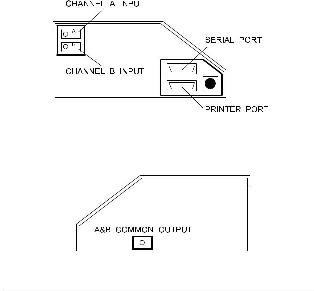
On its front panel, the Infutest provides a menu-driven user interface which is implemented with a liquid crystal display (LCD) and four multi-function, softwaredefined push buttons ("soft keys"). The left panel of the Infutest (Figure 1) provides both a Centronix-standard parallel port (DB25 female) for connection to an Epson FX Series or compatible printer, and a RS-232 serial port (DB25 male) for data output to a personal computer or other data collection instrument. Also located on the left panel are two Delrin twistlock, self -sealing connectors which serve as a fluid inputs for Channels A and B. Fluid exits the Infutest via a Delrin twistlock connector which provides the Channel A & B common output (Figure 2). Inputs for pump Nurse Call signals and outputs for triggering PCA pumps are provided on the Infutest rear panel
(Figure 3).
Figure 1 - Infutest left panel
Figure 2 - Infutest right panel
Overview/Chapter 2 # Page 10

INFUTEST 2000E OPERATING MANUAL
Figure 3 - Infutest rear panel
The Infutest incorporates a time/date clock and a data logger capable of storing up to 900 flow measurements and 700 occlusion pressure measurements per channel. A "flow measurement" comprises elapsed time (in hours, minutes and seconds), flow rate, average flow, total effused volume and back pressure for the Single Rate, Dual-Rate and PCA Pump Tests. A “pressure measurement” comprises elapsed time, occlusion pressure and Nurse Call Alarm status for the Occlusion Pressure Test.
When an RSM is connected to the Infutest, the data log is initialized to 450 flow and 350 pressure measurements for each of the four channels.
The Infutest also provides a Summary for each channel. A Summary condenses the raw data obtained from a test into a few important values, such as the average flow measured during the test, and the total volume of fluid that was effused. An Occlusion Pressure Summary is also included to provide a synopsis of Occlusion Pressure Test results.
Upon completion of a test, contents of the channel Data Log, the channel Summary, or both may be output to a printer or downloaded to a personal computer via the serial port. Multiple copies of the test results may be output in succession, and each copy may be directed to either the printer or the serial port at the user's option.
Overview/Chapter 2 # Page 11

INFUTEST 2000E OPERATING MANUAL
To accommodate long-term testing or special testing needs, the Infutest may be controlled remotely via RS-232C using the Infutest Remote Control (IRC) command set (see Section 6). This command set allows the Infutest to be setup and controlled by a user designed program. Data may be collected in real-time, allowing long-term testing and data collection.
The Infutest incorporates a non-volatile memory which allows the instrument to be disconnected from the line and transported without losing previously acquired test results. At power-up, the user may select to view or output the contents of a channel’s Data Log or Summary, which are both retained in the non-volatile memory. Initial test settings are also preserved when the AC supply is disconnected.
A Windows based software accessory, available from Datrend Systems (the Infutest Data Transfer Program - DTP), facilitates transfer of test results from the Infutest to a personal computer, and conversion of Infutest Data Log and Test Summary Report files to numeric data files suitable for importing into most spreadsheet or database programs. DTP also has the ability to graphically display and print flow versus time graphs and trumpet (error bounds) graphs.
Overview/Chapter 2 # Page 12

INFUTEST 2000E OPERATING MANUAL
2.2 Description of Test Procedures
Each channel of the Infutest is capable of making the following measurements:
iFlow Rate ranging from 0.1 up to 1200 milliliters per hour;
iiEffused Volume up to 9999 milliliters;
iiiPulsatile Flow ranging from 5 up to 1200 milliliters per hour;
ivKeep-Vein-Open (KVO) Rate following primary delivery;
vPCA pump Delivery Rate during bolus infusion, ranging from 0.1 up to 170 milliliters per hour;
viBolus Volume delivered by PCA pump;
viiNumber of Boluses delivered from PCA pump, up to 255;
viiiLockout Time between PCA pump bolus deliveries, in minutes and seconds;
ixPCA pump Basal Rate following bolus delivery (using Dual-Rate Test);
xBack Pressure applied to infusion device, up to 300 mmHg;
xiOcclusion Pressure produced by infusion device, up to 2586 mmHg (50 psi); and
xiiStatus of Nurse Call Alarm from infusion device (ON or OFF).
The above measurements are organized into four basic test protocols. These test protocols are:
2.2.1Single Rate Test
Use the Single Rate Test to evaluate the basic performance of all medical
infusion devices. The Single Rate Test measures Flow Rate (instantaneous and average), Effused Volume, and Back Pressure.
In addition to accommodating continuous flow infusion devices, the Single Rate test also incorporates automated detection and averaging of pulsatile flow for increased measurement accuracy of bolus-discharge and other non-continuous pumping devices.
Overview/Chapter 2 # Page 13

INFUTEST 2000E OPERATING MANUAL
2.2.2Dual Rate Test
Use the Dual-Rate Test to evaluate infusion devices capable of primary/secondary delivery or delivery "piggybacking", that is, delivery of a first preset volume at a first rate followed by delivery of a second preset volume at a second rate. The Dual-Rate Test measures Flow Rate (instantaneous and average), Effused Volume, and Back Pressure for each delivery programmed into the Dual-Rate pump.
Also use the Dual-Rate Test to evaluate Keep-Vein-Open (KVO) operation and
PCA Bolus-Plus-Basal mode delivery with infusion devices which incorporate
these features.
2.2.3PCA Pump Test
Use the PCA Pump Test to evaluate the basic performance of Patient-Controlled infusion devices. The PCA Pump Test measures Flow Rate (instantaneous and average) and Bolus Volume for each bolus delivery, the Lockout Time between bolus deliveries, and the Number of Boluses delivered during the test. Back Pressure is also measured.
2.2.4Occlusion Pressure Test
Use the Occlusion Pressure Test to measure the maximum pressure generated by an infusion device when its output is occluded. Also use the Occlusion Pressure Test to check the operation of the Nurse Call Alarm on pumps which incorporate this feature.
Overview/Chapter 2 # Page 14

INFUTEST 2000E OPERATING MANUAL
2.3 Test Fluids
The following test fluids are acceptable for use with the Infutest:
1.DISTILLED WATER
2.CLEAN DOMESTIC WATER (i.e. "tap water")
Common distilled water is the preferred test fluid. If domestic water is employed, occasional flushing with distilled water may be required following use, depending on hardness and quality of the local water. The test fluid should be colourless and should not contain visible particulate matter. An agent for reducing surface tension of the test fluid is normally not required for routine use. However a wetting agent, such as Jet Dry, may be added if required. In the case of Jet Dry, a concentration of 1.0 ml per litre of test fluid is recommended as a starting point. Wetting agent concentration may have to be varied depending the purity of the test fluid.
IMPORTANT:
THE USE OF SALINE SOLUTION AS A TEST FLUID IS STRONGLY DISCOURAGED, AND WILL VOID THE WARRANTY. IN THE EVENT SALINE SOLUTION IS ACCIDENTALLY USED, THE INFUTEST SHOULD BE FLUSHED WITH DISTILLED WATER.
DO NOT USE DEXTROSE IN WATER (eg. D5W , D25W) OR OTHER VISCOUS TEST FLUIDS WITH THE INFUTEST. USE OF SUCH FLUIDS WILL VOID THE WARRANTY.
If the instrument is in daily use, both channels should be kept primed between tests provided that distilled water or low hardness domestic water is employed. If the instrument is to be stored for several months or transported, fluid should be drained from the unit by forcing air into each channel input with a large syringe while the alternate input is blocked. The instrument should then be carefully blown out from the A and B inputs to the common output using clean, dry compressed air.
For the remainder of this manual, the test fluid is assumed to be distilled water or lowhardness domestic water, and is referred to generically as "water".
Overview/Chapter 2 # Page 15

INFUTEST 2000E OPERATING MANUAL
IMPORTANT:
IV sets which have or may have come in contact with saline or dextrose or other IV fluids should not be used on the Infutest. If an administration set must be re-used (i.e. as part of an incident investigation), ensure the set has been flushed out thoroughly with clean water before connecting the set to the Infutest. Most IV fluids contain salts and sugars which can degrade and potentially ruin the high-precision flow sensors inside the Infutest.
It is always best to use a new administration set when testing a pump. However, the same administration set may be re-used to test several pumps provided the set is primed only with distilled or “sterile” water. Change IV set per the manufacturer’s recommendations to ensure that test results reflect clinical use of the infusion device.
Overview/Chapter 2 # Page 16

INFUTEST 2000E OPERATING MANUAL
Set-up
This chapter describes the initial set-up of the Infutest, describes the basic
fluid connections, fluid priming, and serial and parallel output
connections.
3. INITIAL SET-UP
3.1Connections
a.Place the instrument on a stable, horizontally level surface. Connect electrical power to the unit by inserting the power cable into the rear panel receptacle (Figure 3) and connecting the cable to a grounded outlet.
b.Connect the input tubing set (consisting of the IEC recommended 21 gauge flow restrictor, three-way stop cock, and extension set) to the Channel A fluid input (Figure 1, Figure 4). Similarly, connect the second input tubing set to Channel B. This arrangement is recommended for proper instrument operation.
c.Connect the output extension set to the Channel A & B common output (Figure 2, Figure 7). The A & B Output should drain into a collection vessel of appropriate volume ideally located on the bench near the Infutest. A small (250 to 500 ml) beaker will suffice for most test situations.
The collection vessel should not be located more than 36" below the level of the A & B Output. This will prevent a vacuum from being applied to the Infutest which could damage the internal pressure sensors, or cause a pressure zero error when the Infutest is powered up.
Refer to the instructions in Appendix A if a Back Pressure is to be applied to the Infutest to oppose
the flow from the infusion device.
Set-up/Chapter 3 # Page 17

INFUTEST 2000E OPERATING MANUAL
3.2 Priming
Figure 4, Figure 5 and Figure 6 on the following page show the three possible positions of the stop cock connected to a channel input. As illustrated, the three positions are referred to as ON, PRIME or FLUSH, and OFF.
Figure 4 - Connection of stop cock to channel input, channel ON.
Figure 5 - Stop cock position for priming / flushing
Set-up/Chapter 3 # Page 18
Loading...