

DATEL, Inc., Mansfield, MA 02048 (USA) • Tel: (508)339-3000, (800)233-2765 Fax: (508)339-6356 • Email: sales@datel.com • Internet: www.datel.com
Single Output
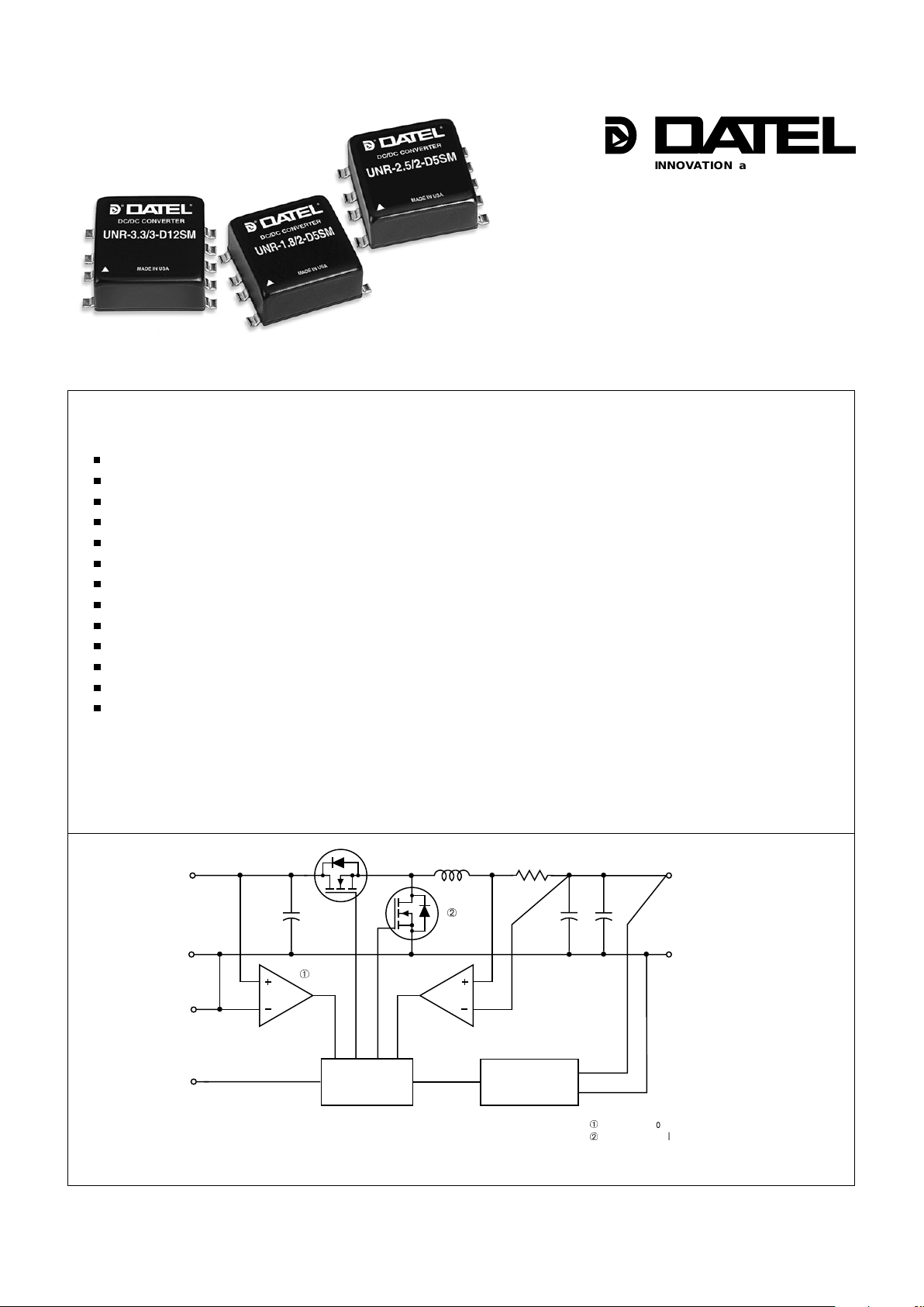
UNR SM Series
Features
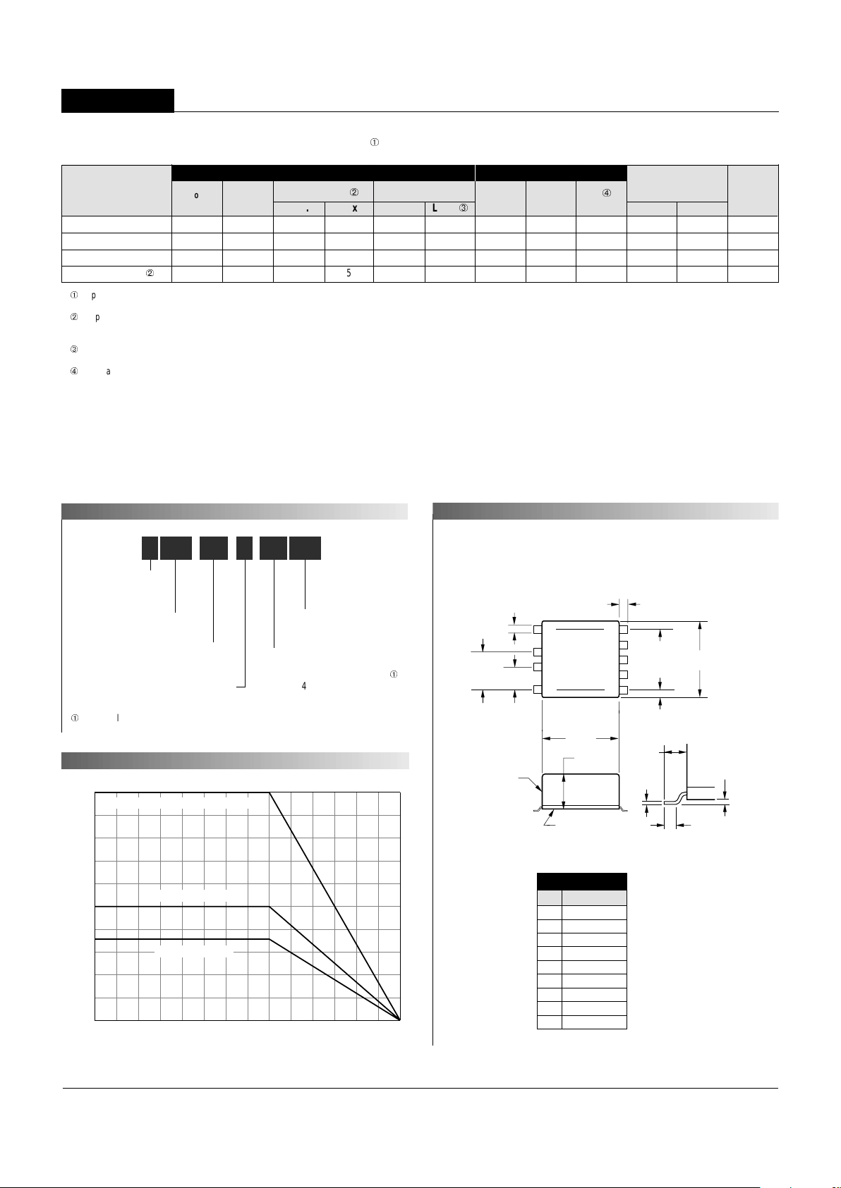
Figure 1. Simplified Schematic
Surface-Mount, Non-Isolated
1.8/2.5/3.3V, 3.6-10W DC/DC Conv e rters
n
n
n
n
n
n
n
n
n
n
n
n
n
INNOVATION and EX C ELL E N C E
®
®
DA TEL's ne w 3.6-10W UNR SM Series consists of non-isolated, 5V -to-1.8V (2A),
5V-to-2.5V (2A), 5V-to-3.3V (3A), and 12V-to-3.3V (3A) DC/DC converters in
miniature, 1" x 1" surface-mount packages. The "gull-wing" packages (with metal
shells and non-conductive plastic baseplates) weigh a mere 17 grams and can
withstand temperatures up to +235°C. They are compatible with virtually all contemporary pick-and-place and solder-reflow processes.
The true benefits of distributed power will ultimately be realized only when every
low-voltage, high-current CPLD , ASIC, DSP, etc. has its own "power plant" right next
to it. With isolated DC/DC converters inevitably residing at the edges of boards in
proximity with backplanes and power buses, the "on-board" proliferation of distributed power will continue with more cost-eff ective, non-isolated de vices. The low-cost,
easy-to-use (no external components required), highly reliable (100% fully automated SMT construction) 3.6-10W UNR SM Series makes this power processing at
the concluding point of use a practical reality today .
These versatile DC/DC's are fully line and load regulated. The y feature useroptional on/off control (for power-sequencing requirements), output current limiting,
and short-circuit protection (foldback technique with auto-recovery). Additionally , the
12V -to-3.3V model offers input undervoltage lockout (at 9.6V). Their impressiv e
guaranteed efficiencies enable all models to deliver their fully rated output power from
–40 to +70°C (ambient) without heat sinking or forced-air cooling.
If you've already considered and rejected the use of inefficient, step-down, linear
regulators, take a look at one of these new s witching buck regulators. Their high
efficiency , ease-of-use, long-term reliability, and over all cost effectiveness will
impress you. Safety agency approvals are currently in progress.
Low cost! High reliability!
1" x 1" x 0.47", SMT package
Gull-wing leads; Standard reflow
Complete; No external components
Outputs: 1.8V/2A, 2.5V/2A, 3.3V/3A
Inputs: 4.75-5.5V , 10.4-13.6V
Guaranteed efficiencies to 87%
Output noise as low as 30mVp-p
T ransient response as quick as 20µsec
–40 to +70°C operation with no derating
On/off control; EMC compliant
IEC950/EN60950/UL1950 pending
Modifications and customs for OEM's
+V
IN
+V
OUT
INPUT
RETURN
ON/OFF
C
ONTROL
OUTPUT
RETURN
CURRENT LIMITING
& S.C. SHUTDOWN
UNDERVOLTAGE
SHUTDOWN
LOGIC
GROUND
REFERENCE &
ERROR AMP
PWM
CONTROLLER
À
À
"D5" models do not have input undervoltage shutdown.
Á
"D5" models employ a more traditional buck-regulator design
in which this FET is replaced with a power Schottky diode.
Á
UNR Series
NON-ISOLATED, 3.6-10W, SURFACE-MOUNT DC/DC CONVERTERS
MECHANICAL SPECIFICATIONS
1.00
(25.40)
0.45
(11.43)
0.055
(1.40)
0.020
(0.51)
0.110
(2.79)
0.015
(0.38)
METAL CASE
INSULATED BASE
4
3
2
1
8
7
6
5
9
0.10
(2.54)
0.110
(2.79)
0.100
(2.54)
0.300
(7.62)
0.500
(12.70)
TOP VIEW
1.00
(25.40)
0.800
(20.32)
4 EQ. SP.@
0.200 (5.08)
Case C17
I/O Connections
Pin Function P24
1N.C.
2 Logic Ground
3 On/Off Control
4N.C.
5 +Output
6N.C.
7 Output Return
8 Intput Return
9 +Input
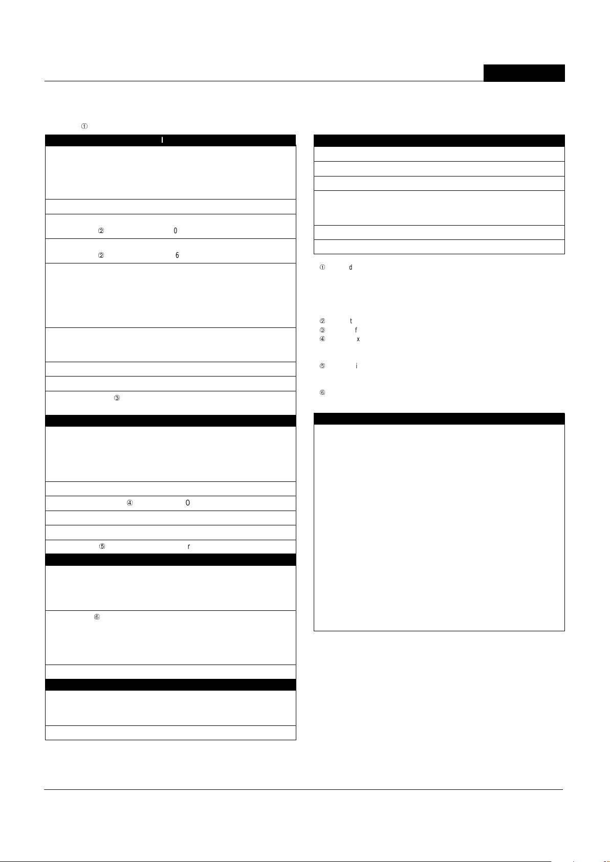
Output Power (Watts)
Ambient Temperature (˚C)
UNR-3.3/3-D5SM, UNR-3.3/3-D12SM
UNR-2.5/2-D5SM
10
9
8
7
6
5
4
3
2
1
0
–400 404550556065707580859095100
UNR-1.8/2-D5SM
TEMPERATURE DERATING
Performance Specifications and Ordering Guide
IOUT
(Amps)
R/N (mVp-p)
Á
Load
Â
VOUT
(Volts)
Package
(Case,
Pinout)
Efficiency
Regulation (Max.)
Line
VIN Nom.
(Volts)
Range
(Volts)
Model
À
T ypical at TA = +25°C under nominal line voltage and full-load conditions, unless otherwise noted. The UNR-1.8/2-D5SM requires an
external 15k
Ω
pull-up resistor between VIN and On/Off Control for normal operation. See On/Off Control for details.
Á
Ripple/Noise (R/N) measured over a 20MHz bandwidth. The UNR-3.3/3-D12SM is specified with an external
22µF input capacitor. All other models are specified with no external I/O capacitors. Output noise on the "D12" model can be
reduced significantly with the addition of external output capacitors. See I/O Filtering.
Â
"D5" models require a minimum 300mA load current to maintain regulation. The "D12" model has no mimimum load requirement.
Listed specs apply from 300mA to full load for "D5" models and from no load to full load for the "D12" model.
Ã
Nominal line voltage, no-load/full-load conditions.
IIN Ã
(mA)
À
Max.
Typ.
Typ.
Min.
UNR-1.8/2-D5SM 1.8 2 40 75 ±0.35% ±0.35% 5 4.5-5.5 30/90 0 77% 79 % C17, P24
UNR-2.5/2-D5SM 2.5 2 30 50 ±0.25% ±0.5% 5 4.75-5.5 40/1180 83% 85% C17, P24
UNR-3.3/3-D5SM 3.3 3 30 45 ±0.4% ±0.5% 5 4.75-5.5 40/2250 86% 88% C17, P24
UNR-3.3/3-D12SM
Á
3.3 3 100 150 ±0.25% ±0.5% 12 10.4-13.6 40/930 87% 89% C17, P24
Output
Input
PART NUMBER STRUCTURE
Non-Isolated
Output Configuration:
U = Unipolar
Nominal Output Voltage:
1.8, 2.5 or 3.3 Volts
Maximum Output Current
in Amps
Input V oltage Range:
D5 = 4.75-5.5 Volts (5V nominal)
À
D12 = 10.4-13.6 Volts (12V nominal)
U NR 2-
/
D5 SM-2.5
Surface-Mount Packaging
À
4.5-5.5 Volts for UNR-1.8/2-D5SM
2
SM ModelsSM Models
SM ModelsSM Models
SM Models
NON-ISOLATED, 3.6-10W, SURFACE-MOUNT DC/DC CONVERTERS
Performance/Functional Specifications
T ypical @ TA = +25°C under nominal line voltage and full-load conditions with no e xternal filtering,
unless noted.
À
Input
Input V oltage Range:
"D5" Models:
UNR-1.8/2-D5SM 4.5-5.5 V olts (5V nominal)
UNR-2.5/2-D5SM, UNR-3.3/3-D5SM 4.75-5.5 Volts (5V nominal)
"D12" Models 10.4-13.6 Volts (12V nominal)
Overvoltage Shutdown None
Start-Up Threshold:
"D12" Models
Á
10.2V typical, 10.4V maximum
Undervoltage Shutdown:
"D12" Models
Á
9.6V typical, 8.2V minimum
Input Current:
Normal Operating Conditions See Ordering Guide
Standby Mode (Off or undervoltage):
UNR-1.8/2-D5SM 20mA typical, 30mA maximum
UNR-2.5/2-D5SM, UNR-3.3/3-D5SM 10mA typical, 20mA maximum
UNR-3.3/3-D12SM 5mA typical, 10mA maximum
Input Ripple Current:
UNR-1.8/2-D5SM, UNR-3.3/3-D12SM 50mArms
UNR-2.5/2-D5SM, UNR-3.3/3-D5SM 150mArms
Input Filter T ype Capacitive
Reverse-Polarity Protection None
On/Off Control (Pin 3)
Â
TTL high (or open) = on, low = off
1.5V typical logic threshold
Output
VOUT Accuracy (50% load):
UNR-1.8/2-D5SM ±1.5% (±27mV) maximum
UNR-2.5/2-D5SM ±1.5% (±37.5mV) maximum
UNR-3.3/3-D5SM ±1.5% (±50mV) maximum
UNR-3.3/3-D12SM ±1% (±33mV) maximum
Temperature Coefficient ±0.02% per °C
Ripple/Noise (20MHz BW)
Ã
See Ordering Guide
Line/Load Regulation See Ordering Guide
Efficiency See Ordering Guide
Current Limiting
Ä
Auto-recovery
Dynamic Characteristics
Transient Response (50% load step):
UNR-1.8/2-D5SM 20µsec to ±0.5% of final value
UNR-2.5/2-D5SM, UNR-3.3/3-D12SM 30µsec to ±1% of final value
UNR-3.3/3-D5SM 40µsec to ±1% of final value
Start-Up Time:
Å
VIN to VOUT: "D5" Models 100msec typical, 120msec maximum
"D12" Models 13msec typical, 20msec maximum
On/Off to V
OUT: "D5" Models 60msec typical, 120msec maximum
"D12" Models 13msec typical, 20msec maximum
Switching Frequency 200kHz (±30kHz)
Environmental
Operating Temperature (Ambient):
Without Derating –40 to +70°C
With Derating to +100°C (See Derating Curves)
Storage Temperature –40 to +105°C
À
"D5" models require a minimum 300mA load current to maintain specified regulation. "D12"
models have no minimum load requirement. Operating "D5" models under no-load conditions
will not damage these devices, however they may not meet all listed specifications. The
UNR-1.8/2-D5SM requires an external 15
Ω
pull-up resistor between VIN and On/Off Control for
normal operation. See On/Off Control for details. The UNR-3.3/3-D12SM is specifiied with an
external 22µF input capacitor. See I/O Filtering for details.
Á
See Startup Threshold and Undervoltage Shutdown for details.
Â
See On/Off Control for details.
Ã
The 22µF external input capacitor required for the UNR-3.3/3-D12SM should be minimally
rated for 1.5Arms ripple current and 125m
Ω
ESR. Output noise for all models can be further
reduced with the installation of external output capacitors. See See I/O Filtering for details.
Ä
Current limiting initiates at approximately 30% above rated load. Under short-circuit
conditions, output current folds back to approximately 150mA and input current drops to
approximtely 50mA. Both remain at those levels until the short is removed.
Å
See Start-Up Time for details.
Physical
Dimensions 1" x 1" x 0.47" (25 x 25 x 11.9mm)
Shielding None
Case Connection None
Case Material Corrosion-resistant steel with
non-conductive, epoxy-based, black
enamel finish and plastic baseplate
Pin Material Copper, tin plated
Weight 0.6 ounces (17 grams)
Input Voltage:
Continuous:
"D5" Models 7 Volts
"D12" Models 15 Volts
Transient (100msec):
"D5" Models 15 Volts
"D12" Models 24 Volts
Input Reverse-Polarity Protection None
Output Overvoltage Protection None
Output Current Current limited. Devices can
withstand a sustained output
short circuit without damage.
Storage Temperature –40 to +105°C
Lead Temperature (Soldering, 10 sec.) +300°C
These are stress ratings. Exposure of devices to any of these conditions may adversely
affect long-term reliability. Proper operation under conditions other than those listed in the
Performance/Functional Specifications T ab le is not implied.
Absolute Maximum Ratings
3

UNR Series
NON-ISOLATED, 3.6-10W, SURFACE-MOUNT DC/DC CONVERTERS
TECHNICAL NOTES
Return Current Paths
The Input Return (pin 8), Output Return (pin 7) and Logic Ground (pin 2) are all
connected to each other internal to each device. To the extent possible, all load
current should be returned through pin 7 (via low-impedance runs) and all input
current returned through pin 8. Any control signals applied to pin 3 should be
referenced to pin 2. The internal trace leading to pin 2 is not designed to carry
high current. Devices should never be installed in a manner that results in high
current flow through pin 2 (i.e., pins 7 and 8 should never be left open or
attached via high-impedance connections).
Input Fusing
Certain applications and/or safety agencies may require the installation of fuses
at the inputs of power conversion components. Fuses should also be used if the
possibility of sustained, non-current-limited, input-voltage polarity reversals
exists. For D ATEL UNR SM Series 3.6-10 Watt DC/DC Converters, you should
use slow-blow type fuses with values no greater than the following.
Model Number Fuse Va lue
UNR-1.8/2-D5SM 1.5 Amps
UNR-2.5/2-D5SM 2 Amps
UNR-3.3/3-D5SM 3 Amps
UNR-3.3/3-D12SM 1.5 Amps
Start-Up Threshold and Underv oltage Shutdown (UNR-3.3/3-D12SM only)
Under normal start-up conditions, UNR-3.3/3-D12SM devices will not begin to
regulate until the ramping input voltage exceeds the Start-Up Threshold V oltage
(typically 10.2V). Once operating, devices will not turn off until the input voltage
drops below the Undervoltage Shutdown/Lockout limit (typically 9.6V).
Subsequent re-start will not occur until the input is brought back up to the StartUp Threshold. This built-in hysteresis obviously avoids any indeterminate on/off
conditions at a single voltage.
Start-Up Time
For the three "D5" models (that do not have an input turn-on threshold), the V
IN
to VOUT Start-Up Time is the interval between the time a step input is applied to
the device and the fully loaded output voltage enters and remains within its
specified accuracy band.
For the UNR-3.3/3-D12SM, V
IN to VOUT Start-Up Time is the interval between
the time at which a rapidly ramping input voltage crosses the turn-on threshold
point and the fully loaded output voltage enters and remains within its specified
accuracy band. Actual measured times will vary with input source impedance,
external input capacitance, and the slew rate and final value of the input voltage
as it appears to the converter.
The On/Off to V
OUT Start-Up Time assumes the converter is turned off via the
On/Off Control with the nominal input voltage already applied to the converter.
The specification defines the interval between the time at which the converter is
turned on and the fully loaded output voltage enters and remains within its
specified accuracy band.
I/O Filtering and Noise Reduction
All "D5" models of UNR SM Series 3.6-10W DC/DC converters achieve their
rated ripple and noise specifications without the use of external input/output
capacitors. The UNR-3.3/3-D12SM is tested and specified with a single,
external 22µF input capacitor (minimally rated for 1.5Arms ripple current and
120m
Ω
ESR).
In critical applications, input/output ripple/noise may be further reduced by
installing additional external I/O caps. Input capacitors, which function primarily
as energy-storage elements, should be selected for bulk capacitance, low ESR
and high rms-ripple-current ratings. Output capacitors, which function more as
true filter elements, should be selected for bulk capacitance, low ESR, and
appropriate frequency response. All caps should have appropriate voltage
ratings and be mounted as close to the converters as possible. T emperature
variations for all parameters should obviously be taken into consideration.
The most effective combination of external I/O capacitors will be a function of
your line voltage and source impedance, as well as your particular load and
layout conditions. Our Applications Engineers will be happy to recommend
potential solutions and can discuss the possibility of our modifying a given
device’s internal filtering to meet your specific requirements. Contact our
Applications Engineering Group for additional details.
4

SM ModelsSM Models
SM ModelsSM Models
SM Models
NON-ISOLATED, 3.6-10W, SURFACE-MOUNT DC/DC CONVERTERS
260
240
220
200
180
160
140
120
100
80
60
40
20
0
0 30 60 90 120 150 180 210 240 270 300
PRE-HEAT AND TEMPERATURE SOAK
SOLDER
REFLOW
PEAK
TEMP.
235°C
Time (Seconds)
Temperature (°C)
On/Off Control
The On/Off Control pin (pin 3) may be used for remote on/off operation. UNR
SM Series converters are designed so that they are enabled when the control
pin is pulled high or left open (normal mode) and disabled when the control pin is
pulled low (to less than +0.8V relative to Logic Ground, pin 2). As shown in the
figure and table below , each device has an internal pull-up resistor on its On/Off
Control pin whose value and voltage vary with model.
Dynamic control of the on/off function is best accomplished with a mechanical
relay or an open-collector/open-drain drive circuit (optically isolated if appropriate). The drive circuit should obviously be able to sink appropriate current when
activated and withstand appropriate voltage when deactivated.
Applying an external voltage to pin 3 when no input power is applied to the
converter can cause permanent damage to the converter. The on/off control
function, however, is designed such that the converter can be disabled (pin 3
pulled low) while input power is ramping up and then "released" once the
input has stabilized. The time duration between the point at which the converter
is released and its fully loaded output voltage settles to within specified
accuracy can be found in the P erformance/Functional Specifications T able .
Solder Reflow
For UNR SM Series devices, the packages' gull-wing leads are made of
tin-plated (150 microinches) copper. The gull-wing configuration, as opposed to
"J" leads, was selected to keep the solder joints out from under the package
to minimize both heat conduction away from the leads (into the encapsulated
package) and IR shadowing effects. Through a series of experiments, using
8mil-thick, 63/37/2 (lead/tin/silver) solder paste and single-layer test boards, we
have determined an optimal solder-reflow temperature profile as shown in Figure
2. Obviously , your optimal prof ile will be a function of many factors including
paste thickness, board thickness, number of conductive layers, copper weight,
the density of surrounding components, etc.
The profile in Figure 3 should be used as a starting point for your own
experiments. If you'd like , DATEL can provide you with complimentary "dummy"
units to be used in such tests. Under no circumstances should the peak
temperature exceed +235°C for an extended period of time.
As shown in Figure 4, our tests have determined the optimal landing-pad size
to be 160 mils by 130 mils.
Figure 2. Driving the On/Off Control Pin
Figure 3. Optimal Solder Reflow Profile
+INPUT
LOGIC GROUND
9
2
VIP
RIPREP
3
ON/OFF
CONTROL
Internal External Internal
Pull-Up Pull-Up Pull-Up
Model Resistor (RIP) Resistor (REP) Voltage (VIP )
UNR-1.8/2-D5SM 1k
Ω
15k
Ω
1.8V
UNR-2.5/2-D5SM 1k
Ω
N.A. 2.5V
UNR-3.3/3-D5SM 1k
Ω
N.A. 3.3V
UNR-3.3/3-D12SM 10k
Ω
N.A. VIN
Figure 4. PC Board Land Pattern
0.130*
(3.30)
0.015
(0.38)
0.100**
(2.54)
* PAD DIMENSION
** LEAD DIMENSION
0.160*
(4.06)
0.110**
(2.79)
5

UNR Series
NON-ISOLATED, 3.6-10W, SURFACE-MOUNT DC/DC CONVERTERS
TYPICAL PERFORMANCE CURVES
Efficiency vs. Output Current and Input V oltage
82
81
80
79
78
77
76
75
74
73
UNR-1.8/2-D5SM
(Guaranteed efficiency = 77% at V
IN
= 5V and I
OUT
= 2A)
0.5 0.8 1.1 1.4 1.7 2
+1.8V Output Current (Amps)
V
IN
= 5V
V
IN
= 5.5V
V
IN
= 4.5V
Efficiency (%)
87
86
85
84
83
82
81
80
79
78
UNR-2.5/2-D5SM
(Guaranteed efficiency = 83% at V
IN
= 5V and I
OUT
= 2A)
0.5 0.8 1.1 1.4 1.7 2
+2.5V Output Current (Amps)
V
IN
= 4.75V
V
IN
= 5.5V
V
IN
= 5V
Efficiency (%)
91
90
89
88
87
86
85
84
83
82
UNR-3.3/3-D5SM
(Guaranteed efficiency = 86% at V
IN
= 5V and I
OUT
= 3A)
0.5 1 1.5 2 2.5 3
+3.3V Output Current (Amps)
V
IN
= 4.75V
V
IN
= 5.5V
V
IN
= 5V
Efficiency (%)
92
89
86
83
80
77
74
71
68
65
UNR-3.3/3-D12SM
(Guaranteed efficiency = 87% at V
IN
= 12V and I
OUT
= 3A)
0.5 1 1.5 2 2.5 3
+3.3V Output Current (Amps)
V
IN
= 10.4V
V
IN
= 13.6V
V
IN
= 12V
Efficiency (%)
6

SM ModelsSM Models
SM ModelsSM Models
SM Models
NON-ISOLATED, 3.6-10W, SURFACE-MOUNT DC/DC CONVERTERS
DATEL’s world-class design, development and manuf acturing team stands
ready to work with you to deliver the exact power converter you need for your
demanding, large volume, OEM applications. And ... we’ll do it on time and
within budget!
Our experienced applications and design staffs; quick-turn prototype capability;
highly automated, SMT assembly facilities; and in-line SPC quality-control
techniques combine to give us the unique ability to design and deliver any
quantity of power conv erters to the highest standards of quality and reliability.
We have compiled a large library of DC/DC designs that are currently used in a
variety of telecom, medical, computer, railw ay , aerospace and industrial
applications. We may already have the converter you need.
Contact us. Our goal is to provide you the highest-quality , most cost-eff ective
power converters available.
CUSTOM CAPABILITIES
DATEL makes no representation that the use of its products in the circuits described herein, or the use of other technical information contained herein, will not infringe upon existing or future patent rights. The descriptions
contained herein do not imply the granting of licenses to make, use, or sell equipment constructed in accordance therewith. Specifications are subject to change without notice. The DATEL logo is a registered DATEL,
Inc. trademark.
DATEL (UK) LTD. Tadley, England Tel: (01256)-880444
DATEL S.A.R.L. Montigny Le Bretonneux, France Tel: 01-34-60-01-01
DATEL GmbH München, Germany Tel: 89-544334-0
DATEL KK Tokyo, Japan Tel: 3-3779-1031, Osaka Tel: 6-354-2025
DATEL, Inc. 11 Cabot Boulevard, Mansfield, MA 02048-1151
Tel: (508) 339-3000 (800) 233-2765 Fax: (508) 339-6356
Internet: www.datel.com Email: sales@datel.com
Data Sheet Fax Back:(508) 261-2857
DS-0442 8/99
INNOVATION and EX C ELL E N C
E
®
®
ISO 9001 REGISTERED
7
If you’re designing with EMC in mind, please note that all of DA T EL’s
3.6-10 Watt UNR SM Series DC/DC Converters have been characterized for
radiated and conducted emissions in our new EMI/EMC laboratory . T esting is
conducted in an EMCO 5305 GTEM test cell utilizing EMCO automated EMC
test software. Radiated emissions are tested to the limits of FCC Part 15,
Class B and CISPR 22 (EN 55022), Class B. Correlation to other specifications
can be supplied upon request. Radiated emissions plots to FCC and CISPR 22
for model UNR-3.3/3-D5SM appear below . Published EMC test reports are
available f or each model number . Contact DATEL's Applications Engineering
Department for more details.
EMI Radiated Emissions
80
70
60
50
40
30
20
10
0
–10
–20
100
1000
Frequency (MHz)
100
1000
Frequency (MHz)
Radiated Emissions (dBµV/M)
80
70
60
50
40
30
20
10
0
–10
–20
Radiated Emissions (dBµV/M)
UNR-3.3/3-D5SM Radiated Emissions
FCC Part 15 Class B, 3 Meters
Converter Output = 3.3Vdc @ 2.7 Amps
UNR-3.3/3-D5SM Radiated Emissions
EN 55022 Class B, 10 Meters
Converter Output = 3.3Vdc @ 2.7 Amps
Radiated Emissions
Radiated Emissions
FCC Class B Limit
EN 55022 Class B Limit
 Loading...