

DATEL, Inc., Mansfield, MA 02048 (USA) · Tel: (508)339-3000, (800)233-2765 Fax: (508)339-6356 · Email: sales@datel.com · Internet: www.datel.com
Single Output
UNR Series
Features
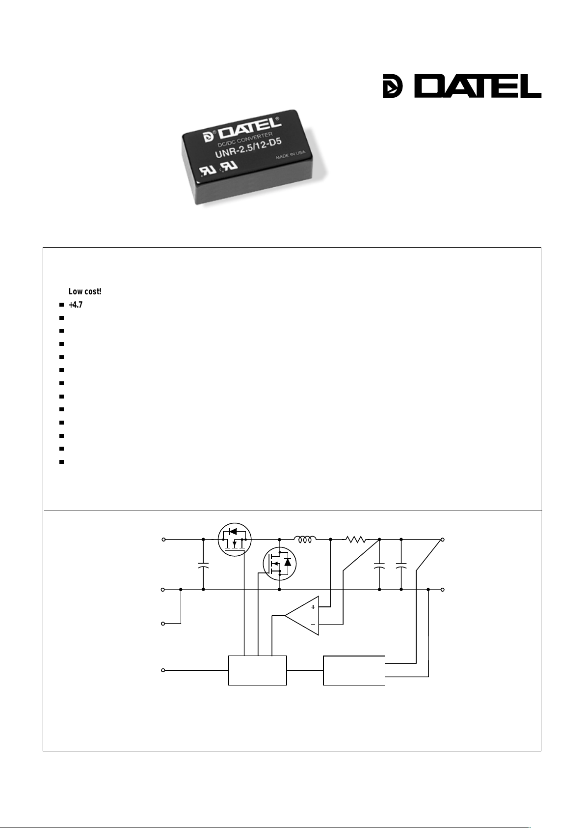
Figure 1. Simplified Schematic
Non-Isolated, 5V -to-2.5V
12 Amp, DC/DC Converters
As supply voltages trend lower and load currents increase, centralized power
becomes more impractical. The tight accuracy , low noise and quick transient
response demanded by today’s low-voltage CPU’s, ASIC’s and DSP’ s make power
processing at the "point of use" the only viable solution. As voltages decrease much
below 3.3V, the task of designing your own circuit to efficiently derive low-voltage
power from higher-voltage buses (5V , 12V, 48V, etc.) becomes significantly more
challenging.
When you are designing power-hungry 2.5V partitions or boards, consider
DATEL’s new UNR-2.5/12-D5. This non-isolated, 5V -to-2.5V DC/DC delivers a full
12 Amps at an impressive 87% efficiency. Packaged in a 1" x 2" x 0.44" metal case,
the converter exploits synchronous rectification, planar magnetics and 100%
automatic SMT assembly to bring you an incomparable 30 Watts of 2.5V power.
The UNR-2.5/12-D5 delivers full power over the –40 to +50°C temperature
range without heat sinking or forced-air cooling. It is fully line (±0.1%) and load
(±0.5%) regulated and features low noise (40mVp-p) and quick (30µsec) transient
response. The unit offers remote on/off control, and it can withstand a sustained
output short circuit with full recovery to rated accuracy.
Designing your own 2.5V step-down buck regulator may be practical for lowpower applications. When you need 12 Amps, the task becomes significantly more
time consuming. Consider that the high efficiency, ease-of-use, and overall cost
effectiveness of DA TEL’s new 2.5V UNR Series make the quick solution the best
solution.
■
n
n
n
n
n
n
n
n
n
n
n
n
n
Low cost!
+4.75V to +5.5V input
+2.5V (±25mV), 12 Amp output
200kHz, synchronous-rectifier topology
High efficiency, 87%
Low output noise, 40mVp-p
Quick transient response, 30µsec
–40 to +50°C operation with no derating
Highly reliable, 100% SMT construction
Remote on/off control
Output short-circuit protection
1" x 2" metal package; EMC compliant
IEC950/EN60950/UL1950 pending
Modifications and customs for OEM’s
INNOVATION and EX C ELL E N C E
®
®
+V
IN
+V
OUT
INPUT
RETURN
ON/OFF
C
ONTROL
OUTPUT
RETURN
CURRENT LIMITING
& S.C. SHUTDOWN
LOGIC
GROUND
PWM
CONTROLLER
REFERENCE &
ERROR AMP
Signals applied to the On/Off Control are referenced to Logic Ground
which is internally connected to Input/Output Return. The Logic Ground
pin is not designed to carry heavy current. Do not install units with the
Return pins open or connected via high-impedance runs.

UNR Series
NON-ISOLATED, 30W, SINGLE OUTPUT DC/DC CONVERTERS
MECHANICAL SPECIFICATIONS
Input Voltage 7 Volts
Output Current Current limited. Devices can
withstand a sustained output short
circuitwithout damage.
Storage Temperature –40 to +105°C
Lead Temperature (soldering, 10 sec.) +300°C
These are stress ratings. Exposure of devices to any of these conditions may adversely
affect long-term reliability . Proper operation under conditions other than those listed in the
Performance/Functional Specifications T able is not implied.
Absolute Maximum Ratings
The On/Off Control pin has an internal 5kW pull-up resistor to +VIN. It can
be driven with any logic circuit capable of meeting the following drive requirements. Logic "0" = 0 to +0.8V. Logic "1" = +2.0V to +VIN. IIH (@VIN = +2.0V) =
–0.7mA. I
IL (@VIN = 0V) = –1.1mA. Open collector logic or a single NPN drive
transistor can be used. The drive circuit should be rated for more than 5.5V .
Applying a voltage to pin 2 when no input power is applied to the converter can
cause permanent damage to the converter.
On/Off Control Functionality
ORDERING INFORMATION
I/O Connections
Pin Function P9
1 Logic Ground
2 On/Off Control
3 +Output
4 Output Return
5 Input Return
6 +Input
Note:
The case is connected to
pin 5 (Input Return).
0.10
(2.54)
0.800
(
20.32)
0.300
(7.62)
1.800
(45.72)
0.200
(5.08)
1.00
(25.40)
BOTTOM VIEW
1
2
3
4
6
0.10
(2.54)
5
0.400
(10.16)
METAL CASE
INSULATED BA S
E
2.00
(50.80)
0.44
(11.18)
0.20 MIN
(5.08)
UNR-2.5/12-D5 Non-Isolated, 5V-to-2.5V, 30 Watt, DC/DC Converter
Performance/Functional Specifications
DATEL makes no representation that the use of its products in the circuits described herein, or the use of other technical information contained herein, will not infringe upon existing or future patent rights. The descriptions contained herein
do not imply the granting of licenses to make, use, or sell equipment constructed in accordance therewith. Specifications are subject to change without notice. The DATEL logo is a registered DATEL, Inc. trademark.
DATEL (UK) LTD. Tadley, England Tel: (01256)-880444
DATEL S.A.R.L. Montigny Le Bretonneux, France Tel: 01-34-60-01-01
DATEL GmbH München, Germany Tel: 89-544334-0
DATEL KK Tokyo, Japan Tel: 3-3779-1031, Osaka Tel: 6-354-2025
DATEL, Inc. 11 Cabot Boulevard, Mansfield, MA 02048-1151
Tel: (508) 339-3000 (800) 233-2765 Fax: (508) 339-6356
Internet: www.datel.com Email: sales@datel.com
Data Sheet Fax Back: (508) 261-2857
DS-0435A 6/99
INNOVATION and EX C ELL E N C
E
®
®
Case C5B
➀
These devices have no minimum load requirements and will regulate under no-load conditions.
➁
Achieving specified performance requires the installation of an external 470µF input capacitor
with an ESR of 20m
W
and an rms ripple current rating of 6 Amps, as well as an external 22µF
output capacitor with an ESR of 200m
W
or less.
➂
No-load/full-load conditions. When the unit is off, the input "standby" current is typically 10mA.
➃
See On/Off Control Functionality.
➄
Output noise may be reduced by installing additional external capacitors across the output
terminals. Caps should be selected for low ESR (typically 60m
W
) and located as close to the
unit as possible.
➅
Current limiting initiates at approximately 30% above rated load. Under short-circuit conditions,
output current folds back to approximately 1A and remains there until the short is removed.
PINS 1-2: 0.040 ±0.002 DIA. (1.016 ±0.051)
PINS 3-6: 0.062 ±0.002 DIA. (1.575 ±0.051
)
Typical @ TA = +25°C under nominal line voltage and full-load conditions, unless noted.
➀ ➁
Input
Input Voltage Range 4.75-5.5 Volts (5V nominal)
Input Current
➂
0.15/6.9 Amps
Input Filter Type Capacitive
Overvoltage Protection None
Reverse-Polarity Protection None
On/Off Control (Pin 2)
➃
TTL high (or open) = on, low = off
Output
VOUT Accuracy (50% load) ±1% (±25mV) maximum
Temperature Coefficient ±0.02% per °C
Ripple/Noise (20MHz BW)
➄
40mVp-p typical, 80mVp-p maximum
Line/Load Regulation ±0.1% maximum/±0.5% maximum
Efficiency 87% typical, 84% minimum
Current Limiting
➅
Auto-recovery
Dynamic Characteristics
Transient Response (50% load step) 30µsec to ±1% of final value
Switching Frequency 200kHz (±20kHz)
Environmental
Operating Temperature (Ambient):
Without Derating –40 to +50°C
With Derating to +100°C (Straight line to 0 Watts)
Storage Temperature –40 to +105°C
.Physical
Dimensions 2" x 1" x 0.44" (51 x 25 x 11.2mm)
Shielding 5-sided
Case Connection Pin 5 (Input Return)
Case Material Corrosion resistant steel with
non-conductive, epoxy-based, black
enamel finish and plastic baseplate
Pin Material Brass, solder coated
Weight 1.6 ounces (45.4 grams)
ISO-9001 REGISTERED
 Loading...