


DATEL, Inc., Mansfield, MA 02048 (USA) • Tel: (508)339-3000, (800)233-2765 Fax: (508)339-6356 • Email: sales@datel.com • Internet: www.datel.com
INNOVATION and EX C ELL E N C E
®
®
Single Output
UMP Models
High-Efficiency, Smaller-Package
25-40 Watt, DC/DC Converters
Features DATEL’s new UMP Models are fully potted, 25-40 Watt DC/DC converters
designed to meet UL1950 and EN60950 safety standards. The combination of the
UMP's higher efficiencies and thermally conductive potting compound enables
these devices to achiev e higher operating temperatures without derating. The
2" x 3" UMP "footprint" conforms with the standard pinout and pin geometries of
most 3" x 3" devices (a 33% space savings) while delivering as much as 60% more
power (40W vs. 25W).
Applicable to a wide range of telecom, computer and other OEM applications,
UMP Model DC/DC’s operate from four input voltage ranges (10-36V for "Q12"
models, 18-36V for "D24" models, 18-75V for "Q48" models, and 36-75V for "D48"
models). Available output voltages are 5, 12 and 15 Volts.
For reliability and affordability, DATEL exploits contemporary, high-speed,
automatic assembly to construct the UMP’s traditional, field-proven, SMT-on-pcb
designs. Devices employ corrosion-resistant metal cases with plastic headers. Heat
generating transformer cores and power semiconductors are mounted directly to
the cases, which have threaded inserts for add-on heat sinks or pcb mounting.
Devices are specified for –40 to +100°C operation and der ating information is
provided for operation with/without heat sinks and forced air flow.
All devices feature input pi filters, input undervoltage and overvoltage shutdown,
output overvoltage protection, output current limiting, and thermal shutdown. UL,
CSA, EN and IEC compliance testing is currently in progress (75V-input devices will
be CE marked) as are full EMI/EMC characterizations. Contact DATEL for the latest
available inf ormation.
Figure 1. Simplified Schematic
COMMO
N
+V
OUT
+V
IN
–V
IN
PWM
CONTROLLER
ISOLATION
REFERENCE &
ERROR AMP
COMPARATORS
UVLO & OVLO
ON/OFF
CONTROL
(
SYNC
)
TRIM
CASE
■
■■
■■
■
■■
■■
■
■■
■■
■
■■
■■
■
■■
■■
■
■■
■■
■
■■
■■
■
■■
■■
■
■■
■■
■
■■
■■
■
■■
■■
■
■■
■■
■
■■
■■
■
Higher operating temperatures
Fully potted
Designed to meet UL1950 and
EN60950 (basic insulation)
mark available (75V-input models)
Fully isolated, 1500Vdc guaranteed
25/30/35/40W output power
Standard pinout! Smaller size!
New 2" x 3" package fits 3" x 3" footprint
5V, 12V or 15V outputs
Four input voltage ranges:
10-36V, 18-36V
18-75V, 36-75V
High efficiency (to 85%)
Input under and overvoltage lockout
V
OUT trim and on/off control
Modifications and customs for OEM's
25-40W, SINGLE OUTPUT DC/DC CONVERTERS
XMP Series
BOTTOM VIEW
2.500
(63.50)
0.27
(6.86)
7
6
8
9
4
1
2
0.22
(
5.59
)
1.200
(30.48)
2.600
(66.04)
0.42
(10.67)
3.04
(77.22)
(4) THREADED INSERTS
#4-40 THD THRU
0.22
(5.59)
3
5
10
0.55
(
13.97)
0.20 MIN.
(5.08)
0.040 ±0.002 DIA.
(1.016 ±0.051)
INSULATED
BASE
METAL
CASE
1.600
(40.64)
4 EQ. SP. @
0.400 (10.16)
2.04
(51.82)
2
UMP Model DC/DC Converters are classified, by output power, into 25, 30,
35 and 40 Watt devices. For the single-output devices listed above, the
maximum available output power is the product of the nominal output voltage
and the maximum allowable output current indicated within the part number
(see Part Number Structure). A UMP-5/6-Q48, for example, can source
6 Amps from its 5V output (over its entire 18-75V input v oltage range)
delivering an output power of 30 Watts. A UMP-5/8-D48 can deliver
40 Watts.
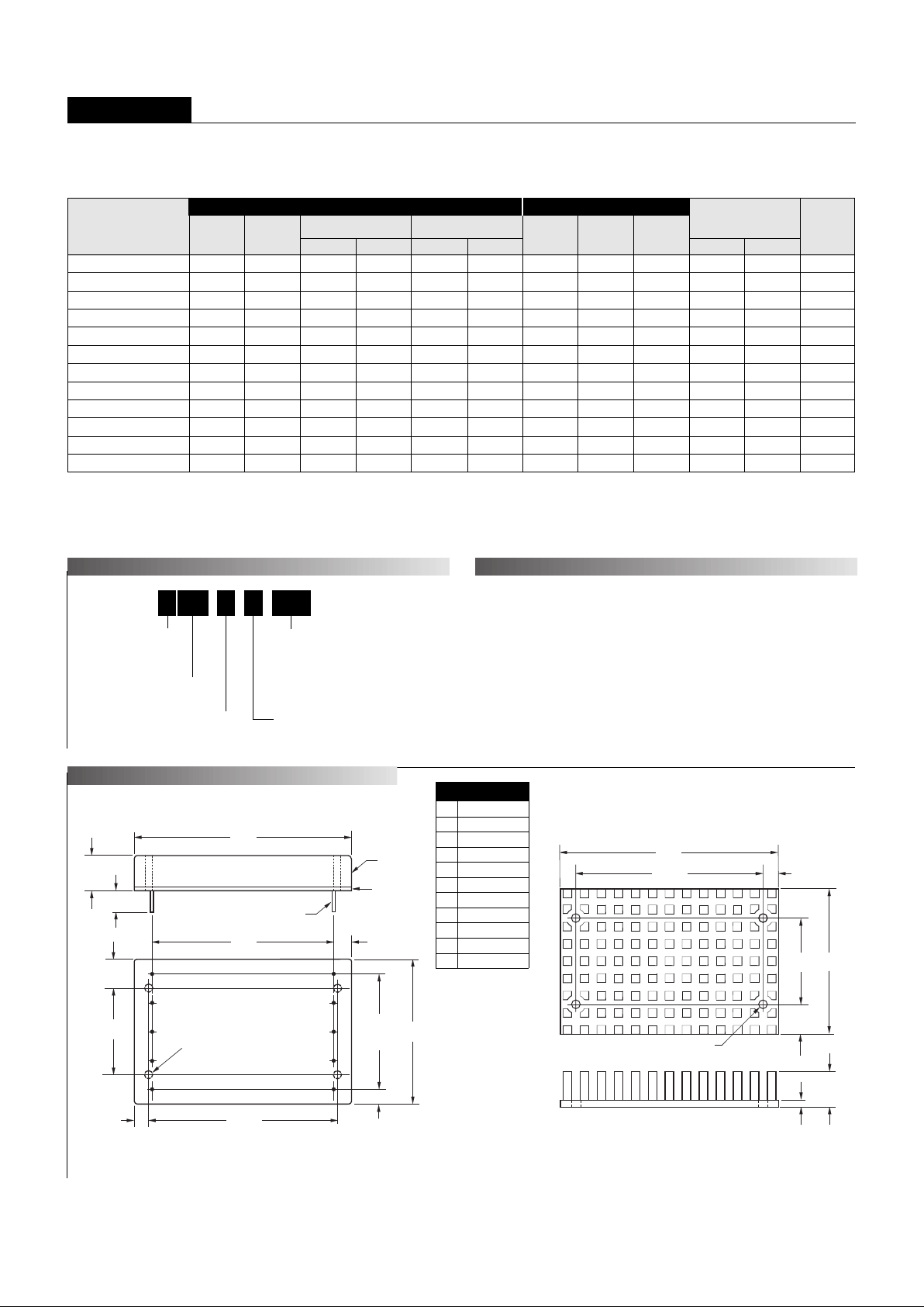
Case C11
I/O Connections
Function P14
No Pin
–Input
+Input
Case
On/Off Control*
No Pin
No Pin
Common
+V
OUT
Trim
Pin
1
2
3
4
5
6
7
8
9
10
Output Configuration:
U = Unipolar
Nominal Output Voltage:
5, 12 or 15 Volts
5U MP 8-/ D48-
Input Volta ge Range:
Q12 = 10-36 Volts (24V nominal)
D24 = 18-36 Volts (24V nominal)
Q48 = 18-75 Volts (48V nominal)
D48 = 36-75 Volts (48V nominal)
Maximum Output Current
in Amps
Fully Potted Metal Package
➀
T ypical at TA = +25°C under nominal line voltage and full-load conditions unless otherwise noted.
➁
Ripple/Noise (R/N) measured over a 20MHz bandwidth.
➂
10 to 100% load.
➃
Nominal line voltage, no-load/full-load conditions.
Performance Specifications and Or dering Guide
R/N (mVp-p)
➁
Load
➂
VOUT
(Volts)
Package
(Case,
Pinout)
Efficiency
Regulation (Max.)
Line
VIN Nom.
(Volts)
Range
(Volts)Model
Input
IIN ➃
(mA)
➀
Max.
Typ.
Typ.
Min.
UMP-5/5-Q12 5 5 75 100 ±0.5% ±1% 24 10-36 50/1366 77% 79% C11, P14
UMP-5/6-Q48 5 6 80 110 ±0.5% ±1% 48 18-75 25/799 79% 80% C11, P14
UMP-5/7-D24 5 7 75 100 ±0.5% ±1% 24 18-36 25/1796 82% 83% C11, P14
UMP-5/8-D48 5 8 75 100 ±0.5% ±1% 48 36-75 25/1026 82% 84% C11, P14
UMP-12/2.1-Q12 12 2.1 100 150 ±0.5% ±1% 24 10-36 50/1326 80% 82% C11, P14
UMP-12/2.5-Q48 12 2.5 100 150 ±0.5% ±1% 48 18-75 30/770 82% 83% C11, P14
UMP-12/3-D24 12 3 100 150 ±0.5% ±1% 24 18-36 25/1825 82% 84% C11, P14
UMP-12/3.3-D48 12 3.3 100 150 ±0.5% ±1% 48 36-75 25/1004 83% 85% C11, P14
UMP-15/1.7-Q12 15 1.7 100 150 ±0.5% ±1% 24 10-36 50/1341 80% 82% C11, P14
UMP-15/2-Q48 15 2 100 150 ±0.5% ±1% 48 18-75 30/770 82% 83% C11, P14
UMP-15/2.5-D24 15 2.5 100 150 ±0.5% ±1% 24 18-36 25/1879 83% 84% C11, P14
UMP-15/2.65-D48 15 2.65 100 150 ±0.5% ±1% 48 36-75 25/1008 83% 85% C11, P14
Optional Heat Sink (Part Number HS-23)
* See note 3 on next page.
IOUT
(Amps)
PART NUMBER STRUCTURE
MECHANICAL SPECIFICATIONS
Output Input
OUTPUT POWER CONSIDERATIONS
2.600
(66.04)
2.00
(50.80)
1.200
(30.48)
3.00
(76.20)
0.40
(10.16)
0.120 DIA. (3.048)
(4 PLACES)
MATERIAL: BLACK ANODIZED ALUMINUM
4 MOUNTING SCREWS AND 0.009 (0.229) THERMAL PAD INCLUDED
TOP VIEW
0.20
(5.08)
0.50
(12.70)
0.10
(2.54)

UMP Models
25-40W, SINGLE OUTPUT DC/DC CONVERTERS
3
Performance/Functional Specifications
T ypical @ TA = +25°C under nominal line v oltage and full-load conditions, unless noted.
➀
Input
Input Volta ge Range:
"Q12" Models 10-36 Volts (24V nominal)
"D24" Models 18-36 Volts (24V nominal)
"Q48" Models 18-75 Volts (48V nominal)
"D48" Models 36-75 Volts (48V nominal)
Undervoltage Lockout:
"Q12" Models 9 Volts
"D24" Models 17 Volts
"Q48" Models 17 Volts
"D48" Models 34 Volts
Input Current See Ordering Guide
Input Filter Type
➁
Pi
Overvoltage Shutdown:
"D24" and "Q12" Models 40 Volts
"D48" and "Q48" Models 80 Volts
Reverse-Polarity Protection Yes (Instantaneous, 6A maximum)
On/Off Control (Pin 5)
➂
TTL high (or open) = on, low = off
Output
VOUT Accuracy (50% load) ±1%, maximum
Temperature Coefficient ±0.02% per °C
Ripple/Noise (20MHz BW)
➁
See Ordering Guide
Line/Load Regulation See Ordering Guide
Efficiency See Ordering Guide
Isolation Voltage 1500Vdc, minimum
Isolation Capacitance 130pF
Current Limiting Continuous, auto-recovery
Overvoltage Protection Zener/transorb clamp, magnetic feedback
Dynamic Characteristics
Transient Response (50% load step) 200µsec max. to ±1.5% of final value
Switching Frequency 165kHz (±10%)
Environmental
Operating Temperature (ambient):
Without Derating –40 to +50°C (model dependent)
With Derating to +100°C (See Derating Cur ves)
Maximum Case Temperature +100°C
Storage Temperature –40 to +105°C
Physical
Dimensions 2.04 x 3.04 x 0.55" (51.8 x 77.2 x 14mm)
Shielding 5-sided
Case Connection Pin 4
Case Material Zinc with a non-conductive, epoxy-based
black enamel finish and plastic baseplate
Pin Material Brass, solder coated
Weight 6 ounces (170 grams)
➀
These converters require a minimum 10% output loading to maintain specified regulation.
Operation under no-load conditions will not damage these devices; howe ver they ma y not
meet all listed specifications.
➁
Application-specific input/output filtering can recommended or perhaps added
internally upon request. Contact DATEL Applications Engineering for details.
➂
Applying voltage to the Control pin with no input power applied can damage the conve rter.
The On/Off function can be replaced with a Sync function. See page 3-48 for more details .
➃
Listed spec is for input-to-output. Input-to-case and output-to-case isolation is 1000Vdc min.
Input Voltage :
"Q12/D24" Models 44 Volts
"Q48/D48" Models 88 Volts
Input Reverse-Polarity Protection Current must be <6A. Brief
duration only. Fusing recommended.
Output Overvoltage Protection
5V Outputs 6.8 Volts, limited duration
12V Outputs 15 Volts, limited duration
15V Outputs 18 Volts, limited duration
Output Current Current limited. Max. current and
short-circuit duration are model
dependent.
Storage Temperature –40 to +105°C
Lead Temperature (soldering, 10 sec.) +300°C
These are stress ratings. Exposure of devices to an y of these conditions ma y adversely
affect long-term reliability. Proper operation under conditions other than those listed in the
Performance/Functional Specifications T able is not implied.
Absolute Maximum Ratings
TECHNICAL NOTES
Floating Outputs
Since these are isolated DC/DC converters, their outputs are "floating."
Users may ground either the Common (pin 8) for normal usage or the
positive side (+Output, pin 9) to effectively reverse the output polarity.
Filtering and Noise Reduction
All UMP 25-40 W att DC/DC Converters achieve their rated ripple and noise
specifications without the use of external input/output capacitors. In critical
applications, input/output ripple and noise may be further reduced by
installing electrolytic capacitors across the input terminals and/or low-ESR
tantalum or electrolytic capacitors across the output terminals. The caps
should be located as close to the power converters as possible. Typical
values are listed in the tables below. In many applications, using values
greater than those listed will yield better results.
To Reduce Input Ripple
"Q12/D24" Models 47µF, 50V
"Q48/D48" Models 10µF, 100V
To Reduce Output Ripple
5V Outputs 47µF, 10V, Low ESR
12/15V Outputs 22µF, 20V, Low ESR
In critical, space-sensitive applications, DATEL may be able to tailor the
internal input/output filtering of these devices to meet your specific requirements. Contact our Applications Engineering Group for additional details.
Input Fusing
Certain applications and/or safety agencies may require the installation of
fuses at the inputs of power conversion components. For DATEL UMP
DC/DC Converters, you should use slow-blow type fuses with values no
greater than the following:
V
IN Range Fuse Value
"Q12" 4A
"D24" 4A
"Q48" 3A
"D48" 2A
 Loading...