

DATEL DMS-20PC-0-5-5RS, DMS-20PC-0-5-5RL, DMS-20PC-0-5-5RH, DMS-20PC-0-5-5GS, DMS-20PC-0-5-24RL Datasheet
DMS-20PC-0/5
0-5V and 0-10V Input
3½ Digit, LED Display
Process Control Monitors
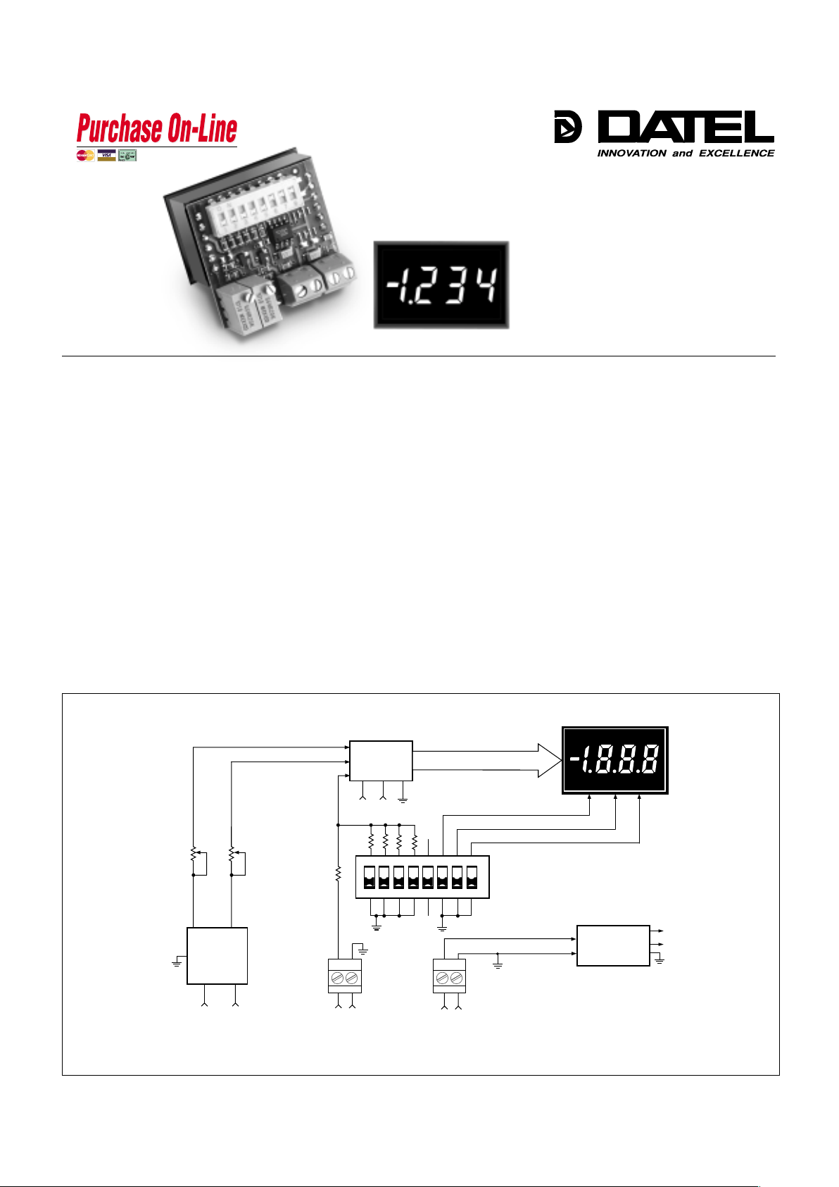
Actual Size
••
••
•
Accepts 0-5V and 0-10V inputs
••
••
•
Large, easy-to-read, 0.37"/9.4mm
LED display
••
••
•
Choice of 5 LED power/color options
••
••
•
High input impedance, 100k
ΩΩ
ΩΩ
Ω
••
••
•
+5V to +40V model draws 9mA typ.
••
••
•
Miniature size: 1.38" x 1.25" x 0.95"
••
••
•
High-quality, 20-turn, span (gain) and
zero (offset) adjustments
••
••
•
DIP-switch selectable range and
decimal points
••
••
•
Vibration-resistant package; Reliable
screw-terminal input connections
••
••
•
Hundreds of different input/readout
combinations
Features
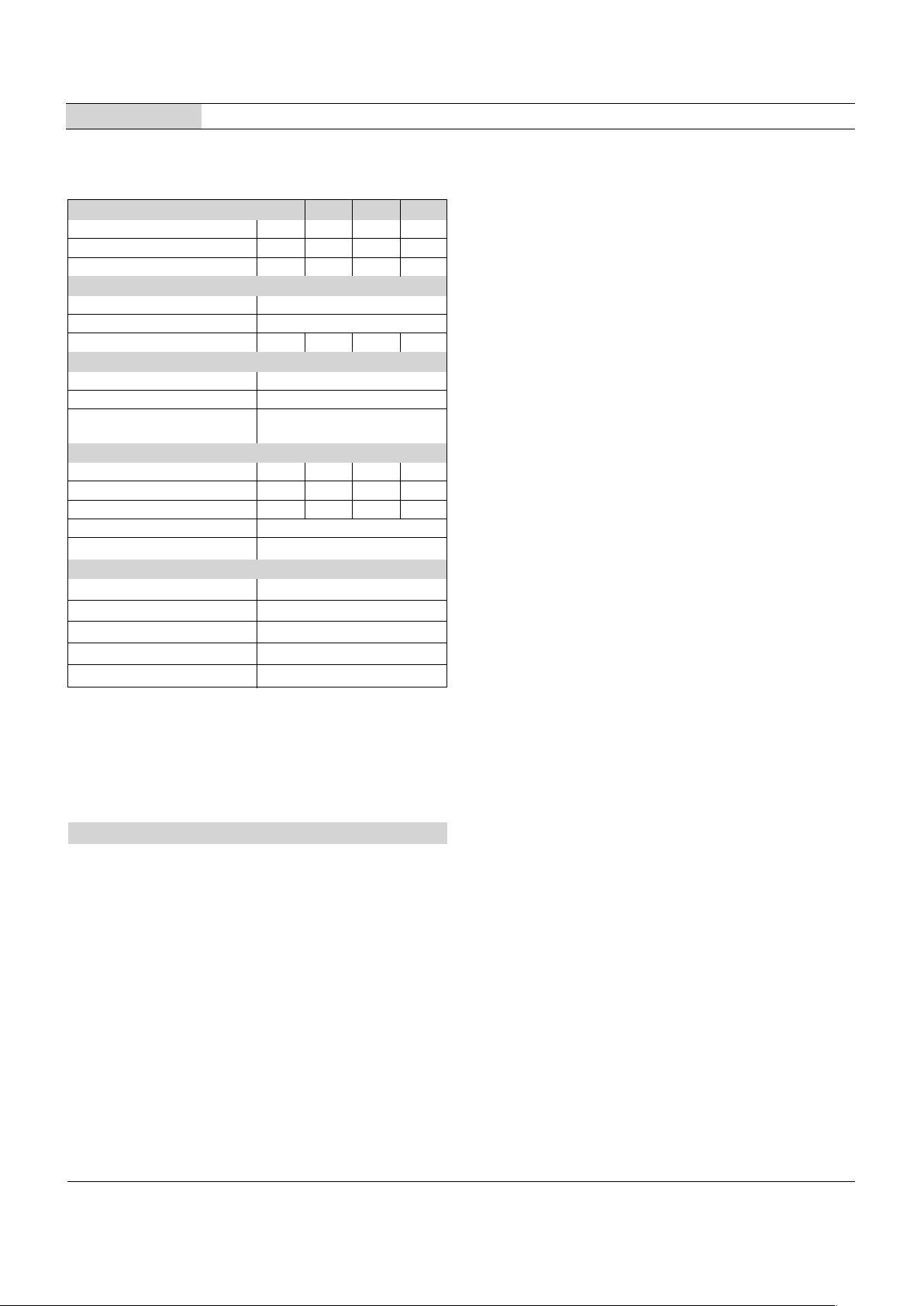
Figure 1. DMS-20PC-0/5 Simplified Schematic
DATEL's DMS-20PC-0/5 Series are the world's smallest, full-featured, 0-5V input
process control monitors. Their large, easy-to-read, 0.37"/9.4mm LED displays are
available in a choice of 4 LED color/intensity options: standard red, standard green,
super-bright red, and low-power red. Two power supply input ranges are also
available: the industr y-standard +5V and a wide-range +5V to +40V (which typically
draws 9mA at +24V).
Gain (span) and offset (zero) adjustments are performed with on-board, precision,
20-turn potentiometers. All decimal-point and range-change selections are made on
an 8-position, vibration-resistant, gold-plated DIP switch. Unlike competitive meters,
there are no jumpers or solder gaps to open or close, and to further enhance
reliability, the entire assembly utilizes 100% soldered connections. Both power-supply
and input-signal connections are made via reliable screw-type terminal blocks.
The DMS-20PC-0/5's DIP switch and potentiometers accommodate hundreds of
input-voltage/output-reading combinations. This practically eliminates the need for
more costly, long-lead-time, factory "specials" in applications which use several
different-range meters. An accessor y bezel assembly––featuring metal fasteners and
a rubber gasket––simplifies panel mounting and also provides excellent resistance
to environmental dust and moisture. All these outstanding features combine to make
the DMS-20PC-0/5 the perfect meter for prototype and OEM, 0-5V input, process
control monitoring.
DATEL, Inc., Mansfield, MA 02048 (USA) • Tel: (508)339-3000, (800)233-2765 Fax: (508)339-6356 • Email: sales@datel.com • Internet: www.datel.com
®®
DP3DP2
DP1
+V
TB2
DMS-20PC-0/5
Signal Input
–
+
TB1
–V
–
+
Zero
Adjust
R3
R7
Gain
Adjust
Band-Gap
Reference
Circuit
HI LO
+5V –5V
3½ Digit
A/D Converter
+5V
–5V
DIP Switches
+5V
DC/DC
Converter
Power Supply Input
DATA
–5V
N.C.
N.C.
ON
1
2345
678
12 12
www.datel.com
DMS-20PC-0/5
0-5V INPUT, 3½ DIGIT, LED DISPLAY PROCESS CONTROL MONITORS
Ordering Information
DMS-20PC-0/5-5RS +5V supply, standard-intensity red LED's
DMS-20PC-0/5-5GS +5V supply, standard-intensity green LED's
DMS-20PC-0/5-5RL +5V supply, low-power red LED's
DMS-20PC-0/5-5RH +5V supply, high-intensity red LED's
DMS-20PC-0/5-24RL +5V to +40V supply, low-power red LED's
DMS-BZL3 Bezel assembly
DMS-BZL4 Bezel assembly with sealing gasket
DMS-20-CP Panel cutout punch
Note: Standard panel-mount applications MUST use either DMS-BZL3 or
DMS-BZL4 bezel assemblies. See Mechanical Specifications section for
cutout/drill dimensions.
As shipped, the DMS-20PC-0/5 is factory calibrated to read
"000" for a 0.0V input and "1999" for a 5.0V input. The following
worst-case procedure assumes the DMS-20PC-0/5 is completely mis-adjusted, i.e., both potentiometers and the DIP
switches are randomly set.
1. Set R7 (full scale span/gain adjust) and R3 (zero/offset
adjust) fully clockwise, roughly 22 turns, and place SW1SW8 to OFF (down position).
2. Select DIP switch setting #1 in Table 1.
3. Apply a precision 0.0V input and adjust R3 until the meter's
display reads "000".
4. Apply a precision 5.0V input and adjust R7 until the meter's
display reads "1999". Repeat steps 3 and 4 to make sure the
adjustments do not affect one another.
5. Select the appropriate decimal point by setting SW6, SW7 or
SW8 to ON (DP1, DP2 or DP3 respectively).
NOTE: The "000" to "1999" display readings referred to in
the instructions above are for illustrative purposes only. If
other display readings such as "000" to "1200" are desired,
refer to the DIP-Switch Settings Tables for SW1-SW4
settings. (SW5 is reserved for future use, it has no affect on
display operation.) The initial setting of R3 and R7 fully
clockwise is recommended in the adjustment procedure for
all the following examples.
Operating and Setup Instructions
➀
The DMS-20PC-0/5 can also be used in most 0-10V applications. See the section
on 0-10V inputs for more information. See Note 3 on Table 1.
➁
INPUT LO (TB1 "–LO") is internally connected to the power return (TB2 "–V").
Overvoltage specifications apply to the INPUT HI (TB1 "+HI") connection.
T echnical Notes
1. Input Configuration: The DMS-20PC-0/5 has its input low terminal
(TB1 "LO") internally connected to the power supply ground terminal
(TB2 "–V"). This connection effectively places the meter's input in a
single-ended configuration. In some applications, single-ended inputs
can cause ground-loop induced errors (the meter's display becomes
unstable or bounces). This occurs because the LED drive currents
flow through both the –V terminal and the signal LO terminal.
If suspected ground-loop errors are encountered, and the input signal
LO terminal is externally connected to –V somewhere else in the
system, try removing the connection to TB1 "LO". Inputs which have
no ground-return connection to –V (commonly referred to as "floating
inputs") must have their most negative potential tied to TB1 "LO".
Please consult DATEL for more information.
Applications which require electrical isolation between the input
signal source and the system power supply must use a separate
transformer-isolated supply to power the meter.
2. Panel Mounting: In most standard through-the-panel installations,
the DMS-20PC-0/5 must be secured to the panel with either DMSBZL3 or DMS-BZL4 optional bezel assemblies (see the Mechanical
Specifications section and the Ordering Guide for more information).
The metal retaining clip supplied with other DMS-20 Series meters
CAN NOT be used to support the DMS-20PC-0/5.
Performance/Functional Specifications
Typical at TA = +25°C, unless otherwise noted.
Input Min. Typ. Max. Units
Full Scale Input Range
➀
4.9 5.0 5.1 Volts
Input Impedance 100 -- 140 k
Ω
Overvoltage Protection
➀
-- -- ±4 0 Volts
Performance
Sampling Rate 2.5 samples per second
Accuracy (1 minute warm-up) ±0.05%FS ±1 Count
Temperature Drift (0 to +60°C) — ±0.15 ±0.3 C nts / °C
Display
Display Type and Size 3½ Digit LED, 0.37"/9.4mm high
Polarity Indication "–" for negative readings
Overrange Indication "–1_ _ _ " for negative inputs
"1_ _ _ " for positive inputs
Physical/Environmental
Operating Temperature 0 — +60 ° C
Storage Temperature –40 — +75 °C
Humidity (Non-condensing) 0 — 95 %
Case Material Polycarbonate
Weight 0.6 ounces (17 grams)
Power Supply Requirements
DMS-20PC-0/5-5RS +4.75V to +5.25V at 90mA max.
DMS-20PC-0/5-5GS +4.75V to +5.25V at 120mA max.
DMS-20PC-0/5-5RL +4.75V to +5.25V at 15mA max.
DMS-20PC-0/5-5RH +4.75V to +5.25V at 90mA max.
DMS-20PC-0/5-24RL +4.75V to +40V at 15mA max.
2
Order on-line at www .datel.com
 Loading...