

Page 1
4K VIDEO WALL
PROCESSOR 2x2
TWP-10
Instruction Manual
Page 2

Table of Contents
FCC COMPLIANCE STATEMENT ........................................................................................................................ 3
WARNINGS AND PRECAUTIONS ....................................................................................................................... 3
WARRANTY ...................................................................................................................................................... 4
STANDARD WARRANTY ............................................................................................................................................ 4
THREE YEAR WARRANTY ........................................................................................................................................... 4
DISPOSAL ......................................................................................................................................................... 5
1. INTRODUCTION ....................................................................................................................................... 6
FEATURES .............................................................................................................................................................. 6
2. CONNECTIONS AND CONTROLS ............................................................................................................... 7
FRONT PANEL ......................................................................................................................................................... 7
REAR PANEL ........................................................................................................................................................... 7
3. HOW TO SET UP THE TWP-10 .................................................................................................................. 9
4. SOFTWARE CONTROL PROGRAM .......................................................................................................... 10
4.1 START THE SOFTWARE CONTROL PROGRAM .................................................................................................. 10
4.2 PROGRAM INTERFACE ............................................................................................................................... 11
I. Connection Status ............................................................................................................................... 11
II. Quick Setting Selection ........................................................................................................................ 11
III. EDID (Extended Display Identification Data) ................................................................................... 15
IV. Advanced Setting ............................................................................................................................ 17
V. 4K Setting ............................................................................................................................................ 18
VI. IP Configure ..................................................................................................................................... 18
VII. Info .................................................................................................................................................. 19
VIII. Refresh ............................................................................................................................................ 19
5. FIRMWARE UPDATE .............................................................................................................................. 20
6. FREQUENTLY-ASKED QUESTIONS .......................................................................................................... 21
7. DIMENSIONS & WEIGHT ........................................................................................................................ 22
8. SPECIFICATIONS .................................................................................................................................... 23
SERVICE AND SUPPORT .................................................................................................................................. 24
Disclaimer of Product & Services
The information offered in this instruction manual is intended as a guide only. At all times, Datavideo
Technologies will try to give correct, complete and suitable information. However, Datavideo Technologies
cannot exclude that some information in this manual, from time to time, may not be correct or may be
incomplete. This manual may contain typing errors, omissions or incorrect information. Datavideo
Technologies always recommend that you double check the information in this document for accuracy before
making any purchase decision or using the product. Datavideo Technologies is not responsible for any
omissions or errors, or for any subsequent loss or damage caused by using the information contained within
this manual. Further advice on the content of this manual or on the product can be obtained by contacting
your local Datavideo Office or dealer.
2
Page 3

FCC Compliance Statement
This device complies with part 15 of the FCC rules. Operation is subject to the following two
conditions:
(1) This device may not cause harmful interference, and
(2) This device must accept any interference received, including interference that may cause
undesired operation.
Warnings and Precautions
1. Read all of these warnings and save them for later reference.
2. Follow all warnings and instructions marked on this unit.
3. Unplug this unit from the wall outlet before cleaning. Do not use liquid or
aerosol cleaners. Use a damp cloth for cleaning.
4. Do not use this unit in or near water.
5. Do not place this unit on an unstable cart, stand, or table. The unit may fall, causing
serious damage.
6. Slots and openings on the cabinet top, back, and bottom are provided for ventilation. To
ensure safe and reliable operation of this unit, and to protect it from overheating, do not
block or cover these openings. Do not place this unit on a bed, sofa, rug, or similar
surface, as the ventilation openings on the bottom of the cabinet will be blocked. This
unit should never be placed near or over a heat register or radiator. This unit should not
be placed in a built-in installation unless proper ventilation is provided.
7. This product should only be operated from the type of power source indicated on the
marking label of the AC adapter. If you are not sure of the type of power available,
consult your Datavideo dealer or your local power company.
8. Do not allow anything to rest on the power cord. Do not locate this unit where the
power cord will be walked on, rolled over, or otherwise stressed.
9. If an extension cord must be used with this unit, make sure that the total of the ampere
ratings on the products plugged into the extension cord do not exceed the extension
cord rating.
10. Make sure that the total amperes of all the units that are plugged into a single wall
outlet do not exceed 15 amperes.
11. Never push objects of any kind into this unit through the cabinet ventilation slots, as
they may touch dangerous voltage points or short out parts that could result in risk of
fire or electric shock. Never spill liquid of any kind onto or into this unit.
12. Except as specifically explained elsewhere in this manual, do not attempt to service this
product yourself. Opening or removing covers that are marked “Do Not Remove” may
expose you to dangerous voltage points or other risks, and will void your warranty. Refer
all service issues to qualified service personnel.
13. Unplug this product from the wall outlet and refer to qualified service personnel under
the following conditions:
a. When the power cord is damaged or frayed;
b. When liquid has spilled into the unit;
c. When the product has been exposed to rain or water;
d. When the product does not operate normally under normal operating conditions.
Adjust only those controls that are covered by the operating instructions in this
manual; improper adjustment of other controls may result in damage to the unit and
3
Page 4

may often require extensive work by a qualified technician to restore the unit to
normal operation;
e. When the product has been dropped or the cabinet has been damaged;
f. When the product exhibits a distinct change in performance, indicating a need for
service.
Warranty
Standard Warranty
• Datavideo equipment are guaranteed against any manufacturing defects for one year
from the date of purchase.
• The original purchase invoice or other documentary evidence should be supplied at the
time of any request for repair under warranty.
• The product warranty period beings on the purchase date. If the purchase date is
unknown, the product warranty period begins on the thirtieth day after shipment from a
Datavideo office.
• Damage caused by accident, misuse, unauthorized repairs, sand, grit or water is not
covered under warranty.
• Viruses and malware infections on the computer systems are not covered under
warranty.
• Any errors that are caused by unauthorized third-party software installations, which are
not required by our computer systems, are not covered under warranty.
• All mail or transportation costs including insurance are at the expense of the owner.
• All other claims of any nature are not covered.
• All accessories including headphones, cables, and batteries are not covered under
warranty.
• Warranty only valid in the country or region of purchase.
• Your statutory rights are not affected.
Three Year Warranty
• All Datavideo products purchased after July 1st, 2017 are qualified for
a free two years extension to the standard warranty, providing the
product is registered with Datavideo within 30 days of purchase.
• Certain parts with limited lifetime expectancy such as LCD panels, DVD
drives, Hard Drive, Solid State Drive, SD Card, USB Thumb Drive, Lighting, Camera
module, PCIe Card are covered for 1 year.
• The three-year warranty must be registered on Datavideo's official website or with your
local Datavideo office or one of its authorized distributors within 30 days of purchase.
4
Page 5

Disposal
For EU Customers only - WEEE Marking
This symbol on the product or on its packaging indicates that this
product must not be disposed of with your other household waste.
Instead, it is your responsibility to dispose of your waste equipment by
handing it over to a designated collection point for the recycling of waste
electrical and electronic equipment. The separate collection and
recycling of your waste equipment at the time of disposal will help to
conserve natural resources and ensure that it is recycled in a manner that protects human
health and the environment. For more information about where you can drop off your
waste equipment for recycling, please contact your local city office, your household waste
disposal service or the shop where you purchased the product.
CE Marking is the symbol as shown on the left of this page. The letters
"CE" are the abbreviation of French phrase "Conformité Européene"
which literally means "European Conformity". The term initially used was
"EC Mark" and it was officially replaced by "CE Marking" in the Directive
93/68/EEC in 1993. "CE Marking" is now used in all EU official documents.
5
Page 6

1. Introduction
Input Resolution
Output Resolution
720x480@30Hz
640x480@60Hz
1600x1200@60Hz
The TWP-10 4K Video Wall Processor 2x2 is a powerful, cost effective, and truly real time
data/video processor for multiple flat panel displays or projectors. Any setups for the
display layout can be virtually possible with the control software.
The TWP-10 allows the user to input HDMI video up to 4K2K@60Hz 4:4:4. The embedded
scaler converts signals from HDMI source to match the original resolution of monitors, flat
panel displays, projectors and user-selectable output settings up to Widescreen Ultra
eXtended Graphics Array (WUXGA 1920x1200).
The TWP-10 sends the processed video through HDMI interface to the connected monitors /
projectors based on the display layout setup. The layout can be readily modified for various
applications such as digital signage, video broadcast, education and surveillance system as
well as visual effect optimization.
That’s Datavideo, sharing the value!
Features
• Four HDMI outputs with resolution from 640x480 to 1920x1200
• Supports HDMI input from 640x480 to 4K2K@60 (YUV 4:4:4), interlaced or progressive
• HDCP compliant
• Image parameters and layouts are automatically saved in flash memory of the device
and can be recalled for later use
• Several image parameters and layouts can be saved in computers and loaded for later
use
• Firmware upgradable for new features and technology enhancements
• Supports IR remote control
• Software control through USB and Ethernet
• Resize, position, zoom for each HDMI output video
• User-selectable output settings, up to 1920x1200
• Supports remote control of switching between 1x1, 2x2, 1x3 rotate, and 1x4 rotate
modes
• Supports independent input rotation at the resolution up to 1080p
• 4K2K60 (YUV 4:4:4) can be divided and displayed on four 1080p60 TVs (2x2 layout only)
• Supports individual propagation delay on each display to achieve the best visual
perception
• Supported resolutions
720x480@60Hz
720x576@30Hz
720x576@60Hz
1280x720@60Hz
1920x1080@30Hz
1920x1080@60Hz
4K2K@30Hz
4K2K@60Hz (4:2:0 10 bits)
4K2K@60Hz (4:2:2 10 bits)
4K2K@60Hz (4:4:4 8 bits)
720x480@60Hz
720x576@60Hz
800x600@60Hz
1024x768@60Hz
1280x720@60Hz
1280x768@60Hz
1280x960@60Hz
1280x1024@60Hz
1366x768@60Hz
1440x900@60Hz
1680x1050@60Hz
1920x1080@60Hz
1920x1200@60Hz
6
Page 7
2. Connections and Controls
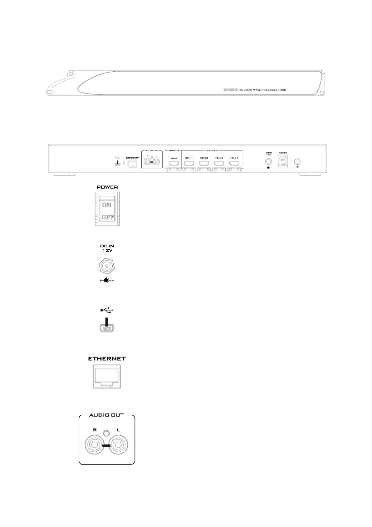
1. Power ON/OFF Switch
2. DC Power Jack
3. USB Virtual COM Port
4. Ethernet Control Port
5. Stereo Audio Output L/R
Front Panel
Lightly touch the power button on the front panel of the device to turn ON the TWP-10.
Rear Panel
Turn this power switch ON to enter the device into
STANDBY mode.
DC in socket connects the supplied 12V PSU. The
connection can be secured by screwing the outer
fastening ring of the DC In plug to the socket.
Connect this port to the PC for access to the
device user interface.
Connect this port to the PC for access to the
device user interface.
RCA Stereo for analogue audio output.
7
Page 8

6. HDMI Input
Connect the HDMI video source to this port.
7. DIP Switch
8. HDMI Outputs
ON (UP): Operation mode
OFF (DOWN): Firmware update mode
Connect video display devices to the respective
HDMI output ports.
8
Page 9
3. How to set up the TWP-10
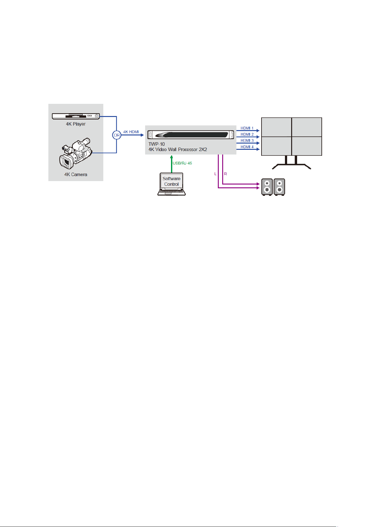
1. Set the TWP-10 as the master device.
2. Connect an HDMI video source to the HDMI input of the TWP-10.
3. Connect all display devices to the respective HDMI outputs of the TWP-10.
4. Connect the 12V 2A DC power adapter to the TWP-10.
9
Page 10
4. Software Control Program
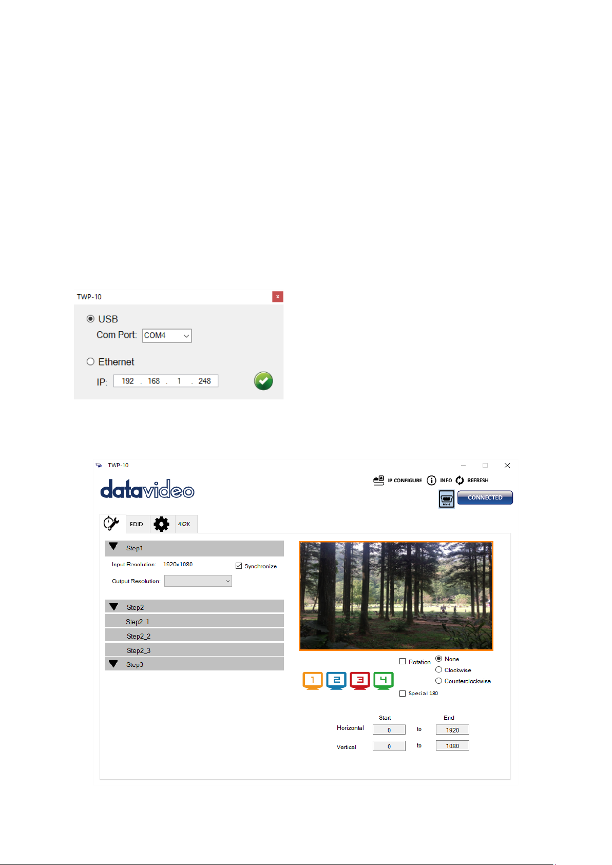
• USB: Select the appropriate virtual COM
The TWP-10 comes with a software control program which runs under Microsoft Windows
98, 2000, XP, 7, 8. Simply click the program icon after it is installed on your operating
system. However, before you start your software control program, please make sure you
have secured the connection between the PC and the TWP-10. The sections below will take
you through the system connection setup step by step.
Note: Under Microsoft Windows 7, please run as an administrator.
4.1 Start the Software Control Program
The following dialog window will pop up upon execution of the software control program.
There are basically two ways to connect the TWP-10. You can either connect via the USB
virtual COM port or the Ethernet port.
port and click the OK button.
• Ethernet: Enter the TWP-10 device IP
address and click the OK button.
After the software control program is loaded, you will see the control interface as shown
below.
10
Page 11
4.2 Program Interface
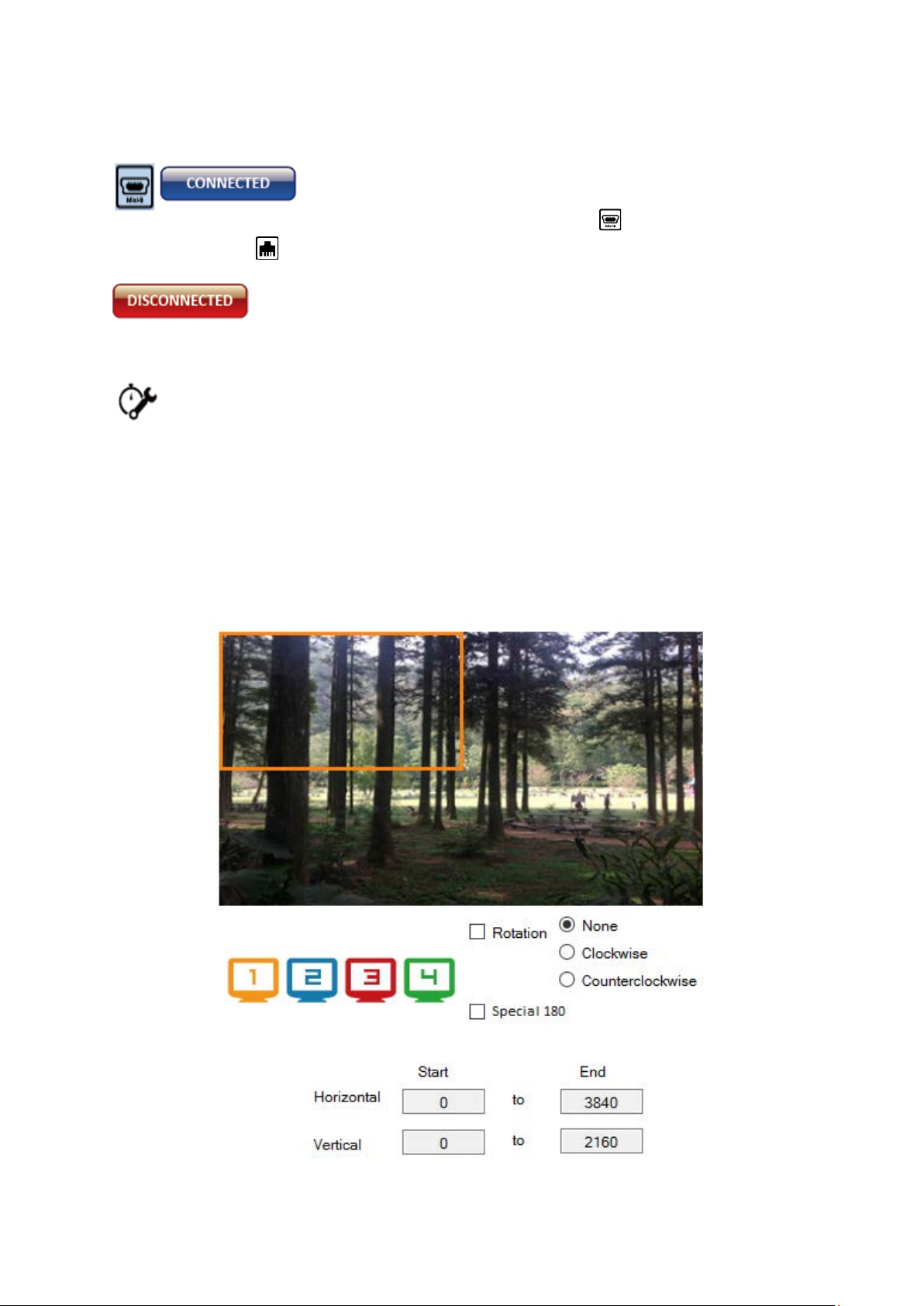
I. Connection Status
The connection status is displayed at the top right corner of the
program interface. If the PC is connected to the TWP-10 through
USB port, the icon displayed will be
Ethernet port icon , it indicates that the system setup is in IP control mode.
If connection is unsuccessful, you will see the status as DISCONNECTED.
II. Quick Setting Selection
Note: Quick Setting Selection is not available when the input resolution is
4K2K@60Hz.
On this page, you will be able to set up the screen resolution, screen coordinates and split
screen.
First of all, select the TV icon to configure the corresponding screen settings. The output TV
screens are represented by different frame colors and the coordinates displayed below are
the output TV screen position coordinates.
. However if you see an
11
Page 12
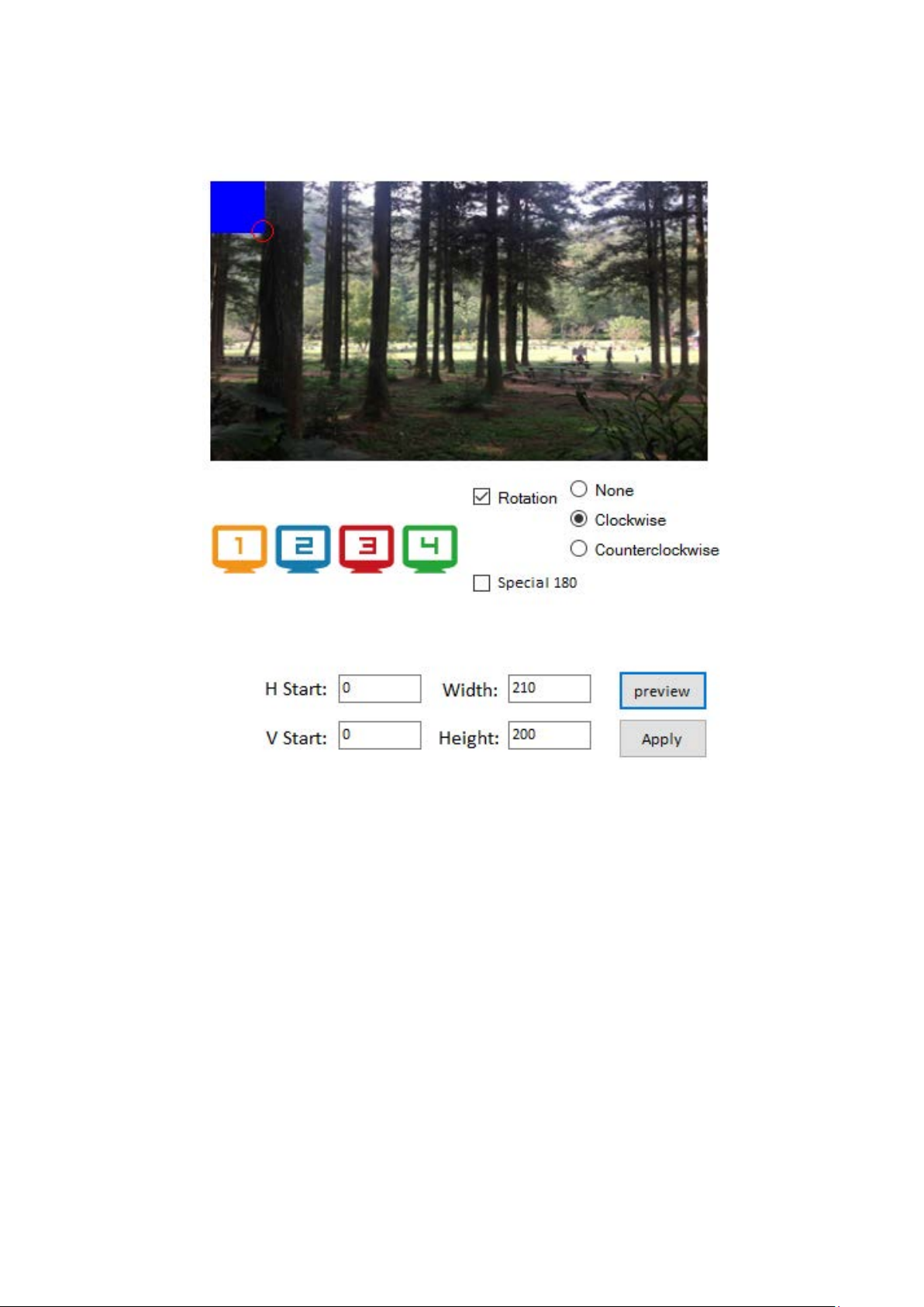
Rotation (Only available when the input is 1080p)
Use the control program to rotate the input independently. You can either rotate the screen
clockwise or anti-clockwise.
Output Selection and Resolution
Step 1: Check your input resolution and select the appropriate output resolution.
Click the TV icon to start configuring the output resolution. As you select different output
resolutions, the output TV screen position coordinates will change as well.
Note: By checking the “Synchronized” checkbox, all output TV screens must be configured
to the same resolution or the video output will be displayed incorrectly.
12
Page 13
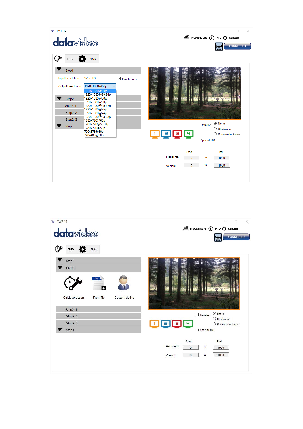
Step 2: Output Setting
At Step 2, there are three modes available for configuring the output TV resolution, position,
size and split screen. The three modes are Quick Selection, From file and Custom Settings.
The details of each mode will be described in Steps 2-1, 2-2 and 2-3 sections.
Note: Switching between different modes must only be done at Step 2.
13
Page 14
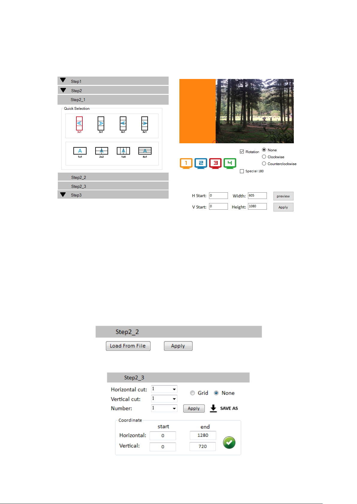
Step 2_1: Quick Selection
Various screen splits and rotations will be displayed on the control interface as soon as the
Quick Selection mode is clicked at Step 2. In this mode, you can select the desired screen
split and rotation (screen rotation is available only at 720p or 1080p).
3x1: This mode divides the screen into 3 parts and allows screen rotation.
4x1: This mode divides the screen into 4 parts and allows screen rotation.
When 3x1 or 4x1 mode is selected, a red circle will appear on the image displayed in the
right half of the control interface. You can drag this red circle to resize the output screen.
The coordinates can be adjusted by entering numbers in the respective text boxes.
Note: 4k2k60 (YUV 4:4:4) image can only be displayed as a 2x2 layout (1080p60 for each
output).
Step 2_2: Configuration from file
You can also load and read configuration file from your PC/laptop.
Step 2_3: Custom Settings
14
Page 15
In the Custom Settings mode, you can define the area that you want to display on the
output TV by cropping the image horizontally and vertically. If you want a better picture of
the selected area, please
selec
t the Grid option to display grids on the image.
After all settings are determined, please click the
button saves the configuration file on your PC for future
button to save the settings. The
use. You can also adjust
the output TV screen position by entering the horizontal and vertical coordinates.
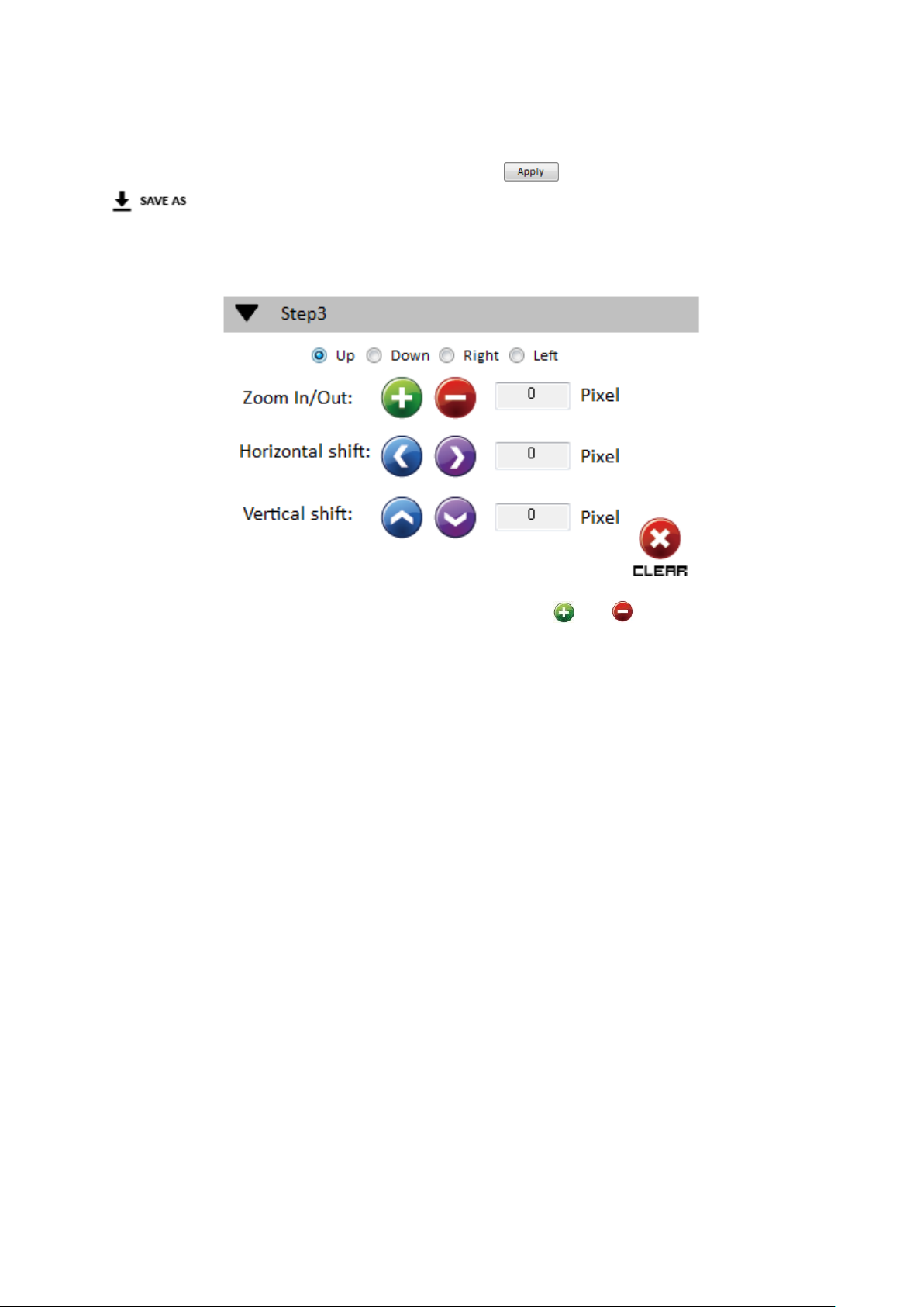
Step 3: Bezel Correction
Zoom In/Out: You can adjust the image edge by clicking and buttons to change the
pixel number (there are four image edge directions). After all image edges are adjusted, the
rest of the
image will be auto-scaled to fill the screen.
Horizontal shift/ Vertical shift: You can arbitrarily move the image on the screen in
horizontal or vertical direction. The image is moved one pixel at a time.
III. EDID (Extended Display Identification Data)
The EDID learning function is only used when you experience any display on the HDMI
output port that fails to play audio and video correctly. Because the HDMI source and display
may have different levels of capability in playing audio and video, the general rule of thumb is
that the HDMI source will output the lowest video standard in terms of the audio format and
video resolution. This allows the video output to be commonly acceptable by all HDMI
displays. In our case, the 720p stereo HDMI output signal would probably be the best choice.
However, the user can still force the device to learn the EDID of the least capable HDMI
display from all displays and make sure all displays are capable of playing the HDMI video
correctly.
15
Page 16
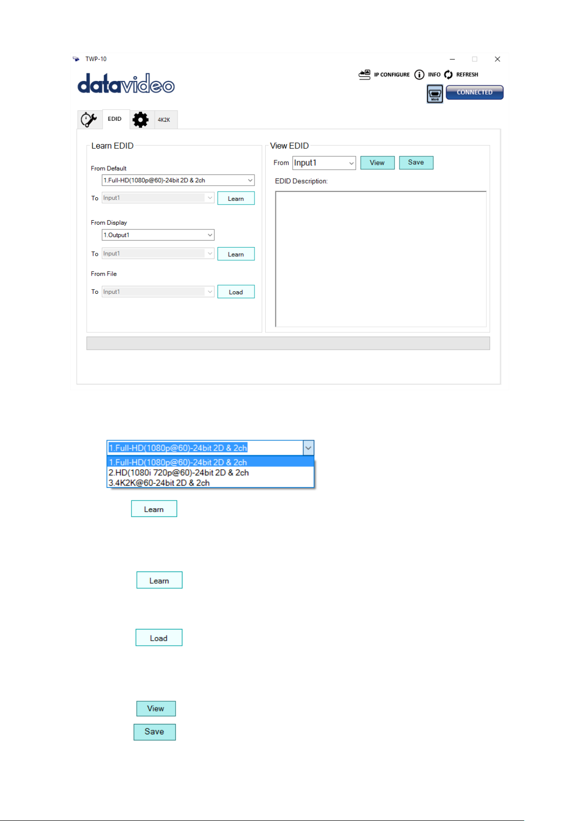
Learn EDID from Default
Select Default EDID (1-3 default EDID).
Click button to learn default EDID.
Learn EDID from Display
Select the Output.
Click button to learn display EDID.
Load EDID from File
Click button to select the EDID file and load it into the designated input.
View EDID content
Select the EDID input source (Input, Output or From File).
Click button to read the EDID description.
Click button to save the EDID as a file on the connected computer.
16
Page 17
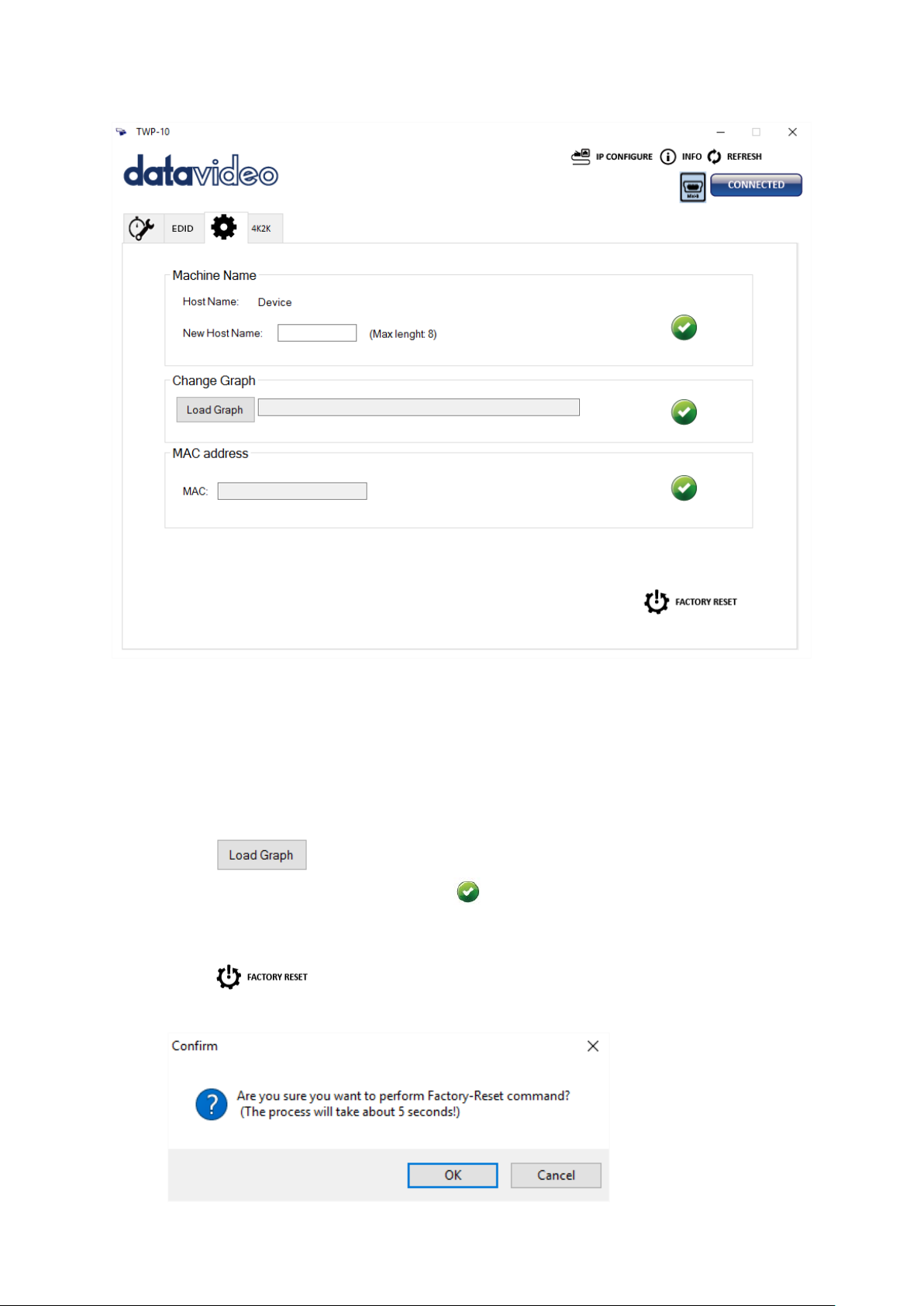
IV. Advanced Setting
Machine Name
You can give your machine a name by entering a string of characters in the “New Host
Name” textbox. Please note the maximum string length is 8.
Change Graph
You can change the default graph on this machine.
Click button to select the graph.
After the graph is loaded, please click button to write this graph into device.
Factory Reset
Click button to reset to factory default settings.
The factory reset process will take about 5 seconds.
17
Page 18
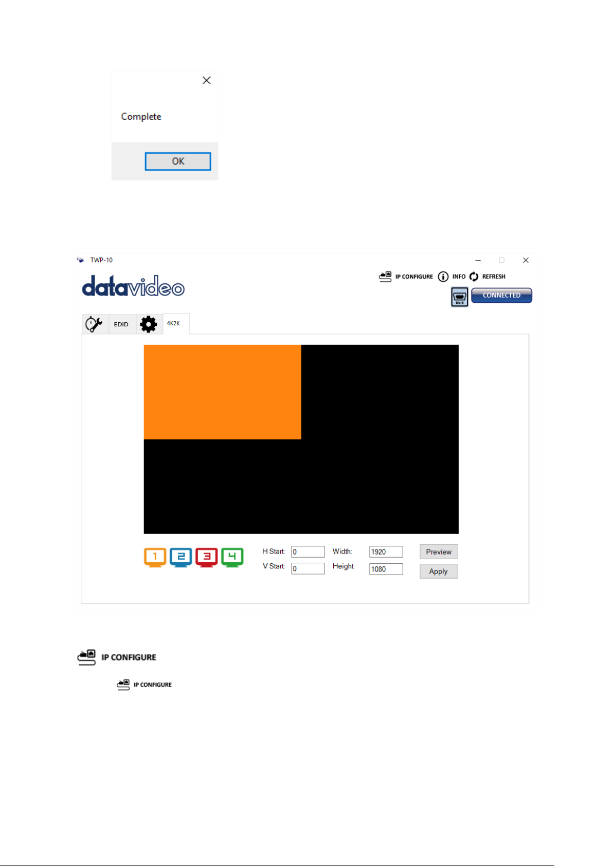
Please restart the device after the “Complete” dialog box is popped up.
V. 4K Setting
When the input resolution is 4K2K@60Hz, the output display will be forced to a 2x2 layout
(other layouts cannot be used) and only the output TV screen position is configurable.
VI. IP Configure
You can also configure the device via Ethernet connection.
1. Click
2. Next, you can read the network settings from the device
button to start configuring the network settings.
or manually write IP address to
the device.
3. By checking the DHCP box, the device will be allowed to obtain the IP address
automatically.
4. Please restart the device after the network settings are configured.
18
Page 19
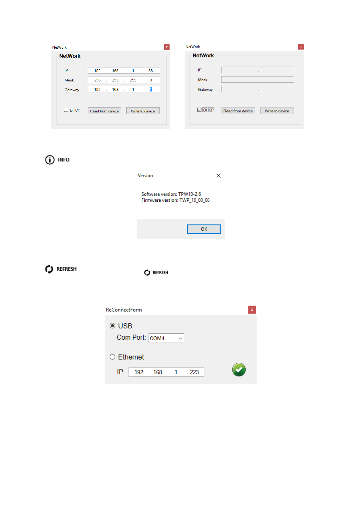
VII. Info
Clicking the Info button allows you to read the software and firmware versions.
VIII. Refresh
This function not only refreshes the setting information but also reconnects
the TWP-10. Click
button to update the connection mode. The
“ReConnectForm” dialog window will be popped
connection to the TWP-10 device.
up to allow you to re-select the mode of
19
Page 20

5. Firmware Update
Datavideo usually releases new firmware containing new features or reported bug fixes
from time to time. Customers can either download the TWP-10 firmware as they wish or
contact their local dealer or reseller for assistance.
This section outlines the firmware upgrade process which should take approximately 10
minutes to complete.
The existing TWP-10 settings should persist through the firmware upgrade process, which
should not be interrupted once started as this could result in a non-responsive unit.
Successful firmware upgrade on TWP-10 requires:
• USB drive with LED indicator
• Mini-USB to Female Type A USB cable
• Latest firmware file
Procedure
• Turn OFF the machine power (turn off the switch on the rear panel or unplug the
power cable)
• Move the DIP switch to OFF position (down)
• Connect a USB drive with at least an LED indicator to the mini-USB port of the TWP-
10 via the mini-USB to Female Type A USB cable (the USB drive should contain the
firmware file)
• Connect the power
• The firmware update is finished as soon as the USB drive indicator turns OFF
(approximately 20-30 seconds)
• Disconnect the power
• Unplug the mini-USB to Female Type A USB cable and move the DIP switch to ON
position (UP)
• Turn ON the machine again to check the firmware version.
20
Page 21
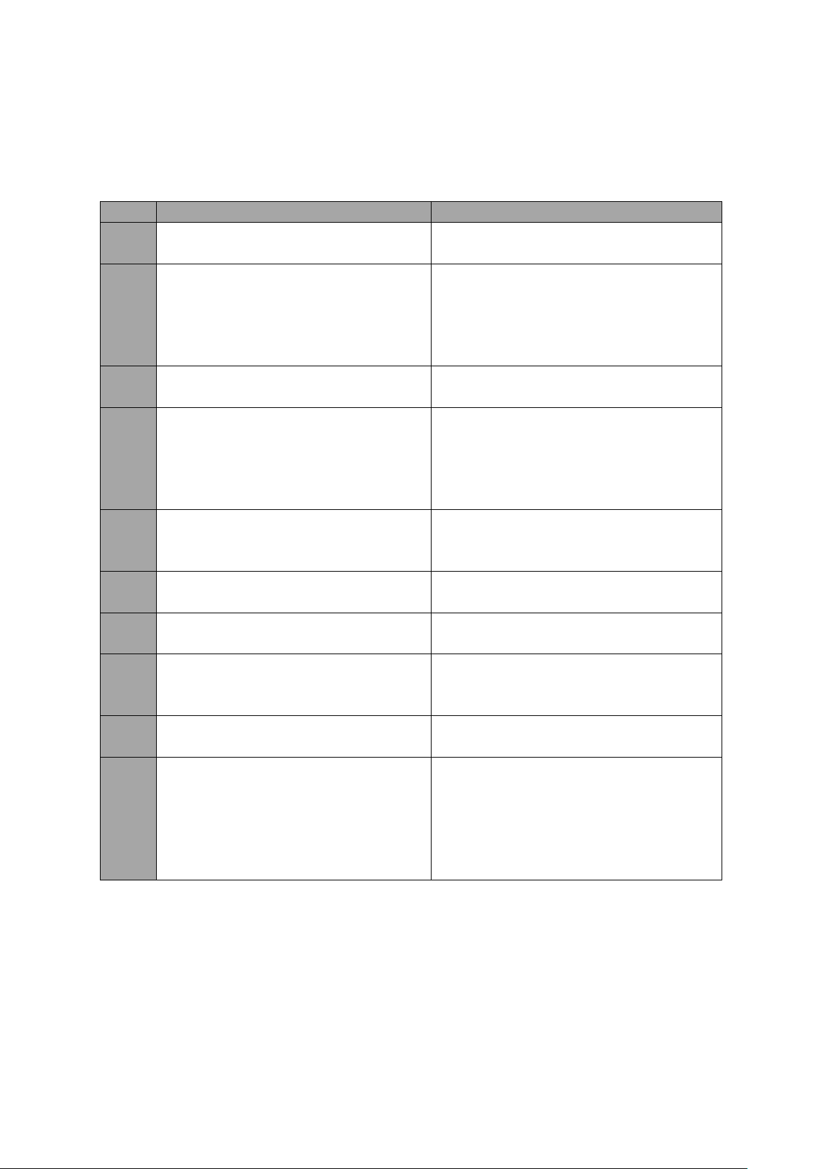
6. Frequently-Asked Questions
No.
Problems
Solutions
1.
Cannot enlarge the window in 4K 2K
mode.
In 4K 2K mode, the window can only be
shrunk.
2.
Output image is deformed.
1. At Step 2_1 Quick Selection, the
when set to rectangle mode.
3.
Video display is lost after changing the
video source.
The device must be restarted after the
video source is changed.
4.
UI displays an error message.
On the opened UI, shut down the TWP-
required to store system functions).
5.
Flicker noise is seen on the output
adjusted.
Please power cycle the device to
6.
What is the maximum audio spec on
the RCA Audio Out?
The maximum audio spec is headphone.
7.
APPLY button is not seen when using
the rotation function.
You will see the APPLY button only after
the OUTPUT CHANNEL is selected.
8.
Signal is not detected after the
After switching sources, video signal
clicking the REFRESH button.
9.
When using the rotation function, the
output image is cropped.
Please do not use the fine tune function
as this can cause problems.
10.
Jitters are seen on the output image.
When the input resolution is 1920x1080i
input source.
This section describes problems that you may encounter while using TWP-10. If you have
any questions, please refer to related sections and follow all suggested solutions. If problem
still exists, please contact your distributor or the service center.
output image will be deformed
when 1x4 or 4x1 is selected.
2. In UI, the output image is deformed
10 and power it ON again, an error
message will be displayed on the
opened UI (device power cycle is
image after the output resolution is
REFRESH button is clicked.
eliminate this issue.
sometimes cannot be detected after
50/59.94/60, all output resolutions will
create jitters on the output image. This
is the hardware limitation so it is
recommended not to use 1080i as the
21
Page 22
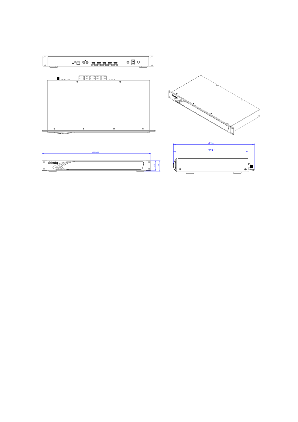
7. Dimensions & Weight
All measurements in millimeters (mm)
22
Page 23
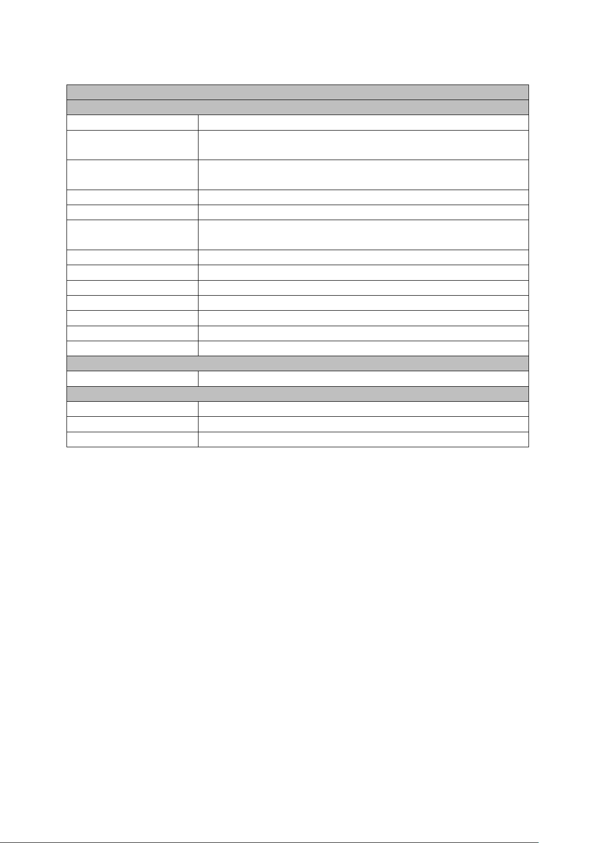
8. Specifications
Video Wall Processor
Interfaces
HDCP Compliance
Yes
Video Bandwidth
Input – Single Link 600 MHz [18 Gbps]
Output – Single Link 225 MHz [6.75 Gbps]
Video Resolution
Input – 4K2K@60 (4:2:0 10 bits) / 4K2K@60 (4:4:4 8 bits)
Output – 1920X1080@60 / 1920x1200@60
Video Format
HDMI
Audio Support
Yes
ESD Protection
Human body - ±15kV [Air-gap discharge] & ±8kV [Contact
discharge]
Input Port
1xHDMI / 1xUSB / 1xRJ-45
Output Port
4xHDMI / 1xStereo
Control
IR Remote Control / Ethernet / USB (Virtual) / Front Panel
Input TMDS Signal
1.2 Volts [peak-to-peak]
HDMI Connector
Type A [19 PIN Female]
Mini-USB Connector
Type A
RJ-45 Connector
WE/SS 8P8C
Electrical
Power Supply
12V 2A DC
Others
Operating Temperature
0 – 40°C [32 – 104°F]
Storage Temperature
-20 – 60°C [-4 – 140°F]
Operating Humidity
20 – 90% RH [No Condensation]
23
Page 24
DATAVIDEO WORLDWIDE OFFICES
Service & Support
It is our goal to make owning and using Datavideo products a satisfying experience. Our support sta is available
to assist you to set up and operate your system. Contact your local office for specific support requests. Plus,
please visit www.datavideo.com to access our FAQ section.
China Shanghai
Datavideo Technologies China Co
601,Building 10,No.1228,
Rd.Jiangchang,
Jingan District,Shanghai
Tel: +86 21-5603 6599
Fax:+ 86 21-5603 6770
E-mail: [email protected]
China Beijing
Datavideo Technologies China Co
No. 812, Building B, Wankai Center,
No.316, Wan Feng Road, Fengtai District,
Beijing, China
Tel: +86 10-8586 9034
Fax:+86 10-8586 9074
E-mail: [email protected]
China Chengdu
Datavideo Technologies China Co
B-823,Meinian square,No.1388,
Middle of Tianfu Avenue,Gaoxin District,
Chengdu,Sichuan
Tel: +86 28-8613 7786
Fax:+86 28-8513 6486
E-mail: [email protected]
China Fuzhou
Datavideo Technologies China Co
A1-2318-19 Room,No.8, Aojiang Road,
Taijiang District,Fuzhou,Fujian,China
Tel: 0591-83211756,0591-83210187
Fax:0591-83211262
E-mail: [email protected]
China Jinan
Datavideo Technologies China Co
902, No. 1 business building,
Xiangtai Square, No. 129,
Yingxiongshan Road, Shizhong District,
Jinan City, Shandong Province, China
Tel: +86 531-8607 8813
E-mail: [email protected]
Hong Kong
Datavideo Hong K ong Ltd
G/ F.,26 Cross Lane
Wanchai, Hong Kong
Tel: +852-2833-1981
Fax:+ 852-2833-9916
E-mail: [email protected]
India Noida
Datavideo India Noida
A-132, Sec-63,Noida-201307,
India
Tel: +91-0120-2427337
Fax:+91-0120-2427338
E-mail: [email protected]
India Kochi
Datavideo India Kochi
2nd Floor- North Wing, Govardhan Building,
Opp. NCC Group Headquaters, Chittoor Road,
Cochin- 682035
Tel: +91 4844-025336
Fax:+91 4844-047696
Netherlands
Data video Technologies Europe BV
Floridadreef 106
3565 AM Ut recht ,
Th e Netherlands
Tel: +31-30-261-9 6-56
Fa x:+ 31-30-261-96-57
E-mail: info@data video.n l
Singapore
Datavideo Visual Technology(S) Pte Ltd
No. 178 Paya Lebar Road #06-07
Singapore 409030
Tel: +65-6749 6866
Fa x:+65-6749 3266
E-mail:[email protected]
Singapore
Data video Technologies (S) PTE L td
No. 178 Paya Lebar Road #06-03
Singapore 409030
Tel: +65-6749 6866
Fa x:+65-6749 3266
E-mail:s ales@data video.sg
Taiwan
Datavideo Technologies Co. Lt d
10F. No. 176, Jian 1st Rd.,Chung Ho
District, New Taipei City 235, Taiwan
Tel: +886-2-8227-2888
Fax:+886-2-8227-2777
E-mail:service@dat avideo.com.tw
United States
Datavideo Corporat ion
7048 Elmer Avenue.
Whittier, C A 90602,
U.S.A.
Tel: +1-562-696 2324
Fax:+1-562-698 6930
E-mail:[email protected]E-mail: [email protected]
United Kingdom
Data video UK Lim ite d
Brookfield House, Brookfield Industrial
Estate, Peakdale Road, Glossop,
Derbyshire, SK13 6LQ
Tel: +44-1457 851 000
Fa x:+ 44-1457 850 964
E-mail: [email protected] .uk
France
Datavideo France s.a.r.l.
Cité Descartes 1, rue Albert Einstein
Champs sur Marne 774477 –
Marne la Vallée cedex 2
Tel: +33-1-60370246
Fa x:+33-1-60376732
E-mail: [email protected]
Please visit our website for latest manual update.
www.datavideo.com/product/TWP-10
All the trademarks are the properties of their respective owners. Datavideo Technologies Co., Ltd. All rights reserved 2018
Jul-17.2017
 Loading...