

Page 1
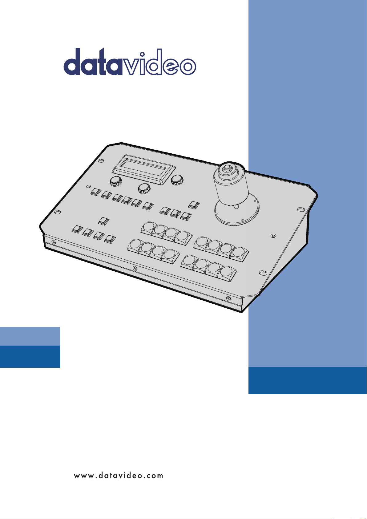
KMU CONTROLLER
RMC-185
Instruction manual
Page 2

Table of Contents
FCC COMPLIANCE STATEMENT .................................................................................................................................... 3
WARNINGS AND PRECAUTIONS .................................................................................................................................. 3
WARRANTY ................................................................................................................................................................. 4
STANDARD WARRANTY ......................................................................................................................................................... 4
THREE YEAR WARRANTY ....................................................................................................................................................... 4
DISPOSAL .................................................................................................................................................................... 4
1. INTRODUCTION....................................................................................................................................................... 5
1.1 FEATURES ............................................................................................................................................................... 5
1.2 DEVICE SETUP ......................................................................................................................................................... 5
2. CONNECTIONS AND CONTROLS .............................................................................................................................. 6
2.1 FRONT PANEL – KEYBOARD ........................................................................................................................................ 6
2.2 REAR PANEL - CONNECTIONS ...................................................................................................................................... 8
3. MENU SETUP .......................................................................................................................................................... 9
FN1. EXITS THE MENU (EXIT) ............................................................................................................................................ 10
FN2. INPUT A SOURCE ASSIGNMENT (INPUT A SOURCE) .......................................................................................................... 10
FN3. INPUT B SOURCE ASSIGNMENT (INPUT B SOURCE) ........................................................................................................... 10
FN4. OUTPUT FORM AT SELECTION (OUTPUT FORMAT) ............................................................................................................ 10
FN5. GENLOCK SETTING (GENLOCK SET) ................................................................................................................................ 11
FN6. GENLOCK STATU S DI S P L AY (GENLOCK STATUS) ................................................................................................................. 11
FN7. SELECTION OF SDI 3G TYPE (SDI 3G TYPE) .................................................................................................................... 11
FN8. HDMI MULTIVIEWER SWAP (MULTI. SWAP) .................................................................................................................. 11
FN9. SDI 4 MULTIVIEWER (MULT I. SDI) ............................................................................................................................... 11
FN10. EXTERNAL MOTION TRIGGER SETTING (TRIGGER SET) ..................................................................................................... 11
FN11. KMU-100 FIRMWARE VERSION DISPL AY (KMU-100 VER.) ........................................................................................... 11
FN12. DISPLAY OF KMU-100 FPGA AND PCB BOARD TEMPERATURES (KMU-100 TEMP) ........................................................... 11
FN13. RMC-185 FIRMWARE VERSION DI S P L AY (FIRMWARE VER.) ............................................................................................ 11
4. STORING DIFFERENT DEVICE SETTINGS ..................................................................................................................12
5. FIRMWARE UPGRADE PROCEDURE ........................................................................................................................13
6. FREQUENTLY-ASKED QUESTIONS ............................................................................................................................16
7. DIMENSIONS ..........................................................................................................................................................17
8. SPECIFICATIONS .....................................................................................................................................................17
SERVICE AND SUPPORT..............................................................................................................................................18
Disclaimer of Product and Services
The information offered in this instruction manual is intended as a guide only. At all times, Datavideo Technologies will
try to give correct, complete and suitable information. However, Datavideo Technologies cannot exclude that some
information in this manual, from time to time, may not be correct or may be incomplete. This manual may contain
typing errors, omissions or incorrect information. Datavideo Technologies always recommend that you double check
the information in this document for accuracy before making any purchase decision or using the product. Datavideo
Technologies is not responsible for any omissions or errors, or for any subsequent loss or damage caused by using the
information contained within this manual. Further advice on the content of this manual or on the product can be
obtained by contacting your local Datavideo Office or dealer.
2
Page 3

FCC Compliance Statement
This device complies with part 15 of the FCC rules. Operation is subject to the following two conditions:
1. This device may not cause harmful interference, and
2. This device must accept any interference received, including interference that may cause undesired
operation.
Warnings and Precautions
1. Read all of these warnings and save them for later reference.
2. Follow all warnings and instructions marked on this unit.
3. Unplug this unit from the wall outlet before cleaning. Do not use liquid or aerosol cleaners. Use a damp
cloth for cleaning.
4. Do not use this unit in or near water.
5. Do not place this unit on an unstable cart, stand, or table. The unit may fall, causing serious damage.
6. Slots and openings on the cabinet top, back, and bottom are provided for ventilation. To ensure safe
and reliable operation of this unit, and to protect it from overheating, do not block or cover these
openings. Do not place this unit on a bed, sofa, rug, or similar surface, as the ventilation openings on
the bottom of the cabinet will be blocked. This unit should never be placed near or over a heat register
or radiator. This unit should not be placed in a built-in installation unless proper ventilation is provided.
7. This product should only be operated from the type of power source indicated on the marking label of
the AC adapter. If you are not sure of the type of power available, consult your Datavideo dealer or your
local power company.
8. Do not allow anything to rest on the power cord. Do not locate this unit where the power cord will be
walked on, rolled over, or otherwise stressed.
9. If an extension cord must be used with this unit, make sure that the total of the ampere ratings on the
products plugged into the extension cord do not exceed the extension cord rating.
10. Make sure that the total amperes of all the units that are plugged into a single wall outlet do not exceed
15 amperes.
11. Never push objects of any kind into this unit through the cabinet ventilation slots, as they may touch
dangerous voltage points or short out parts that could result in risk of fire or electric shock. Never spill
liquid of any kind onto or into this unit.
12. Except as specifically explained elsewhere in this manual, do not attempt to service this product
yourself. Opening or removing covers that are marked “Do Not Remove” may expose you to dangerous
voltage points or other risks, and will void your warranty. Refer all service issues to qualified service
personnel.
13. Unplug this product from the wall outlet and refer to qualified service personnel under the following
conditions:
a. When the power cord is damaged or frayed;
b. When liquid has spilled into the unit;
c. When the product has been exposed to rain or water;
d. When the product does not operate normally under normal operating conditions. Adjust only those
controls that are covered by the operating instructions in this manual; improper adjustment of
other controls may result in damage to the unit and may often require extensive work by a qualified
technician to restore the unit to normal operation;
e. When the product has been dropped or the cabinet has been damaged;
f. When the product exhibits a distinct change in performance, indicating a need for service.
3
Page 4

Warranty
Standard Warranty
• Datavideo equipment are guaranteed against any manufacturing defects for one year from the date
of purchase.
• The original purchase invoice or other documentary evidence should be supplied at the time of any
request for repair under warranty.
• The product warranty period beings on the purchase date. If the purchase date is unknown, the
product warranty period begins on the thirtieth day after shipment from a Datavideo office.
• Damage caused by accident, misuse, unauthorized repairs, sand, grit or water is not covered under
warranty.
• Viruses and malware infections on the computer systems are not covered under warranty.
• Any errors that are caused by unauthorized third-party software installations, which are not
required by our computer systems, are not covered under warranty.
• All mail or transportation costs including insurance are at the expense of the owner.
• All other claims of any nature are not covered.
• Cables and batteries are not covered under warranty.
• Warranty only valid in the country or region of purchase.
• Your statutory rights are not affected.
Three Year Warranty
• All Datavideo products purchased after July 1st, 2017 are qualified for a free two years extension to
the standard warranty, providing the product is registered with Datavideo within 30 days of
purchase.
• Certain parts with limited lifetime expectancy such as LCD panels, DVD drives, Hard Drive, Solid
State Drive, SD Card, USB Thumb Drive, Lighting, Camera module, PCIe Card are covered for 1 year.
• The three-year warranty must be registered on Datavideo's official website or with your local
Datavideo office or one of its authorized distributors within 30 days of purchase.
Disposal
For EU Customers only - WEEE Marking
This symbol on the product or on its packaging indicates that this product must not be
disposed of with your other household waste. Instead, it is your responsibility to
dispose of your waste equipment by handing it over to a designated collection point for
the recycling of waste electrical and electronic equipment. The separate collection and
recycling of your waste equipment at the time of disposal will help to conserve natural
resources and ensure that it is recycled in a manner that protects human health and the
environment. For more information about where you can drop off your waste
equipment for recycling, please contact your local city office, your household waste disposal service or the
shop where you purchased the product.
CE Marking is the symbol as shown on the left of this page. The letters "CE" are the
abbreviation of French phrase "Conformité Européene" which literally means "European
Conformity". The term initially used was "EC Mark" and it was officially replaced by "CE
Marking" in the Directive 93/68/EEC in 1993. "CE Marking" is now used in all EU official
documents.
4
Page 5
1. Introduction
The RMC-185 is a cost effective physical controller designed specifically for control of the KMU-100
4K Multi-Camera Processor. The RMC-185 interfaces with the KMU-100 via an RS-422 interface.
The RMC-185 panel style design allows easy control of the KMU-100 with the hard keys giving the
user quick access to main functions of the KMU-100. In addition, you can also use the joystick to
move the selected frame view.
That’s Datavideo; sharing the value!
1.1 Features
• Remote control of up to eight selected frame views.
• Pan, Tilt and Zoom with speed control by joystick.
• Storing multiple presets for frame view settings.
• Full remote control of the KMU-100 via RS-422 connection.
• An LCD display showing setup menu options.
• Three Multiviewer modes (Preview, Motion and Quad)
• Compact design for easy installation
1.2 Device Setup
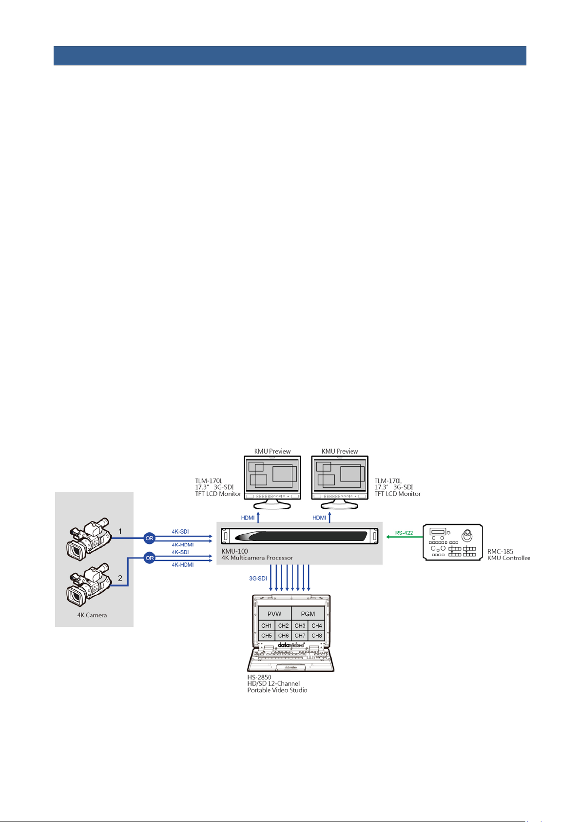
The RMC-185 works in pair with the KMU-100. First of all, connect the power to the RMC-185
through a power cable. After that, the RMC-185 (RJ-45) is connected to the KMU-100 (DSub) using
an RJ-45-to-DSub cable. Finally, turn ON the RMC-185 device switch to start manipulating your
KMU-100. Please see the system diagram below for the overall system setup.
Note: The communication protocol between the two devices is RS-422.
5
Page 6
2. Connections and Controls
configuration menu can be
2.1 Front Panel – Keyboard
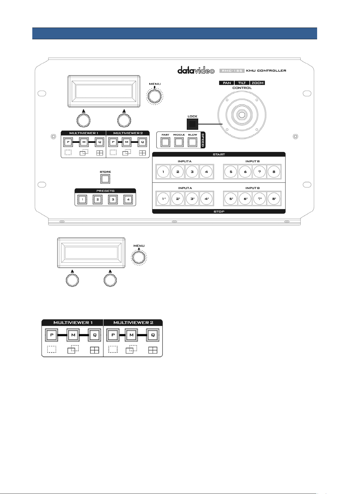
LCD Display
The RMC-185 status or the setup menu options
are displayed on the LCD panel.
Menu Control Dials
The RMC-185
entered and browsed using these dials. Push to
select a specific item and rotate to browse the
selected menu option.
Multiviewer Mode Select
P Preview
Press to display current position of the
selected frame.
M Motion
Press to display motion of the selected
frame (playback of the motion from
Start position to End position).
Q Quad View
Simultaneous display of all four frames.
6
Page 7
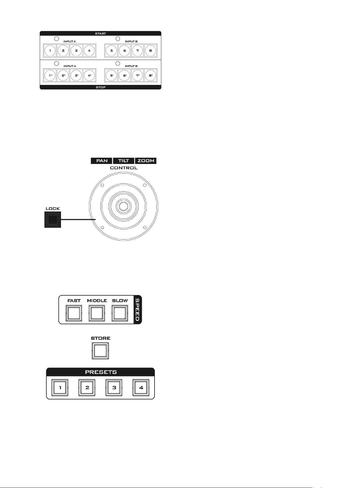
Frame selection buttons (Top row)
the same button for
Twist the joystick clockwise (to the
selected frame zoom in or out.
state. To resume its functional status, simply
press the button once to unlock the joystick.
185 into
ssing the corresponding
. Simply press the
activated, the button LED will be turned ON.
Press one button (1-8) to select an active frame.
After selecting an active frame, you can press
the same button to switch between Start and
End positions.
Motion operation buttons (Bottom row)
Press one button to start motion of an active
frame and the second button press pauses
motion. Long pressing
about 2 seconds will stop motion. Button LED
flashes while the motion is in progress. When
the motion is stopped, the button LED will stop
flashing and turn to constant lit.
PTZ Joystick Control
Note: Before attempting to use the joystick to
PAN, TILT or ZOOM a selected frame, first make
sure the LOCK button is not enabled.
PAN – Move the joystick left or right to pan the
selected frame from left to right or vice versa.
TILT – Move the joystick up or down to tilt the
selected frame up or down.
ZOOM –
right) or anti-clockwise (to the left) to have the
LOCK Button
When enabled, the joystick will be in the lock
Speed
The speed at which the selected frame moves
can be chosen by pressing one of the three
speed buttons.
STORE
Pressing this button enters the RMCSTORE MODE. When activated, this allows the
current device setting to be stored in a chosen
Preset Button by pre
Preset Button. Press again to exit STORE MODE.
PRESETS
The preset buttons may be used to store up to
four device settings. Each button corresponds to
one stored device preset
button to recall the saved preset. Once
7
Page 8
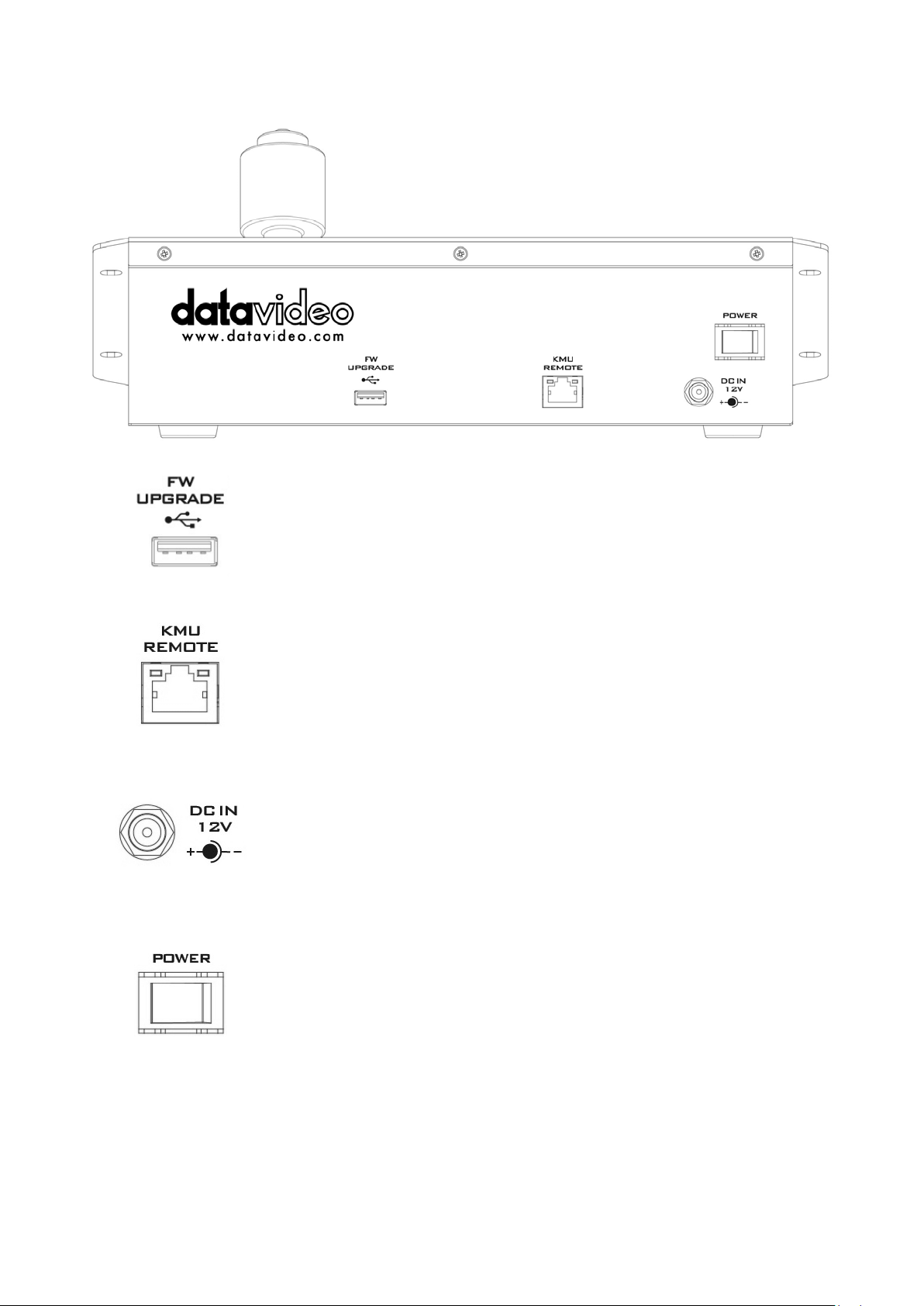
2.2 Rear Panel - Connections
for connection to a computer during the firmware
Firmware Upgrade
USB type A port
upgrade process.
RJ-45 port to connect the KMU-100
The RJ-45 ports are provided on the RMC-185 rear to connect the KMU-
100. The communication protocol is RS-422, so use an RJ-45-to-DSub
cable to connect the RMC-185 to the RS-422 port located on the KMU100 rear panel.
DC In Socket
Connect the supplied 12V 0.5A PSU to this socket. The connection can
be secured by screwing the outer fastening ring of the DC In plug to the
socket.
Power On/Off Switch
Switches the device ON / OFF.
8
Page 9
1 x SDI
Clone
1 x SDI
Clone
PAL
1080p60
Enable
Disable
Enable
Disable
Present
Loose
Lock
Unlock
Detected video format
Up to 1080p60
Type A
Type B
FN1 Exit
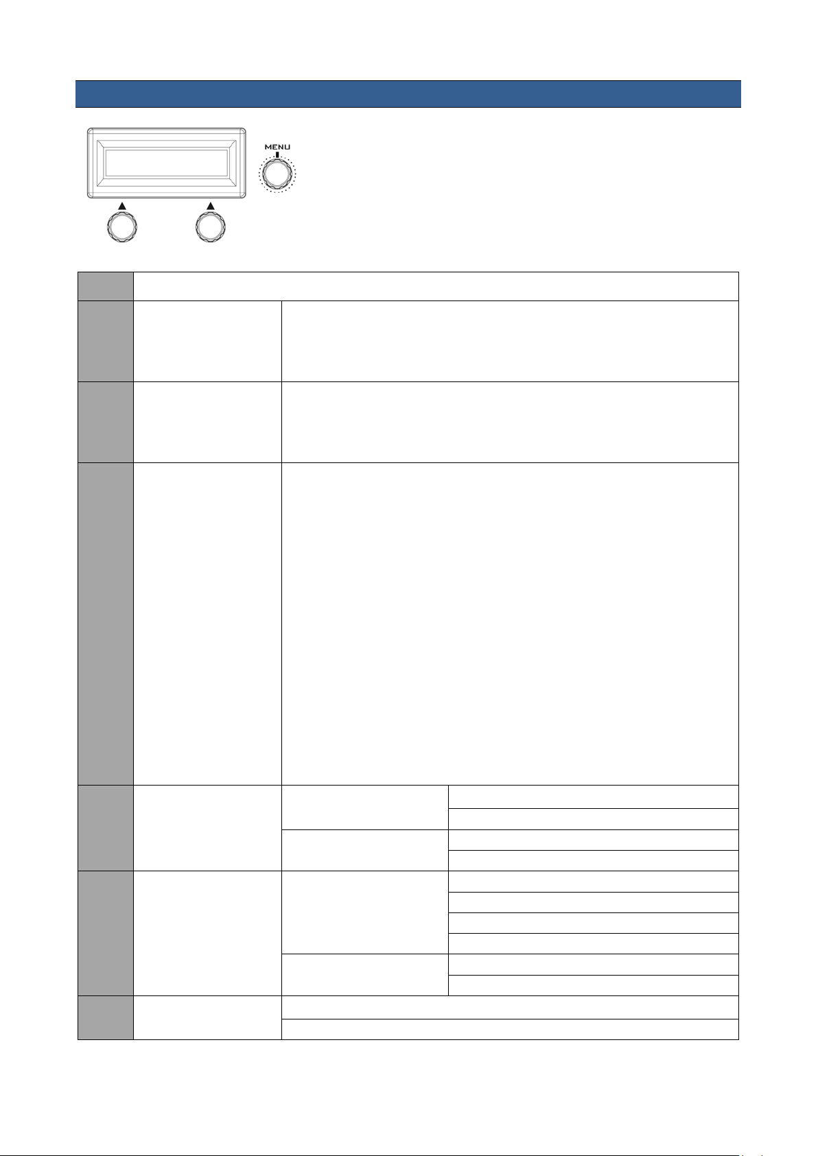
3. Menu Setup
Press the MENU button to enter the MENU. The RMC-185
status or the setup menu options are displayed on the LCD
panel.
Press the dial to select a particular option and rotate the dial
to browse through the option items.
FN2 Input A Source
FN3 Input B Source
FN4 Output Format
4 x SDI
HDMI
4 x SDI
HDMI
NTSC
PAL 16:9
NTSC 16:9
720p50
720p59.94
720p60
1080p25
1080p29.97
1080p30
1080i50
1080i59.94
1080i60
1080p50
1080p59.94
FN5 Genlock Set
FN6 Genlock Status
FN7 SDI 3G Type
Genlock
Termination
Ref
Format
9
Page 10

FN8 Multi. Swap
ON
OFF
ON
OFF
Low
FPGA Temperature
PCB Board Temperature
FN13
Firmware Ver.
RMC-185 Firmware Version
FN9 Multi. SDI
Motion No. 1 – 8
FN10 Trigger Set
FN11 KMU-100 Ver. FPGA / HARDWARE / NIOS / ARM
FN12 KMU-100 Temp
Trigger Level
High
FN1. Exits the MENU (EXIT)
Exits the setup menu mode.
FN2. Input A Source Assignment (Input A Source)
In this option, you may select a source for input A image processing. The available interfaces are:
• 1xSDI – SDI video interface up to 12G (SD is not supported)
• 4xSDI – quad SDI video
• HDMI – HDMI 2.0
• Clone – Input B as a source
FN3. Input B Source Assignment (Input B Source)
In this option, you may select a source for input B image processing. The available interfaces are:
• 1xSDI – SDI video interface up to 12G (SD is not supported)
• 4xSDI – quad SDI video
• HDMI – HDMI 2.0
• Clone – Input A as a source
FN4. Output Format Selection (Output Format)
There are many video output formats available for selection. The available video output formats
are listed as follows:
• PAL
• NTSC
• PAL 16:9
• NTSC 16:9
• 720p50
• 720p59.94
• 720p60
• 1080p25
• 1080p29.97
• 1080p30
• 1080i50
• 1080i59.94
• 1080i60
• 1080p50
10
Page 11

• 1080p59.94
• 1080p60
FN5. Genlock Setting (Genlock Set)
This option enables/disables the genlock functionality and turns ON/OFF internal 75 Ohm
termination.
FN6. Genlock Status Display (Genlock Status)
Display current genlock status by returning values detected from sync signal.
FN7. Selection of SDI 3G Type (SDI 3G Type)
Enabling of 3G-SDI signal type on output ports (available modes are Type A and Type B).
FN8. HDMI Multiviewer Swap (Multi. Swap)
If Multi. Swap is set to ON, the multiviewer contents of the KMU-100 HDMI outputs will be
swapped.
FN9. SDI 4 Multiviewer (Multi. SDI)
If Multi.SDI is set to ON, the 4th SDI output of every output channel on the KMU-100 works as a
multiviewer output.
FN10. External Motion Trigger Setting (Trigger Set)
In this option, you will be able to configure the external motion trigger method. Motion 1-8 can be
controlled by an external device using the level trigger method. You can either set the trigger
method to low level trigger or high level trigger.
FN11. KMU-100 Firmware Version Display (KMU-100 Ver.)
Upon entering the KMU-100 Ver. Option, the KMU-100 firmware version will be displayed.
FN12. Display of KMU-100 FPGA and PCB Board Temperatures (KMU-100 Temp)
In the KMU-100 Temp option, you will be able to check measured temperatures of the KMU-100
FPGA and PCB boards.
FN13. RMC-185 Firmware Version Display (Firmware Ver.)
Upon entering the Firmware Ver. option, the RMC-185 firmware version will be displayed.
11
Page 12
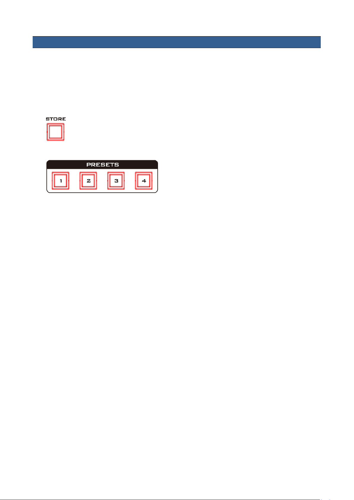
4. Storing Different Device Settings
The RMC-185 allows you to store up to four device settings. Follow the procedure below to store
the current device setting to one of the preset buttons.
To store a device setting:
1. Adjust the frame positions using the joystick.
2. Push the STORE button and it will turn red.
3. Press a preset button to save the current device setting.
4. The selected preset button will remain ON for 2-3 seconds and the button LED will be turned
OFF after the device setting is successfully saved.
12
Page 13
5. Firmware Upgrade Procedure
From time to time, Datavideo may release new firmware to either add new features or to fix
reported bugs in the current RMC-185 firmware. Customers can update the firmware themselves if
they wish or they can contact their local dealer or reseller for assistance should they prefer this
method.
This section describes the firmware update process and it should take approximately few minutes
to complete. Once started, the update process should not be interrupted in any way as this could
result in a non-responsive unit.
Requirement
• Latest firmware update files (bootloader and application firmware)
• A USB A to USB A cable not longer than 2 meters
• A Windows PC with USB 2.0 ports or above
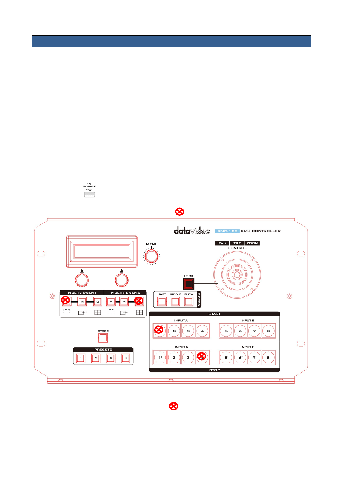
1. Power off the RMC-185 and use a USB cable (USB A to USB A) to connect the USB firmware
upgrade port on the RMC-185 rear panel to a USB port on the PC.
2. Press and hold the four buttons indicated with at the same time.
3. With an assistant’s help, one person switches on the RMC-185 device while another person
presses and holds the buttons indicated with .
4. The user may release the buttons once the RMC-185 LCD panel displays the following
information.
13
Page 14
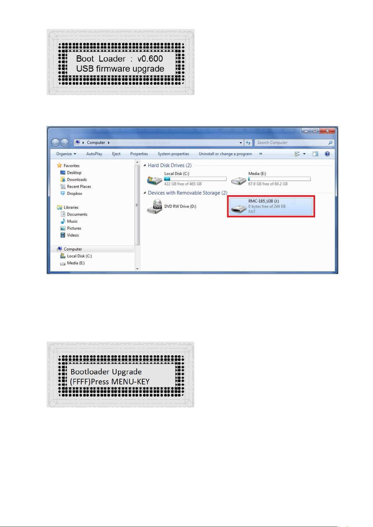
5. The RMC-185 device (RMC-185_U38) will appear as a removable storage device on the PC as
shown below.
6. Double click the RMC-185_U38 removable storage device and delete the “bootcode.bin” file.
7. Copy and paste the latest bootloader firmware file (bootcode.bin) into the RMC-185_U38
removable storage device.
8. Reboot the RMC-185 device until the LCD displays the following.
9. Press the MENU key to start the firmware upgrade and do not disconnect the power before the
upgrade is complete.
14
Page 15
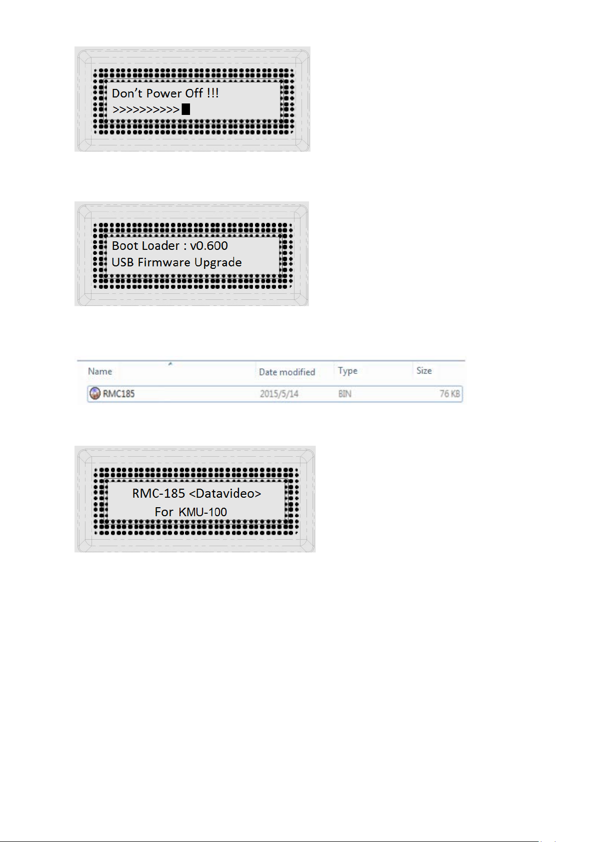
10. After the bootloader firmware upgrade is complete, the LCD display will show the following
and the user may proceed to upgrading the application firmware.
11. Remove bootcode.bin from the RMC-185 device and copy and paste the application firmware
into the RMC-185 device.
12. Reboot the RMC-185 device again and the LCD display will now show the following.
13. The RMC-185 device is now ready for controlling the connected KMU device.
15
Page 16

No.
Problems
Solutions
1.
What is the RJ-45 port used for?
It is used for connecting the RMC-185 to the
The DSub end should be a male connector.
6. Frequently-Asked Questions
This section describes problems that you may encounter while using RMC-185. If you have any
questions, please refer to related sections and follow all suggested solutions. If problem still exists,
please contact your distributor or the service center.
KMU-100. Please use an RJ-45-to-DSub cable.
16
Page 17
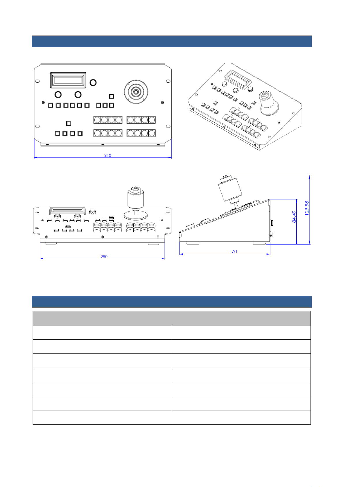
7. Dimensions
All measurements in millimeters (mm)
8. Specifications
RMC-185 KMU Controller
Firmware Upgrade USB
Power DC 12V 0.5A
Dimensions (W x H x D) 310 x 129.98 x 170 (mm)
Net Weight 1.5 Kg
Gross Weight 2.0 Kg
Operating Temperature 0°C to 50°C (32°F to 122°F)
Humidity 10% to 80%
17
Page 18
DATAVIDEO WORLDWIDE OFFICES
Service & Support
It is our goal to make owning and using Datavideo products a satisfying experience. Our support sta is available
to assist you to set up and operate your system. Contact your local office for specific support requests. Plus,
please visit www.datavideo.com to access our FAQ section.
China Shanghai
Datavideo Technologies China Co
601,Building 10,No.1228,
Rd.Jiangchang,
Jingan District,Shanghai
Tel: +86 21-5603 6599
Fax:+ 86 21-5603 6770
E-mail: [email protected]
China Beijing
Datavideo Technologies China Co
No. 812, Building B, Wankai Center,
No.316, Wan Feng Road, Fengtai District,
Beijing, China
Tel: +86 10-8586 9034
Fax:+86 10-8586 9074
E-mail: [email protected]
China Chengdu
Datavideo Technologies China Co
B-823,Meinian square,No.1388,
Middle of Tianfu Avenue,Gaoxin District,
Chengdu,Sichuan
Tel: +86 28-8613 7786
Fax:+86 28-8513 6486
E-mail: [email protected]
China Fuzhou
Datavideo Technologies China Co
A1-2318-19 Room,No.8, Aojiang Road,
Taijiang District,Fuzhou,Fujian,China
Tel: 0591-83211756,0591-83210187
Fax:0591-83211262
E-mail: [email protected]
China Jinan
Datavideo Technologies China Co
902, No. 1 business building,
Xiangtai Square, No. 129,
Yingxiongshan Road, Shizhong District,
Jinan City, Shandong Province, China
Tel: +86 531-8607 8813
E-mail: [email protected]
Hong Kong
Datavideo Hong K ong Ltd
G/ F.,26 Cross Lane
Wanchai, Hong Kong
Tel: +852-2833-1981
Fax:+ 852-2833-9916
E-mail: info@dat avideo.com.hk
India Noida
Datavideo India Noida
A-132, Sec-63,Noida-201307,
India
Tel: +91-0120-2427337
Fax:+91-0120-2427338
E-mail: [email protected]
India Kochi
Datavideo India Kochi
2nd Floor- North Wing, Govardhan Building,
Opp. NCC Group Headquaters, Chittoor Road,
Cochin- 682035
Tel: +91 4844-025336
Fax:+91 4844-047696
Netherlands
Data video Technologies Europe B V
Floridadreef 106
3565 AM Ut rech t,
Th e Netherlands
Tel: +31-30-261-9 6-56
Fa x: +31-30-261-9 6-57
E-mail: info@dat av ideo.n l
Singapore
Datavideo Visual Technology(S) Pte Ltd
No. 178 Paya Lebar Road #06-07
Singapore 409030
Tel: +65-6749 6866
Fa x:+65-6749 3266
E-mail:[email protected]
Singapore
Data video Technologies (S ) PTE Lt d
No. 178 Paya Lebar Road #06-03
Singapore 409030
Tel: +65-6749 6866
Fa x:+65-6749 3266
E-mail:s ales@dat av ideo.sg
Taiwan
Datavideo Technologies Co. Lt d
10F. No. 176, Jian 1st Rd.,Chung Ho
District, New Taipei City 235, Taiwan
Tel: +886-2-8227-2888
Fax:+886-2-8227-2777
E-mail:service@dat avideo.com.tw
United States
Datavideo Corporat ion
7048 Elmer Avenue.
Whittier, C A 90602,
U.S.A.
Tel: +1-562-696 2324
Fax:+1-562-698 6930
E-mail:[email protected]E-mail: [email protected]
United Kingdom
Data video U K Limi te d
Brookfield House, Brookfield Industrial
Estate, Peakdale Road, Glossop,
Derbyshire, SK13 6LQ
Tel: +44-1457 851 000
Fa x: +44-1457 850 964
E-mail: sales@dat avideo.co. uk
France
Datavideo France s.a.r.l.
Cité Descartes 1, rue Albert Einstein
Champs sur Marne 774477 –
Marne la Vallée cedex 2
Tel: +33-1-60370246
Fa x: +33-1-60376732
E-mail: [email protected]
Please visit our website for latest manual update.
www.datavideo.com/product/RMC-185
All the trademarks are the properties of their respective owners. Datavideo Technologies Co., Ltd. All rights reserved 2018
Jul-11.2017
 Loading...