

Page 1
1
Page 2

2
Table of Contents
FCC COMPLIANCE STATEMENT ................................................................................ 4
WARNINGS AND PRECAUTIONS .............................................................................. 4
WARRANTY ............................................................................................................. 5
STANDARD WARRANTY ................................................................................................... 5
TWO YEAR WARRANTY ................................................................................................... 5
DISPOSAL ................................................................................................................ 6
CHAPTER 1 PRODUCT OVERVIEW ..................................................................... 7
1.1 FEATURES ....................................................................................................... 7
CHAPTER 2 CONNECTIONS AND CONTROLS ...................................................... 9
2.1 FRONT PANEL .................................................................................................. 9
2.2 REAR PANEL .................................................................................................. 11
CHAPTER 3 NETWORK CONNECTION AND SETUP ........................................... 14
3.1 DATAVIDEO UTILITY SOFTWARE ........................................................................ 14
3.2 NETWORK CONNECTION AND IP ADDRESS ........................................................... 14
3.2.1 Finding the NVS-30’s current IP address ............................................... 14
3.2.2 Connecting to a network with a DHCP server ....................................... 15
3.2.3 Connecting to a network without a DHCP server (True Static IP).......... 16
CHAPTER 4 SETTINGS – THE COMMAND CENTER ............................................ 18
4.1 LOGGING IN TO THE COMMAND CENTER ............................................................. 18
4.2 CONTROL ...................................................................................................... 18
4.2.1 Accessing the Control page ................................................................... 18
4.2.2 Control Buttons ..................................................................................... 19
4.3 SETTINGS ...................................................................................................... 22
4.3.1 Audio Input Settings .............................................................................. 22
4.3.2 Operating Modes .................................................................................. 23
4.4 DEVICE ......................................................................................................... 36
4.4.1 Account ................................................................................................. 36
4.4.2 Date and Time ....................................................................................... 37
4.4.3 Automatic Configuration ....................................................................... 38
4.4.4 IP Setup ................................................................................................. 41
Page 3

3
4.4.5 About ..................................................................................................... 42
4.5 STATUS......................................................................................................... 43
CHAPTER 5 STREAMING AND RECORDING ............................................................. 45
5.1 STREAMING AND RECORDING ON A SINGLE DEVICE ............................................... 45
5.2 STREAMING AND RECORDING ON MULTIPLE DEVICES ............................................ 45
5.3 DISABLE STREAM AND RECORD BUTTONS ON THE FRONT PANEL ............................... 46
5.4 ENABLING MULTI-DEVICE CONTROL .................................................................... 46
CHAPTER 6 RESET TO FACTORY DEFAULTS ............................................................. 47
6.1 DEVICE REBOOT ............................................................................................. 47
CHAPTER 7 APPENDICES ................................................................................. 48
APPENDIX 1 STATUS LEDS ........................................................................................ 48
APPENDIX 2 FIRMWARE UPDATE ............................................................................... 50
APPENDIX 3 RECORDING FILE SIZES AND DURATION ....................................................... 51
APPENDIX 4 SHARING A MAC OS X YOSEMITE FOLDER USING NFS PROTOCOL.................... 52
APPENDIX 5 FREQUENTLY-ASKED QUESTIONS .............................................................. 54
APPENDIX 6 DIMENSIONS ......................................................................................... 55
APPENDIX 7 SPECIFICATIONS ..................................................................................... 56
SERVICE AND SUPPORT ......................................................................................... 59
Disclaimer of Product & Services
The information offered in this instruction manual is intended as a guide only. At all times, Datavideo
Technologies will try to give correct, complete and suitable information. However, Datavideo Technologies
cannot exclude that some information in this manual, from time to time, may not be correct or may be
incomplete. This manual may contain typing errors, omissions or incorrect information. Datavideo
Technologies always recommend that you double check the information in this document for accuracy
before making any purchase decision or using the product. Datavideo Technologies is not responsible for
any omissions or errors, or for any subsequent loss or damage caused by using the information contained
within this manual. Further advice on the content of this manual or on the product can be obtained by
contacting your local Datavideo Office or dealer.
Page 4

4
FCC Compliance Statement
This device complies with part 15 of the FCC rules. Operation is subject to the
following two conditions:
(1) This device may not cause harmful interference, and
(2) This device must accept any interference received, including interference that
may cause undesired operation.
Warnings and Precautions
1. Read all of these warnings and save them for later reference.
2. Follow all warnings and instructions marked on this unit.
3. Unplug this unit from the wall outlet before cleaning. Do not use liquid or
aerosol cleaners. Use a damp cloth for cleaning.
4. Do not use this unit in or near water.
5. Do not place this unit on an unstable cart, stand, or table. The unit may fall,
causing serious damage.
6. Slots and openings on the cabinet top, back, and bottom are provided for
ventilation. To ensure safe and reliable operation of this unit, and to protect it
from overheating, do not block or cover these openings. Do not place this unit
on a bed, sofa, rug, or similar surface, as the ventilation openings on the bottom
of the cabinet will be blocked. This unit should never be placed near or over a
heat register or radiator. This unit should not be placed in a built-in installation
unless proper ventilation is provided.
7. This product should only be operated from the type of power source indicated
on the marking label of the AC adapter. If you are not sure of the type of power
available, consult your Datavideo dealer or your local power company.
8. Do not allow anything to rest on the power cord. Do not locate this unit where
the power cord will be walked on, rolled over, or otherwise stressed.
9. If an extension cord must be used with this unit, make sure that the total of the
ampere ratings on the products plugged into the extension cord do not exceed
the extension cord rating.
10. Make sure that the total amperes of all the units that are plugged into a single
wall outlet do not exceed 15 amperes.
11. Never push objects of any kind into this unit through the cabinet ventilation
slots, as they may touch dangerous voltage points or short out parts that could
result in risk of fire or electric shock. Never spill liquid of any kind onto or into
this unit.
12. Except as specifically explained elsewhere in this manual, do not attempt to
service this product yourself. Opening or removing covers that are marked “Do
Page 5

5
Not Remove” may expose you to dangerous voltage points or other risks, and
will void your warranty. Refer all service issues to qualified service personnel.
13. Unplug this product from the wall outlet and refer to qualified service personnel
under the following conditions:
a. When the power cord is damaged or frayed;
b. When liquid has spilled into the unit;
c. When the product has been exposed to rain or water;
d. When the product does not operate normally under normal operating
conditions. Adjust only those controls that are covered by the operating
instructions in this manual; improper adjustment of other controls may
result in damage to the unit and may often require extensive work by a
qualified technician to restore the unit to normal operation;
e. When the product has been dropped or the cabinet has been damaged;
f. When the product exhibits a distinct change in performance, indicating a
need for service.
Warranty
Standard Warranty
• Datavideo equipment is guaranteed against any manufacturing defects for one
year from the date of purchase.
• The original purchase invoice or other documentary evidence should be supplied
at the time of any request for repair under warranty.
• Damage caused by accident, misuse, unauthorized repairs, sand, grit or water is
not covered by this warranty.
• All mail or transportation costs including insurance are at the expense of the
owner.
• All other claims of any nature are not covered.
• Cables & batteries are not covered under warranty.
• Warranty only valid within the country or region of purchase.
• Your statutory rights are not affected.
Two Year Warranty
• All Datavideo products purchased after 01-Oct.-2008
qualify for a free one year extension to the standard
Warranty, providing the product is registered with
Datavideo within 30 days of purchase. For information
on how to register please visit www.datavideo.com or contact your local
Datavideo office or authorized Distributors
Page 6
6
• Certain parts with limited lifetime expectancy such as LCD Panels, DVD Drives,
Hard Drives are only covered for the first 10,000 hours, or 1 year (whichever
comes first).
Any second year warranty claims must be made to your local Datavideo office or one
of its authorized Distributors before the extended warranty expires.
Disposal
For EU Customers only - WEEE Marking
This symbol on the product or on its packaging indicates that
this product must not be disposed of with your other
household waste. Instead, it is your responsibility to dispose
of your waste equipment by handing it over to a designated
collection point for the recycling of waste electrical and
electronic equipment. The separate collection and recycling
of your waste equipment at the time of disposal will help to conserve natural
resources and ensure that it is recycled in a manner that protects human health and
the environment. For more information about where you can drop off your waste
equipment for recycling, please contact your local city office, your household waste
disposal service or the shop where you purchased the product.
CE Marking is the symbol as shown on the left of this page. The
letters "CE" are the abbreviation of French phrase "Conformité
Européene" which literally means "European Conformity". The
term initially used was "EC Mark" and it was officially replaced
by "CE Marking" in the Directive 93/68/EEC in 1993. "CE
Marking" is now used in all EU official documents.
Page 7

7
Chapter 1 Product Overview
The Datavideo NVS-30 Video Streaming Server is a small, easy-to-use video
streaming and recording appliance designed for professional video producers who
need to simultaneously stream a live event and record the master quality version for
post-event editing.
By separating the task of recording from streaming in a single integrated unit, the
Datavideo NVS-30 ensures that the Content Delivery Networks (CDNs) are focused
on delivering quality video to your audience while you control the quality of the
archive.
From any HDMI input source such as a camera or switcher, the Datavideo NVS-30
generates an H.264 encoded stream compliant with RTSP or RTMP protocols. While
encoding the video at bit rates appropriate for live streaming, the Datavideo NVS-30
simultaneously records a high-quality MP4 or MOV file to an SD card, a USB drive, or
a network-mapped drive. The Datavideo NVS-30 can be remotely controlled using
any computer or mobile device with a web browser.
1.1 Features
• Simultaneous Live Streaming & Recording
• HDMI Input and Output
• Up to 20Mbps Streaming/30Mbps Recording
• H.264 RTSP/RTMP Compliant Streaming
• H.264 MP4 Recording with 2-Channel AAC Audio
• Multi-Tap 10-Bit Scaler & De-Interlacer
• Web UI for system configuration
• Start/Stop Front Panel Push Buttons
Supported input formats
• 1920x1080p at 23.98/24/25/30/50/59.94/60 fps
• 1280x720p at 50/59.94/60 fps
• 1920x1080i at 25/29.97 fps
Supported operating systems and web browsers
• Operating systems
- Mac OS X Yosemite
- Microsoft Windows 8.1 (64-bit)
• Web browsers
- Microsoft Internet Explorer
- Apple Safari
Page 8

8
Streaming
• RTSP and RTMP streaming protocols for use on:
- Adobe Media Server, Wowza Media Server
- Software video players such as QuickTime and VLC
- Content Delivery Networks (CDNs) such as YouTube Live, Ustream and etc.
Recording
• Input source recording for
- Video on demand (VOD)
- High-quality editing
- Archiving/previewing purposes
• Recording format
- MOV and MP4 file formats on a FAT32 or NTFS file system
Page 9
9
Chapter 2 Connections and Controls
2.1 Front Panel
Stream and Recording
Stream Button
Press this button to activate the RTMP stream and
press again to stop streaming.
The Stream button is disabled when device is set to
Record-only mode.
For information on specifying your stream settings,
see “Stream Settings” in Chapter 4.
Note: Pressing the Stream button starts the stream
for that device only. If you want to control multiple
devices, you must use the control buttons on the
Control page of the Command Center to start and
stop streaming multiple NVS-
30 devices on the
network at the same time (see Chapter 5,
“Streaming and Recording”).
Stream LED
Indicates the device streaming status (see Appendix
1, “Status LEDs
”).
Page 10
10
Record Button
Press the Record button to start recording your input
source to the media selected in the “
Record
Settings”. Press the Record button again to stop the
recording.
The Record button is disabled when NVS-30 is set to
Stream-only mode.
For information on specifying your record settings,
see “Record Settings” in Chapter 4.
Note: Pressing the Record button starts recording
for that device only. If you want to control multiple
devices, you must use the control buttons on the
Control page of the Command Center to start and
stop recording on multiple NVS-30 devices on the
network at the same time (see Chapter 5,
“Streaming and Recording”).
Record LED
Indicates the device recording status (see Appendix
1, “Status LEDs
”).
Note: If you want to start/stop streaming and recording at the same time, press
and hold the Stream and Record buttons and then release them at the same time.
USB Port
USB Ports 1 and 2
Connect a USB 2.0 or 3.0 media device to the USB
port for recording the source connected to the
device HDMI input. To select USB port 1 or 2 as the
recording destination, see “Record Settings
” in
Chapter 4.
USB 1 / USB 2 LEDs
Indicates the USB port status (see Appendix 1,
“Status LEDs
”).
SD Card
Page 11
11
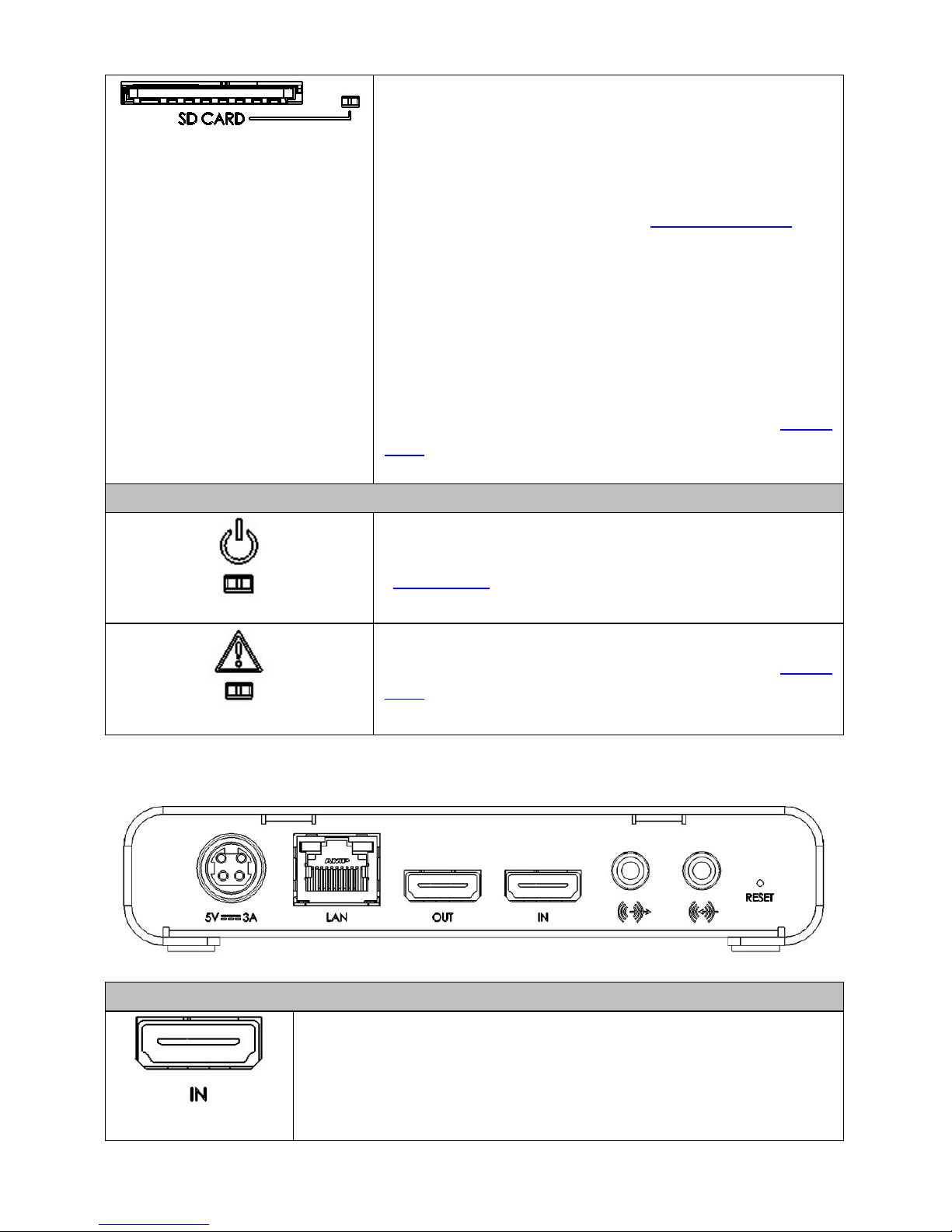
SD Card
Use the SD card slot for
recording the source
connected to the device HDMI input to an SD card.
The NVS-30 supports SD and SDHC cards with FAT32
or NTFS file systems. To select the SD card slot as the
recording destination, see “
Record Settings” in
Chapter 4.
Note: To ensure that your SD card is fast enough to
record at higher bit rates, we recommend using an
SD card with a Class 10 speed rating.
SD Card LED
Indicates the SD card status (see Appendix 1, “Status
LEDs”).
LED
Power LED
Indicates the device power status (see Appendix 1,
“Status LEDs
”).
Error LED
Device error indications (see Appendix 1, “Status
LEDs”).
2.2 Rear Panel
Video Input and Output
HDMI IN
Connect an HD HDMI video source (YUV or RGB) from a digital
HDMI device to this port for streaming and recording.
Note: HDCP and SD sources are not supported on this input.
Page 12
12
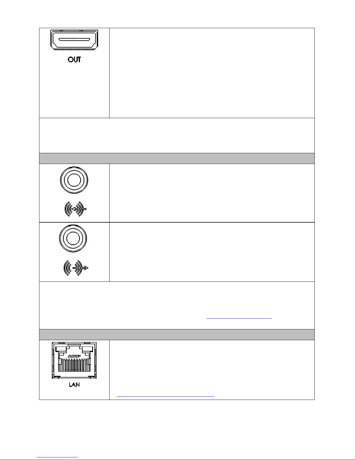
HDMI OUT
Connect an HDMI monitor to this port to preview the HDMI
input, and its first two audio channels if selected as the audio
input source.
Note: HDCP and SD signals are not supported on this output.
The HDMI output supports RGB devices. To monitor your
input source, the HDMI monitor must support the video
input format.
Note: The NVS-30 only supports HD video signals. If you connect an input signal
with a resolution smaller than 1280×720, the NVS-30 will not detect the connected
input, and the video output and web interface will display “No video signal”.
Analog Input and Output
Analog Audio Input
Allows you to input an unbalanced stereo analog audio source
for streaming and recording.
Analog Audio Output
Provides an unbalanced stereo analog audio output for
monitoring the selected audio input source.
Note: The NVS-30 supports the first two channels of uncompressed embedded
audio from the HDMI input source for streaming and recording. You can choose
between the first two audio channels present in the HDMI input or the audio
connected to the NVS-30 analog audio input (see “Audio Input Settings” in Chapter
4).
Others
LAN
The LAN port is an auto-negotiation 10/100/1000 Base-T
Ethernet port which connects the NVS-
30 to an Ethernet
network through a standard RJ-
45 Ethernet cable. For
information on how to connect to a network, see Chapter 3,
“Network Connection and Setup”.
Page 13
13
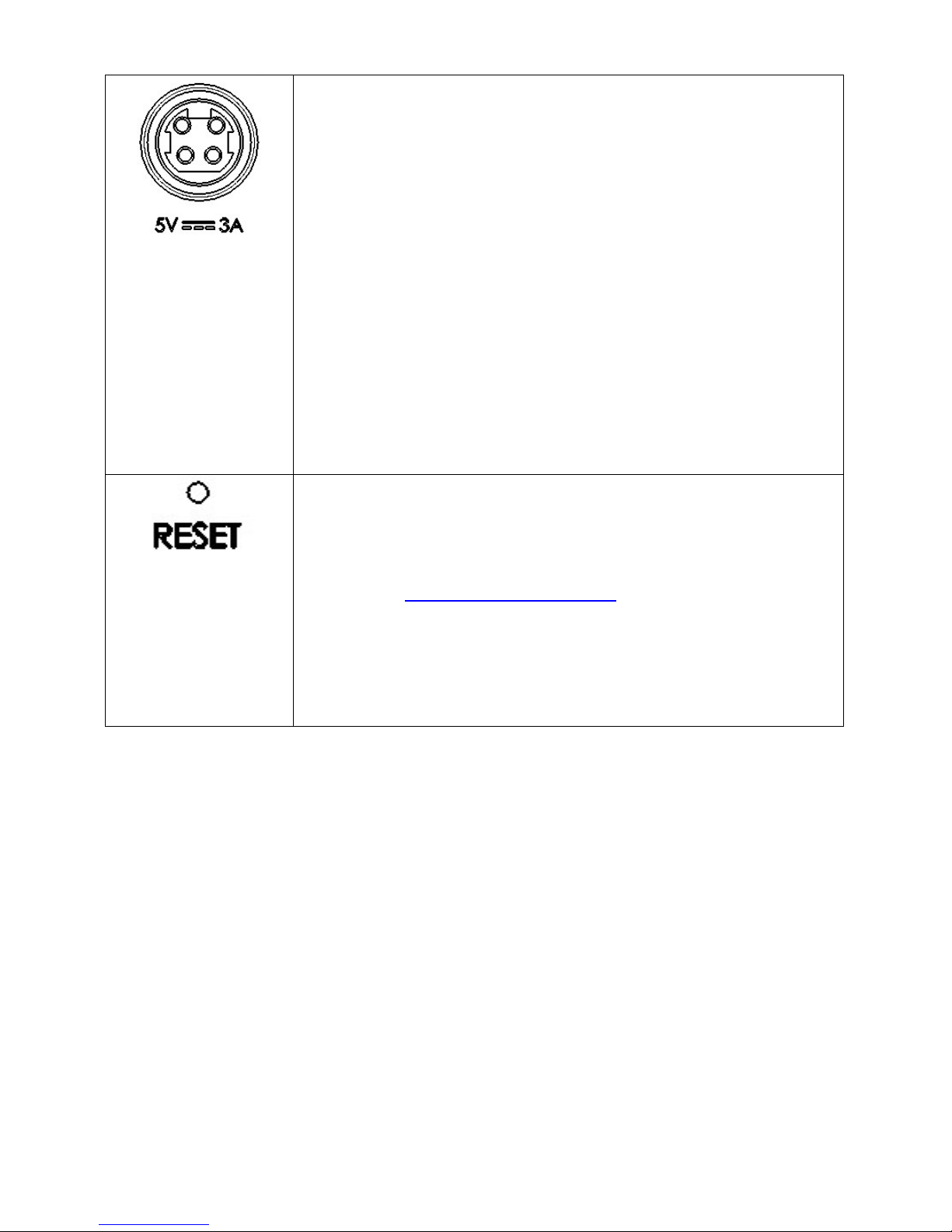
Power
Power the NVS-30 device by connecting the device to an AC
outlet through a power cord and a power adapter. To power
off the NVS-30, simply disconnect the device from the power
source and any logged errors will be
cleared. All current
settings are kept even after the device is powered off.
Note: When power is supplied to the NVS-30
, the device
begins a power-
up sequence during which all LEDs
illuminate. The device is ready when two or more of the
recording destination LEDs (USB port 1, USB port 2, SD Card)
turn off, depending on your record settings.
Power cycle of the NVS-30 performs a simple reboot, not a
reset to factory defaults (see “Device Reboot” in Chapter 6).
Reset Button
You can use the NVS-30 Reset button to reboot the device
(quick button press), or reset the device to factory defaults
(long press of at least five seconds). For more information, see
Chapter 6, “Reset to Factory Defaults
”.
The Reset button is recessed in order to prevent unintended
activation. Use a straightened paper clip, or similar device, to
press the Reset button.
Page 14

14
Chapter 3 Network Connection and Setup
The network connection and setup instructions depend on whether you will be
connecting the NVS-30 to a network with a DHCP server.
If connecting to a network with a DHCP server, the NVS-30 must be set to DHCP
mode. If your network does not have a DHCP server, the NVS-30 must be set to True
Static IP mode. By default, the NVS-30 is set to DHCP mode. Once connected to a
network, configure your stream and record settings using the NVS-30 Command
Center.
To access the Command Center, you must first know the network IP address of the
NVS-30 device or use the Datavideo Utility Software to scan for the device IP. When
connecting to a network with a DHCP server, the NVS-30 IP address is assigned by
the DHCP server. In this case, you can use the Datavideo Utility Software to find the
NVS-30 IP address. When connecting to a network without a DHCP server, you must
assign a static IP address to the NVS-30. A default IP address is provided when in
True Static IP mode.
3.1 Datavideo Utility Software
The Datavideo Utility Software is available for both Mac OS and Windows systems,
and you can use it for the following:
• Identifying NVS-30 devices on a network and lists their IP addresses.
• Open the NVS-30 web based UI (Command Center) by double-clicking an
identified device on the device list.
• Update the NVS-30 firmware (see Appendix 2 “Firmware Update
”).
• Reboot NVS-30 devices (see “Device Reboot” in Chapter 6).
Before launching the Datavideo Utility Software, you must first configure your NVS30’s network settings as well as the PC on which the software is installed. The
subsequent section will take you through the entire network configuration process.
3.2 Network Connection and IP Address
This section details how to connect the NVS-30 to a network with or without a DHCP
server, and describes how to acquire the NVS-30 IP address.
3.2.1 Finding the NVS-30’s current IP address
You must know your NVS-30 device’s IP address to access the Command Center.
There are three ways to find the NVS-30’s current IP address:
• You can see it displayed on an HDMI monitor at device boot up.
Page 15

15
• You can have it automatically saved to a connected USB device when rebooting
the NVS-30.
• Use the Datavideo Utility Software to view all connected NVS-30 devices and
their IP addresses.
Displaying the IP address on an HDMI monitor
The NVS-30’s IP address is displayed on a connected HDMI monitor at device bootup:
1. Connect the NVS-30 to an HDMI monitor.
2. Power up the NVS-30.
When the NVS-30 boots up, the IP address appears on the screen for approximately
30 seconds before being replaced by the passthrough signal.
Saving the IP address and status to USB
You can save a file containing the NVS-30’s IP address and the device’s current status
to a USB device, making this information easily accessible.
1. Insert a formatted USB device into the USB port 2.
2. Reboot your NVS-30 by pressing the Reset button on the device (“Device Reboot
”
in Chapter 6).
3. The NVS-30’s IP address and status information are now saved to a text file on
the USB device.
This file can be helpful if you do not have an HDMI monitor or if you need to share
status information for your unit.
Finding the IP address with Datavideo Utility Software
The Datavideo Utility Software will display the IP addresses of the NVS-30 devices in
your network. See the subsequent sub-section “
Connecting to a network with a
DHCP server (DHCP IP mode)” for details.
Note: In the DHCP network environment, if you switch the network connection
while the NVS-30 is powered, you must power cycle the device to obtain the new
IP address from the DHCP server. To power cycle the device, use the Reset button
on the NVS-30 (see Chapter 6 “Reset to Factory Defaults”).
3.2.2 Connecting to a network with a DHCP server
In this section, you will learn how to use the Datavideo Utility Software to find the IP
address of your NVS-30 device.
1. Connect the NVS-30’s LAN port to a network through an Ethernet cable.
2. Power on the NVS-30 and by default, the NVS-30 is set to DHCP mode.
3. From a computer that is on the same network subnet as your NVS-
30 device, download the Datavideo Utility Software from our official
website http://www.datavideo.cow/
.
Page 16
16
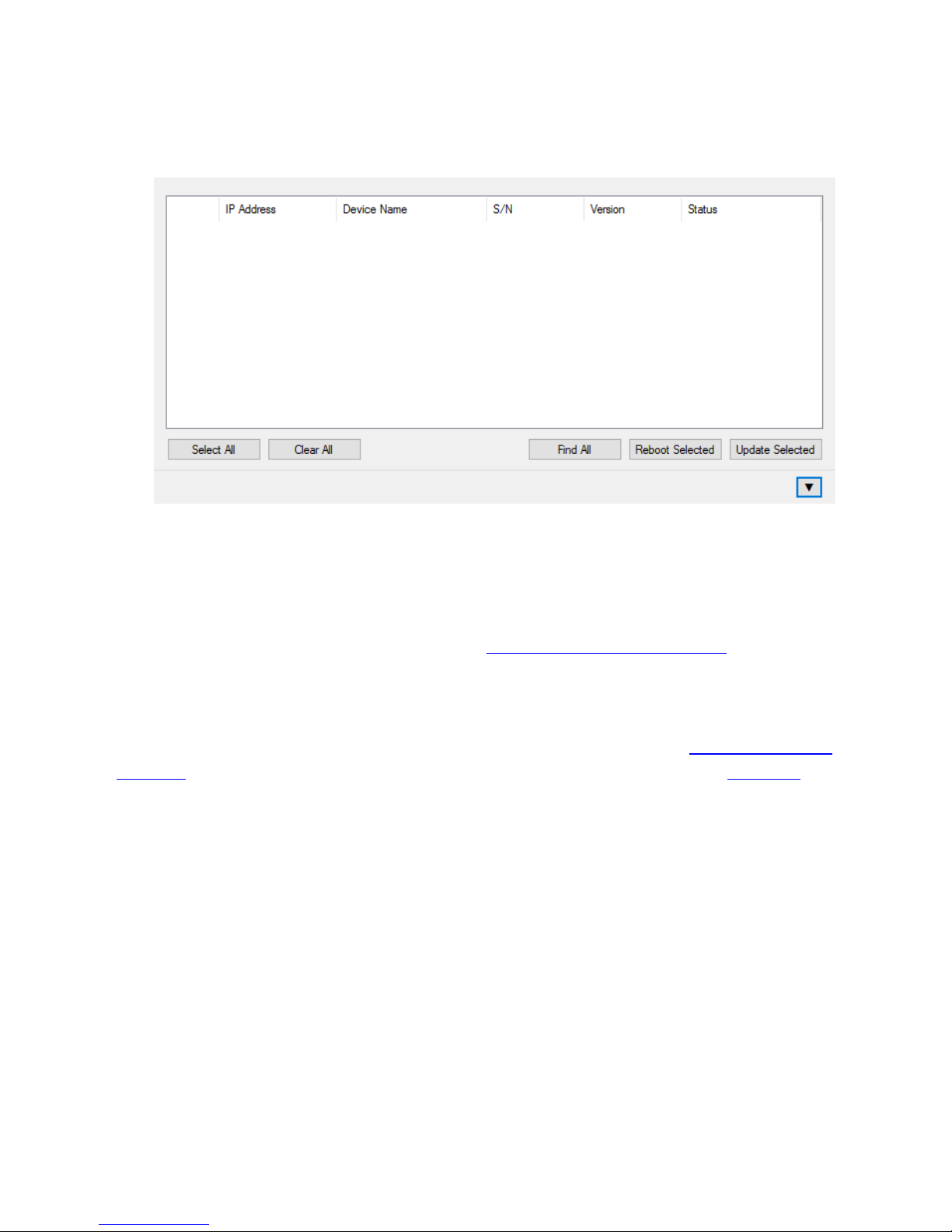
4. Double-click the downloaded Datavideo Utility Software to open the application.
If Universal Plug and Play (UPnP) is enabled on your network, the utility will
automatically scan for NVS-30 devices. To scan manually, click the
Find All
button.
5. All the NVS-30s on the same network subnet as your computer will be displayed,
along with their IP addresses and other information.
6. Open the Command Center (See Chapter 4).
Tip: If you have multiple NVS-30 devices, you may want to change the name of
each device for easier identification (see “Device name and password
” in Chapter
4).
Note: If you need to switch the device from Static IP mode to DHCP IP mode, you
can either reset the device to factory defaults (see Chapter 6 “
Reset to factory
defaults”), or set it to DHCP mode using the Command Center (see “IP Setup” in
Chapter 4).
3.2.3 Connecting to a network withou t a DHCP server (True Static IP)
When connecting to a network without a DHCP server, the network does not assign
an IP address to your NVS-30 device. In this case, you can either manually assign a
static IP address to your NVS-30 device or use the device’s default static IP.
Default Static IP
The default static IP address is designed primarily for the initial setup of the NVS-30
using a point-to-point connection (direct connection between your computer and
the NVS-30). On a network without a DHCP server, the NVS-30 must be set to Static
IP mode. To set to the default static IP, follow the steps outlined below.
1. Power on the NVS-30 and by default, the NVS-30 is set to DHCP mode.
Page 17

17
2. Press the Reset button located on the rear panel of the device to initiate a
device reboot. During the power-up sequence (all LEDs illuminate), the Record
LED flashes for three seconds.
3. Press the Record button on the device while the Record LED is flashing.
4. This sets the device to True Static IP mode and the Static IP address to its default
address (169.254.1.11).
5. The device is ready when two or more of the recording destination LEDs (USB
port 1, USB port 2, SD Card) turn off, depending on your settings.
6. In order for your computer to communicate with the NVS-30, your computer’s IP
address must be in the same network range as your NVS-30’s IP address. Change
your computer’s IP address and subnet mask to the following:
IP address 169.254.1.10
Subnet mask 255.255.0.0
7. Establish a connection between the NVS-30 and your computer using one of the
following methods:
• Connect an Ethernet cable from the NVS-30’s LAN port directly to your
computer’s Ethernet port.
• Connect an Ethernet cable from the NVS-30’s LAN port to the same network
switch as your computer.
8. Open the Command Center (See Chapter 4).
Note: The default IP address is not recommended for a traditional network setting.
If you wish to use the NVS-30 in True Static IP mode over a network, after the
initial setup we recommend that you change the static IP address of the NVS-30
device to an address that is more suitable to your network. You can change the
static IP address in the Command Center as described in “IP Settings” in Chapter 4.
Page 18

18
Chapter 4 Settings – The Command Center
The NVS-30 Command Center is a web-based application that allows you to
configure device settings, control stream and record sessions, and import/export
settings to or from other devices. To open the Command Center, you can do one of
the following:
1. Enter the network IP address of your NVS-30 in your browser to open the
Command Center.
2. On the Datavideo Utility Software, double-click any of the listed devices to open
the Command Center.
4.1 Logging in to the Command Center
The Command Center opens on the Status page. The Status and About pages in the
Command Center can be accessed without logging in. To access any other page, such
as the
Control or Stream Settings page, click the menu item for the page that you
want to access and then enter your username and password. By default, the
username and password are set to admin. The username cannot be changed. If you
wish to change the password for your NVS-30 device, see “Account
” in section 4.4.1.
4.2 Control
The Control page allows you control the streaming and recording for your NVS-30
device. If you have other NVS-30 devices connected to the same network, you can
also control the streaming and recording for up to four other devices at the same
time.
Note: You can also use the Stream and Record buttons directly on the NVS-30
device to stream and record, however, you will not be able to control other devices
on the network.
4.2.1 Accessing the Control page
To access the Control page, open the NVS-30 Command Center and then click the
Control tab.
Page 19

19
4.2.2 Control Buttons
The following table details the different states of the control buttons in the
Command Center.
Button
Function
Stream
Start stream
(RTMP)
Click to Start streaming in RTMP mode.
This button indicates that the NVS-30
device is set to stream in RTMP mode. Click
this button to start streaming the input
source connected to the NVS-30
’s HDMI
input.
If controlling multiple NVS-30 devices,
those devices set to stream in RTMP mode
will begin to stream their input sources as
well.
Page 20

20
Stop stream
(RTMP)
Click to Stop streaming in RTMP mode.
This button indicates that the NVS-30 is
currently streaming in RTMP mode. Click
this button to stop streaming.
If controlling multiple NVS-30 devices,
those devices set to stream in RTMP mode
will stop streaming as well. The devices on
the network that are streaming in RTSP
mode will continue to stream.
Streaming
(RTSP)
An indication that the NVS-
30 device is
currently streaming in RTSP mode.
In RTSP mode, the unit delivers stream data
once a client connects to the NVS-30 using
the RTSP streaming protocol, and therefore
does not require you to click the Stream
button to start streaming.
Stream
disabled
An indication that the NVS-30 is currently
set to Record-only operating mode.
Record
Start record
Click to Start recording
Click this button to start recording the input
source connected to the NVS-30’s HDMI
input.
If controlling multiple NVS-30 devices,
those devices will begin to record their
input sources as well.
Stop record
Click to Stop recording
This button indicates that the NVS-30
device is currently recording its input
source. Click this button to stop recording.
If controlling multiple NVS-30 devices,
those devices will stop recording their input
source as well.
Page 21

21
Record
disabled
Indicates that the NVS-30 is currently set
to Stream-only operating mode.
Stream and Record
Start stream
(RTMP) and
record
Click to start simultaneous streaming and
recording.
This button is available only when the NVS30 is set to stream in RTMP mode. Click this
button to start streaming and recording the
input source connected to the NVS-30’s
HDMI input.
If controlling multiple NVS-30 devices,
those devices will begin to stream and
record their input sources as well.
Stop stream
(RTMP) and
record
Click to stop simultaneous streaming and
recording.
Click this button to simultaneously stop
streaming and recording the input source
connected to the NVS-30’s HDMI input. If
controlling multiple NVS-30 devices, those
devices will stop streaming and recording
their input sources as well.
Note: You can also
use individual Stop
stream and Stop record buttons to stop
the respective operation.
Stream and
record button
disabled
Disabled stream and record button.
The stream and record button is disabled
when the NVS-30
is currently either
streaming or recording, or when the NVS-30
is set to Stream-only or Record-only
operating mode.
Page 22

22
4.3 Settings
Under the Settings tab, you will be able to gain access to the following pages:
• Audio Settings
• Stream Settings
• Record Settings
The subsequent sub-sections will provide an outline of the settings on these pages.
4.3.1 Audio Input Settings
The
Audio Settings page in the Command Center allows you set the audio input
source that will be used for streaming and recording, and the audio sample rate for
your analog audio source. If controlling multiple devices, each device on the network
streams and records the audio based on its own audio settings.
Note: To save changes made in the
Audio Settings page, you must click the Apply
button. If you leave the Audio Settings page before applying the settings, all changes
will be lost.
Accessing the audio settings
To access the audio settings, open the Command Center and then select Settings >
Audio.
Audio source
Select the NVS-30 audio input source that will be used for streaming and recording.
The NVS-30 supports two audio channels for streaming and recording. You can
choose to use either the first two audio channels from your HDMI input source, or
the stereo audio source connected to the NVS-30’s analog audio input (see the
rear
panel section).
The NVS-30 uses the AAC audio format for streaming and recording. To monitor the
selected audio source, you can use either the HDMI or analog audio output.
Page 23

23
Note: You can choose whether or not to include audio for streaming and recording
on the stream and record settings pages respectively.
Analog audio sample rate
If using analog audio, select the desired sample rate for your analog audio input
source. If you are using an HDMI audio input source, this option is unavailable
(appears dimmed) because the sample rate is determined by the digital signal.
The default setting is 48 kHz, but you can choose any of the available options.
The analog audio input is converted to the selected sample rate before encoding.
Selecting the highest sample rate provides the best audio quality, but also increases
the total bit rate required to maintain this quality for streaming and/or recording.
Audio bit rate
Select the bit rate at which you want to stream the audio. This setting applies to both
the stream and record settings.
Note: (Analog audio only) To select the 32 kb/s bit rate, you must first set the Analog
audio sample rate to 22.05 kHz.
4.3.2 Operating Modes
To ensure the highest possible streaming/recording video data rates based on your
needs, the NVS-30 offers three operating modes:
• Stream only: This mode disables the record functionality for your NVS-30. In this
mode, the maximum average video data rate for streaming is set to 20 000 kb/s.
•
Record only: This mode disables the stream functionality for your NVS-30. In this
mode, the maximum average video data rate for recording is set to 30 000 kb/s.
•
Stream and record: This mode allows you to simultaneously stream and record
with your NVS-30 device. In this mode, the maximum average video data rate
for streaming is 10 000 kb/s, and the combined maximum average video data
rate for streaming and recording is 30 000 kb/s. For example, if the average
video data rate for streaming is set to the maximum value of 10 000 kb/s, the
maximum average video data rate for recording is 20 000 kb/s.
Specifying the operating mode
You can set the NVS-30 operating mode on either the
Stream Settings page or Record
Settings
page.
Note: Changes made to the operating mode are automatically and instantly
applied. The “Apply” button in the “Stream Settings” page and “Record Settings”
page does not apply the operating mode setting.
Page 24

24
Stream Settings
The Stream Settings page in the Command Center allows you set the stream settings
for the NVS-30 device. If controlling multiple devices, each device on the network
streams based on its own stream settings. For details on how to start/stop streaming,
see Chapter 5, “Streaming and Recording
”.
Note: To save changes made in the “Stream Settings” page, you must click the
“Apply” button. If you leave the “Stream Settings” page before applying the
settings, all changes will be lost.
Accessing the stream settings
To access the stream settings, open the Command Center and select Settings >
Stream.
Note: The stream settings cannot be modified when the NVS-30 is set to Recordonly mode.
Operating mode
Select the NVS-30 operating mode.
Page 25

25
Stream profiles
The NVS-30 allows you to save up to four stream profiles that you can load at any
time. Saving a new stream profile saves the current encoding and streaming settings.
Saving a stream profile
1. Specify your stream settings.
2. From the Profile list, select an empty profile, or a previously saved profile that you
want to overwrite.
3. Type a Profile name.
4. Click Save.
Loading a stream profile
1. From the Profile list, select a profile.
2. Click Load. The loaded profile will appear next to Loaded profile field. If a change
is then made to any of the stream settings, “(modified)” will appear next to the
loaded profile name.
Encoding options
Specify the following H.264 encoding settings for streaming.
Presets
The NVS-30 comes with predefined presets that you can use to quickly set your
encoding settings. A preset automatically sets all encoding settings, however, you
should verify that the preset frame rate is appropriate for your encoding. You can
also use a preset as a starting point to configure your stream encoding settings.
To use a preset:
1. Select the desired preset from the Preset list.
2. Select the Frame rate.
Note: Some presets may not be compatible for use with all CDNs. To avoid
streaming issues, ensure that the selected preset settings, such as video resolution
and video data rate, are supported by your CDN.
Use stream settings for recording
In Stream-and-record operating mode, check this box to use the stream encoding
settings also for recording.
Video resolution
Select the resolution to which you want to stream by typing values for the
Width and
Height. You can also check the Use input resolution checkbox to stream at your input
source’s original resolution. The NVS-30 does not support upscaling the input source
for streaming.
Page 26

26
Note: In Stream-and-record operating mode, if the current record encoding
resolution exceeds a width of 1280 and/or height of 720, and you want to stream
at a resolution greater than 1280×720, the stream and record settings must use the
same encoding settings. In this case, you must select the Use stream settings for
recording option.
Frame rate
You can choose to stream at your input source’s Full frame rate, or at a Half or a
Quarter of your source’s frame rate.
Note: The NVS-30 does not support upscaling the resolution or frame rate of the
input source. If Full is selected from the Frame rate list, the frame rate will
automatically be set to Half of the input source’s frame rate after clicking Apply.
Target video data rate
Enter the target average video data rate for your stream. When entering an average
data rate, the minimum and maximum data rates are automatically set to 90% and
110% of the average data rate, respectively. The default minimum and maximum
values are applicable in most instances, however, you can change the minimum and
maximum values to suit your needs.
The maximum average video data rate for streaming depends on the selected
operating mode (see the “Operating Modes” section). The NVS-30 uses a variable
data rate when encoding.
GOP size (1-1000)
Type the GOP size (distance between I frames) to which you want to encode your
input source for streaming. The NVS-30 uses the IP pattern when encoding for
streaming. For example, a GOP size of 10 creates a GOP structure of IPPPPPPPPPI.
Include audio
Check the Include audio box to stream the selected audio source along with the
video. The NVS-30 uses the AAC audio format for streaming. Uncheck this box if you
do not want to include audio in your stream.
Advanced settings
Profile sets the H.264 encoding profile for your stream. The available options are
Baseline, Main, and High. Typically, High profile provides the best image quality and
is suitable in most instances. However, depending on the decoder used when
viewing the stream, such as with mobiles devices, a Main or Baseline profile may be
required.
Page 27

27
Frame slices: You can choose to slice each frame into 2, 4, or 8 sections when
encoding, or you can select
1 to encode the frame as a whole. Slicing each frame
when encoding the video for streaming may be useful when a multi-slice decoder
device is used to view the stream.
Deblocking filter: Select this option to improve visual quality and prediction
performance by smoothing the sharp edges which can form between macroblocks
when block coding techniques are used. This filter improves the appearance of
decoded pictures.
Streaming options
The NVS-30 provides RTSP and RTMP streaming protocols for use on Adobe Media
Servers, Wowza Media Servers, software video players such as QuickTime and VLC,
or any of the popular Content Delivery Networks (CDNs), such as YouTube Live and
Ustream.
In RTSP mode, the NVS-30 acts as a streaming server to which clients can connect via
a media server, software video player, or CDN that supports the RTSP streaming
protocol. If you want to stream to more than a handful of clients, we recommend
using a dedicated media server to send streams to clients.
In RTMP mode, the NVS-30 can send stream data to a CDN or media server that
supports the RTMP streaming protocol.
Using the RTSP streaming protocol
1. Select
RTSP.
2. Enter a
Stream name.
3. Enter the network
Port through which the clients will connect.
4. A
Stream URL is automatically generated based on your settings. Provide this
URL to a client to connect to your NVS-30 network via a Wowza Media Server,
software video player, or CDN that supports the RTSP streaming protocol.
5. Enabling jumbo frames can improve data transmission efficiency by sending a
bigger frame of data instead of the standard one. However, use this feature only
Page 28

28
when accessing video files stored on an external media library or storage. Please
note that to use jumbo frames to stream your video you will have to make sure
that every single node on the network has to be jumbo frame enabled or else
the overall network performance will not be improved.
As soon as you apply RTSP stream settings, the NVS-30 is ready to deliver RTSP
streams to clients, and will begin streaming data once a client connects to the NVS30 using the RTSP streaming protocol. The NVS-30 will continue to do so until it is no
longer in RTSP mode. There is no need to use the Stream button located on the
NVS-30 front panel or the Stream button in the Command Center to start
streaming.
If you get choppy video when streaming to VLC media player, you must enable the
Real-time Transport Protocol (RTP) in VLC. Proceed by doing one of the following:
• Windows operating system: Open the VLC media player, select
Tools >
Preferences
, and then click the Input / Codecs tab. In the Network section, select
RTP over RTSP (TCP).
• Mac operating system: Open the VLC media player, select
VLC > Preferences, and
then click the
Input / Codecs tab. In the Codecs / Muxers section, select Use RTP
over RTSP (TCP)
.
Using the RTMP streaming protocol
1. Select RTMP.
2. Specify the destination Server URL and Stream name provided by your CDN or
server administrator.
If your CDN such as Ustream provides a streaming XML file, or when using Wowza
Streaming Engine Manager, you can load the streaming XML file instead of entering
the server URL and stream name. To do so, click
Browse... to select the XML file, and
then click
Load.
When loading a streaming XML file, just the destination information (server URL and
stream name) from the streaming XML file will be loaded. If the streaming XML file
contains encoding information, those settings will not be loaded.
Page 29

29
Clear the Server URL field to remove the XML file. Clear the Stream name field to
remove the loaded streaming XML file.
Please note the following:
• If the stream name, username, or password is included in the stream URL, do
not enter the information in the respective text boxes.
• Streaming XML files are not the same as the NVS-30 configuration XML files.
3. If your Flash-based server or CDN uses the “ModuleRTMPAuthenticate” method
for RTMP authentication, username and password are required for authentication.
However, if username and password information is not included as part of the
stream URL or streaming XML file, you must enter the stream Username and
Password in the text boxes provided.
4. Start streaming the NVS-30 input source to a CDN or media server.
Record Settings
The Record Settings page in the Command Center allows you set the record settings
for the NVS-30 device. The NVS-30 provides settings for recording your input source
for video on demand (VOD), high-quality editing, and archiving/previewing purposes.
Content can be recorded to MOV and MP4 file formats on a FAT32 or NTFS file
system. Because FAT32 limits the recording file size to 4 GB, you must use an NTFS
drive if your recorded file will be greater than 4 GB.
If controlling multiple devices, each device on the network records based on its own
record settings. For details on how to start/stop recording, see Chapter 5,
“Streaming and Recording”.
Note: To save changes made in the Record Settings page, you must click the Apply
button. If you leave the Record Settings page before applying the settings, all
changes will be lost.
Accessing the record settings
To access the record settings, open the Command Center and select Settings >
Record.
Note: The record settings cannot be modified when the NVS-30 is set to Streamonly mode.
Page 30

30
Operating mode
Select the NVS-30 operating mode.
Record profiles
The NVS-30 allows you to save up to four record profiles that you can load at any
time. Saving a new record profile saves the current encoding and recording settings.
Saving a record profile
1. Specify your record settings.
2. From the
Profile list, select an empty profile, or a previously saved profile that you
want to overwrite.
3. Type a
Profile name.
4. Click
Save.
Loading a record profile
1. From the
Profile list, select a profile.
Page 31

31
2. Click Load. The loaded profile will appear next to Loaded profile field. If a change is
then made to any of the record settings, “(modified)” will appear next to the loaded
profile name.
Encoding options
Specify the following H.264 encoding settings for recording.
Presets
The NVS-30 comes with predefined presets that you can use to quickly set your
encoding settings. A preset automatically sets all encoding settings, however you
should verify that the preset frame rate is appropriate for your encoding. You can
also use a preset as a starting point to configure your record encoding settings.
The NVS-30 provides the following preset types:
• HQ: Used for creating recorded files that will be edited for high-quality
production.
• Proxy: Suitable for creating recorded files at smaller file sizes. This is especially
useful when creating files for previewing or archiving, or when recording longduration content.
• YouTube: Used for creating recorded files for delivery to most video on demand
(VOD) streaming applications.
To use a preset:
1. Select the desired preset from the
Preset list.
2. Specify the
Frame rate.
Use stream settings for recording
In Stream-and-record operating mode, check this box to use the stream encoding
settings for recording.
Video resolution
Select the resolution to which you want to record by typing values for the
Width and
Height. You can also check the Use input resolution checkbox to record at your input
source’s original resolution. The NVS-30 does not support upscaling the input source
for recording.
Note: In Stream-and-record operating mode, if the current stream encoding
resolution exceeds a width of 1280 and/or height of 720, and you want to record at
a resolution greater than 1280×720, the stream and record settings must use the
same encoding settings. In this case, you must select the Use stream settings for
recording option.
Page 32

32
Frame rate
You can choose to record at your input source’s Full frame rate, or at a Half or a
Quarter of your source’s frame rate.
Note: The NVS-30 does not support upscaling the resolution or frame rate of the
input source. If Full is selected from the Frame rate list, the frame rate will
automatically be set to half of the input source’s frame rate after clicking Apply.
For example, if your input resolution is 1080p50/59/60, the NVS-30 will
automatically set the frame rate to 1080p25/29.97/30.
Target video data rate
Enter the target
average video data rate for your recording. When entering an
average data rate, the
minimum and maximum data rates are automatically set to 90%
and 110% of the average data rate, respectively. The default minimum and
maximum values are applicable in most instances, however, you can change the
minimum and maximum values to suit your needs.
The maximum average video data rate for recording depends on the selected
operating mode (see the “Operating Modes” section). The NVS-30 uses a variable
data rate when encoding.
GOP structure
Type the
GOP size (distance between I frames) and distance between P frames to
which you want to encode your input source for recording. The NVS-30 uses the IBP
pattern when encoding for recording. For example, a GOP size of 15 and a distance
between P frames of 3 creates a GOP structure of IBBPBBPBBPBBPBBI.
Include audio
Check the
Include audio box to record the selected audio source along with the video.
The NVS-30 uses the AAC audio format for recording. Uncheck this box if you do not
want to record audio.
Advanced settings
Profile sets the H.264 encoding profile for your stream. The available options are
Baseline, Main, and High. Typically, High profile provides the best image quality and
is suitable in most instances. However, depending on the decoder used when
viewing the recorded file, such as with mobiles devices, a Main or Baseline profile
may be required.
Frame slices: You can choose to slice each frame into 2, 4, or 8 sections when
encoding, or you can select 1 to encode the frame as a whole. Slicing each frame
Page 33

33
when encoding the video for recording may be useful when a multi-slice decoder
device is used to view the recorded file.
Deblocking filter: Select this option to improve visual quality and prediction
performance by smoothing the sharp edges which can form between macroblocks
when block coding techniques are used. This filter improves the appearance of
decoded pictures.
Recording options
Configure the following settings for recording.
Media
Select the
Media to which you want to record your input source. You can choose
either a USB port or an SD card slot on the NVS-30 device, or a network location.
Please note the following about using USB devices:
• The NVS-30 writes to all USB devices (including USB 3.0 devices) at USB 2.0
speeds.
• The performance of USB keys or “thumb drives” varies. Many of these devices
are optimized for “read” operations, while the NVS-30 requires sustained “write”
capabilities. For best results, especially at higher recording data rates, powered
USB drives are recommended. In some cases, SD cards may be more suitable
when small portable media is required.
• The NVS-30 supports USB devices with FAT32 or NTFS file systems.
• Media may need to be reformatted if not recognized by the NVS-30.
• USB devices with password protection are not supported.
• It may take a few seconds for the NVS-30 to detect a newly connected USB
device (verified on the status page).
• For USB 3.0 hard drives without a dedicated power supply, the NVS-30 may not
be able to sufficiently power more than one USB 3.0 drive at a time.
• When a recording is stopped, it may take a few moments for the NVS-30 to
finalize the file, during which the USB LED continues to flash. To avoid corrupted
video files, do not remove the USB device when its LED is flashing.
• Connecting a USB device to USB port 2 and then performing a device reboot
allows you to save the NVS-30’s current IP address and status as a text file (see
“Device reboot
” in Chapter 6).
• Connecting a USB device to USB port 2 and then performing a factory reset
allows you to load pre-configured NVS-30 settings (see “Automatic configuration
”
in Section 4.4).
Page 34

34
Please note the following about using SD card:
• It may take a few seconds for the NVS-30 to detect a newly inserted SD card.
• When recording is stopped, the SD card LED continues to flash while the NVS-30
finalizes the file. To avoid corrupted video files, do not remove the SD card when
its LED is flashing.
Maximum recording duration
Enter a
Maximum recording duration to set an overall time limit for your recording
session. The session will automatically end when this limit is reached, or when the
selected storage media is full (whichever occurs first). If you enter a value of 0, the
recording session will continue indefinitely, and will stop only when your storage
media is full.
File switching duration
Enter a File switching duration to separate your recording session into more than
one file at predetermined intervals. For example, if you enter a duration of 30
minutes, the NVS-30 will close the current file and start recording to a new file every
30 minutes.
The size of the created files (in approximated MBs) is displayed next to the duration.
The file size depends on the video data rates you set in the encoding options.
Note
• The maximum file switching duration you can set is four hours and fifty
minutes.
• If you enter a file switching duration of 0, the NVS-30 will automatically switch
to a new file every four hours and fifty minutes. This is a precaution that will
avoid possible data loss that may occur from having files that are too large.
• On FAT32 storage media, file switching will occur automatically after 4 GB is
reached. This is a limitation of the FAT32 file system architecture. You can stop
recording at any time, either by using the control buttons in the Command
Center (see “Control buttons
” in section 4.2), or the Stream and Record
buttons on the NVS-30 front panel.
File type
Select the type of file that will be recorded. You can create either an
MOV or MP4
(MPEG-4) file.
Path and filename
Specify the destination and filename for your recording based on your recording
destination. When specifying the path, all folders in the path must be already existed.
The NVS-30 will not create new folders.
Page 35

35
Each recorded filename contains the base name, date, time, an automatically
incrementing 3-digit number, and file type, using the following naming convention:
Basename-[YYYY-MM-DD_HH-MM-SS].001.mov or .mp4.
Note: Blank spaces are not supported in the base name. Use underscores in place
of blank spaces. For example, enter Recording1_Stage1 instead of Recording1
Stage1 as the base name for the file.
USB or SD card: When recording to a USB device or SD card, enter the folder(s) on
the recording device to which you want to record, if applicable, followed by the base
name. For example, if you want to name your file Recording1, and save the file in a
folder named Files that is contained within another folder named Project on the root
directory, enter Project/Files/Recording1. If you want to save the file in the media
device’s root directory, simply enter Recording1.
Network: Use this option to record your input source to a shared folder on the
network. The method for entering the path and filename depends on the operating
system of the computer that contains the shared folder.
• Windows: When recording to a shared folder that is on the Windows system on
the network, you must enter the IP address of the location on the network to
which you want to record, followed by the shared folder name, and then the
base name for the file in the following format: //IP address/shared folder
name/basename
For example, if you want to name your file Recording1, and save the file to a shared
folder named Files that is located on a network computer with an IP address of
123.456.7.890, enter //123.456.7.890/Files/Recording1.
Note: If the network destination has a firewall, it must be disabled in order to
record to the network location.
• Mac OS X Yosemite: When recording to a shared folder that is on the Mac OS X
Yosemite system on the network, the folder to which you want to save the file
must be shared using the Network File System (NFS) file-sharing protocol. For
information on sharing a Mac OS X Yosemite folder, see “Appendix 4, Sharing a
Mac OS X Yosemite folder using NFS protocol”.
Note: Shared folders that use a file-sharing protocol other than NFS are not
supported with the NVS-30 for recording.
Page 36

36
When entering the path and filename, you must enter the IP address of the location
on the network to which you want to record, followed by the full path to the shared
folder from the root directory, and then the base name for the file in the following
format:
//IP address:/full path to shared folder/basename
For example, if you want to name your file Recording1 and save the file to a shared
folder named Files that is located on the Desktop under Datavideo in the Users root
directory folder on a network computer with an IP address of 123.456.7.890, enter
the following:
//123.456.7.890:/Users/Datavideo/Desktop/Files/Recording1
Tip: You can obtain the full path to the shared folder by right-clicking the folder,
and then clicking Get Info.
Domain, username, and password
When recording your source input to a network location and if the NVS-30 is not on
the same domain as the network, enter the network domain. If required, also enter
the Username and Password that is used to access the network.
5.4 Device
Under the Device tab, you will be able to gain access to the following pages:
• Account
• Date and Time
• Automatic Configuration
• IP Setup
The subsequent sub-sections will provide an outline of the settings on these pages.
4.4.1 Account
The
Account page in the Command Center is where you give a descriptive name to
your NVS-30 device and change your NVS-30 password.
Accessing the Account page
To access the Account page, open the Command Center, and select Device >
Account.
Page 37

37
By default, the device name is set to NVS-30. You can give a unique name to each
NVS-30 device for easy identification within the Command Center and the Datavideo
Utility Software. This is especially useful when you have multiple NVS-30 devices on
the same network. To change the name of your NVS-30, type the desired name in
the
Device name box, and then click Change.
By default, the NVS-30 username and password are set to admin. The device
username cannot be changed, however, we do suggest that you change the device
password. To change the NVS-30 password, enter the current and new passwords
and then click
Change. For information on resetting the password to factory default,
see Chapter 6 “Reset to factory defaults”.
4.4.2 Date and Time
The Date and Time page in the Command Center allows you set the date and time
for your NVS-30 device. You can set the date and time manually or automatically by
using an NTP server. The date and time are used in the naming of the recorded files.
Note: To save changes made in the Date and Time page, you must click the Apply
button. An NVS-30 hardware reboot is required to apply the changes. If you leave
the Date and Time page before clicking Apply, all changes will be lost.
Accessing the Date and Time page
To access the Date and Time page, open the Command Center, and select Device >
Date and Time.
Page 38

38
Setting the date and time manually
1. Select Manual.
2. Set the Time, and enter a Date in the format DD/MM/YYYY, or click to select a
date from the calendar.
3. Click Apply. You’ll be notified that the NVS-30 will be rebooted in order to apply
the changes.
Setting the date and time automatically
Setting the date and time automatically requires a local or public NTP server address.
An Internet connection is required to use a public NTP server.
1. Select Automatic.
2. Enter a local or public NTP server address. The default NTP server address is
time.nrc.ca.
3. Select a Time zone from the list. The current date and time associated with the
selected NTP server and time zone are displayed next to the Current date and time
field.
4. Click Apply. You’ll be notified that the NVS-30 will be rebooted in order to apply
the changes.
4.4.3 Automatic Configuration
The Automatic configuration page in the Command Center is where you can export
the current NVS-30 settings to an XML file (called the NVS-30 configuration file). You
can also import settings from a previously-created configuration file, or import
settings from the same XML file hosted on a web page.
Page 39

39
When you have an NVS-30 configuration file, you can copy it to a USB device,
connect the device to the USB port 2, and then perform a factory reset to
automatically load the settings. For more information on performing a factory reset,
see Chapter 6 “Reset to Factory Defaults
”.
The option to boot up the NVS-30 with all settings loading automatically from a
USB device, or loading settings from a web page URL at device reboot, allows you to
deploy other NVS-30 devices without logging in to the Command Center.
Accessing the Automatic configuration page
To access the Automatic configuration page, open the Command Center and select
Device > Automatic configuration.
Loading settings from an NVS-30 configuration file
You can import NVS-30 settings from a previously-generated NVS-30 configuration
file. The file must be located on your computer or somewhere that is accessible from
your computer.
1. Go to the Automatic configuration page of the Command Center.
2. Under Load settings from an NVS-30 configuration file, click the Browse button.
3. Select the file you want to load.
4. Click Load.
Your NVS-30 settings will now match those of the chosen configuration file.
Loading settings from a web page URL
You can import settings from a specific web page that is hosting the configuration file
generated in the Command Center. This option is particularly useful when there is a
need to oversee the NVS-30 operation from a central control environment. You can
Page 40

40
set bit rates and destinations by managing a web page instead of logging into the
Command Center.
1. Go to the Automatic configuration page of the Command Center.
2. In the Load settings from a web page URL field, type the URL address of a page
hosting the configuration parameters.
3. Click Load.
4. (Optional) Check Load settings at device reboot checkbox if you want to have your
NVS-30 automatically load the settings from the specified URL the next time it boots
up.
Your settings will now match those of the chosen configuration file.
Note: With the Load settings at device reboot checkbox checked, you only need to
reboot/reset your NVS-30 and it checks the specified URL for updated settings.
Generating a configuration file
You can export your current settings as an NVS-30 configuration file, which you can
then save to your computer, to a USB device connected to your computer, or to a
network drive. You can then use the configuration file to configure other NVS-30
devices.
Note: You cannot save to a USB device connected to the NVS-30.
1. Go to the Automatic configuration page of the Command Center.
2. Under Export current settings to an NVS-30 configuration file, click Generate file.
3. Select a save location. Do not change the filename (NVS-30Settings.xml) if you
plan to automatically configure an NVS-30 from a USB device (see the subsequent
subsection “Automatically importing NVS-30 settings on factory reset”).
4. The NVS-30 configuration file is created, and contains all the NVS-30 settings as
XML parameters.
Automatically importing NVS-30 settings on factory reset
On factory reset, the NVS-30 can automatically import configuration settings from an
NVS-30 configuration file that is on a USB device connected to NVS-30’s USB port 2.
1. Copy the NVS-30 configuration file to a USB device.
Note: The configuration file must have the original filename, given by the NVS-30
when the file was generated (NVS-30Settings.xml).
2. Connect the USB device to the NVS-30's USB port 2.
3. Perform a factory reset by pressing and holding the Reset button for at least five
seconds.
Page 41

41
4. The NVS-30 boots up with your settings loaded.
4.4.4 IP Setup
The IP Setup page in the Command Center allows you switch the NVS-30 IP mode
between DHCP and True Static IP. By default, the NVS-30 is set to DHCP mode.
Changing the IP mode will end the current Command Center session. To access the
NVS-30 Command Center again, you’ll need to enter a different NVS-30 IP address in
your browser’s address field. If switching to the True Static IP mode, you may also be
required to change your computer’s network configuration. For information on
obtaining the NVS-30’s IP address and accessing the Command Center in DHCP or
True Static IP mode, see Chapter 3, “Network Connection and Setup
”.
Accessing the IP Setup page
To access the IP Setup page, open the Command Center and select Device > IP Setup.
Setting the IP mode to DHCP
Set the NVS-30 to DHCP mode when connecting to a network with a DHCP server,
such as through a router.
1. Select DHCP.
2. Click Apply.
3. See Section 3.2 “Network connection and IP address
” for instructions on how to
connect the NVS-30 to a network with a DHCP server, and how to acquire the NVS-30
network IP address to access the Command Center.
Setting the IP mode to Static
Set the NVS-30 to Static IP mode when connecting to a network without a DHCP
server.
1. Select Static.
2. Enter a static IP address for your NVS-30. Unless you change this address, the
default static IP address will be used (169.254.1.11). If you reset the device in Static
Page 42

42
IP mode (see “Default Static IP” section), the static IP address will be reverted to the
default.
Note: When connecting multiple NVS-30 devices on the same network, each NVS30 device must have a unique network IP address.
3. Enter the Subnet mask on your network to which the NVS-30 is connected. By
default, the subnet mask is set to 255.255.255.0.
4. Enter the Gateway IP address and DNS server.
5. Click Apply.
6. See Chapter 3, “Network Connection and Setup
” for instructions on how to
connect the NVS-30 to a network without a DHCP server, how to change your
computer’s network configuration to establish a connection between your computer
and the NVS-30 device, and how to access the Command Center.
Preventing the NVS-30 from appearing as a UPnP device on the network
The NVS-30 uses the Simple Service Discovery Protocol (SSDP) to broadcast itself as a
Universal Plug and Play (UPnP) device. This means that it will appear in Windows
Explorer (not visible in Mac OS) as if it were a printer, external hard drive, or similar
UPnP device.
This feature is enabled by default, and makes it easier to find the NVS-30 on the
network if you do not know the device’s IP address. However, for security reasons
you may not want the NVS-30 to appear on your network for anyone to see. If so,
you can disable SSDP to hide the NVS-30 from appearing as a UPnP device.
To prevent the NVS-30 from appearing:
1. Open the Command Center.
2. Choose Device > IP Setup.
3. Clear Display this NVS-30 on the network as a UPnP device.
4. Click Apply.
The NVS-30 will no longer be visible in Windows Explorer as a UPnP device. You may
need to restart Windows Explorer for the NVS-30 to no longer appear on the
network.
Note: By using this option, this NVS-30 device will not automatically appear on the
Datavideo Utility Software list of connected devices. You must use the Find All
button for the NVS-30 to appear.
4.4.5 About
The About page in the Command Center allows you to see the current firmware
version of your NVS-30 device, provide a link to the NVS-30 documentation, and
display the Datavideo Limited Warranty for the NVS-30.
Page 43

43
This page can be viewed without logging in.
Accessing the About page
To access the About page, open the Command Center and select Device > About.
Firmware version
Displays the current firmware version of your NVS-30 device. To update the NVS-30
firmware, see Appendix 2 “Firmware Update
”.
Documentation
You can access PDF versions of the latest NVS-30 documentation by clicking the link
on the
About page. An Internet connection is required.
4.5 Status
The Status page in the Command Center provides a summary of the NVS-30 status
and settings, as well as any logged errors. This page can be viewed without logging in.
Accessing the Status page
To access the Status page, open the Command Center and select Status.
Page 44

44
NVS-30 errors
When a streaming or recording error occurs, the LED illuminates on the NVS-30
device. Unless you receive a pop-up error when using the buttons in the Command
Center’s
Control page, the error will be logged in the Messages section (Status page).
Note: An error will not be reported if the audio connected to the NVS-30’s analog
audio input is lost or missing. If this occurs, the stream and/or recording continues
but will not contain audio.
Viewing and clearing errors
Streaming and recording errors that do not appear as a pop up error on the Control
page are instantly logged in the Messages section of the Status page.
The Status page displays the errors pertaining to that NVS-30 device only.
To monitor streaming and/or recording when controlling multiple devices, we
recommend that you open the Command Center for each NVS-30 device.
When you click the Clear messages button on the Status page, the logged errors are
deleted from the list and the LED turns off. The LED will also turn off if you
successfully start a new stream and/or recording.
Note: Powering off or resetting the NVS-30 will clear all errors from the device.
Page 45

45
Chapter 5 Streaming and Recording
The NVS-30 allows you to stream and record the input source connected to the NVS30’s HDMI input. If you have multiple NVS-30 devices connected to the same
network, you can also control the streaming and recording of multiple devices from
one device’s Command Center.
Unless a specific record duration limit was set in the record settings, NVS-30 limits
the duration of each recording to four hours and fifty minutes. The recording will
automatically stop when the duration limit is reached.
When a recording is stopped, it will take a few seconds for the NVS-30 to finalize the
file. If recording to a USB device or SD card, the USB/SD card LED continues to flash
during the finalization process. To avoid corrupted video files, do not remove the
USB device or SD card when its LED is flashing.
5.1 Streaming and Recording on a Single Device
To control streaming and recording for a single NVS-30 device, you can use the
following two methods:
1. Use the control buttons in the Command Center (see “Control buttons
” in
section 4.2).
2. Use the Stream and Record buttons on the NVS-30 device (see Chapter 2,
“Connections and Controls
”).
5.2 Streaming and Recording on Multiple Devices
The NVS-30 allows you to start and stop the streaming and recording for up to five
devices on the network at the same time. Each device streams and records the input
source connected to its HDMI input based on its own stream and record settings. To
control multiple devices, you must use the control buttons (see “Control buttons
” in
section 4.2) in the Command Center instead of the Stream and Record buttons
located on NVS-30 front panel, which control the streaming and recording for that
device only.
You can control multiple NVS-30 devices from any of the devices on the network.
When enabling the control of multiple devices in a device’s Command Center, that
device becomes the primary device and the devices being controlled become
secondary devices. The control buttons in the Command Center of the primary
device can then be used to control the other devices on the network. You can have
more than one primary device on the network, with each primary device controlling
its secondary devices. For example, if you have three NVS-30 devices on the network,
you can set device one to control devices two and three, and you can also set device
Page 46

46
two to control devices one and three. For details on enabling multi-device control in
an NVS-30’s Command Center, and using the control buttons to stream and record,
see “Command Center Control
” page.
5.3 Disable Stream and Record buttons on the front panel
You can disable the physical Stream and Record buttons on the NVS-30 device to
prevent someone from inadvertently stopping a streaming or recording session. This
option only applies to the NVS-30 you are connected to, and not other NVS-30
devices you may be controlling.
To disable the Stream and Record buttons:
1. In the Command Center, click Control.
2. Select Disable Stream and Record buttons on this NVS-30 device. The Stream and
Record buttons on the NVS-30 device are disabled.
Note: This button disable feature is off by default.
5.4 Enabling multi-device control
This section details how to enable multi-device control of up to four other devices in
the Command Center.
1. In the Command Center, click Control.
2. Select Control multiple NVS-30 devices.
3. For each NVS-30 device that you want to control, enter the network IP address of
the device. Click Scan after entering the IP address to verify if the device can be
found on the network. For information on acquiring the NVS-30’s IP address, see
Section 3.2 “Network connection and IP address
”.
4. Activate or deactivate the control for an NVS-30 device by selecting or clearing the
device’s Active box.
Page 47

47
Chapter 6 Reset to Factory Defaults
This chapter describes how to reset the NVS-30 device using the Reset button
located on the device’s rear panel. At times you may want to reset current NVS-30
settings to factory defaults, please follow the steps outlined below to perform
factory reset.
1. Use a paper clip to press and hold the Reset button on the rear panel for at least
5 seconds.
2. The device begins a power-up sequence during which all LEDs illuminate.
3. The device is ready when all LEDs turn off except the Power, Stream, Record,
and USB port 1 LEDs.
When resetting the NVS-30 using this method, the following device settings will be
reset to factory defaults.
• Device’s login credentials reset to admin.
• The device network setting reset to DHCP mode.
Note: You may switch the device to Static IP mode after performing a factory reset
or a simple device reboot, see “Default Static IP” section in Chapter 3.
You can also use a factory reset to load pre-configured NVS-30 settings from a
configuration file. For more information, see “Automatic configuration
” in Chapter 4.
6.1 Device Reboot
The Reset button also allows you to perform device reboot. Perform the following to
reboot the device.
1. Use a paper clip to press the recessed pinhole Reset button on the rear panel.
2. The device begins a power-up sequence during which all LEDs illuminate.
3. The device is ready when two or more of the recording destination LEDs (USB
port 1, USB port 2, SD Card) turn off, depending on your settings.
4. Open the Datavideo Utility Software, and select the NVS-30 device you wish to
reboot, and then click Reboot Selected.
Note: When performing a device reboot, all current settings are kept, including the
IP setting (DHCP or Static IP) that was set prior to the reboot, and only logged
errors are cleared.
If you have a USB device connected to the NVS-30 USB port 2, the current device’s IP
address and status will be saved to the USB device as a text file. This is a convenient
way to find the device’s IP address.
Page 48

48
Chapter 7 Appendices
Appendix 1 Status LEDs
LED
State
Condition
Green Device is powered.
Yellow
Indicates that a streaming and/or
recording error has occurred, including a
physical disconnect of the network cable.
OFF
• Error cleared.
• Network cable reconnected.
• A new stream/recording is successfully
started.
STREAM
OFF
Device in Record-Only
mode. In this
mode, Stream button is disabled.
Solid Blue Stream in RTSP or RTMP mode.
Flashing Blue
Streaming in progress.
In RTSP
mode, flashing Stream LED
indicates that a client is currently
connected to the device.
In RTMP
mode, flashing Stream LED
indicates a stream is started by pressing
the Stream button on the device or the
control buttons in the Command Center.
In Stream-only mode, the Stream LED
will flash faster when disconnection
occurs, which indicates that the device
attempts to reconnect. The Stream LED
will resume the regular flashing speed
once the connection is re-established.
RECORD
OFF
Device in Stream-Only mode. In this
mode, Record button is disabled.
Solid Red
Device set to record to the selected
media.
Flashing Red
Recording in progress.
STREAM/RECORD
Solid Blue
Indicates Stream Disconnected when
Stream and Record modes are turned ON
at the same time.
Page 49

49
Note: The device will not try to re-
establish the connection and the LEDs
will stay solid blue until the stream is
manually restarted.
USB Ports 1/2
OFF
The USB port is not selected as the
recording media. Device set to Stream-
Only mode.
Solid Red
The USB port is selected as the recording
media.
Flashing Red
The device is currently writing to the
media device connected to the USB port.
Note: Do not remove the USB device
while the USB port LED is flashing as
doing so may result in corrupted video
files.
SD Card
OFF
The SD card is not selected as the
recording media. Device set to Stream-
Only mode.
Red (Solid)
The SD card is selected as the recording
media.
Red (Flash)
The device is currently writing to the SD
card inserted in the SD card slot.
Note: Do not remove SD card while the
SD card LED is flashing as doing so may
result in corrupted video files.
Page 50

50
Appendix 2 Firmware Update
Datavideo usually releases new firmware containing new features or reported bug
fixes from time to time. Customers can either download the NVS-30 firmware as they
wish or contact their local dealer or reseller for assistance.
This section outlines the firmware upgrade process which should take approximately
10 minutes to complete.
The existing NVS-30 settings should persist through the firmware upgrade process,
which should not be interrupted once started as this could result in a non-
responsive unit.
Successful firmware upgrade on NVS-30 requires:
The latest firmware file, which can be obtained from your local Datavideo dealer
or office.
A MAC or PC computer with web browser on the same IP network as the NVS-30.
Datavideo Utility Software
(can be downloaded from Datavideo’s official website)
The current NVS-30 IP address and settings (Network Connection and IP Address)
1. Power ON NVS-30 and connect it to an Ethernet network.
2. Open Datavideo Utility Software on a computer that is on the same network
subnet as the NVS-30 that you want to update.
Note: You cannot update the NVS-30 firmware over a wireless network.
3. On the Datavideo Utility Software, select the network
IP Address of the NVS-30
device that you want to update, and then click
Update Selected.
4. If you have multiple NVS-30 devices on the network, select the IP address for
every device on the Datavideo Utility Software by clicking
Select All, and all NVS-
30 devices will be updated in sequence.
Note: The NVS-30 device will be turned on and off at different times during the
update process. The update is complete when all LEDs are turned off except the
Power, Stream, Record, and USB port 1 LEDs.
It is not recommended to simultaneously update the same NVS-30 device using
more than one instance of the Datavideo Utility Software.
Page 51

51
Appendix 3 Recording file sizes and duration
The following tables list the approximate recording file size based on the average
video data rate and recording duration, and the approximate maximum recording
duration given the average video data rate and available disk space.
Note: Unless a specific recording duration limit was set in the record settings, the
NVS-30 limits the duration of each recording to four hours and fifty minutes. The
recording will automatically stop when the duration limit is reached.
Approximate file size
Recording
Duration
Average Video Data Rate (kb/s)
500
2000
5000
15 000
25 000
5 min
18.8 MB
75 MB
188 MB
563 MB
938 MB
30 min
112.5 MB
450 MB
1.1 GB
3.4 GB
5.6 GB
60 min
225 MB
900 MB
2.3 GB
6.8 GB
11.3 GB
3 hrs
675 MB
2.7 GB
6.8 GB
20.3 GB
33.8 GB
4 hrs 50 min
1.1 GB
4.5 GB
11.3 GB
33.8 GB
56.3 GB
Approximate maximum recording duration
Disk Space
Average Video Data Rate (kb/s)
500
2000
5000
15 000
25 000
4 GB
17.8 hrs
4.4 hrs
107 min
36 min
21 min
16 GB
71.1 hrs
17.8 hrs
7.1 hrs
2.4 hrs
85 min
32 GB
142.2 hrs
35.6 hrs
14.2 hrs
4.7 hrs
2.8 hrs
64 GB
284.4 hrs
71.1 hrs
28.4 hrs
9.5 hrs
5.7 hrs
256 GB
1138 hrs
284.4 hrs
114 hrs
38 hrs
22.8 hrs
1 TB
4444.4 hrs
1111.1 hrs
444.4 hrs
148.1 hrs
89 hrs
Page 52

52
Appendix 4 Sharing a Mac OS X Yosemite folder using NFS protocol
To record to a shared folder that is on a Mac OS X Yosemite system on the network,
the folder must be shared using the Network File System (NFS) file-sharing protocol
as explained below.
Note: To share a folder using the NFS protocol, the full path to the folder that you
want to share is required. You can obtain the full path to the folder by rightclicking the folder, and then clicking Get Info.
1. On the computer that contains the folder that you want to share, make sure that
you're logged in as an administrator and that your user account has a password. User
accounts that do not have a password cannot be used to share a file using the NFS
protocol.
2. In the Finder menu, choose File > New Finder Window.
3. In the Applications folder, click the Utilities folder, and then click Terminal.
4. In the Terminal window, type the following command, where “Path” is the full
path to the folder that you want to share:
echo /Path -mapall=$(logname)| sudo tee /etc/exports
For example, to share a folder named Files that is located on the Desktop under
Datavideo in the Users root directory folder, type the following command:
echo /Users/Datavideo/Desktop/Files -mapall=$(logname)| sudo tee /etc/exports
For added security, you can restrict write access to the folder to one device by
adding the IP address of the NVS-30 that you want to use to write to the folder. For
example, if the IP address of the NVS-30 device is 169.254.1.11, type the following
command:
echo /Users/Datavideo/Desktop/Files 169.254.1.11 -mapall=$(logname)| sudo tee
/etc/exports
5. Press ENTER.
6. Type your user account password, and then press ENTER.
7. Type the following command:
Page 53

53
sudo nfsd restart
8. Press ENTER.
9. Close the Terminal window.
Page 54

54
Appendix 5 Frequently-Asked Questions
This section describes problems that you may encounter while using NVS-30. If you
have any questions, please refer to related sections and follow all suggested
solutions. If problem still exists, please contact your distributor or the service center.
No.
Problems
Solutions
1.
How to remove blocky artifacts on the
streaming video?
Block artifacts could be due to low
quality stream settings for example
bitrate below 300kbps. To remove the
blockiness, please enable the deblocking
filter option on the Stream Settings page.
Please see page 24 for details on how to
enable deblocking filter.
Page 55

55
Appendix 6 Dimensions
All measurements in millimeters (mm)
Page 56

56
Appendix 7 Specifications
Video and Audio Input / Output
HDMI Video Input
1920x1080p @ 60/59.94/50/30/29.97/25/24/23.98
1920x1080i 29.97/25
1280x720p@ 60/59.94/50 Frames per second
Video Input Format is Auto-Detected
HDMI Video Output
Preview output of video input signal.
2 Frame delay from input to output.
Audio Input
Processes first two channels of audio embedded in HDMI
input signal.
Unbalanced analog stereo input via 1/8” (3.5mm) jack.
Line Level
Audio Output
Pass through of all embedded audio channels in HDMI signal.
Unbalanced analog stereo output via 1/8” (3.5mm) jack –
pass through of input.
Line Level
H.264/MPEG-4 Part 10 (AVC) Video Encoder
Resolutions
Selectable encoding resolutions ranging from:
128x128 to 1920x1080
Bit Rates Ranges
Record Only Mode: 100 kbps to 30 Mbps
Stream Only Mode: 100 kbps to 20 Mbps
Independent Stream and Record Mode**:
Recording: 100 kbps - 30 Mbps
Streaming: 100 kbps - 10 Mbps
Maximum combined total bitrate of 30 Mbps
**Note that when both streaming and recording resolutions
are above 1280x720, the encode parameters must be
identical for both processes. Completely Independent
recording and streaming settings are available when either
the streaming or the recording resolution is 1280x720 or
below.
Encode Frame Rates
Encode frame rates representing 1:1, ½ and ¼ of the input
frames rates are supported
Note that the maximum encode frame rate is 30 fps when
encode resolution is 1920 x 1080
Encoding Profiles
Baseline, Main and High
Encoding Controls
2.0, 3.0, 3.1, 4.0, 4.1 Level Support
GOP Size and Structure
Page 57

57
Variable bit rate support
Average max/min data rate controls
Deblocking Filter
MPEG-4 AAC Audio Encoder
Standard
AAC-LC
Sample Frequency
22.5, 32, 44.1 and 48 kHz when digitized from analog source
Channels
2 channels Stereo (L/R)
Bit Rates
Range from 32 kbps to 256 kbps
Scaler
High Quality multi-tap 10 bit Down Scaler and De-Interlacer.
Available to both streaming and recording operations.
Recording File Format
File Type
Industry Standard MP4 and MOV files with two channels of
embedded AAC audio.
Recording Lengths
Maximum file length of 300 minutes - irrespective of storage
type used. File splitting feature allows a user to record
continuously for long periods by defining file segment sizes.
The NVS-30 will create these sequential file segments over
the course of the recording operation without losing a single
frame of video. File segment can have a length of 1 to 300
minutes.
Network Interfaces
Connector
RJ45 providing 10/100/1000 Base-T Ethernet with Static or
DHCP addressing
Protocols
RTMP, RTSP/RTP
IPv4 Support
Unicast and Multi Unicast (number of clients may vary from 3
to 10)
User Interface
Physical Interface
Independent streaming and recording Start/Stop control
Storage Types for File Recording
2 x USB 2.0
Support for NTFS (3.1) and FAT32 file system
The NVS-30 will support writing to USB3 devices at USB2
speeds. Also note, there is a very high variability in the
performance capabilities of “thumb” drives (even USB3
versions). Many are optimized for “read” operations while the
NVS-30 requires sustained “write” capabilities. For best
results, NVS-30 recommends using powered USB drives. If
small portable media is required, SD cards may be more
suitable.
1 x SD card Slot
Supports SD and SDHC cards. Only NTFS formatted SDXC
Page 58

58
cards are supported. (Class 10 highly recommended).
Network Mapped
Drive
Support for writing to shared folders in computers found on a
network using Windows Share protocols (suitable for
windows system) as well as NFS protocols (suitable for Mac
and Linux systems).
Physical
Dimensions
5.60 in. long (14.2 cm)
4.30 in. deep (10.9 cm) excluding inserted SD-CARD
4.40 in. deep (11.2 cm) including inserted SD-CARD
1.22 in. (3.1 cm) high including rubber feet
Weight
0.66 lbs (300 grams) excluding power supply
Operating
conditions
32 to 104 deg. F (0 to 40 deg. C), 20 to 80% relative humidity
(non-condensing)
Transport and
Storage
Max Operating Altitude: 3000 meters
Max Transport altitude: 12,000 meters
Storage Humidity 5 to 95% relative humidity (non-
condensing)
Page 59

59
Service and Support
 Loading...