

Page 1

HDBaseT PORTABLE
HS-1600T
VIDEO STREAMING STUDIO
4 CHANNEL HD/SD
Instruction Manual
Page 2

Table of Contents
FCC COMPLIANCE STATEMENT............................................................................................................. 5
WARNINGS AND PRECAUTIONS ........................................................................................................... 5
WARRANTY .......................................................................................................................................... 6
STANDARD WARRANTY............................................................................................................................ 6
THREE YEAR WARRANTY .......................................................................................................................... 6
DISPOSAL ............................................................................................................................................. 7
CHAPTER 1 INTRODUCTION ............................................................................................................... 8
1.1 FEATURES .................................................................................................................................. 8
1.2 SYSTEM DIAGRAM ....................................................................................................................... 9
CHAPTER 2 CONNECTIONS AND CONTROLS .................................................................................... 10
2.1 REAR PANEL ............................................................................................................................. 10
2.2 SWITCHER KEYBOARD PANEL ........................................................................................................ 12
2.3 MONITOR CONTROL PANEL ......................................................................................................... 20
2.4 STREAMING CONTROL PANEL ....................................................................................................... 21
CHAPTER 3 SWITCHER OSD MENU .................................................................................................. 22
3.1 START ..................................................................................................................................... 22
3.1.1 Transition Type.................................................................................................................. 22
3.1.2 Transition Speed ................................................................................................................ 22
3.1.3 Wipe Effect........................................................................................................................ 23
3.1.4 WIPE Border Size ............................................................................................................... 23
3.1.5 WIPE Border Color ............................................................................................................. 23
3.1.6 BKG Color .......................................................................................................................... 23
3.2 PIP / SPLIT .............................................................................................................................. 23
3.2.1 PIP Source ......................................................................................................................... 24
3.2.2 PIP Size (PIP Window Size) ................................................................................................. 24
3.2.3 Position X .......................................................................................................................... 25
3.2.4 Position Y .......................................................................................................................... 25
3.2.5 Split Source ....................................................................................................................... 25
3.2.6 Border Size ........................................................................................................................ 25
3.2.7 Border Color ...................................................................................................................... 25
3.3 PIP CROP ................................................................................................................................ 25
3.4 LUMAKEY................................................................................................................................. 26
3.4.1 Lumakey Source ................................................................................................................ 26
3.4.2 Mode ................................................................................................................................ 27
3.4.3 Cleanup Level .................................................................................................................... 27
3.4.4 Transparency .................................................................................................................... 27
3.5 AUDIO .................................................................................................................................... 27
3.5.1 Mute ................................................................................................................................. 27
2
Page 3

3.5.2 HDMI Input ....................................................................................................................... 27
3.5.3 HDMI Group ...................................................................................................................... 27
3.5.4 Level.................................................................................................................................. 27
3.5.5 Tally Mode ........................................................................................................................ 28
3.6 USER MEMS............................................................................................................................. 28
3.6.1 Load Memory .................................................................................................................... 28
3.6.2 Save Memory .................................................................................................................... 28
3.7 SETUP ..................................................................................................................................... 28
3.7.1 PGM Out Res. .................................................................................................................... 29
3.7.2 MV Out Res. ...................................................................................................................... 29
3.7.3 Save Setup......................................................................................................................... 30
3.7.4 Factory Default ................................................................................................................. 30
3.7.5 Language .......................................................................................................................... 30
3.7.6 MB and KBD Software ....................................................................................................... 30
3.8 CAMERA .................................................................................................................................. 30
3.8.1 Camera CH. Setup ............................................................................................................. 31
3.8.2 PTC-150T-01/02/03 ........................................................................................................... 31
Camera Info ............................................................................................................................. 31
Video ....................................................................................................................................... 31
Operator .................................................................................................................................. 32
CHAPTER 4 MONITOR ...................................................................................................................... 33
4.1 MENU OPTIONS ...................................................................................................................... 33
4.1.1 MAIN ADJUST .................................................................................................................... 34
4.1.2 COLOR ............................................................................................................................... 34
4.1.3 Information ....................................................................................................................... 34
4.1.4 Special Function ................................................................................................................ 34
4.1.5 Factory Reset .................................................................................................................... 35
4.2 FIRMWARE UPDATE PROCEDURE (MONITOR) ................................................................................... 35
CHAPTER 5 APPLICATIONS ............................................................................................................... 36
5.1 PLACING A LOGO ON THE VIDEO USING THE LUMAKEY FUNCTION ............................................................ 36
5.2 CONNECTING PTC-150T CAMERAS ............................................................................................... 36
CHAPTER 6 VIDEO STREAMING ....................................................................................................... 38
6.1 STREAMING NETWORK CONNECTION AND DEVICE SEARCH .................................................................. 38
Connecting to a DHCP Network (DHCP Mode) .............................................................................. 38
Connecting to a NON-DHCP Network (Static IP) ........................................................................... 39
Default Fixed IP ........................................................................................................................ 39
Troubleshooting the Network Connection .................................................................................... 39
Advanced Troubleshooting....................................................................................................... 42
6.2 WEB USER INTERFACE ................................................................................................................ 42
Status .......................................................................................................................................... 43
Operation Mode .......................................................................................................................... 44
3
Page 4

Record & Stream Mode – Record and Stream Encoder Setting Profile ...................................... 46
Stream Only Mode – Stream Encoder Setting Profile ................................................................ 47
Record Only Mode – Record Encoder Setting Profile ................................................................ 47
Stream and Record Settings ..................................................................................................... 47
Storage ........................................................................................................................................ 55
CG................................................................................................................................................ 56
System ......................................................................................................................................... 57
6.3 OPERATIONS ............................................................................................................................ 62
Custom Operation Mode .............................................................................................................. 62
Video Streaming .......................................................................................................................... 62
RTSP/TS/HLS/SRT ..................................................................................................................... 63
RTMP ....................................................................................................................................... 68
Youtube ................................................................................................................................... 70
Text Overlay Video ....................................................................................................................... 76
6.4 STREAM AND RECORD BUTTONS ................................................................................................... 77
Record Button .............................................................................................................................. 78
Stream Button ............................................................................................................................. 78
Operation Mode .......................................................................................................................... 78
6.5 RESTORING FACTORY DEFAULTS .................................................................................................... 80
6.6 FIRMWARE UPDATE ................................................................................................................... 80
Recovery Mode ............................................................................................................................ 81
Formatting the SD Card ............................................................................................................... 81
CHAPTER 7 APPENDICES .................................................................................................................. 83
APPENDIX 1 TALLY OUTPUTS ................................................................................................................. 83
APPENDIX 2 FIRMWARE UPGRADE (KEYBOARD / MAINBOARD)...................................................................... 84
APPENDIX 3 FREQUENTLY-ASKED QUESTIONS ............................................................................................ 86
APPENDIX 4 TIPS FOR ESTABLISHING AN HDBASET COMPLIANCE ENVIRONMENT AND ETHERNET CABLE SELECTION ... 87
APPENDIX 5 DIMENSIONS ..................................................................................................................... 90
APPENDIX 6 SPECIFICATIONS.................................................................................................................. 91
SERVICE AND SUPPORT ...................................................................................................................... 93
Disclaimer of Product & Services
The information offered in this instruction manual is intended as a guide only. At all times, Datavideo
Technologies will try to give correct, complete and suitable information. However, Datavideo
Technologies cannot exclude that some information in this manual, from time to time, may not be
correct or may be incomplete. This manual may contain typing errors, omissions or incorrect
information. Datavideo Technologies always recommend that you double check the information in
this document for accuracy before making any purchase decision or using the product. Datavideo
Technologies is not responsible for any omissions or errors, or for any subsequent loss or damage
caused by using the information contained within this manual. Further advice on the content of this
manual or on the product can be obtained by contacting your local Datavideo Office or dealer.
4
Page 5

FCC Compliance Statement
This device complies with part 15 of the FCC rules. Operation is subject to the following two
conditions:
(1) This device may not cause harmful interference, and
(2) This device must accept any interference received, including interference that may cause
undesired operation.
Warnings and Precautions
1. Read all of these warnings and save them for later reference.
2. Follow all warnings and instructions marked on this unit.
3. Unplug this unit from the wall outlet before cleaning. Do not use liquid or aerosol
cleaners. Use a damp cloth for cleaning.
4. Do not use this unit in or near water.
5. Do not place this unit on an unstable cart, stand, or table. The unit may fall, causing serious
damage.
6. Slots and openings on the cabinet top, back, and bottom are provided for ventilation. To ensure
safe and reliable operation of this unit, and to protect it from overheating, do not block or cover
these openings. Do not place this unit on a bed, sofa, rug, or similar surface, as the ventilation
openings on the bottom of the cabinet will be blocked. This unit should never be placed near or
over a heat register or radiator. This unit should not be placed in a built-in installation unless
proper ventilation is provided.
7. This product should only be operated from the type of power source indicated on the marking
label of the AC adapter. If you are not sure of the type of power available, consult your Datavideo
dealer or your local power company.
8. Do not allow anything to rest on the power cord. Do not locate this unit where the power cord will
be walked on, rolled over, or otherwise stressed.
9. If an extension cord must be used with this unit, make sure that the total of the ampere ratings on
the products plugged into the extension cord do not exceed the extension cord rating.
10. Make sure that the total amperes of all the units that are plugged into a single wall outlet do not
exceed 15 amperes.
11. Never push objects of any kind into this unit through the cabinet ventilation slots, as they may
touch dangerous voltage points or short out parts that could result in risk of fire or electric shock.
Never spill liquid of any kind onto or into this unit.
12. Except as specifically explained elsewhere in this manual, do not attempt to service this product
yourself. Opening or removing covers that are marked “Do Not Remove” may expose you to
dangerous voltage points or other risks, and will void your warranty. Refer all service issues to
qualified service personnel.
13. Unplug this product from the wall outlet and refer to qualified service personnel under the
following conditions:
a. When the power cord is damaged or frayed;
b. When liquid has spilled into the unit;
5
Page 6

c. When the product has been exposed to rain or water;
d. When the product does not operate normally under normal operating conditions. Adjust only
those controls that are covered by the operating instructions in this manual; improper
adjustment of other controls may result in damage to the unit and may often require extensive
work by a qualified technician to restore the unit to normal operation;
e. When the product has been dropped or the cabinet has been damaged;
f. When the product exhibits a distinct change in performance, indicating a need for service.
Warranty
Standard Warranty
Datavideo equipment are guaranteed against any manufacturing defects for one year from the
date of purchase.
The original purchase invoice or other documentary evidence should be supplied at the time of
any request for repair under warranty.
The product warranty period begins on the purchase date. If the purchase date is unknown,
the product warranty period begins on the thirtieth day after shipment from a Datavideo
office.
All non-Datavideo manufactured products (product without Datavideo logo) have only one
year warranty from the date of purchase.
Damage caused by accident, misuse, unauthorized repairs, sand, grit or water is not covered
under warranty.
Viruses and malware infections on the computer systems are not covered under warranty.
Any errors that are caused by unauthorized third-party software installations, which are not
required by our computer systems, are not covered under warranty.
All mail or transportation costs including insurance are at the expense of the owner.
All other claims of any nature are not covered.
All accessories including headphones, cables, and batteries are not covered under warranty.
Warranty only valid in the country or region of purchase.
Your statutory rights are not affected.
Three Year Warranty
All Datavideo products purchased after July 1st, 2017 are qualified for a
free two years extension to the standard warranty, providing the product
is registered with Datavideo within 30 days of purchase.
Certain parts with limited lifetime expectancy such as LCD panels, DVD
drives, Hard Drive, Solid State Drive, SD Card, USB Thumb Drive, Lighting, Camera module, PCIe
Card are covered for 1 year.
The three-year warranty must be registered on Datavideo's official website or with your local
Datavideo office or one of its authorized distributors within 30 days of purchase.
6
Page 7

Disposal
For EU Customers only - WEEE Marking
This symbol on the product or on its packaging indicates that this product must
not be disposed of with your other household waste. Instead, it is your
responsibility to dispose of your waste equipment by handing it over to a
designated collection point for the recycling of waste electrical and electronic
equipment. The separate collection and recycling of your waste equipment at the
time of disposal will help to conserve natural resources and ensure that it is
recycled in a manner that protects human health and the environment. For more
information about where you can drop off your waste equipment for recycling, please contact your
local city office, your household waste disposal service or the shop where you purchased the product.
CE Marking is the symbol as shown on the left of this page. The letters "CE" are
the abbreviation of French phrase "Conformité Européene" which literally means
"European Conformity". The term initially used was "EC Mark" and it was
officially replaced by "CE Marking" in the Directive 93/68/EEC in 1993. "CE
Marking" is now used in all EU official documents.
7
Page 8

Chapter 1 Introduction
Datavideo’s HS-1600T Hand-carry Mobile Switcher, the cutting-edge technology that supports Full HD
1080P, is designed for broadcast of live events and TV programs with a need for mixing a wide variety
of video and audio sources. The HS-1600T is a highly valuable solution for religion, education and AV
markets.
With its built-in HDBaseT technology, the HS-1600T is able to accept the Full HD 1080p video format
from three PTC-150T HDBaseT PTZ Cameras through three individual CAT-6 cables. Each cable runs up
to 100 meters. While shooting in the field, the PoE feature serves to power the three PTC-150T
devices. The PoE feature can also be used in the field where long-distance transmission is required.
The HS-1600T also features an audio mixer with balance XLR inputs and unbalance RCA audio inputs;
more features include PIP, WIPE Generator and Tally.
The HS-1600T has a Joystick that allows the user to Pan, Tilt and Zoom the PTC-150T camera. In
addition, the HS-1600T also allows the user to adjust the PTC-150T’s Focus, IRIS and other settings.
HS-1600T also features an easy-to-use video streaming and recording device for professional video
producers who need to simultaneously stream a live event and record the master quality version for
post-event editing.
1.1 Features
Full HD 1080P Video Format
Built-in HDBaseT technology to connect three PTC-150T HDBaseT PTZ Cameras through three CAT-
6 (or higher) cables with each cable running up to 100 meters.
PoE technology to Power the PTC-150Ts
Joystick Pan, Tilt and Zoom with speed control
Iris, Focus, and Gain Control as well as other PTC-150T camera functions
Simultaneous Live Streaming & Recording
Broadcast quality HD / SD H.264 network streaming
Support different bitrates for recording and streaming
4 Video Inputs (RJ-45 x 3 + HDMI x 1)
3 Video Outputs (HDMI x 3)
Audio inputs: XLR Analogue x 2 + RCA Analogue (L/R) x 2
Versatile Mix Effects: PIP, WIPE, Mix and Fades
Tally Output
One 17.3-inch monitor with a resolution of 1920x1080
8
Page 9
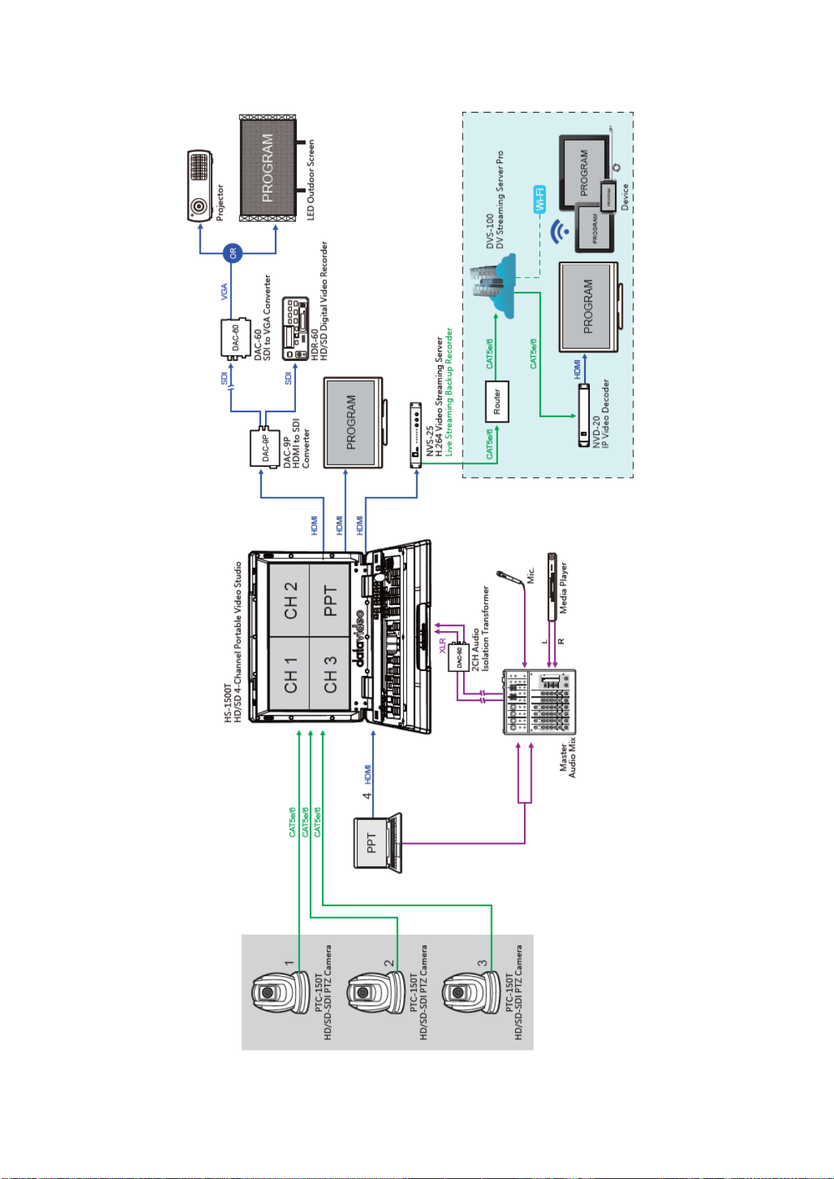
1.2 System Diagram
9
Page 10
Chapter 2 Connections and Controls
1
HDBaseT Port x 3
6
MIC IN – CH1/CH2
2
HDMI Video IN
7
Audio Input – Stereo RCA (Left/Right)
3
HDMI Video OUT x 3
8
DC IN
4
USB F/W Upgrade Port
9
Power Switch
5
TALLY Output Port
10
Stream Port
1. HDBaseT IN
The HDBaseT ports connect three HDBaseT cameras via
three CAT-6 Ethernet cables. The camera videos will be
displayed on the respective Multiview quadrants.
Note: The HDBaseT port is a specially designed port with
an outer fastening ring allowing the user to secure the
Ethernet cable connection. In the product package, three
Ethernet cable connectors are provided for the user to
customize your cable connection in your application
environment.
2. HDMI Video Input
The HDMI Video Input port connects an additional video
source device and the video will be displayed on the fourth
quadrant.
1
3
4
5
6 9 2
7
2.1 Rear Panel
10
Page 11
3. HDMI Video Output 1 – 3
Connect to a monitor for Program OUT display or other
HDMI destination devices.
4. USB F/W Upgrade Port
USB port for firmware upgrade. Please refer to the
Firmware Upgrade section for details.
5. TALLY Output Port
Sends Red and Green tally signals to each channel.
Red indicates On-Air, and Green indicates next camera
source. Tally output port can connect other Datavideo
peripheral devices such as ITC-100, ITC-200, AM-100 or
other monitor models, allowing the peripheral device to
communicate with the HS-1600T or send tally signal to be
displayed on the monitor.
6. Audio Input – XLR Balanced (CH1/CH2)
Two channels of XLR Balanced Audio Input.
7. Audio Input – Stereo RCA (Left/Right)
Connects unbalanced analog audio source (stereo).
8. Power Switch
Power switch ON/OFF
9. DC IN
DC in socket connects the supplied 48V / 190W PSU. The
connection can be secured by screwing the outer fastening
ring of the DC In plug to the socket.
11
Page 12
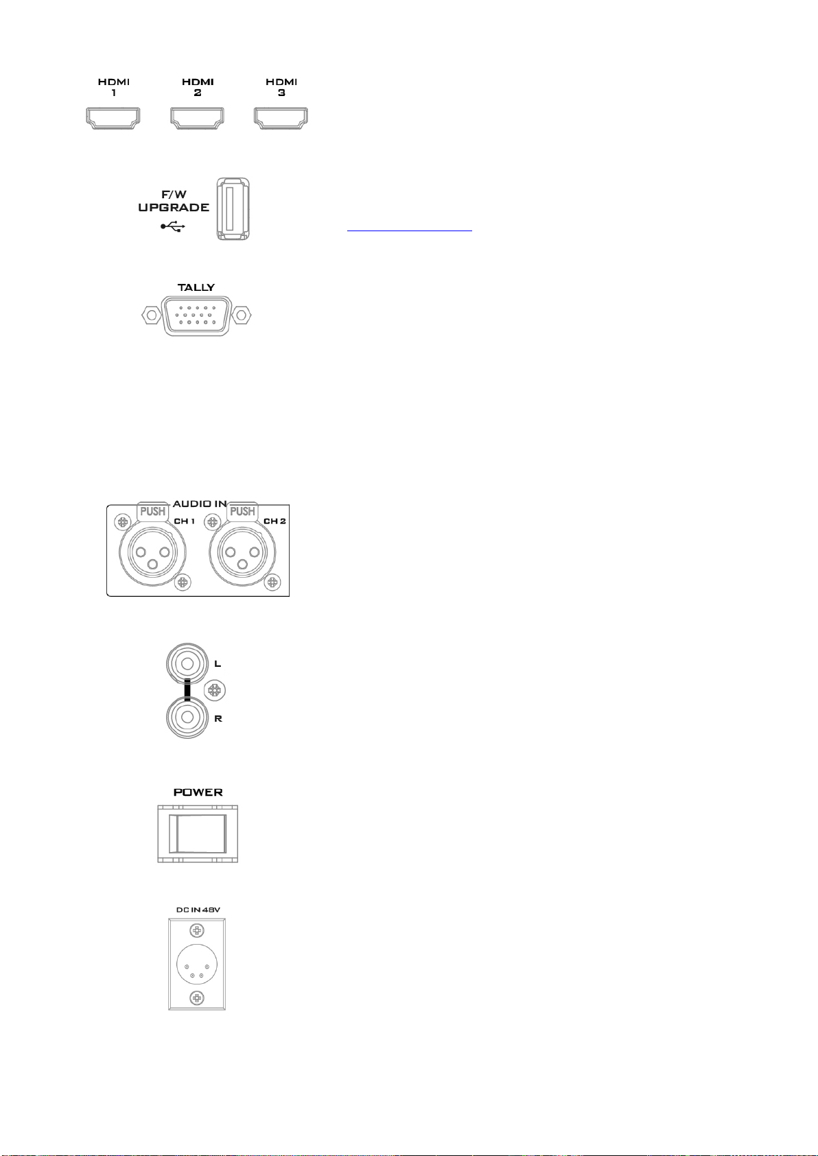
10. Stream Port
The stream port allows the user to establish direct
connection between the notebook computer and the HS1600T in order to access the built-in NVS-31 or connect the
NVS-31 to any local area network.
Note: See the chapter on Video Streaming for device
configuration.
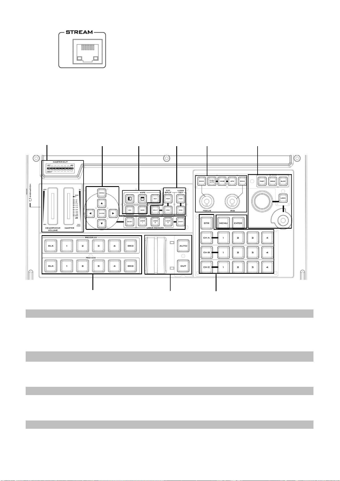
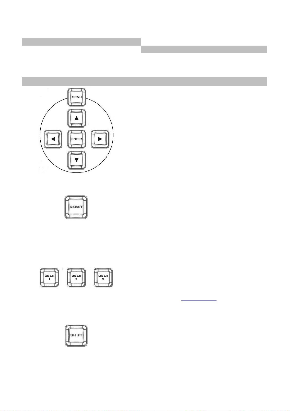
Switcher Settings
Volume Control
Menu browsing buttons
Volume adjustment sliders
RESET button
Headphone jack
User Memory
Audio meter
Shift button
Headphone volume control knob
Transition Effects
Camera Presets
WIPE transition effect selection
Channel Selection Buttons
MIX Enable/Disable button
Preset Buttons
WIPE transition effect Enable/Disable
STR Button
PIP/Keyer
FOCUS / IRIS / White Balance
Enable/Disable buttons for PIP Keyer
Focus Adjustment
Luma Keyer Enable/Disable buttons
IRIS Adjustment
Split Activation button
White Balance
Transition Control
PAN / TILT / ZOOM
T-Bar (manual transition)
Speed Selection Buttons
Volume
Control
Program/Preview
Transition Control
Switcher
Settings
PIP/Keyer
Transition
Effects
Camera Presets
Focus / IRS /
White Balance
PAN/TILT/ZOOM
2.2 Switcher Keyboard Panel
12
Page 13
CUT button
Joystick – PAN/TILT
AUTO transition button
VR Knob – ZOOM
Program/Preview
LOCK Button
Program row
Camera MENU Control
Preview row
MENU Button
ENTER Button
Switcher Settings
Menu browsing buttons
Press the MENU button to gain access to the menu;
use the up/down/left/right arrow buttons to browse
through the menu and press ENTER button to select an
option or MENU button again to exit.
Reset Button
Mode 1 – When in Menu Select mode (left hand
column of the OSD menu), pressing the 'Reset' button
will reset all current menu items to their factory
defaults.
Mode 2 – When in a Sub-Menu, pressing the 'Reset'
button will reset the current menu line only.
User Memory
User Memory buttons 1-3 allow the user to quickly
recall and load previously saved switcher settings with
a single button press. This includes PIP and Keyer
settings. See the User Memory section for more
information.
Shift Button
Pressing the Shift button will switch USER 1-3 buttons
to USER 4-6 buttons
13
Page 14
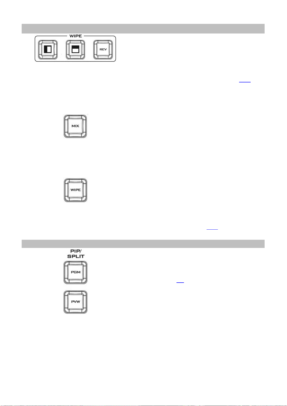
Transition Effects
WIPE Transition Effect Selection
Each Wipe button consists of black and white colors.
The white represents the current Program image and
the black represents the WIPE-IN image. The HS-1600T
provides 3 WIPE presets with the Horizontal and
Vertical WIPEs selectable on the control panel. The
Center WIPE can be selected from the menu (Start).
Pressing the REV button reverses the direction of the
WIPE.
MIX Enable/Disable Button
A MIX, also known as a dissolve, is a transition wherein
the Program video is replaced by the Preview video at
a smooth rate, and at the same time. Pressing the MIX
button enables the MIX transition effect and
automatically disables the WIPE button. To trigger the
MIX effect, simply press the AUTO button or move the
T-Bar.
WIPE Transition Effect Enable/Disable Button
Pressing the WIPE button enables the WIPE transition
effect after which the WIPE transition effect can be
selected. To trigger the WIPE transition effect, simply
press the AUTO button or move the T-Bar.
Wipe Transition Effect, Border and Position settings
can be found in the OSD menu (Start).
PIP / Keyer
Enable/Disable Buttons for PIP Keyer
Picture in Picture puts the selected Sub Video Source in
a window on the Main Program view, with control over
window size and placement. For PIP configuration,
please refer to the PIP section.
PIP PGM: Shows the configured PIP on the PGM
output after transition, however, the PIP cannot be
previewed on the QUAD split view display.
PIP PVW: Sets the configured PIP on the next
transition. Holding down this button allows selection
of the PIP source from the Preview Source row. The
selected source button will flash.
14
Page 15
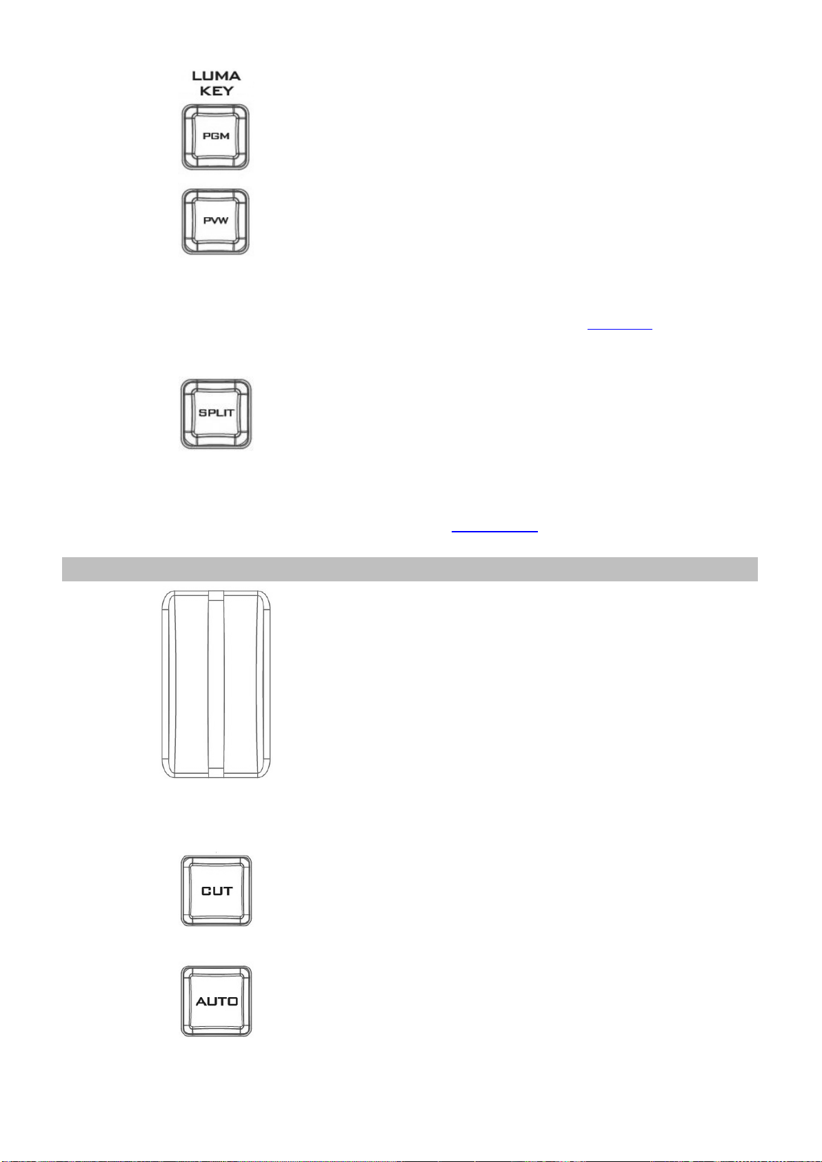
Luma Keyer Enable/Disable Buttons
Luma Key PGM: Shows the luma key source on the
PGM output and enables the luma key effect,
however, the luma key effect cannot be previewed on
the QUAD split view display.
Luma Key PVW: Enables luma key source for the PGM
output on the next transition. Holding down this
button allows selection of the luma key source from
the Preview Source row. The selected source button
will flash.
Please refer to Section 3.4, the Luma Key section, for
luma key configurations.
Split Activation Button
After activating the PIP window, pressing the Split
button will split the PROGRAM output display into two
with the program out view on the left and the PIP view
on the right.
To select the Split source, i.e. the program out view,
please see Section 3.2.5.
Transition Control
T-Bar (Manual Transition)
T-Bar is used for manual transition. The T-Bar can be
either all the way up, all the way down or anywhere in
between. When the T-Bar is pushed to halfway
between the topmost position and the bottommost
position, the keyboard functions will be disabled.
PVW and PGM views can be transitioned at your
preferred speed. To include the transition effect,
simply press the WIPE or MIX button, after which the
Transition Effect will be triggered as you move the TBar.
CUT Button
Pressing the Cut button performs immediate manual
switch between PVW and PGM views without the
transition effect.
AUTO Button
Pressing the Auto button automatically transitions
PVW and PGM views according to the selected speed
and the configured transition effect.
15
Page 16
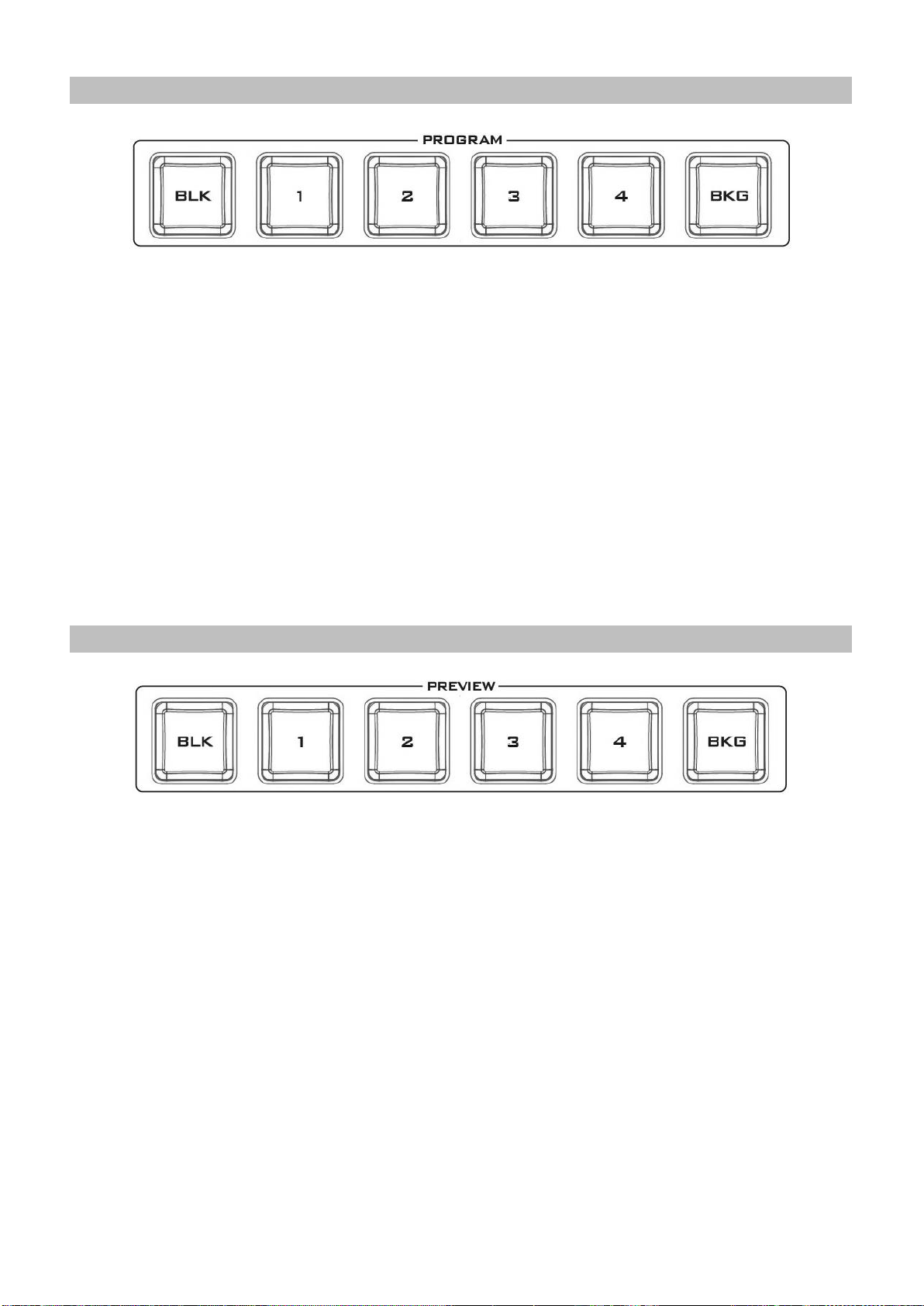
Program Output
Program Source Row
Pressing the number buttons along the PROGRAM row selects a video source for the PGM view.
BKG button: Pressing the BKG button will switch the background to a Matte background. The BKG
color can be configured on the OSD MENU and the available color options are listed as follows:
White
Yellow
Cyan
Green
Magenta
Red
Blue
Black
BLK button: Pressing the BLK button places a black screen on the PROGRAM view.
Preview Output
Preview Source Row
Pressing the number buttons along the PREVIEW row selects a video source.
BKG button: Pressing the BKG button will set the Preview OUT to a Matte background, which will be
displayed on the Program OUT monitor upon the next transition. The BKG color can be configured
on the OSD MENU and the available color options are listed as follows:
White
Yellow
Cyan
Green
Magenta
Red
Blue
Black
BLK button: Pressing the BLK button sets the Preview OUT to a black screen.
16
Page 17
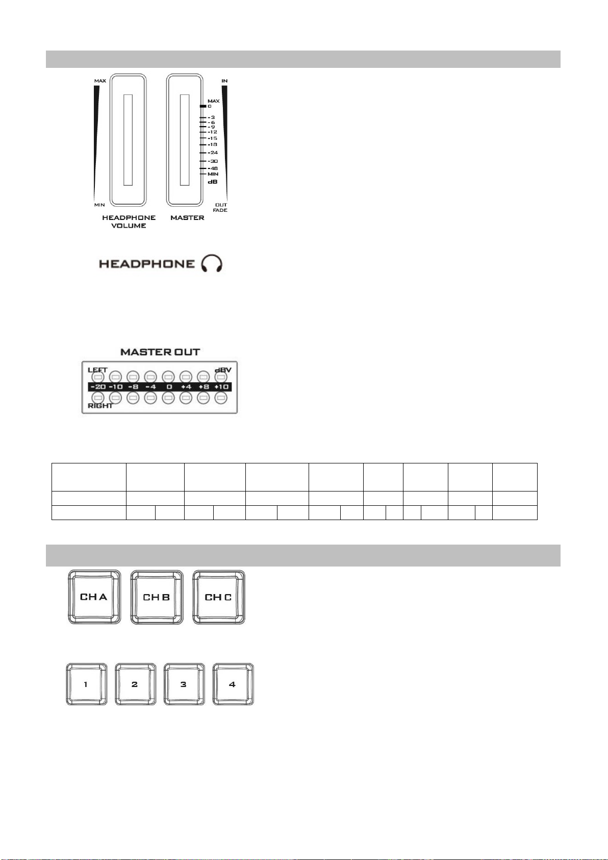
Volume Control
Volume Adjustment Sliders
Sliders to control audio levels for the Main audio
mixer.
Headphone Volume: Audio volume of the connected
headphone.
Master: Main audio output volume.
Headphone Jack
Headphone jack accepts the mini jack plug of the
stereo headphone type. The headphone volume is
controlled by the Headphone volume adjustment
slider.
MASTER OUT Meter
The LED style meters show the audio signal strength at
the Main Program Audio Output. The signal strength is
determined by the level set with the Master OUT
slider. The LEDs turn red at +10 dB to indicate clipping
distortion.
Audio
Volume (dBV)
-20
-10
-8
-4 0 +4
+8
+10
LED Color
G G G
G G Y Y R
Range (dBV)
-20
-12
-11
-9.5
-8.5
-6.5
-5.5
-3
-2 1 2
5.5
6.5 8 9+
G: Green Y: Yellow R: Red
Camera Presets
Channel Selection Buttons
To control or set up a connected camera, first select it
by pressing these buttons. The selected channel
button will be turned ON.
Preset Buttons
These buttons may be used to store up to four camera
positions for each camera. Each button corresponds to
one stored camera position. The button LED will be
turned ON when selected.
17
Page 18
STR Button
Pressing this button enters the HS-1600T into STORE
MODE. When activated, this allows the current camera
position to be stored in a chosen Channel Preset
Button. Press again to exit STORE MODE.
FOCUS / IRIS / White Balance
Focus Adjustment
To manually control the FOCUS setting, first press the
MANUAL button to enter the manual mode. The
button LED will be turned ON to indicate that the
manual mode is enabled.
The FOCUS dial can then be rotated to set the focus.
If the MANUAL button is disabled (OFF), the camera
will be in AUTO FOCUS mode.
IRIS Adjustment
To manually control the IRIS setting, first press the
MANUAL button to enter the manual mode. The
button LED will be turned ON to indicate that the
manual mode is enabled.
The IRIS dial can then be rotated to set the exposure.
If the MANUAL button is disabled (OFF), the camera
will be in AUTO IRIS mode.
White Balance
Push Auto
Push once to automatically adjust the camera white
balance setting.
MWB (Manual White Balance)
Push to enable manual white balance setting.
ATW (Force Automatic White Balance)
Push to enable automatic white balance setting.
PAN / TILT / ZOOM
Speed Selection Buttons
The speed at which the selected camera moves can be
chosen by pressing one of the three speed buttons.
18
Page 19
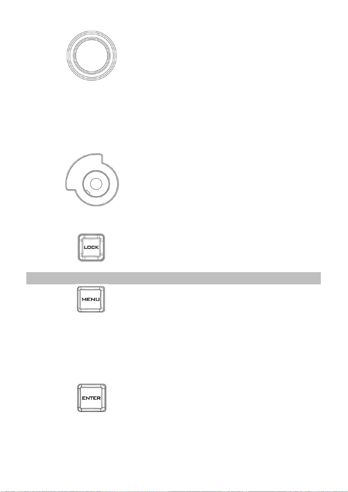
Joystick – PAN / TILT
PAN – Move the joystick left or right to pan the
selected PTZ camera from left to right or vice versa.
TILT – Move the joystick up or down to tilt the selected
PTZ camera up or down.
Note: Before attempting to use the joystick to PAN or
TILT a selected camera, first make sure the LOCK
button is not enabled. If the LOCK button LED is ON,
the joystick is locked; press the LOCK button to unlock
the joystick.
VR Knob – ZOOM
ZOOM – Twist the joystick clockwise (to the right) or
anti-clockwise (to the left) to have the selected PTZ
camera zoom in or out.
Note: Make sure the LOCK button is not enabled. If the
LOCK button LED is ON, the joystick is locked; press the
LOCK button to unlock the joystick.
LOCK Button
When enabled, the joystick will be in the lock state. To
resume its functional status, simply press the button
once to unlock the joystick.
Camera MENU Control
MENU Button
Press once to open the OSD MENU of the connected
PTC-150T on the monitor screen. Use the P/T joystick
to move between options. To select, simply press the
ENTER button. Please see the PTC-150T instruction
manual for details of the menu operation.
Note: Pressing the menu button again will not exit the
OSD MENU. Select the ESCAPE option on the OSD
MENU to exit.
ENTER Button
Press this button to select a menu option after the
camera OSD menu is opened.
19
Page 20

2.3 Monitor Control Panel
Power
Switches the HS-1600T Monitor Power ON / OFF
BLUE
Press this button to eliminate the red and green component of input
signals. Only the blue component of an input is displayed on the
screen. This allows adjustments of chroma and phase. (Phase
adjustment is effective with NTSC signals).
PTN
When pressed displays internally generated SMPTE 75% Colour Bars.
Press again to return to the previously selected video input.
ZOOM
This feature is designed for use with HD-SDI and HDMI sources above
720p resolution. Press this button to zoom in to the video on the
display. This is strictly a zooming function and does not alter the
native aspect ratio of the source pixels to fill the screen.
The ZOOM button allows you to toggle the Pixel Zoom feature
between zoom x1, x2, x4 and x8.
Menu Navigation Buttons
Display and navigate the setup menus. See Monitor Menu Options for
more details.
20
Page 21
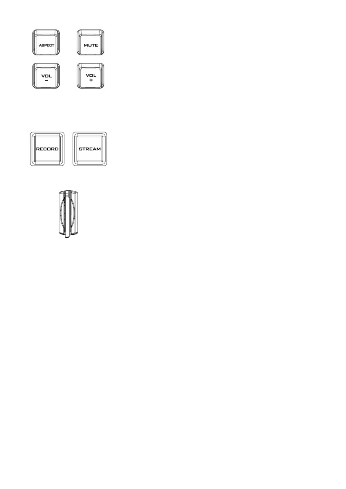
Aspect Ratio Button
Sets the Aspect Ratio to 16:9 / 4:3
Volume Control
Adjusts the speaker / headphone volume up / down.
MUTE
Mutes the audio from the internal speakers or headphone socket.
2.4 Streaming Control Panel
RECORD Button
Press RECORD button to start recording.
STREAM Button
Press STREAM button to start streaming.
SD Card Slot
Insert the SD card to the slot for recording.
Note: During recording, please do not remove the SD card as it may
cause file corruption.
21
Page 22

Chapter 3 Switcher OSD Menu
Option
Parameters
Parameter Value or Range
Default Value
Start
Transition Type
MIX
WIPE
Mix
Transition Speed
1-200 frames
60 frames; the duration
in second depends on
the Program OUT
resolution.
WIPE Effect
1. Horizontal
2. Vertical
3. Center
1
WIPE Border Size
OFF
Small
Middle
Large
Small
WIPE Border Color
White
Yellow
Cyan
Green
Magenta
Red
Blue
Black
Red
BKG Color
White
Yellow
Cyan
Green
Magenta
Red
Blue
Black
White
The switcher’s OSD menu allows the user to perform several configurations of video effects, such as
picture-in-picture, luma key and etc. The user can also configure the audio settings in the Audio
option. In addition, in the setup option, the user is allowed to set video output resolution, reset to
factory default, and selects the interface language.
3.1 Start
3.1.1 Transition Type
The HS-1600T provides two types of transition effect, which are cross dissolve (MIX) and WIPE. The
default setting is MIX.
3.1.2 Transition Speed
The Transition Speed allows the user to set the MIX or WIPE effect duration, in frames. If the
Transition Speed is set to a value of 60 then the transition will take effect over a period of 1 second if
the progressive video is chosen and 2 seconds if the interlaced video is chosen. When the AUTO
button is pressed, the transition will take the current Transition Speed defined by the user.
22
Page 23

Note: Pressing the left or right arrow button on the control panel allows the user to either
Option
Parameters
Parameter Value or Range
Default Value
PIP/Split
PIP Source
Black
Input 2
decrement or increment Position X by 1. To change the parameter value at an accelerated rate,
simply press and hold the left or right arrow button.
3.1.3 Wipe Effect
On the HS-1600T, there are three wipe effects available for the user to choose. The three wipe effects
are HORIZONTAL, VERTICAL and CENTER. The default is Horizontal.
3.1.4 WIPE Border Size
The WIPE Border Size generally allows the user to select an appropriate border width. Setting the
WIPE Border Size to OFF turns the border off. Setting this parameter to small selects a thin border;
middle will yield a medium size width; large is the maximum wipe border width.
3.1.5 WIPE Border Color
In this option, you will be allowed to select a color for your wipe border. The available colors are listed
as follows:
White
Yellow
Cyan
Green
Magenta
Red
Blue
Black
3.1.6 BKG Color
In this option, you will be allowed to assign a color to the BKG button. The available colors are listed
as follows:
White
Yellow
Cyan
Green
Magenta
Red
Blue
Black
3.2 PIP / Split
Picture-In-Picture (P-In-P) places a sub window on the PGM or Multiview screen. This option
(PIP/Split) allows you to configure various parameters of the PIP window.
Note: When PIP and Lumakey features are enabled at the same time, the lumakey source will be
the upper layer and the PIP source will be the lower layer. The layer order cannot be changed.
23
Page 24

Input 1
Input 2
Input 3
Input 4*
Background
Color Bar
PIP Size
1-100%
30%
Position X
-50% - +50%
20%
Position Y
-50% - +50%
10%
Split Source
Black
Input 1
Input 2
Input 3
Input 4*
Background
Color Bar
Input 2
Border Size
OFF
Small
Middle
Large
Small
Border Color
White
Yellow
Cyan
Green
Magenta
Red
Blue
Black
Red
3.2.1 PIP Source
In this option, the user will be allowed to assign the PIP source; the available sources are listed as
follows:
Tip: To quickly assign the PIP source, simply press and hold the PIP PGM button and then select a
source from the Program BUS.
3.2.2 PIP Size (PIP Window Size)
The PIP Size parameter ranges from 1 to 100 with 1% being the smallest and 100 being the largest.
Therefore 50% would represent a PIP window which is half the size of the background image. 100%
would see the PIP window totally cover the background image unless offset to one side.
Black
Input 1
Input 2
Input 3
Input 4*
Background
Color Bar
24
Page 25

3.2.3 Position X
Adjusting Position X parameter moves the PIP window horizontally. Pressing the left or right arrow
button on the control panel allows the user to either decrement or increment Position X by 1. To
change the parameter value at an accelerated rate, simply press and hold the left or right arrow
button.
3.2.4 Position Y
Adjusting Position Y parameter moves the PIP window vertically. Pressing the up or down arrow
button allows the user to either increment or decrement Position Y by 10. Press and hold the up and
down arrow buttons to change the parameter value at an accelerated rate.
3.2.5 Split Source
After the PIP window is activated, pressing the Split button will split the PROGRAM output display
into two with the program out view on the left and the PIP view on the right. The Split source, i.e. the
program out view, can be selected in this option. The available split sources are listed as follows:
Black
Input 1
Input 2
Input 3
Input 4*
Background
Color Bar
3.2.6 Border Size
The Border Size generally allows the user to select an appropriate PIP border width. Setting the
Border Size to OFF turns the PIP border off. Setting this parameter to small selects a thin border;
middle will yield a medium size width; large is the maximum PIP border width.
3.2.7 Border Color
The user is allowed to assign a PIP border color. The available colors are listed as follows:
White
Yellow
Cyan
Green
Magenta
Red
Blue
Black
*Note: Select Input 4 if you would like to use the video source connected to the HDMI input.
3.3 PIP Crop
The PIP Crop basically adjusts the PIP window borders. You can adjust each side individually (Left /
Right / Top / Bottom) or all four sides at the same time (Size).
25
Page 26

Option
Parameters
Parameter Value or Range
Default Value
PIP Crop
Size
0 – 100%
0
Left
0 – 100%
0
Right
0 – 100%
0
Top
0 – 100%
0
Bottom
0 – 100%
0
The effects of all parameters are described below:
Option
Parameters
Parameter Value or Range
Default Value
Lumakey
Lumakey Source
Black
Input 1
Input 2
Input 3
Input 4*
Background
Color Bar
Input 2
Mode
Black
White
Black
Cleanup Level
0 – 100
20
Transparency
0 – 64
64
Left – Adjusts the position of the left edge of the PIP window.
Right – Adjusts the position of the right edge of the PIP window.
Size – Adjusts the PIP image crop size.
Top – Adjusts the position of the top edge of the PIP window.
Bot – Adjusts the position of the bottom edge of the PIP window.
3.4 Lumakey
Keyer of the HS-1600T provides the user with the capability of luma keying.
Note: When PIP and Lumakey features are enabled at the same time, the lumakey source will be
the upper layer and the PIP source will be the lower layer. The layer order cannot be changed.
3.4.1 Lumakey Source
Lumakey source is where you can select the image for luma keying. The available sources are listed as
follows:
Black
Input 1
Input 2
Input 3
Input 4*
Background
Color Bar
26
Page 27

3.4.2 Mode
Option
Parameters
Parameter Value or Range
Default Value
Audio
Mute
OFF/ON
Off
HDMI Input
Input 1-4 / Follow
Follow
HDMI Group
Channel 1/2
Channel 3/4
Channel 5/6
Channel 7/8
Channel 1/2
Level
Auto / SMPTE / EBU
Auto
Tally Mode
Normal / Audio Mixer
Normal
There are two modes available on the Luma Keyer. Select Black if the image is on a black background
and white if the image is on a white background.
3.4.3 Cleanup Level
The Cleanup Level allows the user to fine tune the effect of the luma key. The default value is 20.
3.4.4 Transparency
In this option, you will be able to adjust the transparency of the overall foreground key image.
*Note: Select Input 4 if you would like to use the video source connected to the HDMI input.
3.5 Audio
This option allows the user to configure various audio settings such as muting HDMI output audio, set
the audio type, selecting your tally type and etc.
3.5.1 Mute
The Mute allows you to turn ON/OFF the embedded audio component at the HDMI-in. The default is
OFF.
3.5.2 HDMI Input
In this option, you can select the audio source. Selection of input 1-4 allows the HS-1600T to play the
enabled audio source. If “Follow” is selected, the audio will enter Audio follow Video mode, i.e.
playback of the audio of the output video.
3.5.3 HDMI Group
The HDMI Group allows the user to assign the HDMI audio channel. The default audio channel is
Channel 1/2. Any audio channel pair of the four audio channel pairs can be selected.
3.5.4 Level
There are two different audio standards available for selection. The user can either select the EBU or
SMPTE standard. By selecting AUTO allows the device to automatically detect the audio standard.
When the image is 50 Hz, the audio follows EBU standard and when the image is 59.94/60 Hz, the
audio follows SMPTE standard.
27
Page 28

3.5.5 Tally Mode
Option
Parameters
Parameter Value or Range
Default Value
User Mems
Load Memory
User 1-6
Load
Save Memory
User 1-6
Save
Option
Parameters
Parameter Value or Range
Default Value
Setup
PGM Out Res.
1080p/60
1080p/59.94
1080p/50
Tally output port generally sends two tally signals to each channel. In Datavideo products, Red
indicates On-Air, and Green indicates next camera source.
The HS-1600T provides two tally modes:
Normal: If in normal mode, tally lights of all camera sources displayed on the PGM monitor will be
turned ON (Red). These sources include PGM, PIP and Key sources. While transition is in progress, the
next video will be seen on the PGM monitor, tally light of the PVW source camera will thus also be
turned ON (Red).
Audio Mixer: If Audio Mixer mode is selected, tally light of the PGM source camera selected on the
keyboard panel will be turned ON (Red). While transition is in progress, the tally light color will remain
unchanged. The tally light color will only change (red/green) after the transition of PGM and PVW
views is complete.
3.6 User Mems
In “User Mems”, the user is allowed to load previously saved settings and save the currently
configured settings.
3.6.1 Load Memory
Use the up/down arrow to select the desired memory location and load the saved setting by selecting
“Load”.
Tip: The user can also press one of the USER memory shortcut buttons (1-3) on the control panel as a
quick way of loading those previously saved User configurations. Use the SHIFT button to switch
between USER MEMORY 1-3 and USER MEMORY 4-6.
3.6.2 Save Memory
Use the up/down arrow to select the desired memory location and save the current setting by
selecting “Save”.
3.7 Setup
In the “Setup” menu, the user can change the output resolution, reset the HS-1600T to its Factory
Default values, choose the preferred OSD menu language, upgrade firmware and view the current
firmware versions (Mainboard and Keyboard).
28
Page 29

1080i/60
1080i/59.94
1080i/50
720p/60
720p/59.94
720p/50
576i
480i
MV Out Res.
1080p/60
1080p/59.94
1080p/50
1080i/60
1080i/59.94
1080i/50
720p/60
720p/59.94
720p/50
Save Setup
[Save]
Factory Default
[Reset]
Language
English
Simplified Chinese
Traditional Chinese
MB Software
Version
KBD Software
Version
3.7.1 PGM Out Res.
In PGM Out RES., the user is allowed to select an appropriate PROGRAM output resolution. The
available resolutions are listed as follows:
1080p/60
1080p/59.94
1080p/50
1080i/60
1080i/59.94
1080i/50
720p/60
720p/59.94
720p/50
576i
480i
Once done, simply go to “Save Setup” to confirm the selected output resolution.
Note: Please make sure the output resolution is same as the input resolution to prevent unexpected
issues.
3.7.2 MV Out Res.
In MV Out RES., the user is allowed to select an appropriate MULTIVIEW output resolution. The
available resolutions are listed as follows:
29
Page 30

1080p/60
Option
Sub-options
Parameters
Parameter Value
or Range
Camera
Camera CH. Setup
Yes/No
[PTC-150T-01/02/03]
Camera Info
Camera Name
Vendor ID
MB Version
FPGA Version
Motor Version
Video
Video Format
1080i/60
1080i/50
1080p/29.97
1080p/25
720p/59.94
1080p/59.94
1080p/50
1080i/60
1080i/59.94
1080i/50
720p/60
720p/59.94
720p/50
Once done, simply go to “Save Setup” to confirm the selected output resolution.
Note: The new resolution will be effective once selected. If you have selected a resolution that is
not supported by the monitor, you will not be able to view the OSD menu. In this case, please
reboot your machine to restore the default resolution previously configured in the “Save Setup”
option.
3.7.3 Save Setup
In this option, select “Save” to save the current configuration.
3.7.4 Factory Default
Reset: Once selected, the factory default settings will be restored. The device will start the factory
reset process in 2 to 3 seconds after “Reset” is selected.
3.7.5 Language
The available OSD menu languages are English, Traditional Chinese and Simplified Chinese.
3.7.6 MB and KBD Software
The MB and KBD software versions will be respectively displayed.
3.8 Camera
In the “Camera” menu, the user will be able to change the camera name, view camera information
and perform some basic camera settings. The basic camera settings include the video format, mirror
mode, PAN/TILT direction and etc.
30
Page 31

720p/50
1080p/59.94
1080p/50
Mirror Mode
Off
V
H
H+V
Joystick Pan
Normal
Reverse
Joystick Tilt
Normal
Reverse
Memory Speed
1-16
Operator
Power
On/Off
R-Gain
0-255
B-Gain
0-255
Tally LED
Off
Red
Green
3.8.1 Camera CH. Setup
By selecting this sub-option, you will be able to enable/disable the camera setup.
3.8.2 PTC-150T-01/02/03
The PTC-150T-01/02/03 options will allow you to configure basic settings of the respective cameras.
Camera Info
Selecting the “Camera Name” will open up a keyboard on which you will be able to rename the
selected camera. Other parameters right below are simply information display such as Vendor ID, MB
Version, FPGA Version, and Motor Version.
Video
In the “Video” sub-option, you will be able to configure the Video Format, Mirror Mode, Joystick
Direction and Joystick Speed.
The available resolutions in the Video Format parameter are listed as follows:
1080i/60
1080i/50
1080p/29.97
1080p/25
720p/59.94
720p/50
1080p/59.94
1080p/50
In “Mirror Mode”, there are three types of modes available:
V: Vertical mirroring
H: Horizontal mirroring
31
Page 32

H+V: Horizontal and Vertical mirroring
In Joystick Pan/Tilt, you can either select the normal PAN/TILT direction or reverse the PAN/TILT
direction. The PAN/TILT speed can be configured in Memory Speed, which ranges from 1-16.
Operator
The Operator sub-option offers the user basic camera operation functions. Parameters of this suboption are described below:
“Power” basically turns ON/OFF the selected camera.
R-Gain/B-Gain: The red and blue components can be adjusted, ranging from 0 to 255.
Tally LED: You can either turn the tally light off or enable the red or green tally light.
32
Page 33

Chapter 4 Monitor
Main Options
Sub Options
Parameters
Parameters
MAIN ADJUST
BRIGHTNESS
0~100
CONTRAST
0~100
SHARPNESS
0~100
SATURATION
0~100
TINT
0~100
BACKLIGHT
0~100
NR
HIGH / MID / LOW / OFF
DLC
ENABLE / DISABLE
VOLUME
0~100
EXIT
COLOR
6500
9300
7500
USER COLOR
RED
0~100
GREEN
0~100
BLUE
0~100
EXIT
SCAN SETTING
UNDER SCAN
Full Image
OVER SCAN
Cropped Image
INFORMATION
H. FREQUENCY
V. FREQUENCY
RESOLUTION
VER.
LANGUAGE
English [default]
Francis
Deutsch
Español
Italiano
Dutch
Português
Russian
EXIT
SPECIAL FUNCTION
OSD TIMOUT
5-120 SEC
The HS-1600T Monitor can be configured via an on screen menu. When the
MENU button is pressed the Main Menu list is displayed on the monitor.
This section covers the Menu options in the order that they appear on the
monitor. These settings may also appear in more detail elsewhere in this
instruction manual. Options may vary depending on the firmware version in
use.
Once the chosen setting has been confirmed with the ENTER button, it is
stored within the switcher’s non-volatile memory.
4.1 MENU Options
33
Page 34

FRAME RATIO
80 / 90 / 0FF
4:3 MARK LINE
ON / OFF
CENTRAL MARK
ON / OFF
CINEMA ZONE MARK
ON / OFF
AUDIO CHANNEL L*
AUDIO CHANNEL R*
EXIT
FACTORY RESET
EXIT
* Selectable on PGM only; external HDMI and MV are allowed on 1 and 2 ONLY.
4.1.1 MAIN ADJUST
After pressing the MENU button on the monitor control panel, the first menu option highlighted is the
MAIN ADJUST option.
Press ENTER to access the MAIN ADJUST Menu and the Brightness option will be highlighted.
To adjust the Brightness, press Enter again. Use the Up / Down buttons to change the value and then
press Enter to store the new value and return to the main menu.
To configure other settings such as Contrast, Saturation, Sharpness, TINT and etc, use the Up / Down
buttons to select the desired option. Follow the above procedure to set the new value.
4.1.2 COLOR
Press ENTER to access the COLOR menu and the first option will be highlighted.
Press ENTER to select the first color option.
Use the Up / Down buttons to navigate the available color options listed as follows.
7500
9300
6500
USER COLOR
4.1.3 Information
The System Information displays Horizontal Frequency, Vertical Frequency, Resolution and the
Firmware Version (Ver.) of the monitor.
Once selected, the information below will be displayed.
H. FREQUENCY: 33.7KHZ
V. FREQUENCY: 60.0HZ
RESOLUTION: 1920X1080I
VER.: 0.11
4.1.4 Special Function
In the Special Function, you will be able to configure OSD TIMEOUT, Frame Ratio, 4:3 MARK LINE,
Central Mark, Cinema Zone Mark and Audio Channel L & R.
Use the Up / Down buttons to navigate the available options listed as follows. Press ENTER to access a
particular option.
34
Page 35

OSD TIMEOUT
5-120 SEC
FRAME RATIO
90 / 80 / 0FF
4:3 MARK LINE
ON / OFF
CENTRAL MARK
ON / OFF
CINEMA ZONE MARK
ON / OFF
AUDIO CHANNEL L*
1/2/3/4
AUDIO CHANNEL R*
1/2/3/4
4.1.5 Factory Reset
The monitor menu offers a Factory Reset option, which will return all the monitor settings to the
factory defaults
To reset the monitor, press the MENU button and then use the UP / Down buttons to navigate to the
FACTORY RESET option. Press ENTER again to reset the monitor. After a few seconds, the monitor
settings will return to factory defaults.
4.2 Firmware Update Procedure (Monitor)
From time to time Datavideo may release new firmware to either add new features or to fix reported
bugs in the current HS-1600T Monitor firmware. Customers can update the firmware themselves if
they wish or they can contact their local dealer or reseller for assistance should they prefer this
method.
This section describes the firmware update process and it should take approximately 15 minutes total
time to complete. Once started the update process should not be interrupted in any way as this
could result in a non-responsive unit.
To update the HS-1600T Monitor, you will need:
The latest firmware update for the HS-1600T Monitor.
This firmware file can be obtained from your local Datavideo office or dealer.
USB 2.0 pen drive with a USB A connector.
How to update the firmware
1. Unzip / extract the supplied zipped archive or rar folder.
2. Wipe the contents of the USB 2.0 pen drive so it is empty.
3. Transfer / copy the unzipped / extracted file to the USB 2.0 pen drive; make sure the file name is
renamed to MSTFLASH.bin.
4. Plug the USB 2.0 pen drive into the USB 2.0 port labelled MONITOR F/W
UPGRADE on the front of the monitor button panel.
5. Reboot HS-1600T and the update will start automatically.
6. The HS-1600T Monitor will reboot itself at the end of the process.
Note: The USB port can also be used to power the connected USB LED light.
35
Page 36

Chapter 5 Applications
[MAIN MENU]
1:
CAMERA SET (NORMAL)
2:
MEMORY
3:
VIDEO OUTPUT
4:
REMOTE CONTROL
5:
SYSTEM
5.1 Placing a logo on the video using the lumakey function
The HS-1600T allows the user to place a logo on the video using the lumakey function. First of all,
create a 1920x1080 (16:9) logo against a black or white background on a laptop. Once the logo is
created, please follow the steps outlined as follows to insert the logo layer.
Note: If the logo is dark, choose a white background; if the logo consists primarily of bright colors,
choose a black background.
1. Connect the laptop to the switcher’s HDMI Input Port.
2. Press the MENU button to open the OSD Menu on the four-quadrant Multiview display.
3. In the Lumakey option, set the “Lumakey Source” to Input 4.
4. In this example, the logo is against a black background so Black Mode is chosen.
5. Set the “Cleanup Level” to 10 if the background is in total black.
6. “Transparency” is set to 64 if an opaque logo is desired. Opaque logo can be created by setting
the “Transparency” parameter to 64. Semi-transparency effect can be generated by setting
the “Transparency” parameter to a value between 0 and 64.
7. Exit the menu after the Logo is properly configured.
8. Press the Luma Key PGM button to place the logo on the Program screen or the Luma Key
PVW button to place the logo on the Preview screen.
5.2 Connecting PTC-150T Cameras
DVIP is a communication interface that allows the user to control multiple PTC-150T cameras
remotely. Follow the steps outlined below to set up your PTC-150T cameras with the HS-1600T.
1. Locate the DIP switch at the bottom of the PTC-150T camera
2. Set DIP Switch positions 1 and 4 to ON
3. Power ON the PTC-150T PTZ Camera.
4. Open the main menu by pressing the MENU button on the HS-1600T’s keyboard panel and
select option 4 “Remote Control”.
36
Page 37

6:
CAMERA SET (ADVANCE)
7:
RESET P/T/Z
8:
ESCAPE
[REMOTE CONTROL]
1:
PAN/TILT REVERSE: P+T
2:
REMOTE SOURCE: DVIP, SW
3:
SET RS422
4:
SET DVIP
5:
SET IR
6:
PTZ INFO. OUTPUT: OFF
7:
ESCAPE
[SET DVIP]
1:
DVIP BAUDRATE: 115200
2:
ESCAPE
5. Select “SET DVIP” to configure the DVIP port
6. Set the DVIP baud to 115200
7. Connect the PTC-150T to the HS-1600T, which should automatically assign an IP to the PTC-
150T.
37
Page 38

Chapter 6 Video Streaming
The HS-1600T Portable Video Studio includes a built-in Video Streaming Server (NVS-31) allowing the
user to stream and record your program at the same time. From any SDI/HDMI input sources, the
Datavideo’s video streaming server generates an H.264 encoded stream that is compliant with RTSP
or RTMP protocols. While encoding the video at bit rates appropriate for live streaming, the
Datavideo NVS-31 concurrently records a high-quality MP4 file to an SD card.
Note: The built-in video streaming server and recording device are referred to as NVS-31.
6.1 Streaming Network Connection and Device Search
This section details how to connect the NVS-31 to a network with or without a DHCP server, and
describes how to acquire the NVS-31’s IP address.
Connecting to a DHCP Network (DHCP Mode)
Follow the following procedure to scan your DHCP network for connected NVS-31 devices.
Note: The NVS-31 will be automatically assigned an IP address upon connection to the DHCP
network.
1. Connect the NVS-31’s stream port to the network via an Ethernet cable.
2. Turn on the HS-1600T’s power and the NVS-31 will also be turned ON in the DHCP mode
by default.
3. Connect the laptop to the same network that the NVS-31 is connected to and download
the free IP Finder utility program.
4. Double click the IP Finder utility program icon to open the IP Finder interface.
5. Click the SCAN button to start searching for connected devices.
38
Page 39

Connecting to a NON-DHCP Network (Static IP)
Upon connection to a non-DHCP network, the NVS-31 will not be assigned of any IP addresses. As
such it is recommended that you manually assign a fixed IP address to the device or use the default IP
address (192.168.1.60).
Default Fixed IP
Default Fixed IP is primarily used in point-to-point connection, such as connecting the PC to the NVS31 directly. In a non-DHCP environment, the NVS-31 works in fixed IP mode only. To configure the
NVS-31 to the default IP, please follow the steps outlined below:
1. Connect the NVS-31’s stream port to the network via an Ethernet cable.
2. Turn on the HS-1600T’s power and the NVS-31 will also be turned ON in the DHCP
mode by default.
3. Search for the NVS-31 device according to the method as detailed in the previous DHCP section.
Once found, log into the user interface on the web browser.
4. Enter the system page by clicking the “System” tab
on the home of the user interface.
5. In the “Network Setting”, disable the DHCP mode.
6. You will then be allowed to manually enter the
static IP address once the DHCP mode is disabled. The static IP is 192.168.1.60 by default. The
subnet mask and default gateway are 255.255.255.0 and 192.168.1.254 respectively.
Tip: If you forget or lose the IP address, do the following to reset the network settings.
Turn off the switcher.
Press the RECORD and STREAM buttons at the same time then turn ON the power of the
switcher
Wait for about five seconds and release the button push as soon as you see the RECORD and
STREAM button LEDs light up.
The IP address should be the default IP which is 192.168.1.30.
Troubleshooting the Network Connection
Connect the NVS-31 to the network and open the IP Finder utility program. Scan for the device. If not
found, it is possible that your network is not assigning IP addresses. Reasons of this are outlined as
follows:
Router or DHCP server is not connected to the network.
New devices are blocked by the network administrator.
Anti-virus software or the firewall blocks the communication.
Solve the problem by attempting the following:
Turn off the router, wait for 10 seconds then turn on the router again.
Reset the NVS-31 to the factory default:
- Turn off the switcher.
- Push the Record and Stream buttons simultaneously while turning on the switcher’s power.
39
Page 40

- Wait for about five seconds and release the button push as soon as you see the RECORD
and STREAM button LEDs light up.
Reboot the PC.
If the problem still persists, try the following ways:
Temporarily shut down the anti-virus software or firewall.
Make sure no other devices are connected to the LAN (wired or wireless) because this may
result in IP conflicts.
After trying all methods and if the problem is still not solved, the NVS-31 video streaming server offers
the fixed IP feature that allows you to establish direct connection to the NVS-31. The default IP
address is 192.168.1.60.
This method allows you to configure the NVS device to the IP range of your network so that you do
not need a DHCP server to gain access to the NVS device.
Connect your PC to the NVS device directly using an Ethernet cable (not necessarily a crossover
cable).
Next, change the network settings of your PC or laptop.
Click START located at the bottom left corner of your screen.
On the text bar, enter Network Connections then click the icon that appears.
Double click the network adapter that connects your PC or laptop to the network.
Click the “Properties” button.
Select “Internet Protocol Version 4 (TCP/IPv4)” option and click the “Properties” button.
Check the “Obtain an IP address automatically” option.
Enter IPv4 settings:
- IP Address: 192.168.1.2
- Subnet Mask: 255.255.255.0 (System default is 255.255.255.0)
- Default Gateway: Not required for one-to-one connection.
40
Page 41

Note: Please write down the IPv4 address previously entered as it may be needed after you
are done with streaming or recording.
The NVS-31 should now be connected with an IP address of 192.168.1.60.
If the NVS-31 still cannot connect, simply restore the NVS-31 to the factory defaults.
- Turn off the switcher.
- Push the Record and Stream buttons simultaneously while turning on the switcher’s power.
- Wait for about five seconds and release the button push as soon as you see the RECORD
and STREAM button LEDs light up.
- Make sure no other devices are connected to the LAN (wired or wireless) because this may
result in IP conflicts.
Login the NVS-31 via a web browser.
- Default user name is admin
- Default password is 000000
Click the “System” tab then on the system page, enter network settings such as static IP and
default gateway. Make sure that the default gateway matches your connected network and no
device shares the same IP as the NVS-31.
For example, if your router’s default gateway IP is 10.10.1.1, then in the default gateway field,
you should also enter 10.10.1.1. Then set the IP address of the NVS-31 to 10.10.1.X, which can
range from 10.10.1.2 to 10.10.1.255. Pick an unused IP address.
DHCP:Disable
Static IP:X.X.X.Y;the first three decimal numbers must be the same as your router or switch.
The number Y must be a number not used by any devices connected to the network.
Subnet Mask:255.255.255.0
Default Gateway:Z.Z.Z.Z;same as the gateway IP of your router or switch.
41
Page 42

Note: Some router may require special gateway IP setting; instead of the standard
192.168.1.1. Therefore, you should check the network properties on the PC before switching
to the fixed IP mode.
For example, some routers have a gateway IP of 192.168.1.254 and as a result, the default
gateway and primary DNS fields on the NVS-31 must also be configured to 192.168.1.254.
Primary DNS: Same as the default gateway IP, which, if causing issues, can be changed to
8.8.8.8 or 8.8.8.4 (Public DNS provided by Google).
Click the “Submit” button to save the network settings.
Reconnect the PC and the NVS-31 to the network.
Restore the PC’s original network settings.
Shut down the HS-1600T; wait for approximately five seconds before turning the HS-1600T
back ON.
You should be able to access the NVS-31 through the fixed IP address.
Advanced Troubleshooting
If you still are unable to connect, please try the following:
Use the ARP table to search for the encoder’s MAC address; the device’s MAC address is on
the print label at the bottom of your HS switcher.
MAC address starts with 00:07:36:03:xx:xx.
- Switcher’s MAC address starts with 00:07:36:07:xx:xx (HS-1600T and HS-1600T only)
On the command prompt (terminal on MAC OS), enter "arp -a" then press enter key to display
an ARP list. See if the NVS-31 is successfully connected to the network.
Execute services.msc,and on the right column of the “Services” window, locate “DHCP Client”
then click “Restart”.
On the command prompt, enter ipconfig/flushdns followed by ipconfig/release and
ipconfig/renew.
6.2 Web User Interface
By now, we have obtained the IP addresses of the PC and the NVS-31. Enter the NVS-31’s IP address
into the address bar of a browser then hit the ENTER button. Login by entering the user name as well
as the password into a pop-up dialogue box as shown below.
Username: admin Password: 000000
42
Page 43

Click OK to login. Once logged in, the first page that appears will be the Status page.
Status
You will see the Status page immediately after logging into the NVS-31 web UI. On the Status page,
you will be able to view the Operation Mode, Video Resolution, Stream Settings, Record Settings,
Record Media and Messages.
Note: The NVS-31 web UI is not updated in real time so it is not synchronized with the device status.
43
Page 44

While monitoring streaming and recording, please update the page periodically even if you choose to
physically operate the device or a mixed physical and web UI operations. This ensures the page is
always displaying the most up-to-date information.
Operation Mode
Click the Operation Mode tab on the tool bar to open the operation mode configuration page.
The NVS-31 offers the following operation modes:
Record and Stream: Streaming and recording functions are enabled at the same time.
Stream Only: Only streaming mode is enabled.
Record Only: Only recording mode is enabled.
In each mode, the user will be allowed to customize various stream and record settings.
In the Stream Only mode, settings such as Resolution, Frame Rate, Profile, Video Bitrate (bps), Audio
Bitrate (bps), GOP and Stream Type can be configured.
44
Page 45

Six stream types are available on the NVS-31 and they are RTSP, RTMP, HLS, SRT, TS and Youtube. See
Section 5.3 for details.
Click the “Apply” button to apply the new stream settings. Click the “Start Stream” button to open
the stream and the “Stop Stream” button to end the stream.
As for recording, the settings are Resolution, Frame Rate, Profile, Video Bitrate (bps), Audio Bitrate
(bps), GOP, File Name and File Size.
45
Page 46

Click the “Apply” button to apply the new record settings. Click the “Start Record” button to start
recording and the “Stop Record” button to stop recording.
Every mode configuration page includes a profile drop-down menu from which the user is allowed to
access different profiles of pre-saved settings. These profiles are described in the following section.
Record & Stream Mode – Record and Stream Encoder Setting Profile
In the Record and Stream mode, the Record and
Stream Encoder Setting Profile drop-down menu
provides the user with four user profiles as shown in
the diagram below.
Note: If both record and stream use high bitrates, it
is recommended to use 1G router at the minimum
for quality issue.
46
Page 47

Stream Only Mode – Stream Encoder Setting Profile
Stream Encoder Settings
Resolution
The first step of encoder setup is to adjust the image size. It is best to
either match your original video source or scale it down. For example,
capture at HD 720 and stream at HD 720. Or capture at HD 720 and
stream at 540 (high).
You should never be scaling up and streaming at a higher resolution than
your original video source. For example, it does not make sense to
capture at 720 and stream at 1080. Note that you will also have no gain
in quality and you are using more bandwidth than is necessary for your
viewers.
You should also be aware that higher resolutions require greater
processing power to encode the stream. Attempting too high of a
resolution on too little processing power can result in degraded image
quality and corrupted or interrupted streams or recordings.
Record Only Mode – Record Encoder Setting Profile
The following profiles shown in the diagram are
available in the Stream Only mode.
If Record Only mode is selected, three profiles
shown in the diagram below will be readily
available for the user.
In addition, all three operation modes allow the
user to define custom settings (Customize 1/2/3).
For details of custom settings, see the section on
customizing your operation mode.
Stream and Record Settings
In the section, you will be introduced various setting options of stream and record functions.
47
Page 48

Frame Rate
Select a frame rate from the drop-down menu for video streaming. Note
that frame rates should always match the frame rate of the video source.
Auto Stream
If the Auto Stream is enabled, in the event of power outage, the stream
will be automatically restored after the switcher is powered ON again.
Profile
Profile sets the H.264 encoding profile for your stream. The available
options are Baseline, Main, and High. Typically, High profile provides the
best image quality and is suitable in most instances. However, depending
on the decoder used when viewing the stream, such as with mobiles
devices, a Main or Baseline profile may be required.
48
Page 49

Video Bitrate (bps)
The bitrate of the video specifies the amount of information stored in the
video. The higher the bitrate is, the clearer the video is. However, when
choosing your encoding settings for streaming, you should first check
your available upload bandwidth. A good rule of thumb is for the bitrate
of your stream to use no more than 50% of your available upload
bandwidth capacity on a DEDICATED line. For example, if the result you
get from a speed test shows that you have 2Mbps of upload speed
available, your combined audio and video bitrate should not exceed
1Mbps.
Usually high bitrate means good image quality; however, there are also
exceptions. For example, SD video may appear acceptable at 1000 Kbps
(1M) but HD video is unacceptable at 1000 Kbps. Therefore we
recommend the following settings for your video bitrate:
When NVS-31 is in record-only mode, the recommended video
bitrate is 16 Mbps.
When NVS-31 is in stream-only mode, the recommended video
bitrate is 10 Mbps.
When NVS-31 streams and records simultaneously, sum of the
stream and record video bitrates should not exceed 12Mbps.
Audio Bitrate (bps)
The NVS-31 offers the user the following audio bitrates at which you may
want to stream the audio. It is recommended to select 128Kbps or
higher.
49
Page 50

GOP
GOP pattern with longer GOP length encodes video very efficiently.
Shorter GOP lengths usually work better with video that has quick
movements, but they do not compress the data rate as much. Depending
on your applications, the NVS-31 offers the user 16 GOP sizes ranging
from 1 to 180.
Stream Settings
Stream Type
The NVS-31 offers the user six stream types. There are RTSP, RTMP, TS,
HLS, SRT and Youtube.
Please note that when streaming, the NVS-31 converts video into data,
which are sent across an IP network. High bitrates consume more
bandwidth across the IP network. In a gigabit office LAN, high bitrate may
not be a concern and Speed/Bandwidth is therefore not the limitation in
a NVS-31 application environment.
If your available bandwidth is limited, you should reduce both your
resolution and your bitrate accordingly. A good rule of thumb is for the
bitrate of your stream to use no more than 50% of your available upload
bandwidth capacity on a dedicated line. For example, if the result you get
from a speed test shows that you have 2Mbps of upload speed available,
your combined audio and video bitrate should not exceed 1Mbps.
Stream Type – RTSP
RTSP Port
RTSP Port is 554 by default.
50
Page 51

RTSP HTTP Port
RTSP HTTP port is 8000 by default.
Video Only
Enable this option if you just want to stream the video without the audio.
RTSP Username/Password
The account and password are root by default.
Stream Type – RTMP
RTMP URL
Enter the RTMP URL obtained from any live streaming
platform such as Ustream.
Stream Name
Enter the stream name or key from any live streaming
platform such as Ustream.
Account
Enter your RTMP account name.
Password
Enter the password of your RTMP account.
Audio Only
In this option, the user is allowed to choose to stream
Audio Only or Video Only. If disabled, video and audio
streams will be delivered simultaneously.
51
Page 52

Stream Type – TS
TS Port
The TS port number is 12345 by default.
TS IP
The TS IP address is 239.100.100.101 by default.
Video Only
Enable this option if you just want to stream the video
without the audio.
Stream Type – SRT
SRT Port
The SRT port is 9001 by default.
Play URL
A stream URL will be generated after the Start Stream
button is clicked.
Record Encoder Settings
Resolution
Recording resolution is the number of pixels (dots) used to create an
image. Higher resolutions use more pixels to create an image. This means
that greater amounts of detail can be expressed in the image, but larger
files sizes and a greater amount of storage (i.e. hard drive space) are
required to save the images or video.
52
Page 53

Frame Rate
Frame rate greatly impacts the style and viewing experience of a video.
Different frame rates yield different viewing experiences, and choosing a
frame rate often means choosing between things such as how realistic
you want your video to look, or whether or not you plan to use
techniques such as slow motion or motion blur effects.
Below is a list of common options for different applications:
24fps – This is the standard for movies and TV shows, and it was
determined to be the minimum speed needed to capture video while
still maintaining realistic motion.
30fps – Videos with a lot of motion, such as sports, will often benefit
from the extra frames per second.
60+fps – Anything higher than 30fps is mainly used to create slow
motion video or to record video game footage.
Profile
Profile sets the H.264 encoding profile for your recorder. The available
options are Baseline, Main, and High. Typically, High profile provides the
best image quality and is suitable in most instances.
Video Bitrate (bps)
The bitrate of the video specifies the amount of information stored in the
video. The higher the bitrate is, the clearer the video is.
Recommended video bitrate
720P or lower – 8 – 10 mbps
1080P or higher – 15 mbps or higher
53
Page 54

Audio Bitrate (bps)
The NVS-31 offers the user the following audio bitrates at which you may
want to record the audio. It is recommended to record at 128Kbps or
higher.
GOP
GOP pattern with longer GOP length encodes video very efficiently.
Shorter GOP lengths usually work better with video that has quick
movements, but they do not compress the data rate as much. Depending
on your applications, the NVS-31 offers the user 16 GOP sizes ranging
from 1 to 180.
Record Settings
File Name
Enter the name of the recording file.
File Size
Select the file size of a single recording file.
Recording File
Display the file that is currently being recorded.
54
Page 55

Note: The record function is activated after the Start Record button is clicked. The
Storage Device Information
Vendor
Display of the manufacturer’s information.
Product
Display of the name of the SD card.
Capacity
Display of the SD card’s total capacity and the remaining
capacity.
REC indicator will appear as shown on the left. Flashing indicates that the record
function is starting. A constant lit indicator means the record function has been
activated successfully (The indicator flashing three times then turned off indicates
errors). The activation time is approximately 2 to 3 seconds.
Storage
The web UI of the HS-1600T’s built-in video streaming server (NVS-31) also displays storage device
information, allowing the user to view the SD card status. The Status page of the web UI is shown in
the diagram below.
55
Page 56

Storage Format
Select a storage format before clicking to
format your SD card.
FAT32
EXFAT
NTFS
Storage Content
Display of the SD card content.
File name
Last Modified
Size
Type
CG
CG Settings
CG Enable/Disable
Select ON/OFF from this drop-down menu to
enable/disable the CG overlay function.
The CG function on the HS-1600T’s built-in video streaming server allows the user to place a textual
layer on top of the video. The CG settings on the CG page are shown in the diagram below.
56
Page 57

Text
Enter the text of the CG overlay.
Location-X
Enter the x-coordinate.
Location-Y
Enter the y-coordinate.
Background
You can either select a black background or none.
Text Size
Select the font size of your CG overlay text.
System
The system page of the HS-1600T’s built-in video streaming server allows the user to configure several
network and system related settings such as DHCP enable/disable, static IP address, subnet mask,
default gateway, primary and secondary DNS, and etc.
The system settings are HLS preview enable/disable, time settings, firmware update, device name,
and account login information.
The system page is shown in the diagram below.
57
Page 58

58
Page 59

Network Settings
DHCP IP Assignment
Select an option from this drop-down menu:
Enable (DNS AUTO)
Enable
Disable
Static IP Address
The static IP field will be activated for the user to
manually enter an IP address once the DHCP is disabled.
The static IP is 192.168.1.60 by default.
Tip: If you do not know the device’s IP address, you can
always use the following method to reset the network
settings.
Shut down the machine
Turn on the machine while holding down RECORD
and STREAM buttons simultaneously.
Approximately after 5 seconds, release the RECORD
and STREAM buttons as soon as the button LEDs are
turned ON.
Fixed IP address is 192.168.1.60 by default.
Subnet Mask
Static IP address mode requires subnet mask, which is
255.255.255.0 by default.
Default Gateway
Static IP address mode requires default gateway, which
is 192.168.1.254 by default.
Primary DNS (Optional)
Primary DNS is required in static IP mode only but
optional.
Secondary DNS (Optional)
Secondary DNS is required in static IP mode only but
optional.
59
Page 60

MAC Address
Display of NVS-31’s MAC address.
Submit Button
After the network settings are configured, click the
Submit button to save the new settings.
HLS Preview
Here you will be able to enable/disable HLS preview.
Click the Submit button to save the new settings.
Time Setting
Type
In this drop-down menu, you can either select to allow
the device to retrieve the time automatically from the
Network Time Protocol (NTP) server or manually select a
time zone from the Time Zone drop-down menu.
Time Zone
Click the drop-down menu to select a time zone for your
device.
60
Page 61

Date/Time
Date and Time fields show the device’s system date and
time values.
Click the Submit button to save the new settings.
Firmware Update
NVS-31 Firmware Update
Click the Browse button to search for the latest
firmware file saved on the PC’s hard disk. Click the
Update button after the latest firmware file is uploaded.
Device Name Setting
Device Name Setting
Enter a name for this device and click the Submit button
to write this name into the device.
Account Setup
Account Setup
Enter the NVS-31’s account name and password. Click
the Apply button to save the new settings.
System Control
Restore to Default
Click this button to restore default settings.
System Reboot
Click this button to reboot the NVS-31.
61
Page 62

6.3 Operations
In this section, we will discuss how to customize your operation mode, how you can play the video via
different streaming protocols and how to place texts on your video.
Custom Operation Mode
The HS-1600T’s built-in video streaming server allows the user to customize operation mode settings
(Record and Stream/Stream Only/Record Only). Follow the steps outlined below to configure your
device.
1. Select an operation mode.
2. Click the “Record and Stream Encoder Setting Profile” drop-down menu and select “Customise 1”.
3. Customize settings such as resolution, frame rate, profile, video bitrate (bps), audio bitrate (bps)
and GOP. Click the Apply button to save these settings in Customise 1.
Note: Follow the above steps to customize Stream Only and Record Only modes. After customise
1/2/3 are configured, to apply settings saved in these profiles, simply click the drop-down menu
then select the profile that you would like to use. Lastly, click the Apply button to load the profile
settings to the device.
Video Streaming
The NVS-31 provides the user with different options for video streaming such as RTSP, TS, RTMP, HLS,
SRT and Youtube.
This section discusses settings of these options and how to stream your video using these methods.
62
Page 63

RTSP/TS/HLS/SRT
In the RTSP/TS/HLS/SRT modes, the NVS-31 is a stream server which allows any client device to
connect and playback your video stream. However, if you would like to stream to multiple client
devices, we recommend using a separate media server to set up your streaming environment.
The following operation procedure uses VLC media player to playback video stream. If your
PC or laptop does not have VLC media player installed, please visit VideoLAN’s official
homepage (https://www.videolan.org/) and download the installation file then install the
program.
Please follow the steps below to obtain the RTSP URL:
1. Open the stream settings page
2. Select RTSP
3. Click the Start Stream button to generate the RTSP URL.
4. Based on your settings, the device will automatically generate the RTSP URL.
5. Before streaming the video via RTSP, enter the RTSP URL into the client device.
6. Open VLC then click Open Network Stream (shown in the diagram below).
7. As shown in the diagram below, enter the stream URL then click Play to start streaming.
63
Page 64

Please follow the steps below to obtain the TS URL:
1. Open the stream settings page
2. Select TS.
3. Enter the TS port number which is 12345 by default.
4. In the TS IP field, enter your PC’s IP address such as 192.168.100.100.
5. Click the Start Stream button to generate the TS URL which, in this example, will be
udp://192.168.100.100:12345.
6. Before streaming the video via TS, enter the TS URL into the client device.
7. Open VLC then click Open Network Stream (shown in the diagram below).
64
Page 65

8. As shown in the diagram below, enter the stream URL then click Play to start streaming.
Please follow the steps below to obtain the HLS URL:
1. Open the stream settings page
2. Select HLS
3. Click the Start Stream button to generate the HLS URL.
65
Page 66

4. Based on your settings, the device will automatically generate a .m3u8 stream URL as shown
below.
5. Before streaming the video via HLS, enter the HLS URL into the client device.
6. Open VLC then click Open Network Stream (shown in the diagram below).
7. As shown in the diagram below, enter the stream URL then click Play to start streaming.
8. You can also play .m3u8 stream URL using the devices listed as follows:
iPhone, iPad and MacBook: Use Safari to open the .m3u8 stream URL.
Windows 10: Use Microsoft Edge to open the .m3u8 stream URL.
66
Page 67

Please follow the steps below to obtain the SRT URL:
1. Open the stream settings page
2. Select SRT and the SRT port number is 9001 by default.
3. Click the Start Stream button to generate the SRT URL.
4. Before streaming the video via SRT, enter the SRT URL into the client device.
5. Open VLC then click Open Network Stream (shown in the diagram below).
6. As shown in the diagram below, enter the stream URL then click Play to start streaming.
67
Page 68

RTMP
In RTMP mode, the NVS-31 can only send one data stream to one CDN or media server that supports
the Real-Time Messaging Protocol (RTMP). Examples of the RTMP media server are USTREAM and
Youtube.
In the following section, we will show you how to set up an RTMP stream to Youtube. The step-bystep account setup is outlined as follows:
1. First of all, you have to obtain Server URL and Stream name/key from Youtube.
2. Open the Youtube Live Dashboard https://www.youtube.com/live_dashboard
3. On the left column, locate and click “Stream now.”
68
Page 69

4. On the right, scroll down to the bottom where you will be able to find Server URL and Stream
name/key.
5. On the NVS-31, open the Stream Only operation mode page.
6. Select RTMP from the Stream Type drop-down menu.
7. Enter the Server URL obtained from the Youtube Live Streaming page into the RTMP URL field.
8. Enter the Stream name/key obtained from the Youtube Live Streaming page into the
StreamName field.
9. As required by the live streaming channel, enter your Youtube account name and password into
the Account and Password fields.
10. Click the Start Stream button to start streaming the live video on the Youtube Live Streaming
page. You should also see an RTMP URL generated.
11. The RTMP URL is another alternative that allows you to view the live stream on a web browser.
Enter the RTMP URL into the web browser’s address bar then hit the Enter button to open the live
video stream.
12. Click the Stop Stream button to stop live streaming.
Tip: You are allowed to stream audio or video only.
69
Page 70

Youtube
The HS-1600T’s built-in video streaming server provides the user with the capability of streaming to
Youtube directly. The step-by-step account setup is outlined as follows:
1. See section 6.1 for instructions on connecting the NVS-31 to the network. Once connected, search
for the NVS-31 on your PC or laptop.
2. On the PC or laptop, enter the NVS-31’s IP address into the address bar of the web browser.
3. Login the NVS-31 web interface then click the Operation Mode tab.
4. Select “Stream Only” mode.
5. Configure the following menu options:
Resolution
Frame Rate
Profile
Video Bitrate (bps)
Audio Bitrate (bps)
GOP
Stream Type
6. Select Youtube from the Stream Type drop-down menu.
7. Click the “Start Stream” button.
8. The loading page appears.
9. On the pop-up window, enter the User Code.
70
Page 71

10. Enter the User Code then click Next.
71
Page 72

11. Select your account.
12. Click the Allow button to grant the encoder access to the Youtube account.
13. After the Allow button is clicked, you will be prompted that the device has been connected
successfully.
72
Page 73

14. At last, login your Youtube account from the web browser to view the live video stream.
Change to different Youtube account for live streaming
The HS-1600T’s built-in video streaming server allows the user to perform live streaming using
different Youtube accounts. The step-by-step account setup is outlined as follows:
1. See section 6.1 for instructions on connecting the NVS-31 to the network. Once connected, search
for the NVS-31 on your PC or laptop.
2. On the PC or laptop, enter the NVS-31’s IP address into the address bar of the web browser.
3. Login the NVS-31 web interface then click the Operation Mode tab.
4. Select “Stream Only” mode.
5. Configure the following menu options:
Resolution
Frame Rate
Profile
Video Bitrate (bps)
Audio Bitrate (bps)
GOP
Stream Type
6. Select Youtube from the Stream Type drop-down menu then click the Change Account button.
73
Page 74

7. Click the Start Stream button.
8. A pop-up window will appear, prompting the user to enter User Code.
9. Click the Next button after the User Code is entered.
74
Page 75

10. Select “Use another account.”
11. Enter the new account name then click the Next button.
75
Page 76

12. Enter the password then click the Next button to switch to another account for live video
streaming on Youtube.
Text Overlay Video
The HS-1600T’s built-in video streaming server not only allows you to stream and record your
program, it also features a CG tool that is capable of overlaying text on the video currently being
broadcast.
The CG settings page is shown below:
76
Page 77

Follow the steps below to overlay text on the video:
RECORD Button
STREAM Button
Solid White
Record function in idle state
Stream function in idle state
Blinking Red
Record function is activating or resetting
Stream function is activating or
resetting
Solid Red
Record function activated
Stream function activated
1. Open the CG settings page.
2. Enable the CG function.
3. In the Text field, enter the overlay text.
4. Enter the X and Y coordinates to set the text position.
5. Click the Apply button to save the new settings.
Note: Increasing the X coordinate moves the overlay text to the right and decreasing the X
coordinate moves the overlay text to the left; increasing the Y coordinate moves the overlay text up
and decreasing the Y coordinate moves the overlay text down.
6.4 Stream and Record Buttons
The RECORD and STREAM buttons on the front panel of the HS-1600T
give the user certain controls of the record and stream functions. In
this section, we will cover operations of these two buttons in detail.
Button LED behaviors and their corresponding states are listed in the
table below:
77
Page 78

Record Button
Start recording
When idle, the RECORD button is solid white.
Press and hold the RECORD button for approximately 1 second.
When the record function is activating, the RECORD button turns from solid white, then
blinking red and finally to solid red.
When the RECORD button is solid red, this indicates that the record function has been
successfully activated.
Note: The RECORD button is disabled in the Stream Only mode.
Stop recording
While recording, the RECORD button is solid red.
Press and hold the RECORD button for approximately 1 second.
When the record function is terminating, the RECORD button turns from solid red, then
blinking red and finally to solid white.
When the RECORD button is solid white, this indicates that the record function has been
successfully terminated.
Stream Button
Start streaming
When idle, the STREAM button is solid white.
Press and hold the STREAM button for approximately 1 second.
When the stream function is activating, the STREAM button turns from solid white, then
blinking red and finally to solid red.
When the STREAM button is solid red, this indicates that the record function has been
successfully activated.
Note: The STREAM button is disabled in the Record Only mode.
Stop streaming
While streaming, the STREAM button is solid red.
Press and hold the STREAM button for approximately 1 second.
When the stream function is terminating, the STREAM button turns from solid red, then
blinking red and finally to solid white.
When the STREAM button is solid white, this indicates that the stream function has been
successfully terminated.
Operation Mode
Checking the NVS-31’s operation mode
First make sure the stream and record functions are in idle state, i.e. STREAM and RECORD
buttons are solid white.
78
Page 79

Press RECORD or STREAM button.
Solid red RECORD
button
Solid white RECORD
button
Solid red STREAM button
Stream & Record
Stream Only Mode
Solid white STREAM button
Record Only Mode
None
Solid red RECORD
button
Solid white RECORD
button
Solid red STREAM button
Stream & Record
Stream Only Mode
Solid white STREAM button
Record Only Mode
None
The button LED should behave according to the device’s operation mode. The LED behaviors
are summarized in the table below:
The two buttons turn solid white a few seconds after displaying the operation mode.
Switching operation modes
First make sure the stream and record functions are in idle state, i.e. STREAM and RECORD
buttons are solid white.
Simultaneously press and hold the RECORD and STREAM buttons for more than 3 seconds but
less than 10 seconds.
As the operation mode switches, both the RECORD and STREAM buttons turn from solid red,
then blinking red and finally to solid white.
When the RECORD and STREAM buttons turn solid white, it indicates that the NVS-31 has
been switched to the next operation mode successfully.
Note: The order of the operation mode change is Stream & Record Stream Only Record Only
Checking the next operation mode
If you do not know the NVS-31’s current operation mode, follow the steps below to check the next
operation mode before switching.
First make sure the stream and record functions are in idle state, i.e. STREAM and RECORD
buttons are solid white.
Simultaneously press and hold the RECORD and STREAM buttons for more than 1 second but
less than 3 seconds.
The button LED should behave according to the device’s next operation mode. The LED
behaviors are summarized in the table below:
The two buttons turn solid white a few seconds after displaying the operation mode.
Note: The order of the operation mode change is Stream & Record Stream Only Record Only
79
Page 80

6.5 Restoring Factory Defaults
Execute the following steps to restore the NVS-31’s factory defaults.
The RECORD and STREAM buttons are either solid white and solid red, which means the
factory defaults can be restored regardless of the state of the device.
Press and hold the RECORD and STREAM buttons simultaneously for more than 10 seconds.
While the NVS-31’s factory defaults are being restored, both the RECORD and STREAM
buttons turn from solid red, then blinking red and finally to solid white.
When the RECORD and STREAM buttons turn solid white, it indicates that the NVS-31’s factory
defaults have been successfully restored.
6.6 Firmware Update
Datavideo usually releases new firmware containing new features or reported bug fixes from time to
time. This section outlines the firmware upgrade process which should take approximately 10
minutes to complete.
1. Visit the official product page https://www.datavideo.com/tw/product/HS-1600T where you can
download the latest firmware file.
2. Login the NVS-31 web interface, then click the System tab to open the system configuration page.
3. Scroll down to Firmware Update then click the Browse button to search for the latest firmware
file on the PC’s hard disk.
4. After double clicking the firmware file, you will see the loading prompt as shown below, indicating
that the file is being uploaded to the NVS-31.
5. After the file has been successfully uploaded, you will see a file upload success message. Click the
Update button to start the firmware update process.
6. The device will reboot itself after it is updated successfully.
80
Page 81

Note: If the device is recording or streaming, you must turn them off before initiating the firmware
update.
Recovery Mode
If power outage is experienced while the firmware is being updated and the NVS-31 becomes
inaccessible due to incomplete update or corrupt files, you may reboot the HS-1600T then activate
the recovery mode to restore the device functionality. Follow the steps below to enter the recovery
mode.
Reboot the HS-1600T
As the HS-1600T boots, the STREAM button turns solid red then press and hold the RECORD
and STREAM buttons simultaneously; release them when the two buttons start flashing red
color.
The NVS-31 starts erasing files of the previous update and uses the previously uploaded file to
force the firmware update.
When the RECORD and STREAM buttons turn solid white, the firmware update is complete.
Formatting the SD Card
You are also allowed to format the SD card on the HS-1600T. Follow the steps below to format your
SD card.
Insert the SD card into the HS-1600T’s SD card slot.
Login the NVS-31 web interface then click the Storage tab to open the storage interface.
Select the disk storage format from the Storage Format drop-down list.
Click the Format Storage Disk button to start SD card formatting. The format is complete when
the progress bar reaches 100%.
81
Page 82

82
Page 83

Chapter 7 Appendices
PIN No.
Signal Name
Input/Output
Description of Signal
1
Program 1
Open collector output
Tally output of input video Program 1
2
--
--
No Function
3
Preview 1
Open collector output
Tally output of input video Preview 1
4
RCOM (GND)
Ground
Ground
5
Program 4
Open collector output
Tally output of input video Program 4
6
Program 2
Open collector output
Tally output of input video Program 2
7
--
--
No Function
8
Preview 2
Open collector output
Tally output of input video Preview 2
9
GND
Ground
Ground
10
--
--
No Function
11
Program 3
Open collector output
Tally output of input video Program 3
12
--
--
No Function
13
Preview 3
Open collector output
Tally output of input video Preview 3
14
YCOM (GND)
Ground
Ground
15
Preview 4
Open collector output
Tally output of input video Preview 4
Appendix 1 Tally Outputs
The HS-1600T has a D-sub 15 pin female tally output port. These connections provide bi-colour tally
information to a number of other Datavideo products, such as the ITC-100 eight channel talkback
system and the TLM range of LCD Monitors. The ports are open collector ports and as such do not
provide power to tally light circuits.
The pin outputs are defined as follows:
83
Page 84

Appendix 2 Firmware Upgrade (Keyboard / Mainboard)
Datavideo usually releases new firmware containing new features or reported bug fixes from time to
time. Customers can either download the HS-1600T firmware as they wish or contact their local dealer
or reseller for assistance.
This section outlines the firmware upgrade process which should take approximately 10 minutes to
complete. The existing HS-1600T settings should persist through the firmware upgrade process,
which should not be interrupted once started as this could result in a non-responsive unit.
Successful firmware upgrade on HS-1600T requires:
HS-1600T x 1
48V Power adapter x 1
USB thumb drive x 1
USB Cable x 1
Update Procedure
1. On the PC, copy the two HS-1600T firmware binary files to the root directory of a USB thumb
drive. After the files are successfully copied, safely remove the USB thumb drive from the PC.
HS-1600T.bin: The HS-1600T Keyboard (KB) Firmware is approximately 27KB and usually with a
version number of V1.X.
HS-1600TM.bin: The firmware file for the HS-1600T Mainboard (MB) and OSD MENU fonts is
approximately 2-3 MB (Example of the firmware display is V1.16 for the mainboard and V1.02
for OSD fonts).
2. Connect the USB thumb drive to the F/W Upgrade USB port located on the back of the HS-1600T
device.
3. Turn on the HS-1600T power.
4. Approximately after 5 seconds, the keyboard firmware will be updated and the update status will
be indicated by the LED color of the program row buttons.
Same version number detected: The firmware will NOT be updated and all six buttons will be
illuminated red.
Different version number detected: The BLK button flashes red twice and the firmware will be
updated. All six program row buttons will be illuminated red while the firmware is being
updated. As soon as the program row buttons are turned off and then turned back on (red)
84
Page 85

again, the firmware update is complete. The HS-1600T automatically reboots itself after the
keyboard firmware is updated.
5. The Mainboard firmware is automatically updated after the Step 4 is executed and the update
status will be indicated by the LED color (green) of the preview row buttons. Approximately 5
seconds after the HS-1600T is rebooted, you will see a startup screen on the monitor with old
mainboard version (V1.5) displayed at the bottom right corner. At this point, the BLK button will
start flashing green. The mainboard firmware update will start approximately 10 seconds after the
mainboard finishes booting.
The startup screen on the monitor disappears and the firmware update will be in progress as the
preview row buttons are turned on one at a time from left to right until all buttons are illuminated
constant green after approximately ONE minute. At this point, the firmware update is complete
and the mainboard will reboot itself. After the HS-1600T finishes booting, the new version number
(V1.6) will be displayed at the bottom right corner of the HS-1600T startup screen.
6. The OSD fonts will be automatically updated after the Step 5 is executed and the update status
will be indicated by the LED color (green) of the preview row buttons. The machine reboots itself
after the mainboard is updated, and the BLK button will start flashing green after the reboot. The
OSD fonts update will start approximately 10 seconds after the mainboard finishes booting.
The startup screen on the monitor disappears and the firmware update will be in progress as the
preview row buttons are turned on one at a time from left to right until all buttons are illuminated
constant green after approximately SIX minutes. At this point, the monitor will display a fourquadrant Multiview display and this indicates that the OSD fonts update is complete.
7. The update is finished when all six buttons of the program and preview rows are illuminated
constant red and green respectively. Remove the USB thumb drive and reboot the HS-1600T.
8. After the machine finishes booting and as soon as you see the Multiview screen, press the MENU
button to open the OSD menu to check the MB, OSD and KB versions:
Use the Up/Down arrow buttons to move to the Setup option and check if the firmware is
successfully updated:
MB Software: V1.16.1.02
KBD Software: V1.2 (HS-1600T)
Note 1: The device will not be damaged if the USB cable or power is accidentally disconnected while
the firmware is being updated; plug the USB thumb drive back in and reboot the device to resume the
update process.
Note 2: The USB disk drive system supports FAT / FAT32 formats.
Note 3: There is no guarantee that the HS-1600T supports all USB disks. When you see all buttons of
the program and preview rows are illuminated pink or greenish pink, this indicates that the disk file
read error has occurred. Please try using other USB flash drive brands.
85
Page 86

Appendix 3 Frequently-Asked Questions
No.
Problems
Solutions
1.
Audio is switched only after the transition
is complete.
It is normal that audio is switched after the
transition is complete regardless of the
transition method (T-Bar or Auto) used.
2.
Jitter is seen on moving images.
Please make sure the input and output are set
to the same resolution and frame rate.
This section describes problems that you may encounter while using HS-1600T. If you have any
questions, please refer to related sections and follow all suggested solutions. If problem still exists,
please contact your distributor or the service center.
86
Page 87

Appendix 4 Tips for Establishing an HDBaseT Compliance Environment
Type
30m
50m
70m
100m
CAT5e/6
6 4 2
1
CAT6a/7
6 6 6
6
and Ethernet Cable Selection
Tips for Establishing an HDBaseT Compliance Environment
HDBaseT alliance defines the maximum number of cables in a bundle use case to be six cables per
bundle. Table below defines the maximum number of cables in a bundle as a function of cable type &
the overlapping length.
HDBaseT Cabling-Permissible Number of Cables in a Bundle
The following installation practices can help to withstand the external interference when using
CAT5e/6 cables:
A) Do not “comb” or “pinstripe” cables in the first 20 meters.
B) Use separate patch and equipment cords in the first 20 meters.
C) Avoid use of tie-wraps.
D) Use horizontal wire management techniques. For example, route odd ports to upper management
and even ports to lower management.
E) Loosely place cables in vertical wire management.
F) Reduce maximum conduit fill density to 40%.
G) It is recommended to roll the cable around a fixed radius drum in an orderly manner. This is shown
on the left hand side of below. When the turns are ordered, the electromagnetic coupling between
the various sections that occurs in a randomly rolled cable is reduced. The FEXT impairment level
measured when rolling an Ethernet cable around a 70 cm fixed diameter plastic drum is only slightly
higher than that of a fully stretched cable.
87
Page 88

Tips for Establishing an HDBaseT Compliance Environment Outdoors/for the Strong Interference
Environment
1. If customers want to establish an HDBaseT compliance environment outdoors, it is recommended
that customers can use the UV resistant Ethernet cable to make sure that the Ethernet cable achieves
its best connection quality. Generally speaking, the outdoor UV resistant Ethernet cable is coated with
the black PE skin.
2. If there is any interference source at the customer side such as the radio interference, it is highly
recommended to adopt the SFTP* to prevent the Ethernet cable from interference.
*SFTP: The SFTP(Shielded and Foiled Twisted Pair) is an Ethernet cable with foil shielding around
the individual twisted wires and an overall shield which can be a flexible braid. This provides highest
protection for the Ethernet cable to prevent it from interference.
Tips for the Ethernet Cable Selection for the HDBaseT System & Camera Connection
1. Please use the solid conductors rather than the stranded conductors for the HDBaseT system
network connection due to that the solid conductors have better electrical performance than the
stranded conductors.
2. Please Do NOT use the flat ethernet cable due to following reasons.
A) There is no twisted paired inside the flat ethernet cable to offset the interference.
B) There is no cross-spacer between the cables inside the flat ethernet cable.
C) The diameter of each core cannot meet the AWG standard due to cut corners.
For the CAT5e cable, the diameter for most of the flat Ethernet cables cannot meet the
24AWG (0.49~0.51mm) standard and the bandwidth cannot meet the 125MHz standard.
For the CAT6/CAT6a cable, the diameter for most of the flat Ethernet cables cannot meet the
23AWG standard and the bandwidth cannot meet the 250MHz standard.
For the CAT7 cable, the diameter for most of the flat Ethernet cables cannot meet the 22AWG
standard and the bandwidth cannot meet the 600MHz standard.
D) For many of the multicore Ethernet cables, the solid conductor for each core is made by the
aluminum wire, copper-clad aluminum wire or copper-clad steel wire rather than the anaerobic
copper wire.
88
Page 89

3. Please visit the website “http://hdbaset.org/hdbaset-recommended-cables/” for the ethernet cable
providers that are verified by the HDBaseT alliance.
4. For more information about how to establish the HDBaseT environment and details of usage,
please visit and register on the website “http://hdbaset.org/installers/” to get the free membership.
89
Page 90

Appendix 5 Dimensions
All measurements in millimeters (mm)
90
Page 91

Appendix 6 Specifications
Model Name
HS-1600T
Product Name
4-Channel HD/SD HDBaseT Portable Video Streaming Studio
Video Standard
HD & SD
Video Format
1080p 50/59.94/60Hz
1080i 50/59.94/60Hz
720p 50/59.94/60Hz
576i/p 50Hz
480i/p 59.94Hz
Input Routable / Crosspoint
N/A
Video Input
3 x HDBaseT
1 x HDMI
Computer Graphical Interface
1 via HDMI
Down-Converted Output
Yes
Video Output
3 x HDMI PGM
1 x STREAM (RJ-45)
Audio Input
2 x Balanced XLR
1 x Stereo RCA (L/R)
De-embedded Digital Audio
Audio Output
1x Stereo headphone
Embedded Audio Support
2 CH Audio embedded
Audio Delay Calibration
N/A
A+V Switching
N/A
USK
1x USK Lumakey support
DSK
N/A
Picture in Picture
1
Logo Insertion
N/A
Built-in Audio Mixer
Yes
Built-in Monitor Display
17.3” HD TFT LED backlit, 1920x1080 pixels
Built-in Intercom & Tally
N/A
Streaming Video Encode
H.264 / AVC, Main/ High Profile Configurable Bit-rate up to
10Mbps
91
Page 92

Streaming Audio Encode
AAC-LC
Configurable bit rate ranging from 32Kbps to 384Kbps
Sample rate: 48KHz, 16bit
Streaming Protocol
TS over TCP/UDP (unicast & multicast)
RTSP over HTTP/TCP/UDP (RTSP Elementary Streaming)
RTMP (Publish)
Streaming Control
Web browser UI for configuration and control Socket commands
Recording File System
FAT, exFAT, NTFS
Recording File Format
MP4
Recording Setting Control
Web UI for system configuration and control
Dimensions (LxWxH)
455 x 355 x 134 mm
Weight
17.2 Lbs (7.8 Kg), Reinforce Plastic Case
Accessory
CB-60/61/62
92
Page 93

Apr.22.2019
Version E2
www.datavideo.com/product/HS-1600T
 Loading...