

Page 1

HS-1300
HD 6 CHANNEL
PORTABLE VIDEO
STREAMING STUDIO
Page 2

2
Contents
FCC COMPLIANCE STATEMENT .................................................................................................................. 4
WARNINGS AND PRECAUTIONS ................................................................................................................ 4
WARRANTY ............................................................................................................................................... 5
STANDARD WARRANTY ........................................................................................................................................ 5
THREE YEAR WARRANTY ...................................................................................................................................... 5
DISPOSAL .................................................................................................................................................. 6
CHAPTER 1 INTRODUCTION ...................................................................................................................... 7
1.1 FEATURES ................................................................................................................................................ 7
1.2 SYSTEM DIAGRAM ..................................................................................................................................... 8
CHAPTER 2 CONNECTIONS AND CONTROLS .............................................................................................. 9
2.1 REAR PANEL CONNECTIONS ....................................................................................................................... 10
2.2 SWITCHER CONTROL PANEL ...................................................................................................................... 12
User Memory and Function Keys .............................................................................................................. 12
Menu Control ............................................................................................................................................ 12
Keyer Selection ......................................................................................................................................... 12
Keyer Source ............................................................................................................................................. 13
PIP Effect ................................................................................................................................................... 13
Background Transition & GRAB ................................................................................................................ 13
Wipe Border Setting ................................................................................................................................. 13
Wipe Transition Selection ......................................................................................................................... 13
Program & Preview Source Row ............................................................................................................... 14
Transition Effect ........................................................................................................................................ 15
Audio Control ............................................................................................................................................ 16
2.3 MONITOR CONTROL PANEL ....................................................................................................................... 16
CHAPTER 3 NETWORK SETUP ................................................................................................................. 19
3.1 SWITCHER SETUP WITH A WINDOWS COMPUTER .......................................................................................... 19
3.2 INSTALLING THE SWITCHER IMAGE IMPORT/EXPORT SOFTWARE TO A WINDOWS COMPUTER ................................. 20
Router Based DHCP Setup ........................................................................................................................ 21
Setting the Target IP Address with the Switcher Image Import/Export Software .................................... 22
CHAPTER 4 SWITCHER OSD MENU .......................................................................................................... 24
4.1 OVERVIEW ............................................................................................................................................. 24
4.2 FUNCTIONS ............................................................................................................................................ 30
Start .......................................................................................................................................................... 30
Keyer ......................................................................................................................................................... 31
Chroma ..................................................................................................................................................... 32
P-in-P ........................................................................................................................................................ 33
P-in-P Lite .................................................................................................................................................. 34
Inputs ........................................................................................................................................................ 35
Outputs ..................................................................................................................................................... 36
Stills .......................................................................................................................................................... 37
User Mems ................................................................................................................................................ 38
Setup ......................................................................................................................................................... 39
CHAPTER 5 VIDEO STREAMING............................................................................................................... 41
5.1 NETWORK CONNECTION AND SETUP ........................................................................................................... 41
Page 3

3
Finding the NVS-31’s current IP address ................................................................................................... 41
5.2 WEB USER INTERFACE ............................................................................................................................. 42
Source ....................................................................................................................................................... 43
Encoder ..................................................................................................................................................... 43
Record ....................................................................................................................................................... 46
Streaming ................................................................................................................................................. 47
System ...................................................................................................................................................... 51
CHAPTER 6 ADVANCED OPERATIONS ...................................................................................................... 54
6.1 STILL IMAGES ......................................................................................................................................... 54
Export/Import Still Images to/from the PC ............................................................................................... 54
Loading still images .................................................................................................................................. 60
6.2 STINGER TRANSITION EFFECT .................................................................................................................... 61
Loading the existing Clip for Stinger Transition Effect .............................................................................. 61
Importing the Clip for Stinger Transition Effect from the PC .................................................................... 62
How to Create the PNG Sequence for Stinger Transition Effect................................................................ 64
Important things to note while creating Stinger Transition Effects .......................................................... 69
6.3 CHROMAKEYER ....................................................................................................................................... 70
6.4 DUAL CHROMAKEY .................................................................................................................................. 71
6.5 USER MEMORY ...................................................................................................................................... 73
Export/Import User Memory Preset to/from the PC ................................................................................ 73
Loading User Memory Preset ................................................................................................................... 75
CHAPTER 7 MONITOR OSD MENU OPTIONS ........................................................................................... 76
7.1 MAIN ADJUST ........................................................................................................................................ 77
7.2 COLOR .................................................................................................................................................. 77
7.3 INFORMATION ........................................................................................................................................ 77
7.4 SPECIAL FUNCTION .................................................................................................................................. 77
7.5 FACTORY RESET ...................................................................................................................................... 78
APPENDICES ............................................................................................................................................ 79
SWITCHER FIRMWARE UPDATE PROCEDURE ........................................................................................................... 79
GPI CONNECTION ............................................................................................................................................. 80
TALLY OUTPUTS ................................................................................................................................................ 81
FREQUENTLY-ASKED QUESTIONS .......................................................................................................................... 82
DIMENSIONS .................................................................................................................................................... 83
SPECIFICATIONS ................................................................................................................................................ 84
SERVICE AND SUPPORT ........................................................................................................................... 87
Disclaimer of Product and Services
The information offered in this instruction manual is intended as a guide only. At all times, Datavideo
Technologies will try to give correct, complete and suitable information. However, Datavideo Technologies
cannot exclude that some information in this manual, from time to time, may not be correct or may be
incomplete. This manual may contain typing errors, omissions or incorrect information. Datavideo
Technologies always recommend that you double check the information in this document for accuracy
before making any purchase decision or using the product. Datavideo Technologies is not responsible for
any omissions or errors, or for any subsequent loss or damage caused by using the information contained
within this manual. Further advice on the content of this manual or on the product can be obtained by
contacting your local Datavideo Office or dealer.
Page 4

4
FCC Compliance Statement
This device complies with part 15 of the FCC rules. Operation is subject to the following two conditions:
1. This device may not cause harmful interference, and
2. This device must accept any interference received, including interference that may cause undesired
operation.
Warnings and Precautions
1. Read all of these warnings and save them for later reference.
2. Follow all warnings and instructions marked on this unit.
3. Unplug this unit from the wall outlet before cleaning. Do not use liquid or aerosol
cleaners. Use a damp cloth for cleaning.
4. Do not use this unit in or near water.
5. Do not place this unit on an unstable cart, stand, or table. The unit may fall, causing serious damage.
6. Slots and openings on the cabinet top, back, and bottom are provided for ventilation. To ensure safe
and reliable operation of this unit, and to protect it from overheating, do not block or cover these
openings. Do not place this unit on a bed, sofa, rug, or similar surface, as the ventilation openings on
the bottom of the cabinet will be blocked. This unit should never be placed near or over a heat register
or radiator. This unit should not be placed in a built-in installation unless proper ventilation is provided.
7. This product should only be operated from the type of power source indicated on the marking label of
the AC adapter. If you are not sure of the type of power available, consult your Datavideo dealer or
your local power company.
8. Do not allow anything to rest on the power cord. Do not locate this unit where the power cord will be
walked on, rolled over, or otherwise stressed.
9. If an extension cord must be used with this unit, make sure that the total of the ampere ratings on the
products plugged into the extension cord do not exceed the extension cord’s rating.
10. Make sure that the total amperes of all the units that are plugged into a single wall outlet do not
exceed 15 amperes.
11. Never push objects of any kind into this unit through the cabinet ventilation slots, as they may touch
dangerous voltage points or short out parts that could result in risk of fire or electric shock. Never spill
liquid of any kind onto or into this unit.
12. Except as specifically explained elsewhere in this manual, do not attempt to service this product
yourself. Opening or removing covers that are marked “Do Not Remove” may expose you to dangerous
voltage points or other risks, and will void your warranty. Refer all service issues to qualified service
personnel.
13. Unplug this product from the wall outlet and refer to qualified service personnel under the following
conditions:
a. When the power cord is damaged or frayed;
b. When liquid has spilled into the unit;
c. When the product has been exposed to rain or water;
d. When the product does not operate normally under normal operating conditions. Adjust only those
controls that are covered by the operating instructions in this manual; improper adjustment of
other controls may result in damage to the unit and may often require extensive work by a qualified
technician to restore the unit to normal operation;
e. When the product has been dropped or the cabinet has been damaged;
f. When the product exhibits a distinct change in performance, indicating a need for service.
Page 5

5
Warranty
Standard Warranty
Datavideo equipment are guaranteed against any manufacturing defects for one year from the date
of purchase.
The original purchase invoice or other documentary evidence should be supplied at the time of any
request for repair under warranty.
The product warranty period begins on the purchase date. If the purchase date is unknown, the
product warranty period begins on the thirtieth day after shipment from a Datavideo office.
All non-Datavideo manufactured products (product without Datavideo logo) have only one year
warranty from the date of purchase.
Damage caused by accident, misuse, unauthorized repairs, sand, grit or water is not covered under
warranty.
Viruses and malware infections on the computer systems are not covered under warranty.
Any errors that are caused by unauthorized third-party software installations, which are not
required by our computer systems, are not covered under warranty.
All mail or transportation costs including insurance are at the expense of the owner.
All other claims of any nature are not covered.
All accessories including headphones, cables, and batteries are not covered under warranty.
Warranty only valid in the country or region of purchase.
Your statutory rights are not affected.
Three Year Warranty
All Datavideo products purchased after July 1st, 2017 are qualified for a free two
years extension to the standard warranty, providing the product is registered
with Datavideo within 30 days of purchase.
Certain parts with limited lifetime expectancy such as LCD panels, DVD drives,
Hard Drive, Solid State Drive, SD Card, USB Thumb Drive, Lighting, Camera module, PCIe Card are
covered for 1 year.
The three-year warranty must be registered on Datavideo's official website or with your local
Datavideo office or one of its authorized distributors within 30 days of purchase.
Page 6

6
Disposal
For EU Customers only - WEEE Marking
This symbol on the product or on its packaging indicates that this product must not be
disposed of with your other household waste. Instead, it is your responsibility to
dispose of your waste equipment by handing it over to a designated collection point
for the recycling of waste electrical and electronic equipment. The separate collection
and recycling of your waste equipment at the time of disposal will help to conserve
natural resources and ensure that it is recycled in a manner that protects human
health and the environment. For more information about where you can drop off your
waste equipment for recycling, please contact your local city office, your household waste disposal service
or the shop where you purchased the product.
CE Marking is the symbol as shown on the left of this page. The letters "CE" are the
abbreviation of French phrase "Conformité Européene" which literally means
"European Conformity". The term initially used was "EC Mark" and it was officially
replaced by "CE Marking" in the Directive 93/68/EEC in 1993. "CE Marking" is now used
in all EU official documents.
Page 7

7
Chapter 1 Introduction
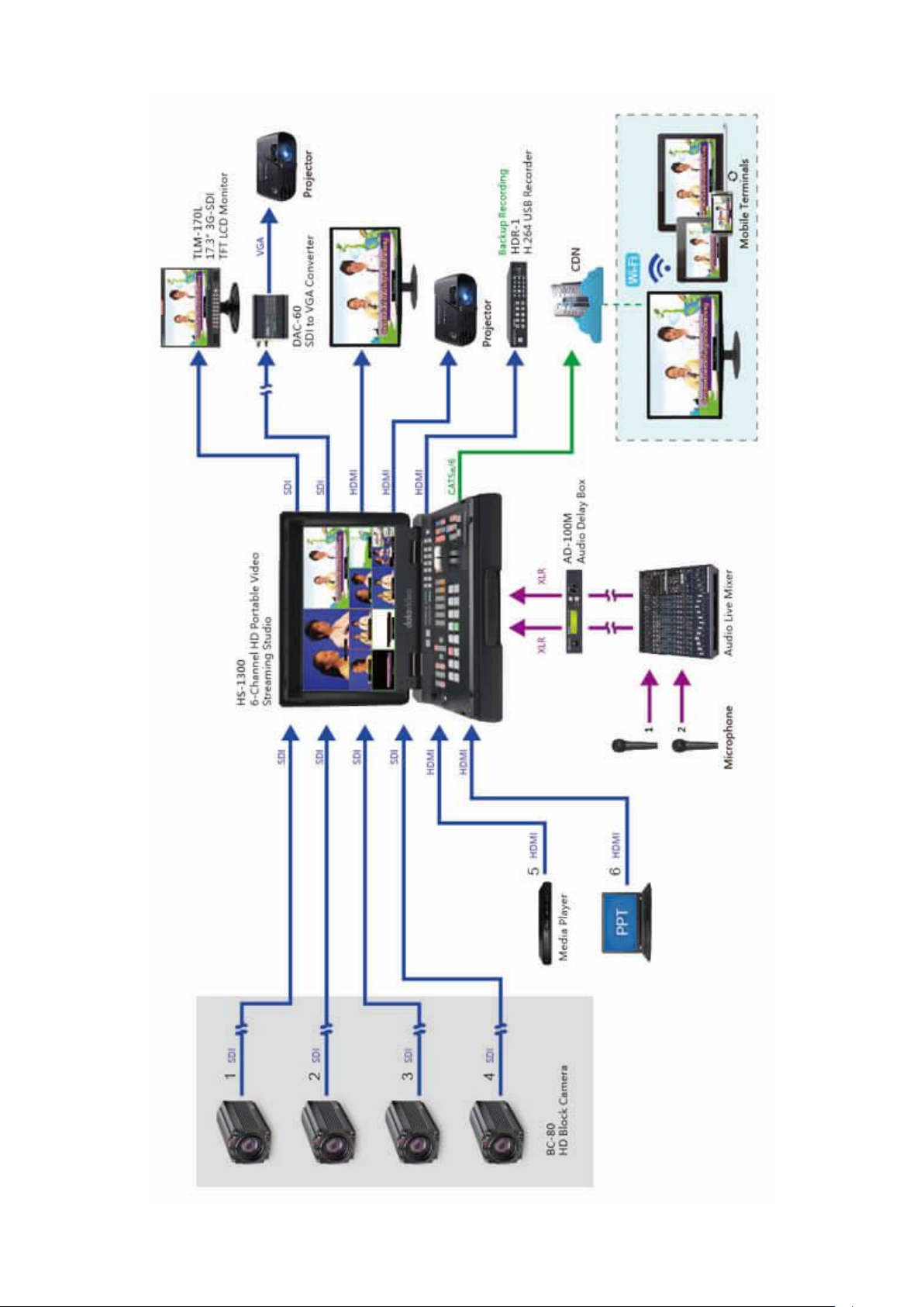
HS-1300 features an easy-to-use video streaming and recording appliance for professional video producers
who need to simultaneously stream a live event and record the master quality version for post-editing.
The HS-1300 is a cost effective 6 channel broadcast-quality hand-carry mobile switcher, it is designed for
live events and TV programs that need to mix a variety of video and audio sources. The HS-1300 is a
lightweight, portable and powerful featured mobile studio solution.
Friendly and advanced features include a 17.3-inch video monitor, which displays the multi-view. The Multiview includes all the input sources, as well as preview and program.
1.1 Features
Simultaneous Live Streaming & Recording
Broadcast quality HD / SD H.264 network streaming
Support different bitrate for recording and streaming
6 video inputs (SDI x 4 + HDMI x 2)
5 Video Output: (SDI x 2 + HDMI x 3)
2 x XLR Analogue Audio Inputs
Flexible Mix/Effects Processor with
- 2 Upstream Keyers supporting Chroma Key & Linear/Luma Key
- 2 DSK supporting Linear & Luma Key Modes
- 1 PIP (assignable to any of the 4 keyers)
- Wipe, Mix & Cut Transitions
- Full M/E Preview function
Any Input (1-6) can be used as a Frame store (Stills Store)
XPT (Cross Point Assignment)
Tally output
GPI Output
One 17.3-inch with a resolution of 1600x900 dots
Easy to use On-screen Menu System for quick setting of parameters
Page 8
8
1.2 System Diagram
Page 9
9
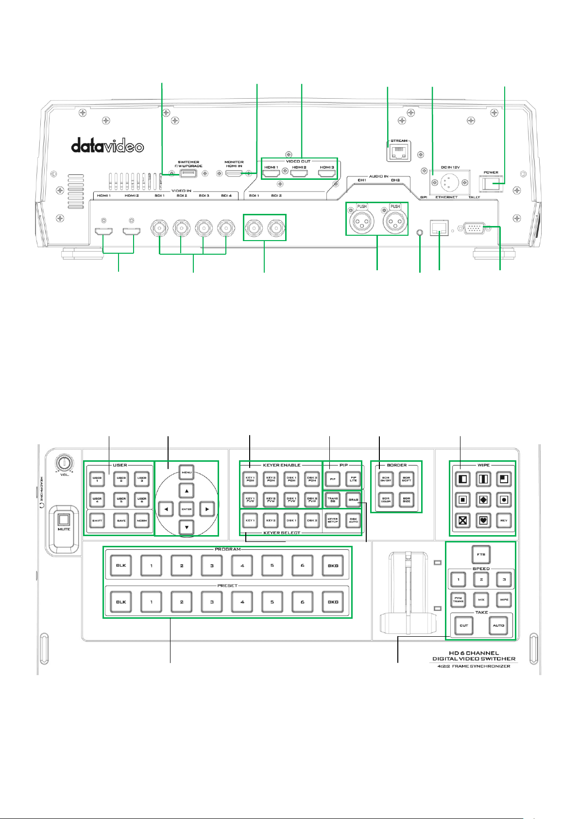
Chapter 2 Connections and Controls
1
Power Switch
8
3 PIN XLR Audio Input 1 – 2
2
4 PIN XLR Power Input Connector
9
GPI Output Connector
3
Monitor HDMI IN (External Video Input)
10
Ethernet Port
4
HDMI Video Input 1 – 2
11
Tally Signal Output
5
HD-SDI Video Input 1 – 4
12
USB Firmware Upgrade Port
6
HD-SDI Video Output 1 – 2
13
Stream Port
7
HDMI Video Output 1 – 3
1
User Memory & Function Keys
6
Background Transition & GRAB
2
Menu Control
7
Wipe Border Setting
3
Keyer Selection
8
Wipe Transition Selection
4
Keyer Source
9
Program & Preview source rows
5
PIP Effect
10
Transition Effect
2 3 12
5
6
7
8 9 10
11
13
1
3 2 8 7 5
4
6
10
9
Page 10
10
2.1 Rear Panel Connections
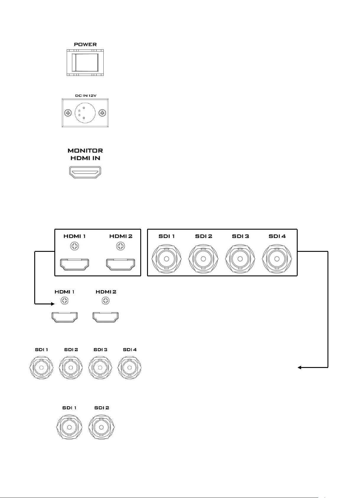
1. POWER SWITCH
Switches the power On / Off.
2. DC Power Input
Connect the supplied 12V 5A PSU to this 4 PIN XLR socket.
3. Monitor HDMI IN (External Video Input)
The HS-1300 provides a useful connection for confidence
monitoring of HDMI sources on location.
Connect one external HDMI input source for monitoring the
live show.
Video Input Modules: The HS-1300 is equipped with six video input channels. Connect the respective
video sources to these video input channels.
4. HDMI Video Input 1-2
The Video Input set includes two HDMI ports.
Note: Please set the INPUT SOURCE in the Switcher Menu.
5. SDI Video Input 1-4
The Video Input set includes four SDI connectors.
Note: Please set the INPUT SOURCE in the Switcher Menu.
6. SDI Video Output 1-2
The BNC output connector is a user defined SDI output.
Note: Please set the OUTPUT SOURCE in the Switcher
Menu.
Page 11
11
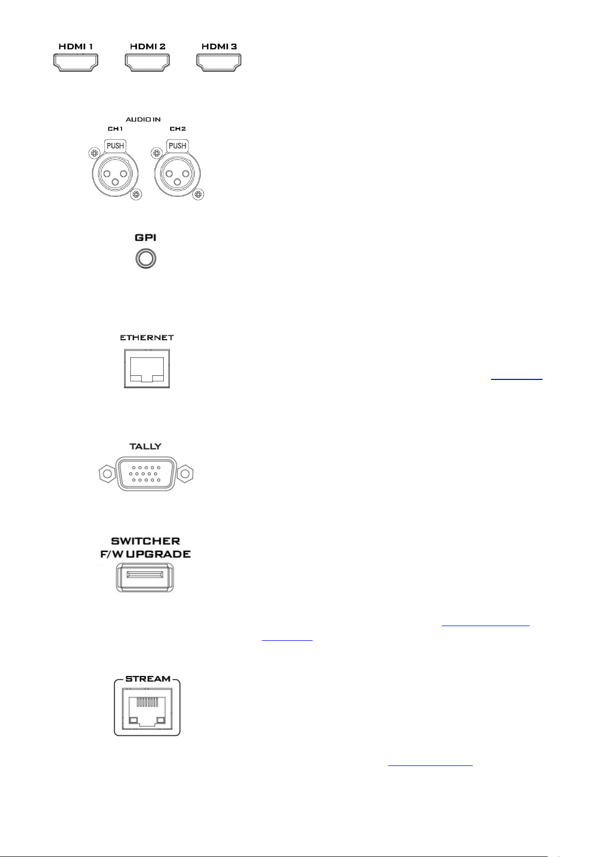
7. HDMI Video Output
All three HDMI ports output Program video.
8. AUDIO Input 1-2
Supports two XLR Balanced Audio Input channels.
9. GPI Output
The GPI socket can be used for simple external control.
Note: Please configure GPI settings in the Switcher Menu.
10. Ethernet Port
The Ethernet port allows the user to transfer files to and
from the switcher on the PC remotely. See Chapter 3 for
details on how you can utilize this port or perform system
setup using this port.
11. Tally Signal Output
Sends Red, and Green tally signals to each channel. Red
indicates On-Air, and Green indicates next camera source.
12. USB Firmware Upgrade Port
Connect the USB drive containing the latest firmware files to
this port and start the firmware upgrade process on the OSD
MENU.
Note: Please refer to the section on Firmware Update
Procedure for firmware upgrade details.
13. Stream Port
The Stream Port allows the user to connect the laptop to the
HS-1300 directly to access the NVS-31 or connect the builtin NVS-31 to any IP network.
Note: Please refer to the Video Streaming section for
device setup details.
Page 12
12
2.2 Switcher Control Panel
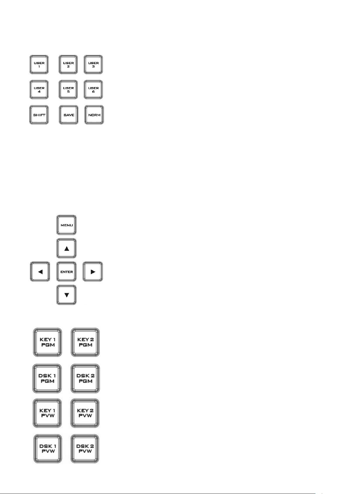
User Memory
User Memory buttons 1-6 allow the user to recall and load previously
saved switcher settings.
SHIFT
There are 12 user memory locations. Under normal circumstances,
Buttons USER 1 to 6 represent user memory locations 1 to 6. To load
settings saved in locations 7 to 12 to buttons USER 1-6, simply press the
SHIFT button.
SAVE: User Memory Save
The SAVE button saves the current switcher settings. To save, keep holding down this button and then
select the User Memory number by pressing the corresponding User Memory button.
Normalise Button
The NORM button resets the currently opened menu item to the default values.
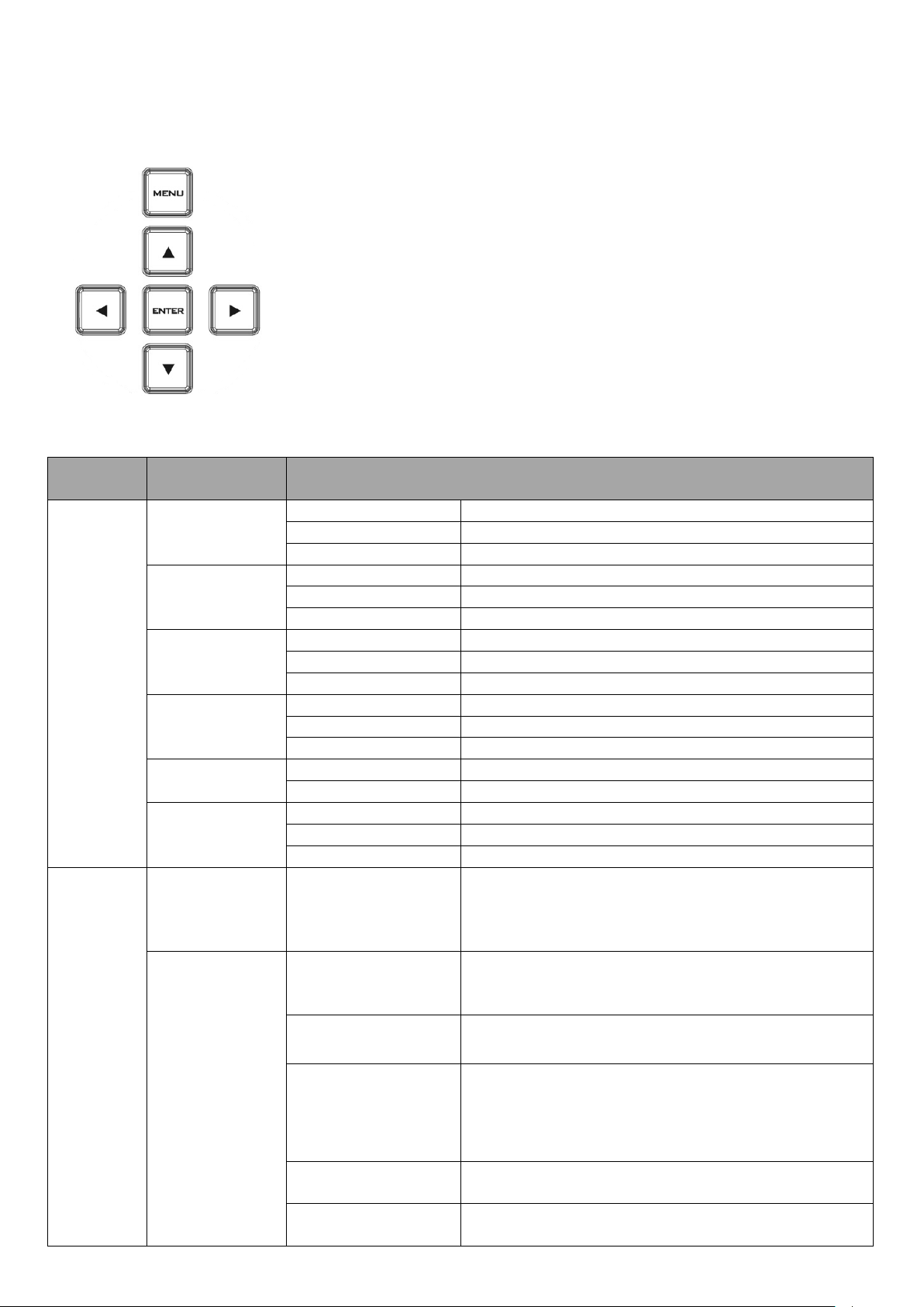
Menu Control
Press the MENU button in the HS-1300 function section to enter the
System Configuration Menu. Press the UP, DOWN, LEFT, and RIGHT
arrow buttons to browse the menu options and change values. Use the
ENTER button to save and confirm any setting that has been changed. To
Exit, simply press the MENU button again.
Key 1 PGM enables key 1 on the Multi view and PGM output
Key 2 PGM enables key 2 on the Multi view and PGM output
DSK 1 PGM enables DSK 1 on the Multi view and PGM output
DSK 2 PGM enables DSK 2 on the Multi view and PGM output
Key 1 PVW enables key 1 on the Multi view and PVW output
Key 2 PVW enables key 2 on the Multi view and PVW output
DSK 1 PVW enable DSK 1 on the Multi view and PVW output
DSK 2 PVW enable DSK 2 on the Multi view and PVW output
User Memory and Function Keys
Menu Control
Keyer Selection
Page 13
13
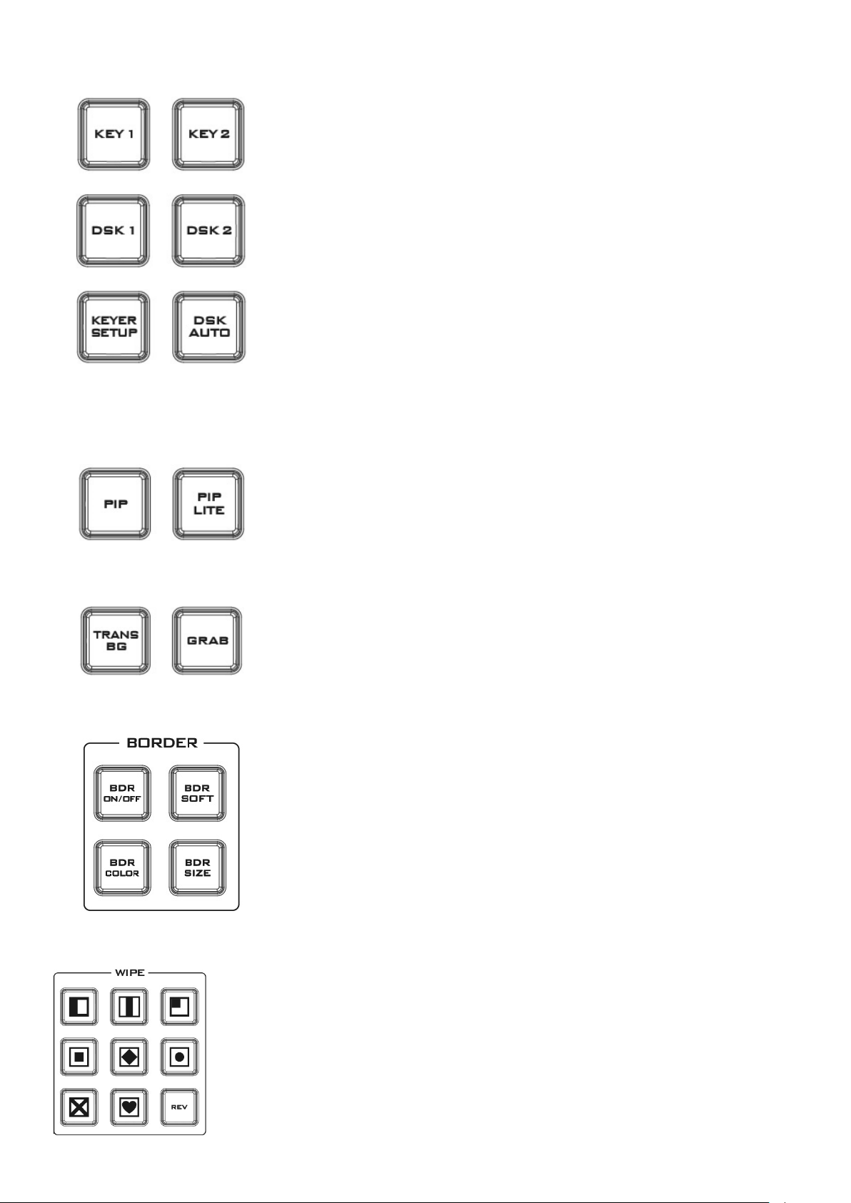
Keyer Source
Selection of Keyer Source from Program / Preset Row
Keep holding down one of these buttons to enter key select mode and
fill select mode. Select key source from the Program row and fill source
from the Preset row.
The selected source button will flash.
KEYER SETUP
Press this button to open Keyer configuration menu on the Multi view
output, and the opened configuration menu corresponds to the selected
keyer (Key 1/Key 2/DSK 1/DSK 2).
DSK AUTO
Auto DSK transition function either transitions “DSK 1 or DSK 2
individually” or transitions “DSK 1 and DSK 2 simultaneously”
PIP enables the PIP key mode
PIP LITE enables the PIP LITE key mode
TRANS BG enables Background Transition between Program / Preset
GRAB grabs the current Program video image to Input 6.
BDR ON/OFF turns the WIPE border function ON/OFF
BDR SOFT configures the WIPE border softness
BDR COLOR selects the WIPE border color
BDR SIZE adjusts the WIPE border thickness
PIP Effect
Background Transition & GRAB
Wipe Border Setting
Wipe Transition Selection
WIPE Transition Selection
The HS-1300 has 8 user defined wipe buttons that allow the user to select WIPE
transition effect directly from the control panel.
The REV button reverses the direction of the selected WIPE.
All wipes can have an optional colour border applied. The wipe border width and
colour are chosen within the menu system.
Page 14
14
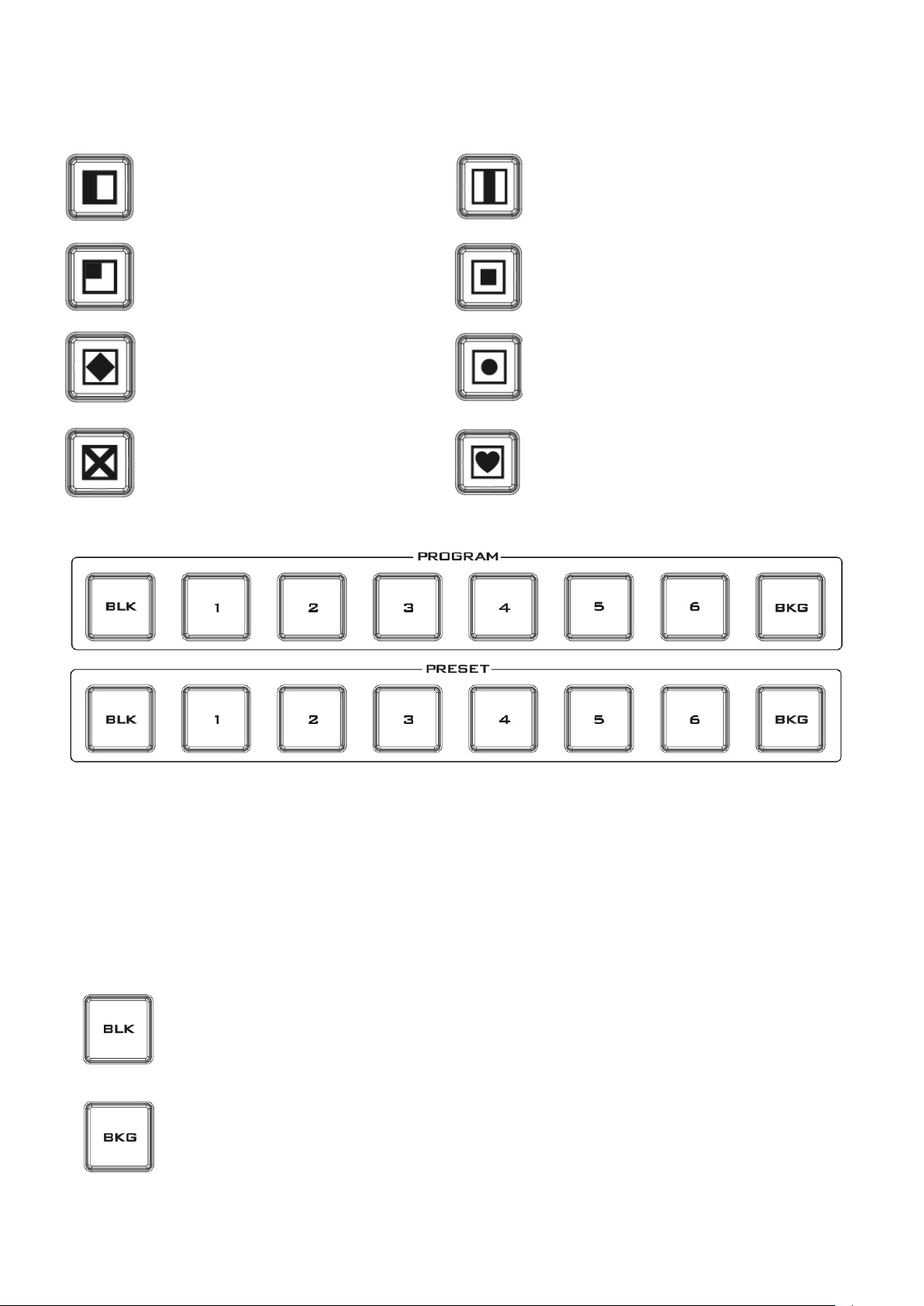
Vertical Wipe Left to Right
Vertical Wipes from Centre to Left and
Right sides
Upper Left corner Wipe to Lower
Right corner
Box Wipe from Centre to outside edges
Diamond Wipe from Centre to
outside edges
Circle Wipe from Centre to outside
edges
Cross Wipe from Centre to outside
edges
Heart Wipe from Centre to outside
edges
The Program row of buttons is the active channel, this is the live output. The active channel will appear
as the Program Output. You can switch or CUT from one video source to another directly on the
Program row. You will see the multi view Program output change as you press different keys along this
top row of buttons.
The Preset row is the cued channel; this channel will appear in the Preview window. The Preset row
selection decides which input will be transitioned next when using any of the transition controls.
Buttons 1, 2, 3, 4, 5 and 6 are video source buttons.
BLK
Black background – the black background, for use on the Program and Preset row.
BG
Background button – assigns a background colour or colour bars for use on the
Program and Preset row.
Transitions can be performed manually using the T-Bar or automatically by using the SPEED and AUTO
TAKE buttons.
Program & Preview Source Row
Page 15
15
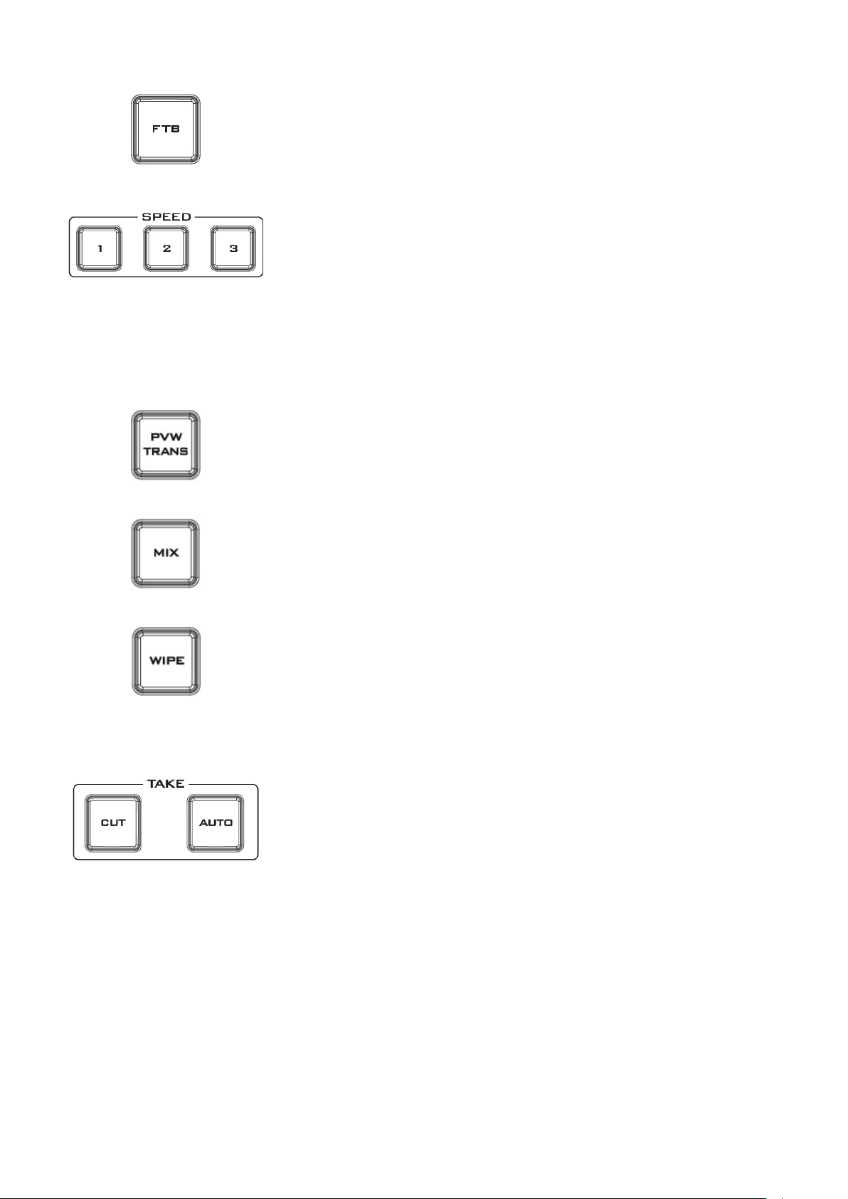
Transition Effect
FTB
Fade To Black, this button fades the current video program source to
black. When pressed again it acts in reverse from complete black to
the currently selected program video source.
SPEED
There are three speed buttons which can be defined by the user. By
pressing a speed button the user is choosing the rate of transition or
time taken when using the AUTO TAKE button.
Transition Speed (1, 2 and 3):
Button 1= 12 frame duration, 2= 25 and 3= 50 at 1080i50
Button 1= 15 frame duration, 2= 30 and 3= 60 at 1080i60
PVW TRANS
Transition shown on PVW only.
MIX
This button enables MIX transition effect.
WIPE
This button enables WIPE transition effect. The WIPE button must be
selected when a wipe effect transition between the selected Program
and Preset sources is required. This WIPE effect is produced by moving
the T-Bar manually or pressing the AUTO TRANS button.
CUT
This performs a simple immediate switch from the current main source
to the selected sub source. The selected transition wipe or MIX is not
used.
AUTO TAKE
This performs an automated switch from the current program source
to the selected Preview source. The selected transition wipe or MIX
will also be used. The timing of the transition is set by the chosen
Speed button.
Page 16
16
T-Bar
This performs a manually controlled transition from the current
program source to the selected preset source. The selected transition
wipe or dissolve will be used. When the T-Bar has travelled as far as it
can go, the transition between sources is complete. The T-Bar has
indicators next to it, which light when the transition is complete.
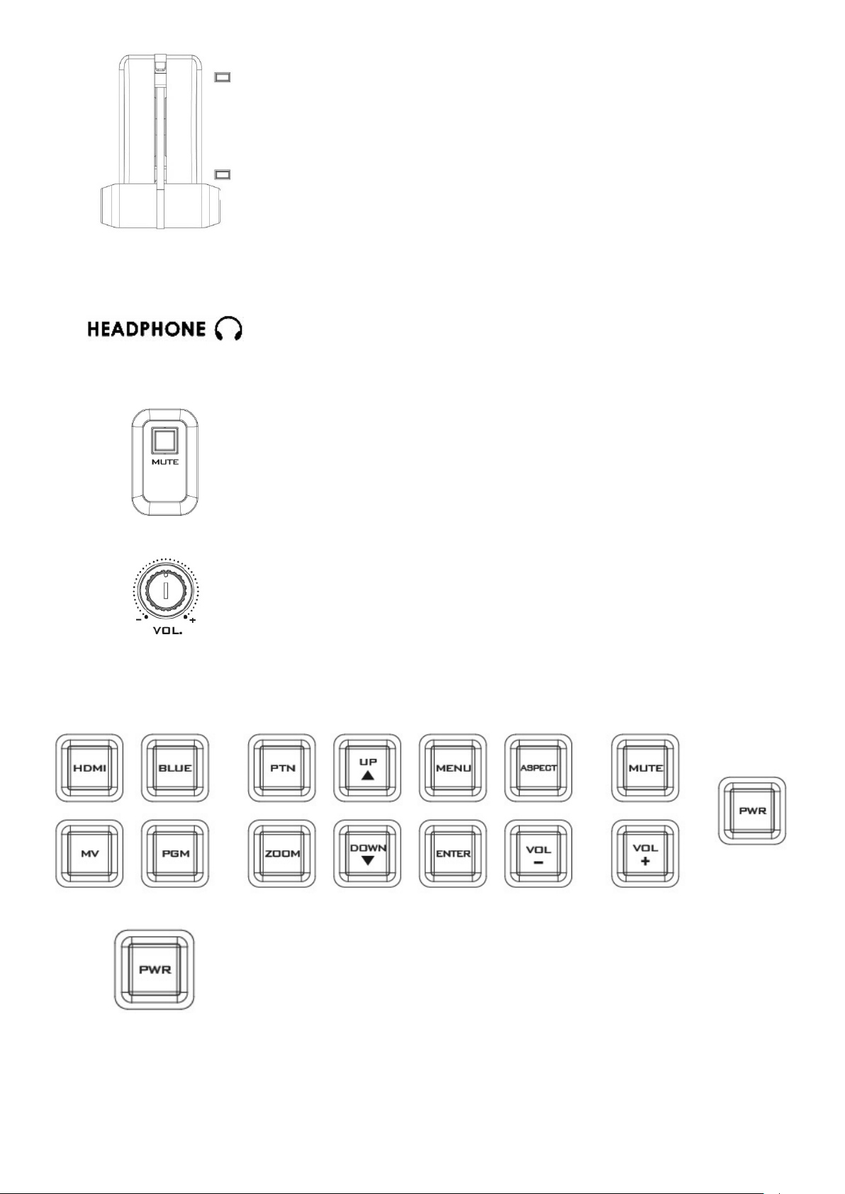
Audio Control
Headphone Socket
¼”/ 6.3mm Stereo Headphone Socket for conventional headphones.
MUTE
This button mutes the headphone audio.
Headphone Volume Control
Controls Headphone or Headset volume level.
Power
Switches the HS-1300 Monitor Power ON / OFF
2.3 Monitor Control Panel
Page 17
17
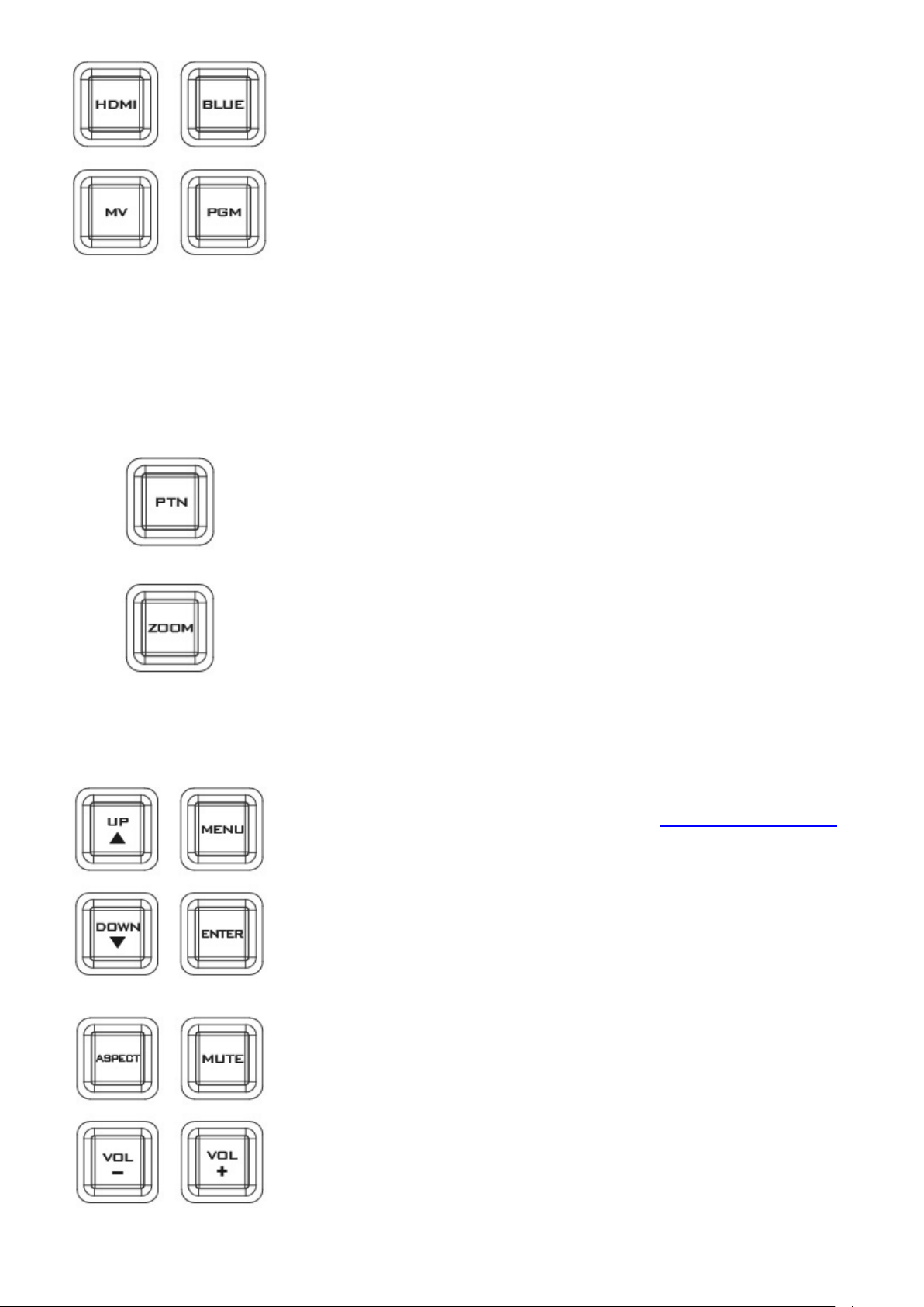
Source Select Buttons
Select the type of source you are using - HDMI, MV (multi-view), PGM
(program).
HDMI
Switch the 17.3” built-in monitor to display the video source plugged into
the MONITOR HDMI IN port.
BLUE
Press this button to eliminate the red and green component of input
signals. Only the blue component of an input is displayed on the screen.
MV
Press this button to set the Monitor to MULTIVIEW mode.
PGM
Press this button to set the Monitor to PROGRAM view.
PTN
When pressed displays internally generated SMPTE 75% Colour Bars. Press
again to return to the previously selected video input.
ZOOM
This feature is designed for use with HD-SDI and HDMI sources above 720p
resolution. Press this button to zoom in to the video on the display. This is
strictly a zooming function and does not alter the native aspect ratio of the
source pixels to fill the screen.
The ZOOM button allows you to toggle the Pixel Zoom feature between
zoom x1, x2, x4 and x8.
Menu Navigation Buttons
Display and navigate the set up menus - See Monitor Menu Options for
more details.
Aspect Ratio Button
Sets the Aspect Ratio to 16:9 / 4:3
Volume Control
Adjusts the speaker / headphone volume up / down.
MUTE
Mutes the audio from the internal speakers or headphone socket.
Page 18

18
RECORD
Press the RECORD button to start video recording.
STREAM
Press the STREAM button to start video streaming.
SD Card Slot
Insert an SD card into the SD card slot for video recording.
Note: Do not remove SD card while it is being written as doing so may
result in corrupted video files.
Page 19
19
Chapter 3 Network Setup
An RJ-45 Ethernet cable.
Windows 7/8/10 laptop or PC.
The Datavideo Switcher Image
Import/Export software.
The Ethernet port on the back panel of the HS-1300 allows the user to import or export Stills/Clip files and
User memory using the Switcher Image Import/Export software. The Switcher Image Import/Export
software allows you to manipulate user memories, still pictures and clip files.
Section 3.1 discusses direct connection between the HS-1300 and your Windows computer. In Section 3.2,
we will show you how you can remotely set up the Switcher Image Import/Export software with your
switcher after it is installed on your Windows computer.
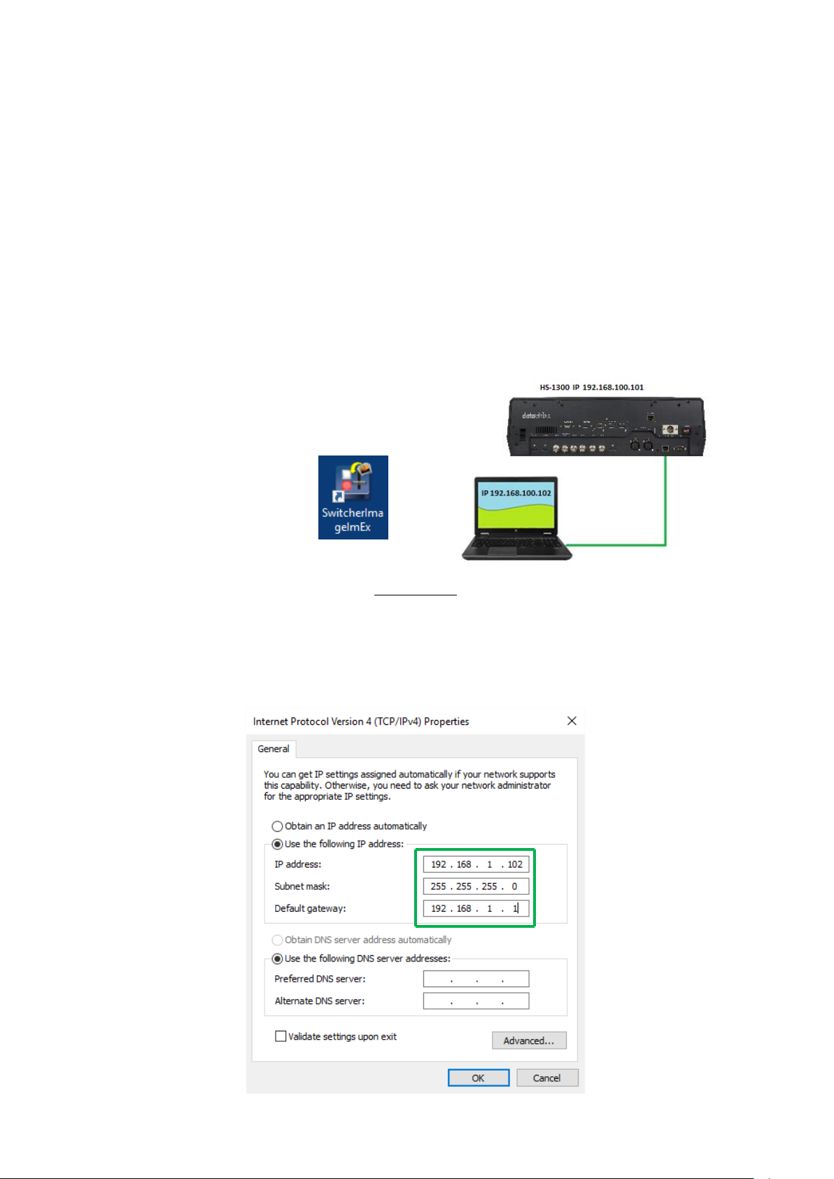
3.1 Switcher Setup with a Windows Computer
When new from the factory the HS-1300 will initially have a static IP address of 192.168.100.101. The
unit can be directly connected to a Windows-based computer using an RJ-45 ethernet cable. The following
set up should allow you to initially configure the unit before moving it to an existing DHCP / LAN network.
Instructions
1. First connect the HS-1300 and the Windows computer together using an RJ-45 ethernet cable.
2. Turn on the Windows computer and set it to static IP setup within the Windows Network and Sharing
Centre. In our example below the computer is given the following IP settings so that the computer
matches the same IP range as the switcher.
3. Now install the Switcher Image Import/Export software to the computer.
Page 20
20
3.2 Installing the Switcher Image Import/Export software to a Windows Computer
The HS-1300 can be connected to a simple IP network and accessed using Windows-based software. If you
have not already set up the HS-1300 with a computer then please follow the instructions in the previous
section.
Please download the latest software from the Datavideo HS-1300 web page. See:
www.datavideo.com
The install executable file [.msi] will be called SwitcherImageImEx_vXXXX.msi
The vXXXX represents the latest version number.
Double click this .msi file then follow the on screen install wizard prompts.
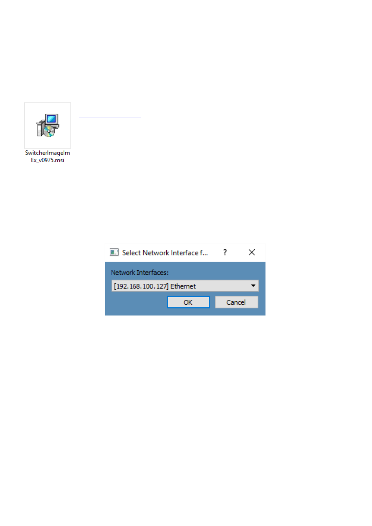
Once installed launch the Switcher Image Import/Export software.
The Switcher Image Import/Export software has a built-in IP finder, which is designed for PC with multiple
Ethernet cards or DHCP network environment. Please note IP finder can only find devices that are on the
same network domain as the PC. If you cannot remember your device IP, please press the RESET button to
restore the default network settings. Upon launch of the Switcher Image Import/Export software, you will
be prompted to select one Ethernet Interface Card.
Once selected, click OK to start the scanning process.
Note: Please make sure the selected interface card is on the same network domain as the HS-1300
device.
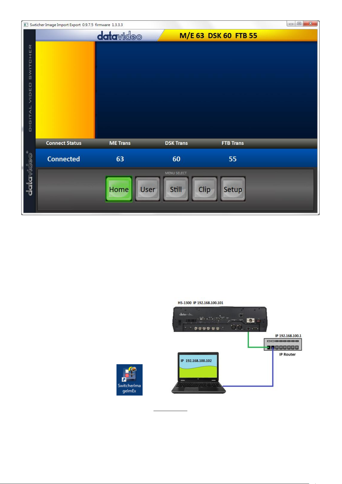
Once the HS-1300 device is found, the software will connect with the switcher hardware over the IP set up
described in the previous section. If the connection is successfully established, on the software user
interface as shown in the diagram below, the Connect Status will show “Connected” (will display Not
Connected if disconnected).
Page 21
21
Router Based DHCP Setup
An IP router which can assign/give IP
addresses.
Two RJ-45 patch leads.
Windows 7/8/10 laptop or PC.
The IP router Administrator login and
password.
The Datavideo Switcher
Image Import/Export
software.
The computer software can also access the HS-1300 over an existing TCP/IP LAN type network. In order to
initially set up the HS-1300, you may need the assistance of your local I.T. specialist to help with the
network settings. To help guide you, we have included a simplified network setup example below, further
advice may be available through your dealer locally or your Datavideo regional office.
To create this simple dedicated HS-1300 IP network you will need:
1. First connect the router to the HS-1300 and the Windows computer using two RJ-45 patch leads.
2. Turn on the Windows computer and set it to DHCP setup within the Windows Network and Sharing
Centre.
3. Now click the Windows start button and run the CMD prompt window.
4. At the command line > : _ type IPCONFIG and press enter.
Instructions
Page 22
22
5. The DEFAULT GATEWAY number displayed should be the router’s current IP address.
6. Enter the DEFAULT GATEWAY IP address into the address bar of the computer’s web browser.
7. The web browser should display the login window for the router. Enter the router’s login and/or
password.
The login details may be written on a sticker on the router itself or noted in the manual for the router.
8. Once logged into the router we need to change the router to supply IP addresses in the
192.168.100.xxx range. Use the router’s LAN Setup or Configure LAN option to set the router’s IP
address as 192.168.100.1 and click save / apply.
9. Now reboot the router and power ON the HS-1300.
10. Log into the router again using the web browser and the router’s new IP address 192.168.100.1
11. Use the router’s LAN Setup or Configure LAN option again, within this option there should be another
option called Address Reservation or Client List.
12. The two devices connected to the router should be listed here, the computer and the HS-1300.
13. The computer, because it is set for DHCP, will already have an IP address automatically assigned to it in
this list.
14. The HS-1300 will also be listed with its default IP address of 192.168.100.101 if it is not changed.
15. Click save / apply then reboot the router again.
16. Close the web browser and CMD windows.
17. Now install the Switcher Image Import/Export software to the computer.
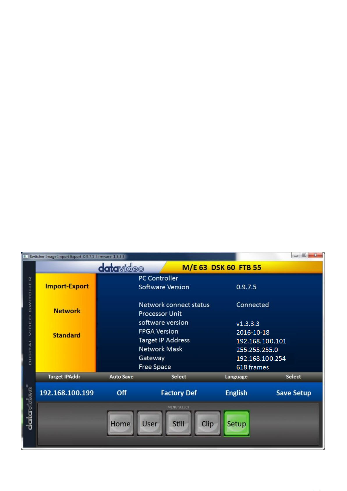
Setting the Target IP Address with the Switcher Image Import/Export Software
Click Setup button in the MENU SELECT pane and the current IP Network settings are shown alongside the
software version.
Page 23

23
If the network settings are wrong then you may not be able to access the HS-1300. Always keep a note of
the last IP settings used and change these settings carefully to avoid problems.
Target IP address – This IP address is the location on the local network, or the internet, where the software
can talk to the HS-1300. By clicking the Target IP address you can enter a new address, once entered click
Save Setup. The next time the Image Import/Export Software is opened, it will try to contact the switcher
on this new Target IP address.
Network – This option in the yellow menu column allows you to change the network options on the HS-
1300. When delivered from the factory the default static IP settings should be:
Addr Mode: Static (a manually set IP address that does not change even after power cycling the HS1300 unit)
Target IP address: 192.168.100.101
Network Mask: 255.255.255.0
Gateway: 192.168.100.1
DHCP Setup - If the IP set up method is changed to DHCP then each time the HS-1300 is started, it may be
given a different IP address by the network. Only use this method if you know how to find the HS-1300 on
the internal IP network. A device on the network (usually a router or server) will automatically assign an IP
address to the HS-1300. The other settings such as IP address, Subnet Mask and Gateway may appear blank
within the Switcher Image Import/Export software as these would be automatically set by network
router/DHCP server.
Page 24
24
Chapter 4 Switcher OSD MENU
When the MENU button is pressed the Main Menu list is displayed on the
HS-1300 monitor.
This section covers the Menu options in the order that they appear on the
HS-1300 monitor. These settings may also appear in more detail elsewhere
in this instruction manual. Options may vary depending on the firmware
version in use.
Once the chosen setting has been confirmed with the ENTER button, it is
stored within the switcher’s non-volatile memory.
Main
Options
Sub-Options
Parameters
Start
Transition
(Duration)
M/E
Mix Effect
DSK
Downstream Key Effect
FTB
Fade-to-Black Effect
Type
Clip
Wipe
Mix
Wipe Effects
Wipe
Wipe Effect Presets
Soft
Border Softness
Width
Border Width
Border
Luma
Border Color Luma
Sat
Border Color Saturation
Hue
Border Color Hue
Position
X
Horizontal Position
Y
Vertical Position
Matte
Luma
Background Matte Luma
Sat
Background Matte Saturation
Hue
Background Matte Hue
Keyer
Keyer
DSK 2
DSK 1
Key 2
Key 1
Keyer Selection
Keyer Ctrl
Chroma
Luma
Linear
Type of Keyer
P-in-P Lite
P-in-P
P-in-P lite window enable
P-in-P window enable
Priority
Optional and only available when Key 1 and Key 2 are
selected.
Bot – Set to bottom layer
Top – Set to top layer
Lift
Parameter for dark/black areas of the overall foreground
key image, ranging from -100% to +100%.
Gain
Parameter for light/white areas of the overall foreground
key image, ranging from 0 to 16.0
4.1 Overview
Page 25

25
Opac
Parameter for transparency of the overall foreground key
image, ranging from 0% to 100%.
Key Source
Bars
Matte
Input 6
Input 5
Input 4
Input 3
Input 2
Input 1
Black
Key Source Selections
Fill
Fill Source Selection from Bars /Matte /Input 6 /Input 5
/Input 4 /Input 3 /Input 2 /Input 1 /Black
Mask
Left
Left sets the left edge of the keyer mask
Right
Right sets the right edge of the keyer mask
Top
Top sets the top edge of the keyer mask
Bottom
Bottom sets the bottom edge of the keyer mask
Chroma
Keyer
DSK 2 (N/A)
DSK 1 (N/A)
Key 2
Key 1
Key Source
Bars
Matte
Input 6
Input 5
Input 4
Input 3
Input 2
Input 1
Black
Key Source Selections
CK Setup
CK Auto
Calculation of the best Hue & Luma values for the
current Keyer source
Hue
Parameter for color of the chroma key, ranging from 0 to
355.
Luma
Parameter for luma of the chroma key, ranging from 0 to
100%.
K Range
Setting the range of colors that match the background
color to be keyed, ranging from 0 to 360.
K Fgnd
Adjusts the performance of the chroma key in dark or
black areas, ranging from -100% to 100%.
K Bgnd
Adjusts the performance of the chroma key in light or
white areas, ranging from K Fgnd value (min = 0) to
100%.
Hi-Light
Boosts the foreground key in high luminance area,
ranging from 0 to 100%.
Lo-Light
Boosts the foreground key in low luminance area,
ranging from 0 to 100%.
Bg-Supp
Bg-Supp turns ON/OFF background suppress
Mask
Left
Left sets the left edge of the keyer mask
Right
Right sets the right edge of the keyer mask
Top
Top sets the top edge of the keyer mask
Bottom
Bottom sets the bottom edge of the keyer mask
P-in-P
P-in-P Src
Key 1 / Key 2
Select either Key 1 or Key 2 in the “Keyer” Option and
enable P-in-P
Position
X
Horizontal PIP Position
Page 26

26
Y
Vertical PIP Position
Size
PIP Size
Border
Luma
PIP Border Luma
Sat
PIP Border Color Saturation
Hue
PIP Border Color Hue
Width
PIP Border Width
Crop
Left
Left Edge of the Crop
Right
Right Edge of the Crop
Size
Size of the Crop
Top
Top Edge of the Crop
Bot
Bottom Edge of the Crop
P-in-P
Fine
Normal
Fine tune of parameters X/Y/Size with step size 0.1
Adjustment of parameters X/Y/Size with step size 1
P-in-P Lite
P-in-P Keyer
Key 1 / Key 2
Select either Key 1 or Key 2 in the “Keyer” Option and
enable P-in-P Lite
Position
X
Horizontal PIP Position
Border
Luma
PIP Border Luma
Sat
PIP Border Color Saturation
Hue
PIP Border Color Hue
Width
PIP Border Width
Crop
Left
Left Edge of the Crop
Right
Right Edge of the Crop
Size
Size of the Crop
Top
Top Edge of the Crop
Bot
Bottom Edge of the Crop
P-in-P Lite
Fine
Normal
Fine tune of parameter X with step size 0.1
Adjustment of parameter X with step size 1
Inputs
Input 1
Black
Black Level
White
White Level
Chrom
Chroma Level
Input 2
Black
Black Level
White
White Level
Chrom
Chroma Level
Input 3
Black
Black Level
White
White Level
Chrom
Chroma Level
Input 4
Black
Black Level
White
White Level
Chrom
Chroma Level
Freeze
1
Still
Freeze
Live
2
Still
Freeze
Live
3
Still
Freeze
Live
4
Still
Freeze
Live
5
Still
Freeze
Live 6 Still
Page 27

27
Freeze
Live
Crosspoint
1
Input 6
Input 5
Input 4
Input 3
Input 2
Input 1
OFF
2
Input 6
Input 5
Input 4
Input 3
Input 2
Input 1
OFF
3
Input 6
Input 5
Input 4
Input 3
Input 2
Input 1
OFF
4
Input 6
Input 5
Input 4
Input 3
Input 2
Input 1
OFF
5
Input 6
Input 5
Input 4
Input 3
Input 2
Input 1
OFF
6
Input 6
Input 5
Input 4
Input 3
Input 2
Input 1
OFF
Outputs
Output
SDI1/ SDI2
Input 6
Input 5
Input 4
Input 3
Input 2
Input 1
CLN PVW (Clean PVW)
CLN PGM (Clean PGM)
PG + DSK
PVW
PGM
Page 28

28
MultiV (Multi view)
HDMI (17.3” Built-in
Monitor Resolution)
1080i
1080p
Audio
Mode
ON/OFF
Src
Input 6
Input 5
Input 4
Input 3
Input 2
Input 1
Follow
External
SDI 1
SDI 1 Audio Enable (ON)/Disable (OFF)
SDI 2
SDI 2 Audio Enable (ON)/Disable (OFF)
HDMI (17.3” Built-in
Monitor)
HDMI Audio Enable (ON)/Disable (OFF)
Tally Mode
Audio Mixer
Select either the audio mixer input or the tally light
connection.
Normal
GPI Out
ON/OFF
GPI Enable/Disable
Mode
Level/Pulse
Width
Pulse width
Input 1-6
GPI-out assignment
Delay
0-99
Multiviewer
AutoNum
Auto number input labels (ON/OFF)
Label Inf
Input label is followed by information which describes
the input as still, live or frozen image (ON/OFF)
Trns Lab
Turn the background of the label from a solid colour to
transparent (ON/OFF)
Stills
Load Still
Load
Pressing this button loads the selected still picture
source
Still Memory Location
0-500
Destination
Input6
Input5
Input4
Input3
Input2
Input1
Thumbnail Picture - 1
Preview of the previous image
Thumbnail Picture
Preview of the image to be loaded
Thumbnail Picture + 1
Preview of the next image
Save Still
Save
Pressing this button saves the selected still picture
Source
Input6
Input5
Input4
Input3
Input2
Input1
Still Memory Location
0-500
Grab Still
Grab
Press this button to grab the current program view
Grab Destination
Input6
Input5
Input4
Input3
Input2
Input1
Page 29

29
Freeze
1
Sets the Frame store mode of Input 1 to Clip / Still /
Freeze / Live
2
Sets the Frame store mode of Input 2 to Clip / Still /
Freeze / Live
3
Sets the Frame store mode of Input 3 to Clip / Still /
Freeze / Live
4
Sets the Frame store mode of Input 4 to Clip / Still /
Freeze / Live
5
Sets the Frame store mode of Input 5 to Clip / Still /
Freeze / Live
6
Sets the Frame store mode of Input 6 to Clip / Still /
Freeze / Live
User Mems
Load Mem
Memory
Memory Selection from 1 to 999
Load
Selection of this button loads the selected memory
Save Mem
Memory
Memory Selection from 1 to 999
Save
Selection of this button saves to the selected memory
Load Clip
Load
Selection of this button loads the selected clip
Clip Memory Location
Memory locations from 0 to 999
Thumbnail Clip - 1
Preview of the previous clip
Thumbnail Clip
Preview of the clip to be loaded
Thumbnail Clip + 1
Preview of the next clip
Clear Clip
Clear the loaded clip
Delete Clip
Remove the clip from the memory location
Setup
Standard
1080i/50
Resolution Selections from
1080i/50/59.94/60
720p/60/59.94/50
Save Setup
Saves the selected resolution
Audio
Level
EBU
SMPTE
AUTO
Menu Mode
Advanced
Full
Basic
Reduced
Menu Pref
Blue / Grey
Selection of menu color
Transp
Menu transparency level of 0/1/2
Size
Menu size of Normal/Small/Large
Menu Pos
Bottom
Right
Left
Top
Centre
This option sets the menu position
Auto Save
ON / OFF
Automatically saves the last settings before the machine
is shut down; once turned ON auto save also occurs
upon every Still Load.
Factory Def
Reset
Factory Default Reset loads the default configuration
from memory point 0 for all configuration options except
for the Setup.
Reset Names
Resets the Multiviewer labels to the default settings
Network Default
Resets the network settings
Language
English
Traditional Chinese
Simplified Chinese
Software
Upgrade
This starts the FW upgrade process
Please refer to the Firmware Upgrade section for the USB
firmware update process.
Page 30

30
4.2 Functions
Start
Transition
M/E
60
DSK
60
FTB
60 Type
Wipe
Wipe Effects
Wipe
1
Soft
0%
Width
0%
Border
Luma
100%
Sat
80%
Hue
178
Position
X
0% Y 0%
Matte
Luma
100%
Sat
80%
Hue
0
Ip Addr: 192.168.100.101
Start
Transition
M/E
60
DSK
60
FTB
60
Wipe Effects
Wipe
1
Soft
0%
Width
0%
The HS-1300 HD 6-Channel Portable Video Studio offers the user an OSD menu to perform several image
effect configurations, such as Picture-in-Picture, keyers, downstream keys, still pictures and etc. The user
can also configure the I/O by selecting the Inputs and Outputs options. In addition, under the setup
options, the user is allowed to set the menu color, size, position and language.
The OSD Menu also gives the user the flexibility to switch between basic and advanced modes. The basic
mode is generally a condensed version of the advanced menu mode. The following sections will show you
the options available in these two modes.
Start
The “Start” option generally allows the user to set the Transition duration, the Transition type, and various
WIPE effect parameters. The OSD menu display is illustrated in the table below.
Advanced Mode
Basic Mode
Transition
The transition option allows the user to set the transition duration, in frames, for switching to the PGM
view when using the AUTO, DSK and FTB buttons. The sub-options are (AUTO) Mix Effect (M/E),
Downstream Key (DSK) and Fade-To -Black (FTB). If the M/E is set to a value of 50 then the transition will
take effect over a period of 50 frames or roughly 2 seconds. When the AUTO button is pressed, the
transition will take the current M/E value.
Wipe Effects
This sub-option allows the user to select the desired Wipe Transition Effect and configure the wipe’s border
softness and width.
Wipe – Wipe Effect Selection.
Soft – A low value results in a solid edge border and a high value gives a soft diffused border.
Width – A low value results in a thin border and a high value gives a wide border.
Border
After selecting this sub-option, the user will then be allowed to fine-tune the border color by adjusting the
Luma, Saturation and Hue values, i.e. Luma, Sat and Hue.
Page 31

31
Position
X
Y
Positive value: position the wipe centre to the right
Negative value: position the wipe centre to the left
Zero value: Position the wipe centre at the screen
centre
Positive value: move the wipe centre up
Negative value: move the wipe centre down
Zero value: Position the wipe centre at the
screen centre
Keyer
Keyer
Key 1
Keyer Ctrl
Chroma
P-in-P
Priority
Bot
Lift
0%
Gain
1.0
Opac
100%
Key Source
Input 1
Fill
Input 3
Mask
Left
0%
Right
0%
Top
0%
Bot
0%
Position allows the user to adjust the centre position of some wipes (e.g Circle & Elipse). X represents the
horizontal position and Y represents the vertical position.
Matte
The user can configure the Matte Luma, Saturation and Hue under this sub-option.
IP Address
The displayed IP address allows the user to connect to the switcher from a remote location where network
connection is available.
Keyer
In this option, the user is able to configure four keyers, which are Key 1, Key 2, DSK 1 and DSK 2.
Advanced Mode = Basic Mode
Keyer Control
There are three keying modes available: Linear, Luma, and Chroma.
After the keying mode is chosen, if only one source is enabled for the keyer, select the source in Key
Source. If two sources are enabled for the keyer, select the respective sources in Key and Fill Sources. You
may also select P-in-P or P-in-P Lite to apply the keying effect to the P-in-P window.
Please note:
If Luma is selected, fine tune the Luma Keyer parameters (Lift, Gain and Opac) in the Keyer option.
If Chroma is selected, fine tune the Chroma Keyer parameters in the Chroma option.
If P-in-P is selected, fine tune its parameters in the P-in-P option.
If P-in-P Lite is selected, fine tune its parameters in the P-in-P Lite option.
For example, if the user selects Key 1 Chroma P-in-P, you will be performing chromakeying of the Pin-P image after the relevant chroma keyer parameters are adjusted in the Chroma option.
Priority sets the key image to either the top layer or bottom layer and is only available if Key 1 or Key 2 is
selected.
The Keyer Control also allows the user to adjust lift, gain and opacity of the key image.
Page 32

32
Lift adjusts the dark/black areas of the key image.
Bars
Matte
Input6
Input5
Input4
Input3
Input2
Input1
Black
Bars
Matte
Input6
Input5
Input4
Input3
Input2
Input1
Black
Chroma
Keyer
Key 1
Key Source
Input 5
CK Setup
CK Auto
Hue
120
Luma
100%
KRange
170
K Fgnd
15%
K Bgnd
67%
Hi-Light
0%
Lo-Light
0%
Bg-Supp
On
Mask
Left
0%
Right
0%
Top
0%
Bot
0%
Bars
Matte
Input6
Input5
Input4
Input3
Input2
Input1
Black
Gain adjusts the light/white areas of the key image.
Opacity adjusts the transparency of the overall foreground key image.
Key Source
This sub-option allows the user to assign the key source; various options are listed below:
Fill Source
This sub-option allows the user to assign the fill source if Split is selected; various options are listed below:
Mask
The Mask feature allows the user to configure the Mask in chroma, luma or linear mode.
Left – Left sets the left edge of the keyer mask.
Right – Right sets the right edge of the keyer mask.
Top – Top sets the top edge of the keyer mask.
Bottom – Bottom sets the bottom edge of the keyer mask.
Chroma
In this option, the user will be able to find all the parameters needed to perform chromakeying of the
green backdrop.
Advanced Mode = Basic Mode
Keyer
First of all, select the Keyer that you would like to enable for the chromakeyer (Key 1, or Key 2) and then
select one Key Source from all available Key Sources listed in the table below.
CK Setup
In this sub-option, the user will be able to fine tune various chroma keyer parameters.
CK Auto: This function calculates the best Hue & Luma values for the current Key Source.
Hue: This parameter adjusts the color of the chroma key. A typical green screen value will be around 120.
Blue screen value will be around 240.
Luma: This parameter adjusts the luma value of the chroma key
Page 33

33
Key Range (KRange): Key Range sets the range of hues or colors (0 – 360 degrees) that closely match the
P-in-P
P-in-P Src
Key 1
Position
X
20%
Y
10%
Size
50%
Border
Luma
0%
Sat
0%
Hue 0
Width
0%
Crop
Left
0%
Right
0%
Size
0%
Top
0%
Bot
0%
P-in-P
Fine
X-Value
Positive value: position the P-in-P window to the right.
Negative value: position the P-in-P window to the left.
Zero value: Position the P-in-P window at the center.
background color to be keyed. The user can start with a value of 120 degrees and this value can be finetuned up or down depending on the setup of the green or blue screen studio.
Key Foreground (K Fgnd): Key Background adjusts the performance of the chroma key in light or white
areas. Increase the value if the light areas are becoming too transparent.
Key Background (K Bgnd): Key Foreground adjusts the performance of the chroma key in dark or black
areas. Increase the value if the dark areas are becoming too transparent.
Hi-Light: Hi-light boosts the foreground key in high luminance area.
Lo-Light: Lo-light boosts the foreground key in low luminance area.
Bg-Supp: Background Suppress removes the Luma (Brightness) of the background from the final image. Bg-
Supp turns ON/OFF background suppression.
Mask
The Mask feature allows the user to configure the Mask in chroma mode.
Left – Left sets the left edge of the Chroma keyer mask.
Right – Right sets the right edge of the Chroma keyer mask.
Top – Top sets the top edge of the Chroma keyer mask.
Bottom – Bottom sets the bottom edge of the Chroma keyer mask.
P-in-P
P-in-P option allows the user to adjust all related P-in-P parameters. Enter this option if the user selects P-
in-P in the Keyer Ctrl sub-option of the Keyer option. “P-in-P Scr” sub-option indicates the keyer enabled
for P-in-P. In our example below, the Key 1 keying effect will be applied to the P-in-P window.
Please note that the “P-in-P Scr” sub-option can only be changed in the Keyer option.
Advanced Mode = Basic Mode
Position
The user can adjust the P-in-P window position by adjusting values of X, Y and SIZE, where X is the
horizontal position, Y is the vertical position and Size is the P-in-P window size.
Page 34

34
Y-Value
Positive value: move the P-in-P window up.
Negative value: move the P-in-P window down.
Zero value: Position the P-in-P window at the center.
Size
Ranges from 0 to 100 with 1% being the smallest and 100 being the largest. So 50% would
represent a P-in-P window which is half the size of the background image. 100% would see
the PIP image totally cover the background image unless offset to one side.
Border
P-in-P Lite
P-in-P Keyer
Key 1
Position
X
-22%
Border
Luma
100%
Sat
80%
Hue
0
Width
2%
Crop
Left
32%
Right
22%
Size
0%
Top
2%
Bot
24%
P-in-P Lite
Fine
P-in-P window border color can be set by adjusting the Luma, Saturation and Hue values. Luma and
Saturation have a range between 0-100% and Hue lies between 0-355.
Border Width
The “Width” sub-option adjusts the border width. A width of zero (0) will turn the P-in-P window border
off.
Crop
The P-in-P window crop can be adjusted by modifying the following parameters:
Left – Adjusts the position of the left edge of the P-in-P window.
Right – Adjusts the position of the right edge of the P-in-P window.
Size – Adjusts the P-in-P window crop size.
Top – Adjusts the position of the top edge of the P-in-P window.
Bot – Adjusts the position of the bottom edge of the P-in-P window.
P-in-P
In this sub-option, the user is allowed to switch between FINE and NORMAL modes. In FINE mode, the
parameters X, Y and Size can be fined tuned with step size 0.1. In NORMAL mode, the parameters X, Y and
Size are adjusted with step size 1.
P-in-P Lite
P-in-P Lite option allows the user to adjust related P-in-P parameters EXCEPT its vertical position and the P-
in-P window size. Enter this option if the user selects P-in-P Lite in the Keyer option. “P-in-P Keyer” sub-
option will indicate the keyer enabled for P-in-P Lite. In our example below, the Key 1 keying effect will be
applied to the P-in-P Lite window.
Please note that the “P-in-P Keyer” sub-option can only be changed in the Keyer option.
Advanced Mode = Basic Mode
Page 35

35
Position
Inputs
Input 1
Black
0%
White
100%
Chrom
1.0
Input 2
Black
0%
White
100%
Chrom
1.0
Input 3
Black
0%
White
100%
Chrom
1.0
Input 4
Black
0%
White
100%
Chrom
1.0
Freeze
1
Still 2 Live
3
Still
4
Still 5 Still
6
Live
Crosspoint
1
Input 1
2
Input 2
3
Input 3
4
Input 4
5
Input 5
6
Input 6
Inputs
Freeze
1
Still 2 Live
3
Still
4
Still 5 Still
6
Live
Crosspoint
1
Input 1
2
Input 2
3
Input 3
4
Input 4
5
Input 5
6
Input 6
The user can adjust the horizontal position of the P-in-P window by adjusting the X value.
Positive X value positions the P-in-P window to the right.
Negative X value positions the P-in-P window to the left.
Zero X value positions the P-in-P window at the center.
Border
P-in-P window border color can be set by adjusting the Luma, Saturation and Hue values. Luma and
Saturation range from 0-100%, whereas Hue ranges from 0-355. The “Width” sub-option adjusts the
border width. A width of zero (0) will turn the P-in-P window border off.
Crop
The P-in-P window crop can be adjusted by modifying the following parameters:
Left – Adjusts the position of the left edge of the P-in-P window.
Right – Adjusts the position of the right edge of the P-in-P window.
Size – Adjusts the P-in-P window crop size.
Top – Adjusts the position of the top edge of the P-in-P window.
Bot – Adjusts the position of the bottom edge of the P-in-P window.
P-in-P Lite
In this sub-option, the user is allowed to switch between FINE and NORMAL modes. In FINE mode, the
parameters X can be fined tuned with step size 0.1. In NORMAL mode, the parameters X is adjusted with
step size 1.
Inputs
This feature allows the user to configure the color of the Inputs 1-4. In addition, the user can shuffle the
contents of Inputs 1-6 without changing the hardware connections at the back of the machine. The user
can also select the input source from Clip, Still, Freeze and Live.
Advanced Mode
Basic Mode
Input 1-4
By selecting the corresponding input (Inputs 1-4), the user will then be allowed to configure the colour of
the inputs 1-4 by adjusting its Black Level, White Clip and Chroma Gain parameters.
Page 36

36
Freeze
Outputs
Output
Sdi 1
Pgm
Sdi 2
Input 2
HDMI
1080P
Audio
Mode
On
Src
Follow
Sdi 1
On
Sdi 2
On
HDMI
On
Tally Mode
Audio Mixer
GPI Out
Off
Mode
Pulse
Width 1
Input 1
Delay
0
MultiViewer
AutoNum
Off
Label Inf
Off
Trns Lab
Off
Outputs
Output
Sdi 1
Pgm
Sdi 2
Input 2
HDMI
1080P
Audio
Mode
On
Src
Follow
Sdi 1
On
Sdi 2
On
HDMI
On
“Freeze” allows the user to load an image to Inputs 1-6 from one of the four sources listed as follows:
Still
Freeze
Live
Crosspoint
In this sub-option, the user can shuffle the contents of Inputs 1-6 without changing the hardware
connections at the back of the machine, or even assign multiple inputs to the same source. For example,
the user is allowed to assign the input 2 video source to input 1, after which the input 2 video will also be
displayed on the input 1 window.
Outputs
This option allows the user to configure various output settings such as video output, audio output, and
GPI Out.
Advanced Mode
Basic Mode
Outputs
In general, the two SDI output ports (SDI 1 and SDI 2) located on the rear panel as well as the 17.3” built-in
monitor (HDMI) can be configured to output one of the following:
Input 6
Input 5
Input 4
Input 3
Input 2
Input 1
CLN PVW (Clean PVW)
CLN PGM (Clean PGM)
PG + DSK
PVW
PGM
MultiV (Multi view)
In addition to selecting your output source, you are also allowed to set two different resolutions for the
17.3” built-in monitor. The two available resolutions are 1080i and 1080p.
Page 37

37
Audio
Stills
Load Still
Load
Still Num
13
Input 5
Thumbnail
Picture - 1
Thumbnail Picture
Thumbnail Picture
+ 1
Save Still
Save
Input 5
Still Num
13
Grab Still
Grab
Input 3
Freeze
1
Still 2 Live
3
Still
4
Still 5 Still
6
Live
Stills
Load Still
Load
Still Num
13
Input 5
Thumbnail
Picture - 1
Thumbnail Picture
Thumbnail Picture
+ 1
Save Still
Save
Input 5
Still Num
13
The Audio sub-option for the SDI and HDMI outputs allows the user to individually turn ON/OFF the
embedded audio component for the 17.3” built-in monitor (HDMI) and at the SDI1 and SDI2 output ports
(Sdi1 / Sdi 2).
Mode (On/Off): The HS-1300 can only accept external audio using the analogue XLR inputs on the rear
panel. Ideally a master audio mixer would be used alongside the HS-1300. A Datavideo AM-100 or AD-200
could be considered. By changing the Audio sub option from ON to OFF will mute the incoming XLR audio
from the external master audio mixer.
Level (EBU/SMPTE/AUTO): There are two different audio standards available for selection. The user can
either select the EBU or SMPTE standard. By selecting AUTO allows the device to automatically detect the
audio standard.
Tally Mode
In this sub-option, the user will be allowed to switch to either the Audio Mixer or the regular tally light
connection (Normal).
GPI Out
This allows the user to perform GPI configuration. After turning on the GPI, select the GPI mode, which is
either level or pulse. The pulse width can also be configured in the sub-option Width (1-9). GPI out can
then be assigned to one of Inputs 1-6 and the delay can be set to between 0 and 99. This feature could be
used to trigger playback from an external playback device such as Datavideo’s NVP-20 or HRS-30 unit.
Multiviewer
AutoNum: The Multiview windows can be automatically numbered, and this sub-option turns ON/OFF
automatic numbering.
Label Inf: This sub-option turns ON/OFF Label information. Input label is followed by information which
describes the input as still, live or frozen image.
Trns Lab: This sub-option turns ON/OFF Label Transparency. Once enabled, the background of the label is
then turned from a solid colour to transparent.
Stills
Still allows the user to load images from the memory, save images to the memory, and save the images
captured.
Advanced Mode
Basic Mode
Page 38

38
Load Still
User Mems
Load Mem
Memory 1 Load
Save Mem
Memory 1 Save
Load Clip
Load
Clip
1
Thumbnail Clip – 1
Thumbnail Clip
Thumbnail Clip + 1
Clear Clip
Delete Clip
Upon selecting “Load Still”, the user can then choose the memory location from which the still image is
loaded. The following are the destinations to which the still image can be loaded:
Input 6
Input 5
Input 4
Input 3
Input 2
Input 1
Select “Load” to load the still image to the determined destination.
Image Preview is available below the “Load Still” row. “Image Preview – 1” allows the user to preview the
previous image, “Image Preview” displays the image that will be loaded when “Load” is selected, and
“Image Preview + 1” shows the next image.
Save Still
“Save Still” allows the user to save the still image to a specific memory location. The user should
determine the source of the still image first. The available sources are listed below:
Input 6
Input 5
Input 4
Input 3
Input 2
Input 1
To complete the save, the user can simply select “Save” after determining the memory location.
Grab Still
In this sub-option, select “Grab” to capture the current program view and save it to Grab Destination (Input
1 to Input 6).
Freeze
“Freeze” allows the user to load an image to Inputs 1-6 from one of the four sources listed as follows:
Clip
Still
Freeze
Live
User Mems
In this option, the user is allowed to load previously saved settings and save the currently configured
settings.
Advanced Mode = Basic Mode
Page 39

39
Load Memory
Setup
Standard
1080i/59.94
Save Setup
Audio
Level
Auto
Menu Mode
Advanced
Menu Pref
Blue
Transp
1
Size
Normal
Menu Pos
Centre
Auto Save
On
Factory Def
Restore
Restr Names
Network Def
Language
English
HS-1300
S/W: v1.4.0.1
F/W: 2017-08-14
KBD: v2.27
Use the up/down arrow to scroll to the desired memory location (1-999) and load the saved setting by
selecting “Load”. The user can also press one of the USER memory shortcut buttons (1-6) on the control
panel as a quick way of loading those previously saved User configurations.
Save Memory
Use the up/down arrow to scroll to the desired memory location and save the current setting by selecting
“Save”
Load Clip
Before loading the clip, the user should first choose the clip location where the video clip is saved. The
following are the buffer destinations to which the video clip can be loaded:
Input 6
Input 5
Input 4
Input 3
Input 2
Input 1
Select “Load” to load the selected video clip to the configured destination.
Clip Preview is available below the “Load Clip” row. “Thumbnail Clip – 1” allows the user to preview the
previous clip, “Thumbnail Clip” displays the clip that will be loaded when “Load” is selected, and
“Thumbnail Clip + 1” shows the next clip.
To clear the loaded clip from the buffer, simply select “Clear Clip.” To remove clip from a memory location,
select “Delete Clip.”
Setup
In the “Setup” menu, the user can change the resolution, switch between full and simplified menu
versions, adjust the menu preferences, enable/disable Auto Save, reset the machine to its Factory Default
settings, choose the preferred OSD menu language, upgrade firmware and view the current firmware
versions (Interface, Mainboard and Keyboard).
Audio Level (EBU/SMPTE/AUTO)
There are two different audio standards available for the user to select. The user can either select the EBU
or SMPTE standard. By selecting AUTO, the device will be allowed to automatically detect the audio
standard.
Menu Preference
In menu preference, the user is allowed to set the menu color, menu transparency level, menu size and the
display position.
Page 40

40
Menu color: the available colors are blue and grey
Options of Menu Transparency are listed below:
0: No Transparency
1: Background 50% Transparent (buttons not Transparent)
2: All Menu 50% Transparent
Menu Size
The menu size options are:
1. Normal
2. Small (1080i Mode)
3. Large (720p Mode)
Menu Position
Menu Position gives the user ability to select several positions for the Menu area on the Screen. The
current options are Centre, Top, Left, Right and Bottom.
Standard
This option allows the user to choose the appropriate output resolution such as 1080i/50. Once done,
simply select “Save Setup” to confirm the selected output resolution. The available resolutions are
1080i/50/59.94/60, 720p/60/59.94/50.
Menu Mode
The user is allowed to switch between full and simplified menu versions. Select “Advanced” for full menu
display or “Basic” to display a simplified version of the OSD menu.
Auto Save
When enabled, your last settings will be automatically saved before the machine is shut down. At the next
boot, the machine will automatically load the last saved settings. In addition, a Still Load will cause the
auto save to occur.
Factory Default
Reset: This option resets the machine to the factory default settings by loading the default configuration
from memory point 0 for all configuration options except for the Setup.
Reset Names
This resets the Multiviewer labels (Inputs 1-6) to their default settings.
Network Default
Network Default resets the device’s network settings.
Language
The available languages for OSD menu are English, Traditional Chinese and Simplified Chinese.
Software
This option is only available when the USB storage device containing the latest firmware file is inserted.
Select Upgrade to start the firmware upgrade process. Refer to the FIRMWARE UPDATE section for more
details.
At the bottom of the menu, you will be able to view the version number of the latest firmware installed.
Page 41

41
Chapter 5 Video Streaming
The HS-1300 Portable Video Studio includes a built-in Video Streaming Server (NVS-31) allowing the user
to stream and record your program at the same time. From any HDMI input source, the Datavideo NVS-31
generates an H.264 encoded stream compliant with RTSP or RTMP protocols. While encoding the video at
bit rates appropriate for live streaming, the Datavideo NVS-31 concurrently records a high-quality MP4 file
to an SD card.
5.1 Network Connection and Setup
This section details how to connect the NVS-31 to a network with or without a DHCP server, and describes
how to acquire the NVS-31 IP address.
Finding the NVS-31’s current IP address
You must first know your NVS-31 device’s IP address to access the Web User Interface.
Datavideo provides a free Windows based utility called IP Finder to search for devices
connected on the same network.
On the computer connected to the NVS-31, first download the utility from the product
page of HS-1300. Once downloaded, locate and double click the icon on the left to open
the utility shown in the diagram below.
Please note that in order for your computer to communicate with the NVS-31, your computer’s IP address
must be in the same network range as your NVS-31’s IP address. In the above example, change your
computer’s IP address and subnet mask to the following:
IP address 192.168.1.X
Subnet mask 255.255.0.0
Page 42

42
There are basically two ways to establish connection between the NVS-31 and your computer:
Connect an Ethernet cable from the NVS-31’s LAN port directly to your computer’s Ethernet port.
Connect an Ethernet cable from the NVS-31’s LAN port to the same network switch as your
computer.
Note: If the first method is chosen, make sure to manually assign an IP address to your PC before making
attempts to connect to the NVS-31.
5.2 Web User Interface
By now, we have obtained the IP addresses of the computer and the NVS-31. Type the NVS-31’s IP address
into the address bar of a browser and then hit the ENTER button. Login by entering the user name as well
as the password into a pop-up dialogue box as shown below.
User Name: admin Password: 000000
Click OK button to login and you will be directed to the Source Page as shown below.
Page 43

43
Source
Recorder
Streaming Server
Main Encoder
Main Encoder
Main Encoder
Sub Encoder
Sub Encoder
Main Encoder
Sub Encoder
Sub Encoder
The video source is fixed onto PGM View only. In the Video Source column, you will be allowed to adjust
video properties such as Brightness, Contrast, Hue, Saturation and Sharpness. These parameters range
from 0 to 255.
The Audio Source column currently indicates that the audio is embedded into HDMI video and is NOT
reserved for future development.
The SOURCE information (Channel No., Video Source, Audio Source, Resolution and Frame Rate) will be
displayed in a table at the bottom of the page.
Encoder
The NVS-31 provides the user with two encoders so that you can stream and record videos with different
encode settings. The Main Encoder and Sub Encoder can be applied to the recorder and the streaming
server in four different combinations as shown in the table below:
Clicking the Encoder tab in the left column will open the Encoder Configuration page on the right.
Page 44

44
The encoder parameters are described below:
1920 x 1080
1280 x 720
960 x 540
720 x 576
720 x 480
640 x 480
320 x 240
160 x 128
Same as Input
60.00
50.00
30.00
25.00
20.00
15.00
10.00
5.00
1.00
Resolution
The first step of encoder setup is to adjust the image size. The NVS-31 allows you to select a resolution
from the list below.
Frame Rate
Select the Frame Rate after the resolution is selected.
Profile
be required.
Profile sets the H.264 encoding profile for your stream. The available options are
Baseline, Main, and High. Typically, High profile provides the best image quality
and is suitable in most instances. However, depending on the decoder used when
viewing the stream, such as with mobiles devices, a Main or Baseline profile may
Page 45

45
Video Bitrate (bps)
16 M
12 M
8 M
6 M
4 M
3 M
2.5 M
2 M
1.5 M
1 M
512 K
256 K
384 K
256 K
128 K
64 K
32 K
180
160
140
120
100
60
50
30
The bitrate of the video specifies the amount of information stored in the video. The higher the bitrate is,
the clearer the video is.
The bitrate ranges from 256K to 16M as shown in the table below.
For example, SD video may appear acceptable at 1000 Kbps (1M) but HD video is unacceptable at 1000
Kbps. Recommendations of the video bitrate settings are outlined as follows:
When NVS-31 is in record-only mode, the recommended video bitrate is 16 Mbps.
When NVS-31 is in stream-only mode, the recommended video bitrate is 10 Mbps.
When NVS-31 streams and records simultaneously, sum of the stream and record video bitrates
should not exceed 12Mbps.
When streaming, the NVS-31 converts video into data, which are sent across an IP network. High bitrates
consume more bandwidth across the IP network. In a gigabit office LAN, high bitrate may not be a concern
and Speed/Bandwidth is therefore not the limitation in a NVS-31 application environment.
Audio Bitrate (bps)
Select the bit rate at which you want to stream or record the audio.
GOP
GOP pattern with longer GOP length encodes video very efficiently. Shorter GOP lengths usually work
better with video that has quick movements, but they do not compress the data rate as much. On the NVS31, there are 16 GOP sizes available for the user, ranging from 1 to 180.
Page 46

46
25
20
15
10
5
3
2
1
Cropping
The cropping feature allows the user to select a confined area of the camera video. X and Y parameters
select the center of the video crop. After that, the user can then set W and H values to select the size of
the crop.
Record
The Record Settings page of the Web User Interface allows you to set the record settings for the NVS-31
device.
The parameters on the Record page are described as follows:
Main Record Column
Encoder Source
Select the encoder for your recorder; there are MAIN and SUB encoders.
File Name
In the text bar, enter the file name of the recorded video.
File Size
Select the maximum record file size
Page 47

47
Loop Recording
Loop recording allows the user record continuously to the disk. Select YES to enable loop recording and NO
to disable.
Recording File
This text box displays the recording file name.
Storage Information Column
In this column, the user will be able to view the USB drive information such as the Vendor Name, Product
Type, Disk Capacity and Disk Format Type.
Note: The SD Card will be formatted immediately as soon as the Format USB Disk button is clicked.
Storage Content
Disk contents are displayed here, providing an overview of different directories and files.
Streaming
The NVS-31 provides RTSP and RTMP streaming protocols for use on Adobe Media Servers, Wowza Media
Servers, software video players such as QuickTime and VLC, or any of the popular Content Delivery
Networks (CDNs), such as YouTube Live and Ustream.
RTSP Mode
In RTSP mode, the NVS-31 acts as a streaming server to which clients can connect via a media server,
software video player, or CDN that supports the RTSP streaming protocol. If you want to stream to more
than a handful of clients, we recommend using a dedicated media server to send streams to clients.
To configure the RTSP stream server, select the Encoder Source first and then enter the respective port
numbers. To start streaming, simply click the “Start Stream” button after the server is configured.
Page 48

48
As soon as the stream is started successfully, you will be able to see the RTSP view link (Play URL)
displayed as shown in the diagram below. To view the stream, open the Play URL in VLC Video Player.
Page 49

49
Open VLC Media Player and click “Open Network Stream.”
On the Open Media window, enter the Play URL “rtsp://192.168.1.151:8000/live” and then click the Play
button to open the view window.
RTMP Mode
In RTMP mode, the NVS-31 can only send one data stream to one CDN or media server that supports the
RTMP streaming protocol. On the streaming setup page, select the Encoder Source first and then enter the
Page 50

50
respective RTMP stream information. To start streaming, simply click the “Start Stream” button after the
RTMP mode is configured.
TS Mode
In MPEG transport stream mode, the NVS-31 can send stream data directly to the viewer. On the
streaming setup page, select the Encoder Source first and then enter the TS IP address and the TS port
number. To start streaming, simply click the “Start Stream” button after the TS mode is configured.
Page 51

51
System
Static IP: 192.168.1.60
Subnet Mask: 255.255.255.0
Default Gateway: 192.168.1.254
Primary DNS: 192.168.1.1
Secondary DNS: 8.8.8.8
Note: If you do not remember the IP address
assigned to the device, follow the steps below to
reset the network settings:
Turn off the machine.
Press the RECORD and STREAM buttons
simultaneously and switch ON the device.
Wait for 5 seconds approximately and release
the button push as soon as the two buttons
light up.
The default IP address is 192.168.1.60.
The NVS-31 also allows the user to configure the system’s network settings, set account login credentials,
update the device firmware, select the time, restore the factory defaults and reboot the system.
Network Setting
You are allowed to connect the NVS-31 to a network in DHCP or Static IP mode. Disable DHCP server if you
want to connect to the NVS-31 on a fixed IP. An example of Static IP mode configuration is provided below:
Page 52

52
Account Setup
Change the password in the Account Setup.
Firmware Update
From time to time Datavideo may release new firmware to either add new features or to fix reported bugs
in the current NVS-31 firmware. To update the firmware, you must first click the Browse button to search
for the firmware file on the disk.
Please note that if the device is recording or streaming, you have to turn the features off in order to
perform the firmware update.
Once the firmware file is selected, you will see the prompt display as shown below indicating that the file is
being uploaded.
You will see the message shown below after the file upload is complete.
Page 53

53
Once the file is uploaded successfully, click the Update button to start the update.
The device will reboot itself after the firmware is successfully updated.
Time Setting
Enter the device’s time setting for recording purpose. Specify your time server in the NTP field.
System Related
Click the Restore to Default button to reset the NVS-31 to factory defaults. To reboot the NVS-31, simply
click the System Reboot button.
Page 54

54
Chapter 6 Advanced Operations
6.1 Still Images
This section will show you how to import still images from the PC to the switcher and load the imported
file to the switcher. You are also allowed to export still images from the switcher to the PC for file editing.
Export/Import Still Images to/from the PC
The switcher’s Image Import/Export software (SwitcherImageImEx_vx.x.x.msi) allows the user to import
still pictures from the PC to the designated Still number of the switcher and vice versa. The software
installation package can be downloaded from the product page. Features of the Import/Export software
are listed as follows:
- Supported file formats are BMP, JPG, PNG, and PIC.
- Minimum resolution is 1280 x 720.
- Independent exported still pictures in BMP format.
Please follow the steps below to set up the system before installing the software.
First connect the HS-1300 to a Windows computer using an RJ-45 Ethernet cable.
Since the HS-1300 has a default IP address of 192.168.100.101 so the computer should be given the
IP settings that match the same IP range as the switcher.
Turn on the Windows computer and manually set the IP to 192.168.100.X within the Windows
Network and Sharing Centre.
After the connection is successfully established, the system setup is complete. Now install the Switcher
Image Import/Export utility on the computer.
Installation
1. Download SwitcherImageImEx_vx.x.x.msi from the product page and save it on the local disk.
2. Click the installation file icon to start the Setup Wizard.
3. Click “Next”
Page 55

55
4. Click “Install”
5. When you see the safety warning requesting for permission to allow an unknown publisher to make
changes to the PC, please click “Yes” to continue.
Page 56

56
6. Wait for the installation to finish.
7. After the setup is complete, you will see the following window; click “Finish” to launch
SwitcherImageImEx immediately.
Page 57

57
8. After the setup is finished, a shortcut will be created in Start Menu > Programs > datavideo > tools >
SwitcherImageImEx
9. Click SwitcherImageImEx to open the program.
Page 58

58
How to use
1. When the program is executed for the first time, it will automatically scan the network and if multiple
network interface cards are found, please select the card that is on the same network as the device.
2. If the available device is scanned and found, the connection will be automatically established. After the
connection is successfully established, the Connect Status will show “Connected” (will display Not
Connected if disconnected).
3. After clicking the Setup button, the network information will be displayed in the blue area (identical to
the SE-1200 MU user control interface).
Page 59

59
4. After clicking Import-Export, you will be able to see four options which are Import Still, Import User,
Import Clip and Export.
5. When in Import Still, click a Still number first and enter a location for storing the still. Then click Import
Still again, the interface for selecting picture files will appear. If the selected picture is not 1920x1080
or 1280x720, the following interface will be displayed to allow you to crop or enlarge the picture.
Crop Size: Select the right crop
Resize Image: You will be allowed to select two sizes, large (1080) or small (720), and zoom the picture
to 1920 x 1080 or 1280 x 720.
OK: Confirm the setting and apply in the switcher.
Cancel: Cancel the selection
Hide: Hide the interface
6. After the right crop is selected or the resolution is correctly configured, the new settings will be
automatically applied to the switcher. To confirm, click the Still button on the MENU SELECT pane to
view the thumbnails.
Page 60

60
In addition to still picture import and export, the user is also allowed to import and export user memory
Stills
Load Still
Load
Still Num
10
Still 1
Thumbnail
Picture - 1
Thumbnail
Picture
Thumbnail
Picture + 1
Save Still
Save
Still 1
Still Num
10
slots to and from the PC. The Import User has the identical steps; select .mem file to import. The Import
Clip allows the user to import the clip sequential files from the PC. The sequential files are numbered using
the last five characters. Select one file and the system will automatically grab the file and the rest after that.
The supported clip file formats are BMP, JPG, PNG and PIC and the optimal resolution is 1920 x 1080.
The software supports multiple languages which are English, Traditional Chinese and Simplified Chinese.
Note: The latest software version can be downloaded from the product page. To update the software, it is
recommended to remove the existing program first. Click “Start Menu > Programs > datavideo > tools >
Uninstall” to remove the program. If the program is not removed, the user will be prompted that the PC
already contains the same program during the reinstallation process. Click “Remove” to remove
SwitcherImageImEx from your computer.
Loading still images
The HS-1300 allows the user to load still images saved on the machine to the Multiview screen. Please
follow the steps outlined below to load the still picture.
1. Press the MENU button to open the OSD menu on the Multiview display.
2. Open the Stills menu option as shown below.
Page 61

61
Grab Still
Grab
Still 1
Freeze
1
Live
2
Live
3
Live
4 Live
User Mems
Load Mem
Memory
13
Load
Save Mem
Memory
13
Save
Load Clip
Load
Clip
0
Thumbnail Clip - 1
Thumbnail Clip
Thumbnail Clip + 1
Clear Clip
Delete Clip
3. In the Load Still sub-option, first select the still picture that you would like to load (Still Num). The
still picture preview is shown in the row right below the Load Still row.
4. Select Load to load the still picture to one of the following destinations:
o Still 1
o Still 2
o Input 4
o Input 3
o Input 2
o Input 1
6.2 Stinger Transition Effect
The Stinger Transition Effect is basically an animated effect added during transition of two video sources.
The animated effect is generated by a clip file which consists of a series of sequential files in
bmp/jpg/png/pic formats. In this section, you will be shown how you can load the existing clip on the
switcher, and import the clip to the switcher from the PC.
Loading the existing Clip for Stinger Transition Effect
The HS-1300 allows you to generate the stinger transition effect. To do this, the user should first load the
clip saved on the machine to the CH6 window of the Multiview screen first. Please follow the steps
outlined below to load the clip.
1. Press the MENU button to open the OSD menu on the Multiview display.
2. Move to the User Mems menu option as shown below.
3. In the Load Clip sub-option, first select the clip that you would like to load. The Clip Preview is
shown in the row right below the Load Clip row.
4. Select Load to load the clip to the CH6 window. The load progress prompt “Loading Clip XX/XX ...”
will appear. Once loaded, the previously displayed video or image will be replaced.
Note: The load process can take up to tens of seconds.
5. To enable the Clip or Stinger transition mode, please press the MIX and WIPE buttons at the same
time.
Page 62

62
Restoring CH6 window for Live or Still mode
User Mems
Load Mem
Memory
13
Load
Save Mem
Memory
13
Save
Load Clip
Load
Clip
0
Thumbnail Clip - 1
Thumbnail Clip
Thumbnail Clip + 1
Clear Clip
Delete Clip
Inputs
Input 1
Black
0%
White
100%
Chrom
1.0
Input 2
Black
0%
White
100%
Chrom
1.0
Input 3
Black
0%
White
100%
Chrom
1.0
Input 4
Black
0%
White
100%
Chrom
1.0
Freeze
1
Still 2 Live
3
Still
4
Still 5 Still
6
Live
Crosspoint
1
Input 1
2
Input 2
3
Input 3
4
Input 4
5
Input 5
6
Input 6
If the Clip transition is no longer needed, you may free up the CH6 window for other modes of use such as
Still and Live. Follow the steps outlined below to re-configure the CH6 source.
1. Press the MENU button to open the OSD menu on the Multiview display.
2. Open the User Mems sub menu as shown below.
3. Select Delete Clip to clear the clip buffer (CH6).
4. Exit the User Mems sub menu.
5. Enter the Inputs sub menu as shown below.
6. Move to the Freeze option and set CH6 to Live or Still.
Importing the Clip for Stinger Transition Effect from the PC
On the HS-1300, you will be able to add a clip between sources. Besides using the existing clips on the
machine, you are also allowed to import your own clip (a series of bmp/png/jpg/pic files) to the HS-1300
from the PC using the Switcher Image Import/Export utility, which can be downloaded from the HS-1300
product page.
First connect the HS-1300 to a Windows computer using an RJ-45 Ethernet cable.
Since the HS-1300 has a default IP address of 192.168.100.101 so the computer should be given the
IP settings that match the same IP range as the switcher.
Turn on the Windows computer and manually set the IP to 192.168.100.X within the Windows
Network and Sharing Centre.
Now install the Switcher Image Import/Export utility on the computer.
After the utility is installed, click and open the user interface as shown below.
Page 63

63
Click Setup on the MENU SELECT pane
and if the connection between the HS1300 and the PC has been successfully
established, you will be able to see the
network information of your switcher.
Select Import-Export from the yellow
menu options.
The clip number allows you to select a
location where you can save the clip.
To import a clip from the computer
into the HS-1300, select Import Clip.
Page 64

64
Note: The Switcher Image Import/Export utility does the conversion from bmp/png/jpg to the .pic
file format. All you need is to give the utility a starting file location and it will give the utility an idea
where to start linking all images up into a sequential animation file.
Importing Clips
Select “Import Clip” will open a file
browser window. Browse to the
directory where your clip files are
saved and then select the file at the
zeroth location, in our example on the
right, the file name is frame-000.png.
Click Open to start the clip import. If
your files are not the .pic format, they
will be automatically converted to .pic
format by the Switcher Image
Import/Export utility first.
After the file conversion, the clip
import will then start. After the import
is complete, the progress dialog will be
automatically closed.
Note: Clip Conversion and Clip Import have progress dialogs that show progress & number of frames
done. These dialogs also have a cancel button which allows the user to cancel the import at any stage.
If the import is cancelled, then the partially imported data will be deleted.
How to Create the PNG Sequence for Stinger Transition Effect
Adobe After Effects is a motion graphics application that can be used for creating the clip file for stinger
transition effect. After the clip file is created, there are two ways to convert the file to the PNG sequence
format readable by the HS-1300 switcher in Adobe After Effects. In this section, we will show you how you
can create the PNG sequence for the Stinger transition effect.
Adobe After Effects
1. Click File → Export → Add to Render Queue (or alternatively, you can also click Composition → Add to
Render Queue).
Page 65

65
2. The Render Queue will be displayed in the bottom pane.
Page 66

66
3. Click Output Module and on the Main Options window, click the Format dropdown list and select PNG
Sequence.
4. Click the Channels dropdown list and select the “RGB + Alpha” option.
5. Click “Output To” and then change the location where your files are rendered. Click Render after that.
The next section outlines the file conversion procedure using the Media Encoder CC.
Page 67

67
Media Encoder CC
1. Click Composition → Add to Media Encoder Queue (or alternatively, you can also click File Export
Add to Media Encoder Queue).
2. Click blue fonts in Format/Preset fields to open the “Export Settings” window.
Page 68

68
3. Click the Format dropdown list and then select PNG.
4. Click the Preset dropdown list and select “PNG Sequence with Alpha.”
5. Make sure “Export As Sequence” and “Include Alpha Channel” are checked and then click OK.
Page 69

69
6. Select “Output File” to choose the render files destination. Click the green button to render.
7. Once completed, the status will display “Done.”
After the sequential files are created and ready, see section 5.4.2 to import the Clip file to the switcher.
Important things to note while creating Stinger Transition Effects
When using Datavideo’s HS-1300 Multi-Channel Switcher to design and create the Stinger Transition Effects,
in addition to being creative, there are a few things that you need to take into account of.
1. Length limit of the stinger transition animation
The length of a good stinger transition animation should be approximately 0.5 to 2 seconds.
2. The HS-1300 allows a maximum of 200 image files in an animation sequence
The number of image files will determine the length of stinger transition time.
3. While designing the animation, it is best to have an image that fills up the entire frame to create a
satisfactory visual effect (please see the images below).
Page 70

70
6.3 Chromakeyer
Performing the configuration steps below will allow you to preview the keyer effect on the Multiview by
simply pressing KEYER PGM or KEYER PVW buttons.
1. Set up studio equipment including lights and the backdrop (Green/Blue).
2. Press the “MENU” button to open the Keyer Setting Menu.
Page 71

71
Keyer
Keyer
Chroma
Self
Priority
Top
Keyer Ctrl
Lift
0%
Gain
1.0
Opac
100%
Key Source
Input 1
Fill
Black
CK Setup
CK Auto
Hue
140
Luma
101%
K
Range
160
K Fgnd
10%
K Bgnd
90%
Hi-Light
0%
Lo-Light
0%
Bg-Supp
OFF
Mask
Left
0%
Right
0%
Top
0%
Bot
0%
3. Select “Chroma” and “Split” under the “Keyer” sub-option.
Keyer
Keyer
Key 1
Keyer Ctrl
Chroma
P-in-P
Priority
Bot
Lift
0%
Gain
1.0
Opac
100%
Key Source
Input 1
Fill
Input 3
Mask
Left
0%
Right
0%
Top
0%
Bot
0%
4. Select the camera signal to be chromakeyed under the “Key Source” sub-option.
5. Adjust the left, right, top and bottom values of the “Mask” sub-option to set the chroma key range
based on the green or blue backdrop size.
6. CK Setup
Key Range defines a color range close to the color (blue/green) of the studio backdrop.
Key Foreground adjusts the opaqueness and transparency.
Key Background adjusts the chromakey performance to achieve perfect chromakeying.
Hi-Light and Lo-Light adjust luma value of the chroma key.
Bg-Supp removes foreground and background luma (brightness) from the final image.
7. Chroma Key setting is complete.
Remarks: The HS-1300 is equipped with auto chromakeying function so if after following the above
steps, a clean chromakeying effect cannot be achieved, you may first use the CK Auto function under the
CK Setup sub-option and then fine-tune other parameters to achieve perfect chromakeying.
6.4 Dual Chromakey
Dual-Chromakey is a function designed to allow you to apply chromakey effect to two camera images at the
same time and overlay the results on Preview and Program displays.
Follow the steps below to set up the environment for dual chromakey.
1. Set up studio equipment including lights and the backdrop (Green).
2. Connect two cameras to switcher’s input 1 and 2. Note that the studio background must be green and
the foreground can be a talent or an object. Connect background images to switcher’s input 3 and 4.
3. Press the “MENU” button to open the Keyer page as shown below:
Page 72

72
Chroma
Keyer
Key 1
Key Source
Input 5
CK Setup
CK Auto
Hue
120
Luma
100%
KRange
170
K Fgnd
15%
K Bgnd
67%
Hi-Light
0%
Lo-Light
0%
Bg-Supp
On
Mask
Left
0%
Right
0%
Top
0%
Bot
0%
4. Select “Key 1” under the “Keyer” sub-option.
5. Select the camera image to be chromakeyed under the “Key Source” sub-option. In this example, the
source is “Input 1,” which is Channel 1.
6. Adjust the left, right, top and bottom values of the “Mask” sub-option to set the chroma key range,
which is the green backdrop size.
7. Open the Chroma page as shown below:
8. Adjust the following parameters under “CK Setup.”
Key Range defines a color range close to the color (green) of the studio backdrop.
Key Foreground adjusts the opaqueness and transparency.
Key Background adjusts the chromakey performance to achieve perfect chromakeying.
Hi-Light and Lo-Light adjust luma value of the chroma key.
Bg-Supp removes foreground and background luma (brightness) from the final image.
9. Chroma Key setting is done.
10. Repeat steps 1 – 9 to configure Key 2, which is the image captured by camera 2.
11. After dual chromakey is configured, enable Channel 3 on the Program BUS and Channel 4 on the
Preset BUS.
12. Press Key 1 PGM and Key 2 PVW buttons to enable views of Camera 1 and Camera 2 on Program and
Preview display respectively. To trigger transition, simply move the T-bar manually or press the AUTO
button.
Page 73

73
6.5 User Memory
The user memory allows the user to save the current switcher settings to different presets. You will be able
to import/export these memory presets from/to the PC. In this section, we will show you how you can
import and export these user memory presets step by step.
Export/Import User Memory Preset to/from the PC
1. On the Switcher Image Import/Export interface, click Import-Export.
2. After entering the Import-Export option, first select a preset number in the User option and then click
“Import User.”
Page 74

74
3. As soon as “Import User” is clicked, the PC hard disk browser window will open; select a .mem file to
import a user settings file.
4. To export, simply click “Export” and the following window will open; select a preset number to export
the user settings to the PC in .mem file. Click “Export User” to open the file browser window.
5. On the PC hard disk browser window, select a directory in which the .mem file can be saved.
Page 75

75
Loading User Memory Preset
User Mems
Load Mem
Memory
13
Load
Save Mem
Memory
13
Save
Load Clip
Load
Clip
0
Thumbnail
Picture - 1
Thumbnail
Picture
Thumbnail
Picture + 1
The HS-1300 allows the user to load user memory presets saved on the machine to the Multiview screen.
Please follow the steps outlined below to load the user memory preset.
1. Press the MENU button to open the OSD menu on the Multiview display.
2. Open the User Mems menu option as shown below.
3. In the Load Mem sub-option, first select the Memory Preset that you would like to load (Memory).
4. Select Load to load the preset settings to the machine.
Page 76

76
Chapter 7 Monitor OSD MENU Options
The HS-1300 Monitor can be configured via an on screen menu. When the
MENU button is pressed the Main Menu list is displayed on the monitor.
This section covers the Menu options in the order that they appear on the
monitor. These settings may also appear in more detail elsewhere in this
instruction manual. Options may vary depending on the firmware version in
use.
Once the chosen setting has been confirmed with the ENTER button, it is
stored within the switcher’s non-volatile memory.
Main Options
Sub Options
Parameters
Parameters
MAIN ADJUST
BRIGHTNESS
0~100
CONTRAST
0~100
SHARPNESS
0~100
SATURATION
0~100
TINT
0~100
BACK LIGHT
0~100
NR
HIGH / MID / LOW / OFF
MPEG NR
HIGH / LOW / OFF
VOLUME
0~100
EXIT
COLOR
6500
9300
7500
USER COLOR
RED
0~100
GREEN
0~100
BLUE
0~100
EXIT
SCAN SETTING
UNDER SCAN
full image
OVER SCAN
cropped image
INFORMATION
H. FREQUENCY
V. FREQUENCY
RESOLUTION
VER.
LANGUAGE
English [default]
Francis
Deutsch
Español
Italiano
Dutch
Português
Russian
EXIT
SPECIAL FUNCTION
OSD TIMOUT
5-120 SEC
FRAME RATIO
80 / 90 / 0FF
4:3 MARK LINE
ON / OFF
CENTRAL MARK
ON / OFF
CINEMA ZONE MARK
ON / OFF
EXIT
FACTORY RESET
EXIT
Page 77

77
7.1 Main Adjust
Press the MENU button to access the menu and use the Up / Down buttons to move to the COLOR
option so that it is highlighted. Press the ENTER button to open the COLOR sub-menu.
To access the selected color setting, press ENTER again.
Use the Up / Down buttons to navigate the available color settings.
You can choose:
7500
9300
6500
USER COLOR
Once selected, the information will be displayed as follows:
You will see:
H. FREQUENCY
33.7KHZ
V. FREQUENCY
60.0HZ
RESOLUTION
1920X1080I
VER.
0.11
To access the selected setting press the ENTER button.
Use the Up / Down buttons to navigate the available options.
You can choose:
OSD TIMEOUT
5-120 SEC
FRAME RATIO
90 / 80 / 0FF
4:3 MARK LINE
ON / OFF
CENTRAL MARK
ON / OFF
CINEMA ZONE MARK
ON / OFF
The first menu option is the MAIN ADJUST.
To access the MAIN ADJUST sub-menu, press enter and the Brightness sub-option will be highlighted.
To adjust BRIGHTNESS press Enter again. Use the Up / Down buttons to change the setting and then press
Enter to store the new value and return to the main menu.
Use the Up / Down buttons to select a different setting (Brightness, Contrast, Saturation, Sharpness, TINT
and etc). Follow the same procedure to set other values.
7.2 Color
7.3 Information
The System Information Menu displays Horizontal Frequency, Vertical Frequency, Resolution and the
monitor’s version of firmware.
7.4 Special Function
The Special Function Sub-Menu has settings for the OSD TIMEOUT, Frame Ratio, 4:3 MARK LINE, Central
Mark, and Cinema Zone Mark.
Page 78

78
7.5 Factory Reset
The monitor menu offers a Factory Reset option, which will return all the settings of the monitor to the
factory defaults
To reset the monitor press the MENU button and then use the UP / Down button to navigate to FACTORY
RESET option. Press ENTER again to reset the monitor. After a few seconds the monitor will be reset.
Page 79

79
Appendices
Switcher Firmware Update Procedure
From time to time Datavideo may release new firmware to either add new features or to fix reported bugs
in the current HS-1300 firmware. Customers can update the firmware themselves if they wish or they can
contact their local dealer or reseller for assistance should they prefer this method.
This page describes the firmware update process and it should take approximately few minutes to
complete.
A working HS-1300 requires the following:
The latest firmware update for the HS-1300 (This firmware file can be obtained from your local
Datavideo office or dealer).
HS-1300 x 1
12V Power adapter x 1
USB thumb drive x 1
USB A connector cable x 1
Once started the update process should not be interrupted in any way as this could result in a non-
responsive unit.
1. Locate the FW Upgrade USB port on the front panel of the HS-1300.
2. Insert the USB stick containing the latest firmware to the FW upgrade port.
3. Power on the device and the device should automatically detect the connected USB storage device.
4. Press the “MENU” button on the control panel to open the menu on the monitor screen.
5. Press the “down arrow” button to scroll to the “Setup” Option.
6. Press the “ENTER” button to enter the “Setup” menu.
7. Press the “down arrow” button to scroll to “Software” and then press the “ENTER” button to select
the “Software” option.
8. As soon as “Software” is selected, you will be prompted whether to start the Software Upgrade. Select
YES if you would like to start the software upgrade.
9. Reboot the device after the upgrade process is complete.
Page 80

80
GPI Connection
The HS-1300 can control external recorder/playback devices via simple contact closure GPI switch.
The GPI interface is a 3.5mm Jack Socket which is situated on the rear panel of the HS-1300.
Contact closure between the Outer and Inner contacts on the jack plug will trigger a user selected event.
Power is supplied by the HS-1300 and is less than 5V DC.
This GPI socket can also be used as a socket to trigger record or playback events with other equipment
such as the Datavideo HDR-70 recorder.
SAFETY FIRST The cabling required needs to be designed specifically to connect the HS-1300 to the chosen
record or playback device as they are not all the same. The cabling required can be made by yourself
or a competent technician. Please speak with your Dealer or local Datavideo office to get further help and
advice.
Page 81

81
Tally Outputs
PIN No.
Signal Name
Input/Output
Description of Signal
1
Program 1
Open collector output
Tally output of input video Program 1
2
Program 5
Open collector output
Tally output of input video Program 5
3
Preview 1
Open collector output
Tally output of input video Preview 1
4
RCOM (GND)
Ground
Ground
5
Program 4
Open collector output
Tally output of input video Program 4
6
Program 2
Open collector output
Tally output of input video Program 2
7
Program 6
Open collector output
Tally output of input video Program 6
8
Preview 2
Open collector output
Tally output of input video Preview 2
9
GND
Ground
Ground
10
Preview 5
Open collector output
Tally output of input video Preview 5
11
Program 3
Open collector output
Tally output of input video Program 3
12
Preview 6
Open collector output
Tally output of input video Preview 6
13
Preview 3
Open collector output
Tally output of input video Preview 3
14
YCOM (GND)
Ground
Ground
15
Preview 4
Open collector output
Tally output of input video Preview 4
The HS-1300 has a D-sub 15 pin female tally output port. These connections
provide bi-colour tally information to a number of other Datavideo products,
such as the ITC-100 eight channel talkback system and the TLM range of LCD
Monitors.
The ports are open collector ports and as such do not provide power to tally
light circuits.
The pin outputs are defined as follows:
Page 82

82
Frequently-Asked Questions
No.
Problems
Solutions
1.
What is the maximum bit rate of the HS-1300?
Depending on the purpose of use, the device’s
maximum bit rate varies:
Record-Only: 16 Mbps
Stream-Only: 10 Mbps
Stream and Record: sum of the two video
bitrates should not exceed 12Mbps
2.
What are the appropriate SD card classes?
Use any of the SD Card Classes C10/U1/V10.
3.
a. Why am I still seeing lag delay in the video
recorded on SD Card Class C10?
a. This could be due to unoptimized disk
formatting. Format your disk on the NVS-31 or
using the tool downloaded from the SD
association’s official website
(https://www.sdcard.org/cht/downloads/form
atter_4/index.html).
b. In this case, why doesn’t the system issue
any error messages as soon as video recording
is started?
b. The system detects and sets the write speed
as soon as the video recording is started and
insufficient write speed is experienced while
the video is being recorded.
4.
Why am I seeing blurry images while the video
is being streamed over the RTSP protocol?
1. The maximum streaming resolution offered
on the NVS-31 is 1080p60 so try viewing the
streamed video on another computer.
2. Change your video source to 1080i (the
switcher output) and lower the bitrate.
3. This could be due to insufficient network
capacity. Use a Gigabit switch or router.
5.
The recorded video file cannot be played if
recording is stopped due to system crash or
power failure.
This is the limitation of MP4 files, which cannot
be played as long as the recording is stopped
incorrectly. It is recommended to use other
video formats to record or repair the file using
certain software tools.
6
How to retrieve the device IP if I do not
remember the network settings or the
network settings are lost?
If you do not remember the IP address
assigned to the device, follow the steps below
to reset the network settings:
Turn off the machine.
Press the RECORD and STREAM buttons
simultaneously and switch ON the device.
Wait for 5 seconds approximately and
release the button push as soon as the two
buttons light up.
The default IP address is 192.168.1.60.
7
How to remove the clip stored in the CH6
buffer after the Clip transition is disabled?
You should first clear the clip buffer using the
Delete Clip option in the User Mems sub
menu, and then set CH6 to live or still in the
Inputs sub menu.
This section describes problems that you may encounter while using HS-1300. If you have any questions,
please refer to related sections and follow all suggested solutions. If problem still exists, please contact
your distributor or the service center.
Page 83

83
Dimensions
All measurements in millimetres (mm)
Page 84

84
Specifications
Connections
Total Video Inputs
Total 6 inputs
2 HDMI (RGB/YVU, 1080P/1080I/720P)
4 SDI (1080I/720P)
Monitor External Input
1 HDMI
Total Outputs
3 HDMI + 2 SDI
SDI Audio Output (PGM output)
2CH
Audio Input
2 x XLR (2 x Analogue)
Internal Frame Synchronizers
All 6 Inputs
PGM Out
HDMI / SDI
Multi view Out
HDMI (720P -> 720P ; 1080i->1080P)
SDI (720P -> 720P ; 1080i->1080i)
SDI Output
Select any from the following input sources
PROGRAM (w/ DSK 1 & 2)
PROGRAM (w/ DSK 1)
Clean PROGRAM
PREVIEW ( w/o DSK)
MULTISCREEN
Input 1~6
HDMI OUT
HDMI OUT 1/2/3 are fixed to PGM
Audio Indicator on Multi view
Y (output 2CH)
Streaming
1 x RJ-45 (100/1000M Ethernet)
Storage
1x SD Card Slot
Supports SD, SDHC and SDXC card (UHS-I)
(Class 10 highly recommended).
Computer Output
Ethernet (Motion JPEG Out)
Tally Out
Y
GPI
Two mode: Level /Pulse trigger selectable
Speaker Volume Control
Control Knob
Switcher Software Updates
USB Port (Rear)
Monitor
LCD Display
17.3” TFT LCD
Resolution
RGB 1600 x 900 pixel
Aspect Ratio
4:3 and 16:9 selectable
LED Life time
15,000 hrs. (approx.)
Brightness (Luminance)
220 cd/m²
Contrast Ratio
650:1
View Angle
Top : 20 deg / Bottom : 45 deg
Left : 45 deg / Right : 45 deg
Video System
NTSC / PAL auto recognition
Colour Adjustment
Brightness, Contrast, Color Saturation
Page 85

85
Standards
Format Support
1080i 50/ 59.94/ 60Hz,
720p 50/ 59.94/ 60Hz,
SDI Compliance
SMPTE 292M (SDI output /PGM out)
Video Sampling
4:2:2 10 bit
Color Precision
4:2:2 10 bit
Color Space
4:2:2 YUV
HDMI Input Resolutions for
Computers
1280 x 720 59.94Hz 50Hz (720P) and
1920 x 1080 59.94Hz 50Hz (1080p & 1080i)
Processing
Colorspace Conversion
Hardware based real time
Processing Delay
< 1 frame
Audio Mixer
Selectable audio follow video
Master gain control
HD Down Conversion
N/A
Extras
Upstream Keyers
2 (M/E Keyer & PIP)
Downstream Keyers
2
Linear/Luma Keyers
4
Chroma Keyers
2 (M/E Keyer & PIP)
Pattern Generators
Color Bar
PIP
1
XPT
Y
Frame store
Any Input can be used as Frame store.
8 Still frames stored in local frame buffers for instant access.
Control Panel Compatibility
Use PC via Ethernet; Control Panel
Input Voltage
8V~17V
Multi View Monitoring
Number of Windows
2 (PGM, PVW) +6 (Inputs 1-6)
+2 Output windows (SDI1, SDI2)
Routable Windows
Y (Follow XPT)
Tally
Y
Windows Source Labels
Y
Streaming Function
Video Encode
H.264 / AVC, Main/ High Profile
Configurable Bit-rate up to 10Mbps
Audio Encode
AAC-LC
Configurable bit rate range from 32Kbps to 384Kbps
Sample rate: 48KHz, 16bit
Page 86

86
Streaming Protocol
TS over TCP/UDP (unicast & multicast)
RTSP over HTTP/TCP/UDP (RTSP Elementary Streaming)
RTMP (Publish)
Control
Web browser UI for configuration and control
Socket commands
Recording File System
FAT
exFAT
Recording File Format
MP4
Setting Control
Web UI for system configuration and control
Applications
Youtube
Live House
UStream
Akamai
Facebook
Twitch
Wowza
Adobe Media Server
Page 87

Oct-19.2018
Version E5
http://www.resource.datavideo.com/manuals/Datavideo_HS-1300.pdf
 Loading...