


HD/SD DIGITAL
VIDEO RECORDER
HDR-70
Instruction Manual

HD / SD Recorder HDR-70
Contents
CONTENTS ................................................................................................................................................... 2
FCC COMPLIANCE STATEMENT ..................................................................................................................... 4
WARNINGS AND PRECAUTIONS.................................................................................................................... 4
WARRANTY .................................................................................................................................................. 5
STANDARD WARRANTY ............................................................................................................................................. 5
THREE YEAR WARRANTY ........................................................................................................................................... 5
DISPOSAL ..................................................................................................................................................... 5
PRODUCT OVERVIEW ................................................................................................................................... 6
FEATURES .............................................................................................................................................................. 6
LIST OF RECOMMENDED HARD DRIVES ........................................................................................................................ 7
HOW TO FIT A SATA DRIVE TO THE REMOVABLE HE-3 ENCLOSURE .................................................................................... 7
CONNECTIONS AND CONTROLS .................................................................................................................... 9
FRONT PANEL ......................................................................................................................................................... 9
REAR PANEL .......................................................................................................................................................... 10
SWITCHING THE RECORDER ON .................................................................................................................. 11
FORMATTING A DRIVE BEFORE FIRST USE .................................................................................................................... 11
LCD CLIP STATUS DISPLAY EXPLAINED ....................................................................................................................... 11
MENU OVERVIEW AND MENU NAVIGATION............................................................................................... 12
RECORD SETUP .......................................................................................................................................... 13
SET HD ENCODE FORMAT ................................................................................................................................. 13
SET SD ENCODE FORMAT .................................................................................................................................. 14
SET SD ASPECT RATIO ........................................................................................................................................ 14
BEFORE RECORDING .................................................................................................................................. 15
TRANSFER OLD CLIPS FROM THE MEDIA ...................................................................................................................... 15
FORMAT MEDIA ................................................................................................................................................ 15
SET REC FILE TYPE .............................................................................................................................................. 15
SET THE ENCODE FORMAT .................................................................................................................................. 15
SELECT THE AUDIO SOURCE ................................................................................................................................. 15
SELECT YOUR TIME CODE SOURCE .............................................................................................................................. 15
TURN RECORD MODE ON .................................................................................................................................... 15
RECORDING ............................................................................................................................................... 16
SELECT AN EMPTY BIN IN WHICH TO RECORD .............................................................................................................. 16
RECORDING .......................................................................................................................................................... 16
RECORD PAUSE ..................................................................................................................................................... 16
RECORD STOP ....................................................................................................................................................... 16
SPECIAL RECORD FUNCTIONS ..................................................................................................................... 17
TIME LAPSE RECORDING .......................................................................................................................................... 17
POWER ON AUTO RECORD ....................................................................................................................................... 17
PLAYBACK .................................................................................................................................................. 18
SELECT A RECORDED BIN TO PLAY BACK ..................................................................................................................... 18
PLAY BACK ............................................................................................................................................................ 18
PLAYBACK IN BIN OR CLIP CENTRIC MODE ................................................................................................................. 18
LOOP PLAY ........................................................................................................................................................... 18
POWER ON AUTO PLAY ........................................................................................................................................... 18
2

HD / SD Recorder HDR-70
SYSTEM SET UP .......................................................................................................................................... 19
SET AUDIO MONITOR ............................................................................................................................................. 19
LCD AUDIO PEAK METER ........................................................................................................................................ 19
SELECT AUDIO SOURCE ........................................................................................................................................... 20
GPI CONTROL ............................................................................................................................................. 21
GPI TRIGGER CABLING AND CIRCUIT .......................................................................................................................... 21
SET GPI .............................................................................................................................................................. 21
PULSE TRIGGER RECORD PROCESS ............................................................................................................................ 21
LEVEL TRIGGER RECORD PROCESS ............................................................................................................................ 21
PULSE TRIGGER PLAYBACK PROCESS ......................................................................................................................... 21
LEVEL TRIGGER PLAYBACK PROCESS .......................................................................................................................... 21
TRANSFERRING FILES TO A COMPUTER ...................................................................................................... 22
RECORDER FILE SYSTEM LIMITATIONS ........................................................................................................................ 22
FILE ORGANIZATION ............................................................................................................................................... 22
MOUNTING THE HE-3 DRIVE ENCLOSURE TO A COMPUTER ............................................................................................ 22
SAFELY DIS-MOUNTING THE HE-3 DRIVE FROM A COMPUTER ......................................................................................... 23
UPDATING THE FIRMWARE ........................................................................................................................ 24
SET BUZZER ................................................................................................................................................ 25
SET LONG TIME STOP ................................................................................................................................. 25
DATE AND TIME SETUP .............................................................................................................................. 25
SET REMOTE INTERFACE ............................................................................................................................. 25
RS-232 CONTROLLER COMMAND SET ......................................................................................................... 26
CONNECTOR PIN ASSIGNMENT ................................................................................................................................. 26
COMMUNICATION FORMAT ..................................................................................................................................... 26
COMMAND FORMAT .............................................................................................................................................. 26
COMMAND PROTOCOL ........................................................................................................................................... 26
SUMMARY LIST OF COMMANDS ............................................................................................................................... 26
SYSTEM CONTROL .................................................................................................................................................. 27
SENSE REQUEST .................................................................................................................................................... 27
TRANSPORT CONTROL ............................................................................................................................................ 28
DIMENSIONS & WEIGHT ............................................................................................................................. 33
SPECIFICATIONS ......................................................................................................................................... 34
SERVICE & SUPPORT .................................................................................................................................. 36
Disclaimer of Product & Services
The information offered in this instruction manual is intended as a guide only. At all times, Datavideo
Technologies will try to give correct, complete and suitable information. However, Datavideo Technologies
cannot exclude that some information in this manual, from time to time, may not be correct or may be
incomplete. This manual may contain typing errors, omissions or incorrect information. Datavideo
Technologies always recommend that you double check the information in this document for accuracy before
making any purchase decision or using the product. Datavideo Technologies is not responsible for any
omissions or errors, or for any subsequent loss or damage caused by using the information contained within
this manual. Further advice on the content of this manual or on the product can be obtained by contacting
your local Datavideo Office or dealer.
3

HD / SD Recorder HDR-70
FCC Compliance Statement
This device complies with part 15 of the FCC rules. Operation is subject to the following two conditions:
(1) This device may not cause harmful interference, and
(2) This device must accept any interference received, including interference that may cause undesired
operation.
Warnings and Precautions
1. Read all of these warnings and save them for later reference.
2. Follow all warnings and instructions marked on this unit.
3. Unplug this unit from the wall outlet before cleaning. Do not use liquid or aerosol cleaners. Use a damp
cloth for cleaning.
4. Do not use this unit in or near water.
5. Do not place this unit on an unstable cart, stand, or table. The unit may fall, causing serious damage.
6. Slots and openings on the cabinet top, back, and bottom are provided for ventilation. To ensure safe and
reliable operation of this unit, and to protect it from overheating, do not block or cover these openings.
Do not place this unit on a bed, sofa, rug, or similar surface, as the ventilation openings on the bottom of
the cabinet will be blocked. This unit should never be placed near or over a heat register or radiator. This
unit should not be placed in a built-in installation unless proper ventilation is provided.
7. This product should only be operated from the type of power source indicated on the marking label of the
AC adapter. If you are not sure of the type of power available, consult your Datavideo dealer or your local
power company.
8. Do not allow anything to rest on the power cord. Do not locate this unit where the power cord will be
walked on, rolled over, or otherwise stressed.
9. If an extension cord must be used with this unit, make sure that the total of the ampere ratings on the
products plugged into the extension cord do not exceed the extension cord rating.
10. Make sure that the total amperes of all the units that are plugged into a single wall outlet do not exceed
15 amperes.
11. Never push objects of any kind into this unit through the cabinet ventilation slots, as they may touch
dangerous voltage points or short out parts that could result in risk of fire or electric shock. Never spill
liquid of any kind onto or into this unit.
12. Except as specifically explained elsewhere in this manual, do not attempt to service this product yourself.
Opening or removing covers may expose you to dangerous voltage points or other risks, and will void your
warranty. Refer all service issues to qualified service personnel.
13. Unplug this product from the wall outlet and refer to qualified service personnel under the following
conditions:
a. When the power cord is damaged or frayed;
b. When liquid has spilled into the unit;
c. When the product has been exposed to rain or water;
d. When the product does not operate normally under normal operating conditions. Adjust only those
controls that are covered by the operating instructions in this manual; improper adjustment of other
controls may result in damage to the unit and may often require extensive work by a qualified
technician to restore the unit to normal operation;
e. When the product has been dropped or the cabinet has been damaged;
f. When the product exhibits a distinct change in performance, indicating a need for service.
4
HD / SD Recorder HDR-70
Warranty
Standard Warranty
Datavideo equipment is guaranteed against any manufacturing defects for one year from the date of
purchase.
The original purchase invoice or other documentary evidence should be supplied at the time of any
request for repair under warranty.
The product warranty period beings on the purchase date. If the purchase date is unknown, the product
warranty period begins on the thirtieth day after shipment from a Datavideo office.
All non-Datavideo manufactured products (product without Datavideo logo) have only one year warranty
from the date of purchase.
Damage caused by accident, misuse, unauthorized repairs, sand, grit or water is not covered under
warranty.
Viruses and malware infections on the computer systems are not covered under warranty.
Any errors that are caused by unauthorized third-party software installations, which are not required by
our computer systems, are not covered under warranty.
All mail or transportation costs including insurance are at the expense of the owner.
All other claims of any nature are not covered.
All accessories including headphones, cables, batteries, metal parts, housing, cable reel and consumable
parts are not covered under warranty.
Warranty only valid in the country or region of purchase.
Your statutory rights are not affected.
Three Year Warranty
All Datavideo products purchased after July 1st, 2017 qualify for a free two
years extension to the standard warranty, providing the product is registered
with Datavideo within 30 days of purchase.
Certain parts with limited lifetime expectancy such as LCD panels, DVD drives, Hard Drive, Solid State Drive,
SD Card, USB Thumb Drive, Lighting, Non-PCIe Card and third party provided PC components are covered
for 1 year.
The three-year warranty must be registered on Datavideo's official website or with your local Datavideo
office or one of its authorized distributors within 30 days of purchase.
Disposal
For EU Customers only - WEEE Marking
This symbol on the product or on its packaging indicates that this product must not be
disposed of with your other household waste. Instead, it is your responsibility to dispose of
your waste equipment by handing it over to a designated collection point for the recycling of
waste electrical and electronic equipment. The separate collection and recycling of your
waste equipment at the time of disposal will help to conserve natural resources and ensure
that it is recycled in a manner that protects human health and the environment. For more information about
where you can drop off your waste equipment for recycling, please contact your local city office, your
household waste disposal service or the shop where you purchased the product.
CE Marking is the symbol as shown on the left of this page. The letters "CE" are the
abbreviation of French phrase "Conformité Européene" which literally means "European
Conformity". The term initially used was "EC Mark" and it was officially replaced by "CE
Marking" in the Directive 93/68/EEC in 1993. "CE Marking" is now used in all EU official
documents.
5

HD / SD Recorder HDR-70
Product Overview
The Datavideo HDR-70 is a hard drive based
video recorder with removable hard drive
enclosure. The HDR-70 can be used as a
desktop stand alone recorder in the studio or
on location.
Record from Standard or High Definition SDI
video equipment and use the convenient SDI
loop through / pass through for record
monitoring. The unit provides SD or HD
MPEG-II MXF or MOV files which are
compatible with a wide range of HD Non
Linear Editing (NLE) and play out solutions.
Several choices of video sampling and bit
rates are available depending on your
preference.
HD-SDI Compatible formats
1080p 23.98 / 24 + 1080i 50 / 59.94 / 60 +
720p 50 / 59.94 / 60
I-Frame only = 4:2:2 sampling either at
100Mbps or 125Mbps
Long GOP = 4:2:2 sampling either at 35Mbps
or 65Mbps or 100Mbps
Long GOP = 4:2:0 sampling at 10Mbps or
25Mbps
SDI Compatible formats
NTSC 480i or PAL 576i
I-Frame only = 4:2:2 sampling either at
25Mbps or 50Mbps
Long GOP = 4:2:2 sampling either at 15Mbps
or 30Mbps or 50Mbps
Long GOP = 4:2:0 sampling either at 8Mbps
Playback of recorded tracks is from SDI and
HDMI outputs. Device control is possible via
the front panel transport keys or RS-232 or
using a simple GPI trigger.
Once the recording session is finished, simply
eject the removable drive enclosure. The drive
enclosure can then be connected via a USB
2.0 port to a PC or Mac based HD Non Linear
Editing system. You then copy the required
video as files across to your HD NLE media
drive. As USB 2.0 provides power to the drive
enclosure no extra power supply is required,
so it is also perfect for laptop use in the field.
The recorder can also run on 12V DC power
so it is not limited studio use and can be used
in an OB van set up too.
That’s Datavideo, sharing the value!
Features
Backlit LCD display and soft keys for
track confirmation and menu navigation.
Normal VTR type transport keys for
Play/Pause, Stop, Record, Fast Forward
and Reverse.
LCD Status screen confirms incoming
signal and unit settings.
Removable HE-3 drive enclosure for
standard SATA 2.5” laptop drives.
Front panel 3.5mm stereo audio jack
point and volume control for convenient
audio monitoring.
LED based Audio Peak meter for audio
confidence.
Input connections:
SDI / HD-SDI BNC Input with loop
through
Analogue or 8 channel SDI audio input –
analogue audio via XLR inputs.
Output connections:
SDI / HD-SDI BNC output
HDMI output
File formats supported:
.MOV, .MXF
NTFS system allows large files to be
created during the record process.
External Time code input and loop
through.
Genlock and black burst support.
RS-232 and GPI Control interface.
12V DC Operation allowing OB Van
compatibility.
6
HD / SD Recorder HDR-70
No
Brand / Model
Type
1
WD3200BEKT
HDD
2
HITACHI 7K320-320
HDD
3
WD5000BEKT
HDD
4
WD5000BPKT
HDD
5
WD7500BPKT
HDD
6
WD5000LPLX
HDD
7
SANDISK 120GB SSD (Extreme)
SSD
8
SANDISK 240GB SSD (Extreme)
SSD
9
INTEL 330 SERIES 120G SSD
SSD
10
Transcend SSD320 120G SSD
SSD
11
Silicon Power V30 120GB SSD
SSD
12
EZ Link
SSD
13
Kingston HyperX 128GB SSD
SSD
14
SANDISK 120GB SSD (Extreme II)
SSD
15
SANDISK 240GB SSD (Extreme II)
SSD
16
SAMSUNG 840 PRO 128G SSD
SSD
17
INTEL 520SERIES 120G
SSD
18
SANDISK X110(OEM)
SSD
19
Kingston HYPER X 240G
SSD
20
Crucial MX220 250G
SSD
21
Samsung 850PRO 256GB
SSD
22
SANDISK X300s 512GB
SSD
23
Samsung 840EVO 1TB
SSD
24
UD info 256GB
SSD
25
SANDISK X400 128G/256G/512G
SSD
26
SANDISK ULTRA II
SSD
List of Recommended Hard Drives
This list below contains compatible drive information. Please contact your local dealer or Datavideo
office should you need more information.
Note: The HDR-70 supports HDD/SSD up to 1GB capacity. If you use HDD, please use the HDD
with 7200rpm speed. Moreover, please do not use the Seagate HDD. If you use SSD, please use
the SSD with TLC NAND Flash rather than the SSD with QLC NAND Flash.
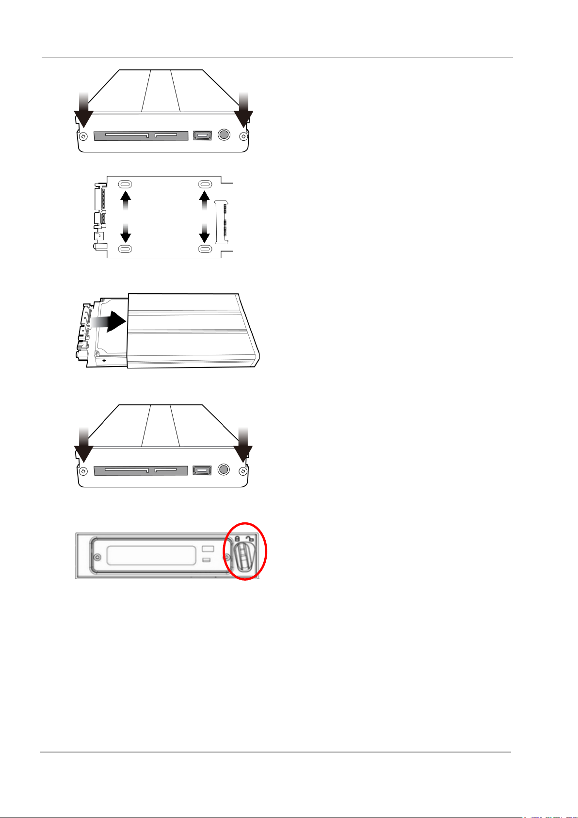
How to fit a SATA drive to the removable HE-3 enclosure
If your unit was delivered without a hard drive inserted, please follow the steps below to insert the hard
disk into an HE-3 drive enclosure.
7
HD / SD Recorder HDR-70
1. Remove the two screws on the back plate
of the HE-3 drive enclosure and manually
pull out the PCB.
2. Place a 2.5” SATA HDD on the PCB and
then turn it over so you can secure the
drive to the PCB by screwing the four
screws (supplied) into the holes as shown
in the diagram on the left.
3. Re-insert the PCB, with HDD mounted, into
the enclosure.
4. Re-secure the back plate of the enclosure
using the two screws removed earlier.
5. Push the removable HE-3 enclosure into
recorder as shown. Now move the locking
lever from right to left side to secure the
HE-3 in place.
6. You are now ready to switch the unit on.
7. New drives will be formatted within the recorder upon first use. The LCD Clip Status
display is shown once the recorder becomes available for set up and use.
8
HD / SD Recorder HDR-70
Power On / Off Button.
This is a soft power on / off button which powers the unit on from a
state of standby. The main power on /off switch is on the rear panel.
Display Panel.
Displays the status of the HDR-70. The display will show Bin Number,
time code, or if the Menu Button is pressed the Menu Display.
Menu Button.
This calls up the menu display which is navigated using the Previous /
Next Buttons.
Previous / Next Buttons.
These buttons navigate between recorded bins and menu options.
Record Mode Button.
Before recording make sure the Record Mode button is on/back lit.
Record Button.
To start recording press the Record and Play buttons together.
N.B. Unit will not record if no video signal is present.
Play / Pause Button.
Starts playback of a bin, or pauses playback of video – the status will
be displayed on the LCD Panel.
Fwd / Rew Buttons.
In playback mode these buttons will operate as Fast Forward and
Rewind Buttons.
Stop Button.
Stops playback or record functions.
Audio Level / Peak Meter.
The Audio Input Level LEDs show the audio input levels from the
selected incoming source. See pages 19 & 20 also.
Headphone Audio Monitoring.
Stereo mini jack plug for stereo headphone. The headphone audio
level is controlled by the volume [VOL] adjustment.
GEN-LOCK.
When this LED is on GEN-LOCK is present.
2.5" Removable HDD Slot.
Removable HE-3 HDD with SATA & USB interface connection to a
computer for fast copy & paste file transfer.
Connections and Controls
Front Panel
9

HD / SD Recorder HDR-70
XLR inputs and Outputs for Balanced Audio Connection.
Note: The recorder needs a video source in order to record files.
See page 20 also.
The GPI socket can be used for simple external control. The
recorder can accept pulse or level trigger inputs, which can trigger
record or playback and pause commands. See page 21 also.
RS-232/422 user selectable remote control (selection in menu).
See page 25 onwards.
Black Burst input/ output.
Can be used as a video reference source when synchronizing other
devices to the recorder.
Time Code input/ output.
The user can select the time code source as internal or external. Set
time code source to external when supplying an external Time Code
source to this input port.
HDMI Out Port.
Port for connecting to HDMI external devices.
HD- SDI input, output and loop-through connectors.
4:2:2 SDI Video data supports SMPTE 292M standard at 1.5Gbps.
SDI transfers professional level video signals and can connect to
long distance transmission systems.
DC In Socket. Connect the supplied 12V PSU to this socket. The
connection can be secured by screwing the outer fastening ring of
the DC In plug to this socket.
Power On/Off Switch.
Depress the dot side of the switch to turn the unit on. See front panel
soft power on / off button also.
Grounding Terminal.
When connecting this unit to any other component, make sure that it
is properly grounded by connecting this terminal to an appropriate
point. When connecting, use the socket and be sure to use wire with
a cross-sectional area of at least 1.0mm2.
Rear panel
10
HD / SD Recorder HDR-70
Rear Panel On / Off switch
Switches the power On / Off.
Front Panel Power button
Places the unit in standby mode or soft starts the unit.
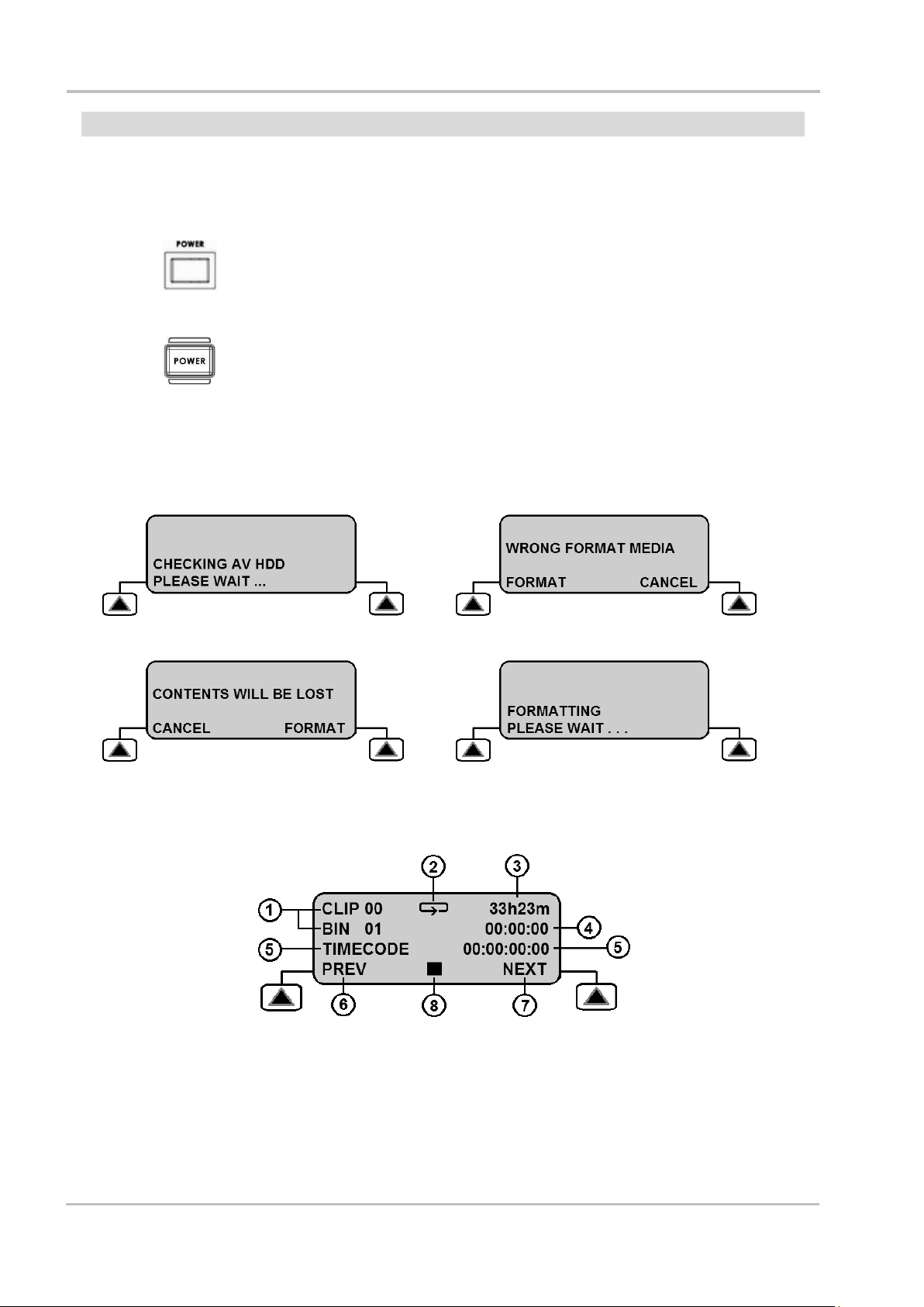
1. The drive is checked by the unit.
2. Choose the FORMAT option.
3. Confirm the FORMAT option.
4. The drive is now being made ready for
first use.
Switching the recorder On
Ensure the HDR-70 power supply is connected to the rear panel of the recorder and a HE-3 removable
drive enclosure is fitted and locked in place.
The HDR-70 has a power ON/OFF switch which is located on the rear panel. To turn the unit ON
depress the dot side of this switch.
If the unit is already switched ON at the rear panel but has not started it may be in standby mode. Press
the Power button on the front panel and LCD display should now become backlit.
Formatting a drive before first use
New HE-3 drive enclosures, as described on page 7, will need to be formatted in the recorder before
first use. The recorder’s LCD panel will display options as follows.
LCD Clip Status Display explained
1. Current Bin and Clip.
2. Loop playback indicator
If not present feature is OFF.
3. Remaining recording space in Hours
and Minutes.
4. Length of video within current Bin
[HH:MM:SS].
5. Current Time Code [HH:MM:SS:FF]
6. Function of left hand soft key.
7. Function of right hand soft key.
8. Record, Pause, STOP, FFWD,
FREV and Playback indicator.
11

HD / SD Recorder HDR-70
MAIN MENU
SUB MENUS
TOOL
ERASE THIS BIN
Erases the currently selected recording bin.
FORMAT MEDIA
Erases the whole contents of the drive and reformats it.
UPDATE FIRMWARE
See page 24 for further details on the update process.
UNLOCK MEDIA
Removes the write protection from the HE-3 drive.
FIRMWARE REVISION
Displays the current firmware detail.
SETUP
RECORD SETUP
See page 13 for further details
PLAY SETUP
See page 18 for further details
SYSTEM SETUP
See page 19 for further details
SAVE SETUP
RECALL SETUP
STATUS
LCD displays current recording bit rate and video format
Menu Button.
This calls up the Menu Display which is navigated using the
Previous and Next Buttons.
Previous / Next Buttons.
These buttons navigate between menu options or allow you to
choose an option value. A selected option will be confirmed by an
asterisk [*] character next to it. Chosen settings are also confirmed in
the status menu.
Menu Overview and Menu Navigation
Your HDR unit is a menu driven unit; there are several menus which are used to initially set up the unit. The
menu settings are non-volatile, so they are stored even when the unit is switched off. Many of these settings,
such as file type and bit rate, may only need to be set once. We will look at each menu in more detail, but
here is a quick overview of them.
The following front panel buttons are used to navigate the displayed menus and to change settings.
Menu button also acts as an exit button.
Press the Menu button once to exit the current option selection.
Press the Menu button again to exit the current menu level.
If there are no higher level menus then you will return to the Clip Status Display.
12

HD / SD Recorder HDR-70
MAIN MENU
SUB MENU 1
SUB MENU 2
TOOL
SETUP
STATUS
RECORD SETUP
PLAY SETUP
SET HD ENCODE FORMAT
SYSTEM SETUP
SET SD ENCODE FORMAT
SAVE SETUP
SET REC FILE TYPE
RECALL SETUP
SET SD ASPECT RATIO
TIME-LAPSE SET UP
PWR ON AUTO-RECORD
MAIN MENU
SUB MENU 1
SUB MENU 2
OPTION CHOICE
TOOL
SETUP
STATUS
RECORD SETUP
PLAY SETUP
SET HD ENCODE FORMAT
SYSTEM SETUP
SET SD ENCODE FORMAT
HD LONG GOP
SAVE SETUP
SET REC FILE TYPE
HD I-FRAME ONLY
RECALL SETUP
SET SD ASPECT RATIO
TIME-LAPSE SET UP
PWR ON AUTO-RECORD
Records at
HD LONG GOP options are:
4:2:0 10M LONG GOP
[ 10 Mbps ]
4:2:0 25M LONG GOP
[ 25 Mbps ]
4:2:2 35M LONG GOP
[ 35 Mbps ]
Selected setting confirmed
4:2:2 50M LONG GOP
[ 50 Mbps ]
with an asterisk *
4:2:2 65M LONG GOP
[ 65 Mbps ]
4:2:2 120M LONG GOP
[ 120 Mbps ]
HD I-FRAME ONLY options are:
4:2:2 100M I-ONLY
[ 100 Mbps ]
4:2:2 125M I-ONLY
[ 125 Mbps ]
Record Setup
This menu allows you to configure the HDR-70 so that the unit is ready to record the incoming video signal.
The options within this menu are:
SET HD ENCODE FORMAT
This option is used to choose the quality and bit rate of the recording to be made from a High Definition [SDI]
source. Options available are:
Note: The HDR-70 can only record the following HD-SDI input video formats.
1920x1080p 23.98 / 24
or 1920x1080i 50 / 59.94 / 60
or 1280x720p 50 / 59.94 / 60
13

HD / SD Recorder HDR-70
MAIN MENU
SUB MENU 1
SUB MENU 2
OPTION CHOICE
TOOL
SETUP
STATUS
RECORD SETUP
PLAY SETUP
SET HD ENCODE FORMAT
SYSTEM SETUP
SET SD ENCODE FORMAT
SAVE SETUP
SET REC FILE TYPE
SD LONG GOP
RECALL SETUP
SET SD ASPECT RATIO
SD I-FRAME ONLY
TIME-LAPSE SET UP
PWR ON AUTO-RECORD
Records at
SD LONG GOP options are:
4:2:0 8M LONG GOP
[ 8 Mbps ]
4:2:2 15M LONG GOP
[ 15 Mbps ]
Selected setting confirmed
4:2:2 30M LONG GOP
[ 30 Mbps ]
with an asterisk *
4:2:2 50M LONG GOP
[ 50 Mbps ]
SD I-FRAME ONLY options are:
4:2:2 25M I-ONLY
[ 25 Mbps ]
4:2:2 50M I-ONLY
[ 50 Mbps ]
SET SD ENCODE FORMAT
This option is used to choose the quality and bit rate of the recording to be made from a Standard Definition
[SDI] source. Options available are:
Note: The HDR-70 can only record PAL or NTSC SDI input video formats.
SET SD ASPECT RATIO
This option is used to set the aspect ratio of the recorded SD video.
Use the LCD menu path [MENU] > SETUP > RECORD SETUP > SET SD ASPECT RATIO
The options are 4:3 or 16:9. The selected choice is marked with an asterix[*] symbol.
It is recommended to have the recorder match the aspect ratio of the source equipment being recorded.
Note: If you choose the wrong aspect ratio people or objects within the recorded HDR-70 SD footage may be
changed to appear tall and thin or short and fat.
14

HD / SD Recorder HDR-70
Before recording
Before using your recorder, there are a few actions and options that should be considered.
Transfer old clips from the media
The HDR-70 is primarily a capture device, as
opposed to an archiving device, and it is best to
start out with a fresh HDR-70 HE-3 drive. If you
have video clips already recorded on the HE-3
drive, it is best to transfer them to a computer to
free up space on the HE-3 before starting the next
project.
See page 22 for further details.
FORMAT MEDIA
Use the LCD menu path [MENU] > TOOL >
FORMAT MEDIA to reformat the removable HE-3
drive and to erase un-wanted old clips ready for
the next recording session.
SET REC FILE TYPE
The HDR-70 can record HD or SD video to
an .MXF or .MOV file. Choose the file type which is
compatible with the edit software you plan to use
after the recording is made.
Use the LCD menu path [MENU] > SETUP >
RECORD SETUP > SET REC FILE TYPE to
confirm your choice.
Set the ENCODE FORMAT
The HDR-70 can record either Standard Definition
[SD] or High Definition [HD] video. It also offers a
choice of LONG GOP or I-FRAME ONLY
recording at various bit rates.
Use the LCD menu path [MENU] > SETUP >
RECORD SETUP > SET HD/SD ENCODE
FORMAT to confirm your choice.
See pages 13 and 14 for the available choices.
Select the AUDIO SOURCE
The HDR-70 can record digital audio already in
the SDI or HD-SDI video. Or it can record
analogue audio using the rear panel XLR audio
connections.
Use the LCD menu path [MENU] > SETUP >
SYSTEM SETUP > SELECT AUDIO SOURCE to
confirm your choice.
Select your time code source
Use the LCD menu path [MENU] > SETUP >
SYSTEM SETUP > SET TIME CODE to confirm
your choice from:
INTERNAL REC RUN
INTERNAL FREE RUN
EXTERNAL TC IN
When supplying external Time Code using the TC
IN BNC connection on the rear of the unit.
EXTERNAL SDI TC
When using the Time Code already embedded
within the SDI or HD-SDI video input.
If Time Code [TC] is not present or lost during
recording the LCD panel will flash the warning.
EXT TC LOST
Turn RECORD MODE on
Ensure the RECORD MODE button on the front
panel of the recorder is on or backlit.
If you try to start a recording with this button off
then the LCD panel will flash the warning.
GO REC MODE
15

HD / SD Recorder HDR-70
Recording
Before starting a new recording ensure the
recorder is set up correctly, please read pages 12
to 15 first.
Select an empty BIN in which to record
You can think of a BIN like a folder for holding a
single or group of related video CLIPS. The current
BIN and its contents, if any, are shown on the Clip
Status display, see page 11.
Use the right hand soft key labelled NEXT to move
to the next BIN. You will see the BIN number
change each time you select NEXT or PREVIOUS.
The video length stored within the selected BIN is
displayed in the format of Hours, Minutes and
Seconds [HH:MM:SS]. So a BIN showing 00:00:00
is empty and a BIN showing 01:35:24 is just over
one hour thirty five minutes long. For a new
recording select an empty BIN.
Note: A CLIP is automatically started at the
beginning of a BIN. If the BIN already contains
video the next CLIP is appended after the last
CLIP in the BIN. A clip can never be inserted
between other clips in a bin. The minimum length
of a CLIP is two seconds.
Recording
There are several ways of starting a record
session depending how the recorder is configured.
1) Manually by holding the REC button down
and pressing the PLAY button.
2) Using the Remote Serial interface. See the
command protocol at the rear of this manual.
3) Simple contact closure circuit using a switch,
contact or button wired to the GPI port on the
recorders rear panel. See page 21 for more
information.
Note: If power is interrupted while recording, up to
two seconds of the current video CLIP may be lost.
Record Pause
There are several ways of pausing a record
session depending how the recorder is configured.
1) Manually by pressing the PLAY button.
Press the PLAY button again to resume
recording.
2) Using the Remote Serial interface. See the
command protocol at the rear of this manual.
3) Simple contact closure circuit using a switch,
contact or button wired to the GPI port on the
recorders rear panel. See page 21 for more
information.
Note: Each time the recording is resumed a new
CLIP will be created within the same recording BIN.
A maximum of 99 CLIPS can be created within a
single BIN. The minimum length of a CLIP is
two seconds.
Record Stop
There are several ways to stop a record session
depending how the recorder is configured.
1) Manually by pressing the STOP button.
2) Using the Remote Serial interface. See the
command protocol at the rear of this manual.
3) When using the GPI port on the recorder first
put the recorder into record pause mode then
press the STOP button on the recorder as
you would do if recording manually. See page
21 for more information
16

HD / SD Recorder HDR-70
Special Record Functions
Time lapse recording
Time lapse can be a useful I-FRAME only
recording option when studying changes in a
subject over a long period of time such as in large
scale building projects or scientific studies or even
to create artistic animations.
Use the LCD menu path [MENU] > SETUP >
RECORD SETUP > TIME-LAPSE SETUP to
confirm your choice from:
TIME LAPSE ON/OFF
If the setting is OFF then normal recording mode
and settings will be used.
If the setting is ON then an I-Frame only recording
mode should be chosen and the next record
session will be based on the following settings.
SET TIME LAPSE FRAME
This setting controls the amount frames of video
captured when the time lapse cycle/interval point is
reached. From 1 up to 15 frames can be captured.
Once the required value is selected, press MENU
to exit this setting.
SET TIME LAPSE CYCLE
This setting defines the amount/cycle of time
elapsed between video being captured. This can
be any time value between 1 second and 59
minutes 59 seconds.
Once the required value is selected, press MENU
to exit this setting.
Example:
If SET TIMELAPSE FRAME is set to 2 frames and
SET TIMELAPSE CYCLE is set to 15 seconds
then the HDR-70 will display:
CYCLE: 02 FRM / 15 S
So 2 frames [FRM] of video will be added to the
current BIN after each 15 second [S] cycle until the
recording session is stopped.
Note: This mode is saved when power is
interrupted. This process resumes if power and
video are both restored. See Power On Auto
Record function also.
Note: A new clip is only created at the beginning
of a time lapse recording.
Power on auto record
If this option is enabled when the unit is powered
on the recorder will begin recording immediately.
The current BIN and the last record setup used
before the recorder was switched off will be used
for the next recording.
17

Playback
Select a recorded BIN to Play back
You can think of a video BIN as being like a folder
for holding a single or group of related video
CLIPS. The current BIN and its contents, if any,
are shown on the Clip Status display,
See page 11.
Use the right hand soft key labelled NEXT to move
to the next BIN. You will see the BIN number
change each time you select NEXT or PREVIOUS.
The video length stored within the current BIN is
also displayed in the format of Hours, Minutes,
Seconds [HH:MM:SS]. So a BIN showing 00:00:00
is empty and a BIN showing 01:35:24 is just over
one hour thirty five minutes long.
Before pressing the PLAY button, first select the
correct BIN where the required video has been
recorded.
Note: If you select an empty BIN then nothing will
happen when you press the PLAY button.
Play back
There are several ways of starting play back
depending how the recorder is configured.
1) Manually by using the PLAY button.
2) Using the Remote Serial interface. See
the command protocol at the rear of this
manual.
3) Simple contact closure circuit using a
switch, contact or button wired to the GPI
port on the recorders rear panel. See
page 21 for more information.
When in playback mode the keys FREV and
FFWD will change the playback/shuttle speed to
3x, 6x, 9x or 12x fast reverse and fast forward.
Repeatedly pressing a soft key will cause the
playback to go faster in the chosen direction up to
12x speed. A speed other than 1x is displayed in
the bottom line of the LCD panel.
To return to normal play press the Play/Play Pause
button.
Playback in BIN or CLIP centric mode
Depending on how the Play Setup menu options
are set, the recorder will either play back ONLY
the last CLIP within the current BIN or play back
ALL CLIPS within the selected BIN.
When the BIN Centric Mode is enabled [ON] the
play back function plays ALL the CLIPS recorded
in the current BIN.
When the BIN Centric Mode is disabled [OFF] the
play back function only plays the current or last
CLIP recorded within the selected BIN.
Use the LCD menu path [MENU] > SETUP >
PLAY SETUP > SET PLAY CENTRIC
Note that the current selection BIN or CLIP will be
marked with an asterisk [*].
Loop Play
When loop play is enabled and the last frame of
the clip is reached the unit will start playing over
from the first frame instantly.
Use the LCD menu path [MENU] > SETUP >
PLAY SETUP > SET LOOP PLAY
Power on Auto Play
When this option is enabled the recorder will
immediately begin playing back the current BIN or
CLIP when first powered up.
Use the LCD menu path [MENU] > SETUP >
PLAY SETUP > POWER ON AUTO PLAY
18

System Set Up
MAIN MENU
SUB MENU 1
SUB MENU 2
TOOL
SETUP
STATUS
RECORD SETUP
PLAY SETUP
SYSTEM SETUP
SAVE SETUP
SET AUDIO MONITOR
See below section.
RECALL SETUP
SELECT AUDIO SOURCE
See page 20.
SET TIME CODE
See page 15.
SET GPI
See page 21.
SET REMOTE INTERFACE
See page 25.
SET BUZZER
See page 25.
SET LONG TIME STOP
See page 25.
DATE & TIME SET UP
See page 25.
The SYSTEM SETUP menu has the following options
Set Audio Monitor
This LCD menu option allows the user to choose
which audio channel pair to monitor with the front
panel LED audio peak meter and the headphone
socket.
LCD Audio Peak meter
Whilst recording or playing back a CLIP, the front
panel RECORD button can be pressed. This
changes the LCD panel from the Clip Status view
to an LCD Audio Peak Meter view.
Use the LCD menu path [MENU] > SETUP >
SYSTEM SETUP > SET AUDIO MONITOR
The default setting is AUDIO CHANNEL 1 & 2.
There are four stereo pair monitoring options:
AUDIO CHANNEL 1 & 2, or
AUDIO CHANNEL 3 & 4, or
AUDIO CHANNEL 5 & 6, or
AUDIO CHANNEL 7 & 8
The current selection will be marked with an
asterisk [*].
The default setting is AUDIO CHANNEL 1 & 2.
Pressing the record button will cycle the LCD
panel view through Audio Channels 1 to 4, Audio
Channels 5 to 8 and then back to Clip Status view
again.
If there are no audio channels present the bars will
not move on the LCD display. If audio is present
then the level bars will move for that channel and a
dBFS value will be shown alongside.
19

Select Audio Source
Use the LCD menu path [MENU] > SETUP > SYSTEM SETUP > SELECT AUDIO SOURCE
This recorder can accept audio signals which are already embedded in the SDI / HD-SDI video input. The
recorder can alternatively accept analogue audio from the rear panel Balanced XLR audio inputs.
If SDI / HD-SDI embedded audio is selected, the audio channels recorded will match the SDI input.
If Analogue XLR audio is selected, this audio will be recorded into AUDIO CHANNEL 1 & 2 only.
20

HD / SD Recorder HDR-70
GPI Control
GPI Trigger cabling and circuit
The recorder has a GPI socket on its rear panel. The
GPI circuit runs on less than 5V DC. This power is
supplied by the recorders GPI port. You will need to
manufacture a GPI trigger cable to create a simple
‘contact on closure’ button or similar trigger.
Depending on the settings of the recorder and the GPI
menu option this unit can be configured to Record /
Record Pause or Play / Play Pause with the current
video BIN.
SET GPI
Use the LCD menu path [MENU] > SET UP >
SYSTEM SET UP > SET GPI.
You can then make a choice between the PULSE or
LEVEL trigger. The selected choice is marked with an
asterisk [*].
PULSE trigger Record process
Using the Clip Status Display and soft keys, select an
empty video BIN. Make sure the source device is
connected and working and the target file type on the
recorder has been chosen. Press and hold in the Record
button on the front panel and then press the Play button.
This should start the record process. The button on the
connected GPI cabling is then pressed forcing the unit
into record pause mode. The unit is then ready to
activate record on the next press of the contact closure
button. Each time the recorder starts recording a new
clip will be added to the bin [ Max 99 CLIPS per BIN ].
Press the stop button on the front panel of the recorder
to end the recording process.
LEVEL trigger Record process
Using the Clip Status Display and soft keys, select an
empty video BIN. Make sure the source device is
connected and working and the target file type on the
recorder has been chosen. Press and hold in the Record
button on the front panel and then press the Play button.
This should start the record process. The button on the
connected GPI cabling is then pressed forcing the unit
into record pause mode for the length of the press.
However, when the button is released the recording
process starts again. Each time the recorder starts
recording a new clip will be added to the bin [ Max 99
CLIPS per BIN ]. Press the stop button on the front
panel of the recorder to end the recording process.
The contact closure button may be working in the
opposite way to the type of action you want to perform.
A mechanical change to the GPI contact closure trigger
should fix this. (Example: when pressed down the
circuit is broken and recording starts. When released the
contact is made causing the pause action.)
Note: You may a have a couple of seconds footage at
the beginning of the bin that you may wish to remove
later once the footage is transferred to a computer for
editing.
PULSE trigger Playback process
Using the Clip Status Display and soft keys, select a
pre-recorded video BIN. Make sure the output device
/monitor is connected and working with the recorder.
Press in the Play button on the recorder’s front panel.
This should start the playback. The button on the
connected GPI cabling is then pressed forcing the unit
into play pause mode. The unit is then ready to playback
from this point on the next press of the contact closure
button. Press the stop button on the front panel of the
recorder to end playback of the video.
LEVEL trigger Playback process
Using the Clip Status Display and soft keys, select a
pre-recorded video BIN. Make sure the output
device/monitor is connected and working with the
recorder. Press in the Play button on the recorder’s front
panel. This should start the playback. The button on the
connected GPI cabling is then pressed forcing the unit
into play pause mode for the length of the press.
However, when the button is released the playback
starts again. Press the stop button on the front panel of
the recorder to end playback of the video.
The contact closure button may be working in the
opposite way to the type of action you want to perform.
A mechanical change to the GPI contact closure trigger
should fix this. (Example: when pressed down the
circuit is broken and recording starts. When released the
contact is made causing the pause action.)
21

Transferring files to a computer
Recorder File System limitations
This recorders NTFS format is fully compatible
with PCs and is read compatible with Macs. Its
main advantage is that results in one large file per
recording.
Note: Some editing software packages cannot
accept video file sizes greater than 40GB, make
sure your edit software is not affected if you plan
on shooting one long continuous take greater than
this.
File Organization
All bins that contain video will appear to the
computer as folders named BINxx. Where xx
represents the BIN number ranging from 01 to 99.
Inside each BIN folder, each clip will be
represented as a separate file with an extension
name like .MXF .MOV depending on the setting
chosen prior to recording.
Each file will be named BxxCnn where xx
represents the BIN number; nn represents the
CLIP number ranging from 01 to 99.
Mounting the HE-3 drive enclosure to a Computer
Move the drive lock lever to the right to unlock the HE-3 drive from the recorder. Push the HE-3 into the
unit and when released it will pop out a few centimetres. Gently pull the drive enclosure clear of the
recorder. You may feel some slight resistance as the drive disconnects internally – this is normal.
The removable HE-3 drive enclosure has a mini USB connector on its rear panel; this can provide power to
the HDD, as well as allow the exchange of data.
Note: With some PCs and Laptops the USB bus power may not be enough to power the drive.
Connect the supplied mini USB to USB A cable to the HE-3 drive, and connect the double lead to your
computer or Laptop. If the drive does not power up correctly – connect the second USB connector to the
computer as well as the first.
22

HD / SD Recorder HDR-70
The drive will appear on the computer as a volume called HDR-SERIES.
Safely dis-mounting the HE-3 drive from a computer
In order not to cause damage to the spinning drive within the HE-3 drive do not immediately disconnect the
USB 2.0 cable straight away. Instead use your Computer’s drive dis-mounting process first and then
physically remove the HE-3 drive after this process has been completed.
Windows 7 Apple Mac OSX
Windows computers have a Safely Remove Hardware process seen in the System Tray area and Apple
Mac computers have an Eject Drive/Hardware process in the Devices area.
23

HD / SD Recorder HDR-70
Updating the Firmware
From time to time Datavideo may release new firmware to fix reported bugs in the current recorder
firmware or to add a new feature. Customers can update the recorder firmware themselves if they wish or
they can contact their local dealer or reseller for assistance should they prefer this method.
This section describes the firmware update process for the recorder, if you have all the items required it
should take approximately 20 minutes total time to complete.
Please contact your local dealer or Datavideo office for the latest firmware update flash file.
WARNING: Once started the update process and power should not be interrupted in any way as this
could result in a non-responsive unit.
To update the firmware:
1. Check firmware version.
Press the MENU button, browse to TOOL using the NEXT button and then press ENTER to select.
Locate FIRMWARE REVISION in TOOL and press ENTER to show the current firmware version.
If your CODEC version number starts with FFF, contact your Datavideo distributors or sales
representatives for device firmware upgrade procedure.
If your CODEC version number starts with 130, simply follow the procedure below to update the
firmware.
2. Follow the link below to download firmware from Datavideo’s official website
www.datavideo.com Products Recorders HDR-60 Downloads Latest Firmware
After unzipping the downloaded file, you should be able to see two bin files in the “Disk Update” folder.
If CODEC version is NOT D10B, use
“HDR70_flash_C3DB_host_C215_codec_C4_ifpga_32_ALL.bin” to update the firmware.
If CODEC version is D10B, use “HDR70_flash_C3DB_host_C215_codec_C4_ifpga_32_no_NTT.bin”
to update the firmware.
3. Use a USB cable to connect the hard disk (HE-3) removed from the HDR-60/70 to the PC containing the
downloaded firmware file.
4. Rename the latest firmware file to “flash.bin” before copying it to the hard disk.
5. Re-insert the hard disk containing the latest firmware file to the HDR-60/70, press the MENU button and
select “Upgrade Firmware” in the TOOL option.
6. If the firmware upgrade is successful, the REC, CODEC and HOST REV version numbers displayed on
the HDR-60/70 should be the same as the versions recorded in release notes.
WARNING: After the firmware update is complete, the firmware file must be removed from the hard
drive as failure to do so may result in errors while the HDR-60/70 is recording.
24

HD / SD Recorder HDR-70
MAIN MENU
SUB MENU 1
SUB MENU 2
USER CHOICE
TOOL
SETUP
STATUS
RECORD SETUP
PLAY SETUP
SYSTEM SETUP
SAVE SETUP
SET AUDIO MONITOR
RECALL SETUP
SELECT AUDIO SOURCE
Selected setting confirmed
SET TIME CODE
with an asterisk *
SET GPI
SET REMOTE INTERFACE
RS232 or RS422
SET BUZZER
SET LONG TIME STOP
DATE & TIME SET UP
Set Buzzer
Use the LCD menu path [MENU] > SET UP > SYSTEM SET UP > SET BUZZER
This setting when enabled or selected provides the user with an alarm feature if there is an “un-recoverable”
defect detected in the HDR-70.
Set Long Time Stop
Use the LCD menu path [MENU] > SET UP > SYSTEM SET UP > SET LONGTIME STOP
This setting changes the operation of the stop button. When enabled or selected the front panel STOP
button must be held in for longer in order to stop the recording or playback in progress. This eliminates the
chance of the user accidently performing a stop action when using the other front panel controls.
Date and Time Setup
Use the LCD menu path [MENU] > SET UP > SYSTEM SET UP > DATE & TIME SET UP
Date and Time meta data can be added to recorded files when this menu option is used.
FFWD moves the cursor to the next Date or Time field.
FREV moves the cursor to the previous Date or Time field.
PLAY/PAUSE increases the value of the current field.
RECORD decreases the value of the current field.
Once complete use [MENU] to exit.
Set Remote Interface
Use the LCD menu path below to choose which protocol will be used to control or talk to the recorder.
25

HD / SD Recorder HDR-70
9 Pin D-Sub
Controller
Recorder
9 Pin D-Sub
Pin 2 (Rx)
Pin 3 (Rx)
Pin 3 (Tx)
Pin 2 (Tx)
Pin 5 (GND)
Pin 5 (GND)
Command
Name
Response
Name
System Control
00h, 11h, 11h
Device Type Request
12h, 11h, 00h, 00h, 23h
Device Type
00h, F1h, F1h
Next Bin
10h, 01h, 11h
ACK
00h, F2h, F2h
Previous Bin
10h, 01h, 11h
ACK
02h, F5h, 08h, 00h, FFh
Disable Loop Play
10h, 01h, 11h
ACK
02h, F5h, 08h, 01h, 00h
Enable Loop Play
10h, 01h, 11h
ACK
01h, F0h, nn, csum
Select Bin(1~99)
10h, 01h, 11h
ACK
RS-232 Controller Command Set
Connector Pin Assignment
Interface : 9 pin D-Sub female to 9 pin D-Sub female
The pin assignment of the Controller and recorder is shown in the following table:
Communication Format
Mode: No synchronization
Character Length: 1 start bit + 8 data bits + 1 parity bit + 1 stop bit
Data Rate: 38,400 Baud
Parity: Odd
Command Format
CMD1, CMD2, Data bytes …., Checksum byte
A Command is made up of two address bytes, CMD1 and CMD2, a variable number of Data bytes (Data
from 0 up to 15) and a Checksum byte. The Checksum byte is the modulo 256 sum of all preceding bytes.
The most significant nibble of the CMD1 byte represents the command group. The least significant nibble
represents the number of Data bytes to follow the CMD2 byte.
Command Protocol
CMD1, CMD2, Data bytes …., Checksum byte
Response: ACK [10h, 01h, 11h]
Other than the sense command, the unit will respond to all commands affirmatively by sending a three byte
acknowledgement (ACK) if the Checksum is valid. If the Checksum is not valid, the Recorder will ignore the
command. Most commands will be responded to within 8 msec. However, a PLAY command from an idle
state will result in response delay of up to 700 msec. During this busy time, all commands will be ignored.
Summary List of Commands
26

HD / SD Recorder HDR-70
Command
Name
Response
Name
61h, 20h, 0Fh, 90h
Status Sense
7Fh, 20h, [15 bytes], csum
Status
61h, 0Dh, 04h, 72h
Current Frame Offset
74h, 0Dh, [4 bytes] , csum
Frame Offset
61h, F1h, 01h, 53h
Current Bin
61h, 00h, nn, csum
Bin Number
System Control
00h, 11h Device Type request
The response is 00, 00 indicating Quick Capture
00h, F1h Next Bin
When this command is issued from the Idle state the next bin is selected. If the present bin is 99 then the
next bin is 1.
00h, F2h Previous Bin
When this command is issued from the Idle state the previous bin is selected. If the present bin is 1 then
the next bin is 99.
02h, F5h, 08h, 00h, FFh Disable Loop Play
When this command is issued from the Idle state the Loop Play feature is disabled. Loop Play is where the
the last play command is repeated from its beginning when the end is reached.
02h, F5h, 08h, 01h, 00h Enable Loop Play
When this command is issued from the Idle state the Loop Play feature is enabled. Loop Play is where the
the last play command is repeated from its beginning when the end is reached.
01h, F0h, XX, csum Select Bin XX
When this command is issued from the Idle state bin XX is selected. XX varies between 1 and 99. Illegal
bins are ignored.
02h, F3h, 01h, XX, csum Select and Empty Bin XX
When this command is issued from the Idle state bin XX is selected and all of its content is permanently
deleted. XX varies between 1 and 99. Illegal bins are ignored.
Sense Request
61h, 0Ch, 04h, 71h Current Time Sense
Requests the Time code data. The unit responds with 4 bytes indicating the present time code in BinaryCoded-Decimal. The first byte holds the frame number, the second byte holds the seconds, the third the
minutes and the fourth the hour. In the play state, the time code returned is the time associated with the
current frame being played, in the record state, the time code returned represents the elapsed time
recorded in the present bin.
24h, F1h, nn Play Offset nn
Frame Offset number nn is played. The number nn is made up of 4 binary encoded bytes and sent out with
the least significant byte first. This command may be issued from the idle state or any other Play state.
Note: Frame Offset are represented in absolute frame numbers where the first frame of the bin is 0.
24h, F2h, nn Play from Offset nn
Content of the present bin is played at 1x speed starting at Frame Offset nn. This command may be issued
from the Idle state or any other Play state.
24h, F3h, bb, nn Select Bin and Play Offset
Bin number bb is selected and Frame Offset number nn is played. This command may be issued from the
idle state or any other Play state.
27

HD / SD Recorder HDR-70
24h, F4h, bb, nn Select Bin and Play from Offset
Content of the bin number bb is played at 1x speed starting at Frame Offset nn. This command may be
issued from the idle state or any other Play state.
24h, F5h, nn Play to Offset nn
Content of the present bin is played at 1x speed starting from present Frame Offset until Frame Offset nn
at which point it pauses. Frame Offset nn is 4 bytes and starts with the LSB. This command may be issued
from the idle state or any other Play state.
25h, F5h, bb, nn Select Bin and Play to Offset
Content of the bin number bb is played at 1x speed starting at Frame Offset 0 to Frame Offset nn then
pause. Frame Offset nn is 4 bytes and starts with the LSB. This command may be issued from the idle
state or any other Play state.
29h, F5h, bb, nn, ee Select Bin and Play from Offset to Offset
Content of the bin number bb is played at 1x speed starting at Frame Offset nn to Frame Offset ee then
pause. Frame Offsets nn and ee are 4 bytes and start with the LSB.
Transport Control
20h, 00h, 20h Stop
The unit enters the idle state. In the A2D, the outputs reflect the video source as selected by the Front
Panel.
20h, 01h, 21h Play
Content of the present bin is played at 1x speed. This command may be issued from the idle state or any
other Play state.
20h, 02h, 22h Record
The video is recorded from the selected source onto the current Bin. This command may be issued only
from the idle state.
20h, 10h, 30h Fast Forward
A play state where video is played at the highest speed of 32x in the forward direction.
20h, 20h, 40h Fast Rewind
A play state where video is played at the highest speed of 32x in the reverse direction.
NOTE: When receiving one of the following commands (JOG, VARIABLE or SHUTTLE ), the unit will play
forward or backward according to the speed data.
The first data byte may only be a maximum of 80:
Play Speed=10(nn/32-2)
Note that setting nn to 0 will result in pausing the unit.
21h, 11h, nnh Jog Forward
21h, 12h, nnh Variable Forward
21h, 13h, nnh Shuttle Forward
A Play state where video is played at the commanded play speed as described above in the forward
direction. Note: Setting the speed to 0 causes the play to pause.
21h, 21h, nnh Jog Reverse
21h, 22h, nnh Variable Reverse
21h, 23h, nnh Shuttle Reverse
A Play state where video is played at the commanded play speed as described above in the reverse
direction. Note: Setting the speed to 0 causes the play to pause.
21h, F0h, nnh Select Bin and Play
Content of the bin number nn is played at 1x speed from the beginning. This command may be issued from
the idle state or any other Play state
28

HD / SD Recorder HDR-70
Command
Name
Response Data
Common Transport Control
20h, 00h, 20h
Stop
10h, 01h, 11h
20h, 01h, 21h
Play
10h, 01h, 11h
20h, 02h, 22h
Record
10h, 01h, 11h
Common Trick Play
21h, 11h,, 00h, 32h
Play Pause
10h, 01h, 11h
20h, 10h, 30h
Fast Forward
10h, 01h, 11h
21h, 13h,, nn, csum
Shuttle Forward
10h, 01h, 11h
20h, 15h, 35h
Jump Forward
10h, 01h, 11h
20h, 20h, 40h
Fast Rewind
10h, 01h, 11h
21h, 23h,, nn, csum
Shuttle Reverse
10h, 01h, 11h
20h, 25h, 45h
Jump Reverse
10h, 01h, 11h
Vendor Unique Control
01h, F0h, nn, csum
Select Bin(1~99)
10h, 01h, 11h
00h, F1h, F1h
Next Bin
10h, 01h, 11h
00h, F2h, F2h
Previous Bin
10h, 01h, 11h
Common System Control
00h, 11h, 11h
Device Type Request
12h, 11h, 00h, 00h, 23h
Vendor Unique Control (External)
02h, F3h, 01h, nn, csum
Select Bin & Delete(1~99)
10h, 01h, 11h
02h, F3h, 02h, xx, csum
Idle mode select Record/Play
10h, 01h, 11h
02h, F3h, 02h, 00h, F7h
Play Mode
10h, 01h, 11h
02h, F3h, 02h, 01h, F8h
Recorder Mode
10h, 01h, 11h
02h, F3h, 04h, xx, csum
Audio Input Select
10h, 01h, 11h
02h, F3h, 04h, 00h, F9h
Audio Input :SDI
10h, 01h, 11h
02h, F3h, 04h, 01h, FAh
Audio Input :XLR
10h, 01h, 11h
02h, F3h, 05h, xx, csum
HD Rec Format (I-only/LGOP)
10h, 01h, 11h
02h, F3h, 05h, 00h, FAh
HD Long-GOP
10h, 01h, 11h
02h, F3h, 05h, 01h, FBh
HD I frame only
10h, 01h, 11h
02h, F3h, 06h, xx, csum
Bit Rate Select (HD)
10h, 01h, 11h
LGOP:10/25/35/50/65/120
10h, 01h, 11h
I-only:100/125
10h, 01h, 11h
02h, F3h, 07h, xx, csum
Bit Rate Select (SD)
10h, 01h, 11h
LGOP:8/15/30/50
10h, 01h, 11h
I-only:25/50
10h, 01h, 11h
02h, F3h, 09h, xx, csum
SD Aspect 4x3 or 16x9
10h, 01h, 11h
02h, F3h, 09h, 00h, FEh
SD Aspect :4x3
10h, 01h, 11h
02h, F3h, 09h, 01h, FFh
SD Aspect :16x9
10h, 01h, 11h
02h, F3h, 0Ah, xx, csum
SD Rec Format (I-only/LGOP)
10h, 01h, 11h
02h, F3h, 0Ah, 00h, FFh
SD Long-GOP
10h, 01h, 11h
02h, F3h, 0Ah, 01h, 00h
SD I frame only
10h, 01h, 11h
02h, F5h, 08, xx, csum
Loop Play control
10h, 01h, 11h
02h, F5h, 08h, 00h, FFh
Disable Loop Play
10h, 01h, 11h
02h, F5h, 08h, 01h, 00h
Enable Loop Play
10h, 01h, 11h
Vender Unique System Control
21h, F1h, 00h, 12h
Next (Right key)
10h, 01h, 11h
21h, F1h, 01h, 13h
Next Bin
10h, 01h, 11h
21h, F1h, 02h, 14h
Next Clip
10h, 01h, 11h
21h, F2h, 00h, 13h
Previous (Left Key)
10h, 01h, 11h
21h, F2h, 01h, 14h
Previous Bin
10h, 01h, 11h
21h, F2h, 02h, 15h
Previous Clip
10h, 01h, 11h
Vendor Unique System
Commands (External)
01h, F6h, 00, F7h
Make Media File (Unlock Media)
10h, 01h, 11h
01h, F6h, 01, F8h
Empty Current Bin
10h, 01h, 11h
29

HD / SD Recorder HDR-70
Command
Name
Response Data
01h, F6h, 02, F9h
Empty All (Format Media)
10h, 01h, 11h
Sense Control
61h, 0Ch, 04h, 71h
Start Time code Sense
74h, 00h, TC(3:0), csum
61h, 0Dh, 04h, 72h
Current Frame Offset
74h, 0Dh, [4 bytes] , csum
61h, 20h, 0Fh, 90h
Status Sense
7Fh, 20h, [15 bytes], csum
Vendor Unique Sense Control
62h, F2h, 05h, 00h, 59h
Firmware Revision Sense (Recorder)
79h, F2h, 05h, 00h, [7 bytes] , csum
62h, F2h, 05h, 01h, 5Ah
Firmware Revision Sense (Host)
79h, F2h, 05h, 01h, [7 bytes] , csum
62h, F2h, 05h, 02h, 5Bh
Firmware Revision Sense (CODEC)
79h, F2h, 05h, 02h, [7 bytes] , csum
10h
01h
csum
11h
12h
Data
byte
csum
Bit-7
Bit-6
Bit-5
Bit-4
Bit-3
Bit-2
Bit-1
Bit-0
0 0 0
Parity
Error
INHIBIT
CHECKSUM
ERROR
0
UNDEFINED
COMMAND
12h
11h
Device
byte1
Device
byte2
csum
nn
speed
Command Forward
Command Reverse
62h
12X
21h 13h 62h 96h
21h 23h 62h A6h
5E h
9X
21h 13h 5E h 92h
21h 23h 5E h A2h
58 h
6X
21h 13h 58h 8Ch
21h 23h 58h 9Ch
4F h
3X
21h 13h 4F h 83h
21h 23h 4F h 93h
40h
1X
21h 13h 40h 74h
21h 23h 40h 84h
3. Return Data
10h 01h : ACK
When a command from the CONTROLLER is received normally, the DEVICE returns this command as
acknowledgment
11h 12h : NAK
When a communication error is detected or an undefined COMMAND is received, the DEVICE returns this
command as not-acknowledgment. Bit-7 to Bit-0 of Data byte will be set in accordance with the contents.
[Data byte]
12h 11h : DEVICE TYTPE
The“00h, 11h, 11h : DEVICE TYPE REQUEST” command is used for asking the specifications of the HDR60/70 used as DEVICE. When the DEVICE receives this command, it attaches 2-bytes specification data
to “12h 11h : DEVICE TYPE” and sends the information to the CONTROLLER.
HDR-60/70: 12h , 11h, 00h, 00h, csum,
4. Return Data
21h 13h nn csum : Shuttle Forward
21h 23h nn csum : Shuttle Reverse
5. Return Data
21h, F1h, 02h, 14h : Next Clip
21h, F2h, 02h, 15h : Previous Clip
Note: Only can do clip-change at play-pause
30

HD / SD Recorder HDR-70
Status
Byte
Bit 7
Bit 6
Bit 5
Bit 4
Bit 3
Bit 2
Bit 1
Bit 0
0
Busy
0
Cartridge
Out
0 0 0
0
Local
enable
1
0 0 Stop
0
Rewind
Fast Forward
Record
Play
2
0 0 0 0
Reverse
Still
(Pause)
0
3
0 0 0 0 0
0
Video
in
0
4
1 0 0 0 1 0 0
0 5 0 0 0 0 0 0
0 6 0 0 0 0 0 0 0
0 7 0 0 0 0 0 0 0
0
8
0
0
Near End of
Disk (panic
mode)
End of
disk
0 0 0
0
9
0 0 0 0 0 0 0
0
10
BIN7
BIN6
BIN5
BIN4
BIN3
BIN2
BIN1
BIN0
11
File
Length
byte 0
FL0
FL0
FL0
FL0
FL0
FL0
FL0
12
Length
Byte 1
FL1
FL1
FL1
FL1
FL1
FL1
FL1
13
Length
Byte 2
FL2
FL2
FL2
FL2
FL2
FL2
FL2
14
Length
Byte 3
FL3
FL3
FL3
FL3
FL3
FL3
FL3
6. Firmware Revision Sense Data[7bytes]
Firmware Revision Sense (Recorder)
Byte[0]: ROM
Byte [1]: FW Major
Byte [2]: FW Minor
Byte [3]: File System
Byte [4]: FPGA
Byte [5]: RBF
Byte [6]: ESP
Firmware Revision Sense (Host)
Byte [0]: FW Major
Byte [1]: FW Minor
Byte [2]: Control CMD Major
Byte [3]: Control CMD Minor
Byte [4]: Bootloader Minor
Byte [5]: 0x00
Byte [6]: 0x00
Firmware Revision Sense (Codec)
Byte [0]: Codec Bootloader Major
Byte [1]: Codec Bootloader Minor
Byte [2]: Codec Host Major
Byte [3]: Codec Host Minor
Byte [4]: Codec Major
Byte [5]: Codec Minor
Byte [6]: 0x00
7. Status Sense Control Command Response Bytes
31

HD / SD Recorder HDR-70
Revision History:
Revision 00 30(01/10/2014)
1. Add HD long GOP 50Mb
2. Add Trick play command
3. Add select clip command
4. Busy bit will be set at change status
5. Add Parity error bit
Revision 00 28(10/31/2013)
Revision 00 27(10/29/2013)
Revision 00 02 (08/25/2013)
Revised on 11/14/2012
32

HD / SD Recorder HDR-70
Unit: mm
Depth [Front to Rear] : 288.4mm
Width : 481mm / Standard 19” with rack ears
Height : 49mm / Standard 1RU without feet
Gross weight [Packed] : 4.86 Kg / 10.71 lbs
Nett Weight [Unit only] : 3.85 Kg / 8.48 lbs
Dimensions & Weight
33

HD / SD Recorder HDR-70
Video Standard
HD & SD
Video Format
1080p 23.97/24Hz ,
1080i 50/59.94/60Hz ,
720p 50/59.94/60Hz ,
576i 50Hz, 480i 59.94Hz
Supported Video
Input Signal
1x SDI
Monitoring/
Playback output
1x SDI (input loop thru)
1x HDMI, 1x SDI (Out)
Analog Audio Input
& Audio Output
2x Balanced XLR
(Stereo pair)
Embedded Audio
Both In & Out (8-CH on SDI/HDMI)
Storage Medium
2.5” Hard Drive / SSD*, Max capacity 1TB
Estimated Record
Time (min per 10GB)
SD: 19 (50Mbps) ~ 70 (8Mbps)
HD: 8 (125Mbps) ~ 62 (10Mbps)
How to Retrieve
Recorded Content
Removable Hard Drive / SSD,
transfer data via USB2.0
Storage File System
NTFS (read only)
Recorded File
Format
MXF OP1A, MOV
Video Recording
Bit Rate/ Color
Sampling
MPEG2 Long GOP HD:
1. 10Mbps 4:2:0 1440x1080/1280x720,
2. 25Mbps 4:2:0 1440x1080/1280x720,
3. 35Mbps 4:2:2 1920x1080/1280x720,
4. 50Mbps 4:2:2 1920x1080/1280x720,
5. 65Mbps 4:2:2 1920x1080/1280x720,
6. 120Mbps 4:2:2 1920x1080/1280x720,
MPEG2 Long GOP SD
1. 8Mbps 4:2:0 720x480/720x576
2. 15Mbps 4:2:2 720x480/720x576
3. 30Mbps 4:2:2 720x480/720x576
4. 50Mbps 4:2:2 720x480/720x576
MPEG2 I-Frame Only HD
1. 80Mbps 4:2:2 1920x1080/1280x720
2. 100Mbps 4:2:2 1920x1080/1280x720
3. 125Mbps 4:2:2 1920x1080/1280x720
MPEG2 I-Frame Only SD
1. 25Mbps 4:2:2 720x480/720x576
2. 50Mbps 4:2:2 720x480/720x576
Audio Recording
Format
Uncompressed PCM
Sampling rate 48KHz 24bit
Time code in/out
Yes
Specifications
34

HD / SD Recorder HDR-70
External Sync/
Genlock
Black Burst & Tri-level with loop thru
Power failure protection
Content saved up to last 3 seconds or less before power failure
Chassis
1RU 19” rack-mountable
35

Mar.-30.2021
Version E7
Datavideo Technologies Co., Ltd. All rights reserved 2020
www.datavideo.com/product/HDR-70
 Loading...