

Page 1
- 1 -
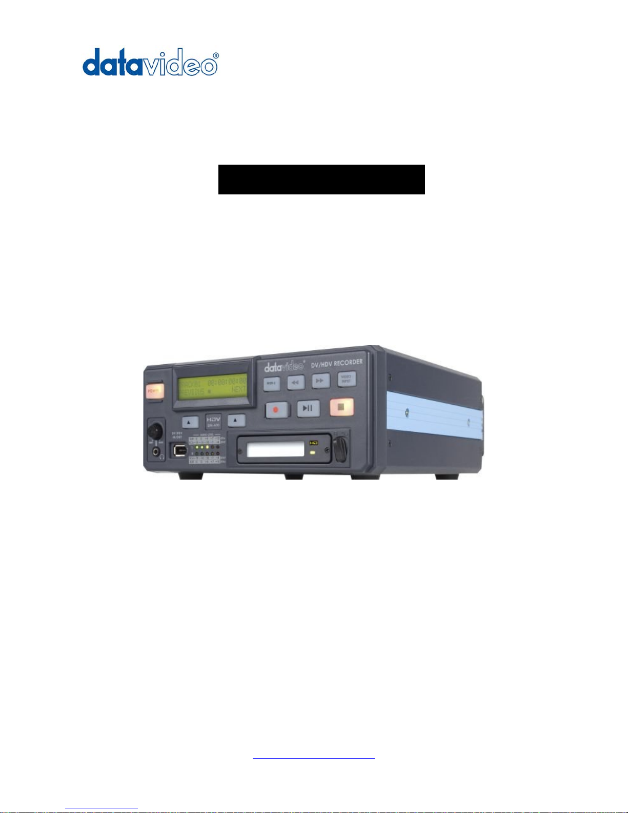
HD/SD Recorder
DN-600
Quick Start Guide
www.datavideo-tek.com
Page 2

- 2 -
Table of contents
Warnings and Precautions ............................................................................................................................. - 3 -
Warranty ........................................................................................................................................................ - 4 -
Disposal ......................................................................................................................................................... - 4 -
Packing List: .................................................................................................................................................. - 5 -
Outline and Features ..................................................................................................................................... - 6 -
How to mount 2.5" hard drive into removable caddy. .................................................................................... - 7 -
Connections & Controls ................................................................................................................................. - 8 -
Front Panel ............................................................................................................................................. - 8 -
Rear Panel ............................................................................................................................................ - 10 -
Providing Power ........................................................................................................................................... - 11 -
VTR Mode .................................................................................................................................................... - 11 -
Menu Navigation .......................................................................................................................................... - 12 -
General Setup ...................................................................................................................................... - 16 -
Recording ............................................................................................................................................. - 16 -
Recording ............................................................................................................................................. - 17 -
Playback ............................................................................................................................................... - 18 -
HDD Mode ............................................................................................................................................ - 19 -
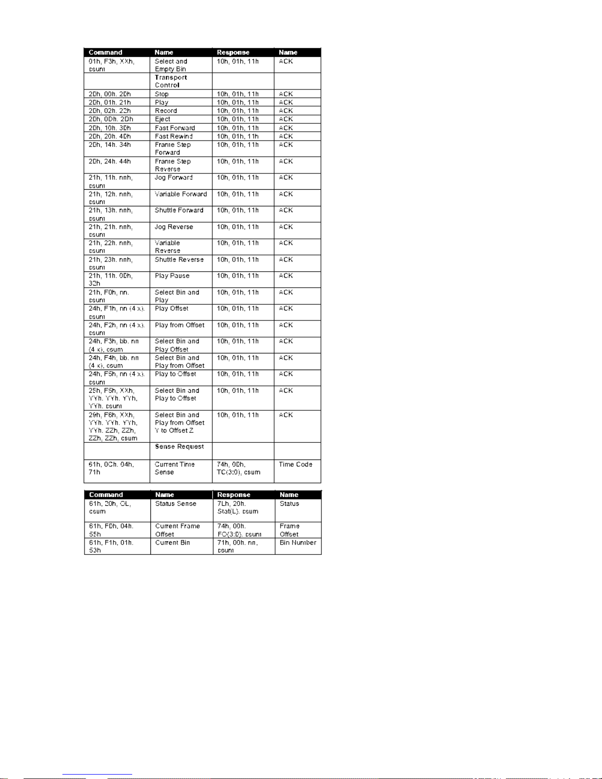
RS-232 Controller Command Set ................................................................................................................ - 20 -
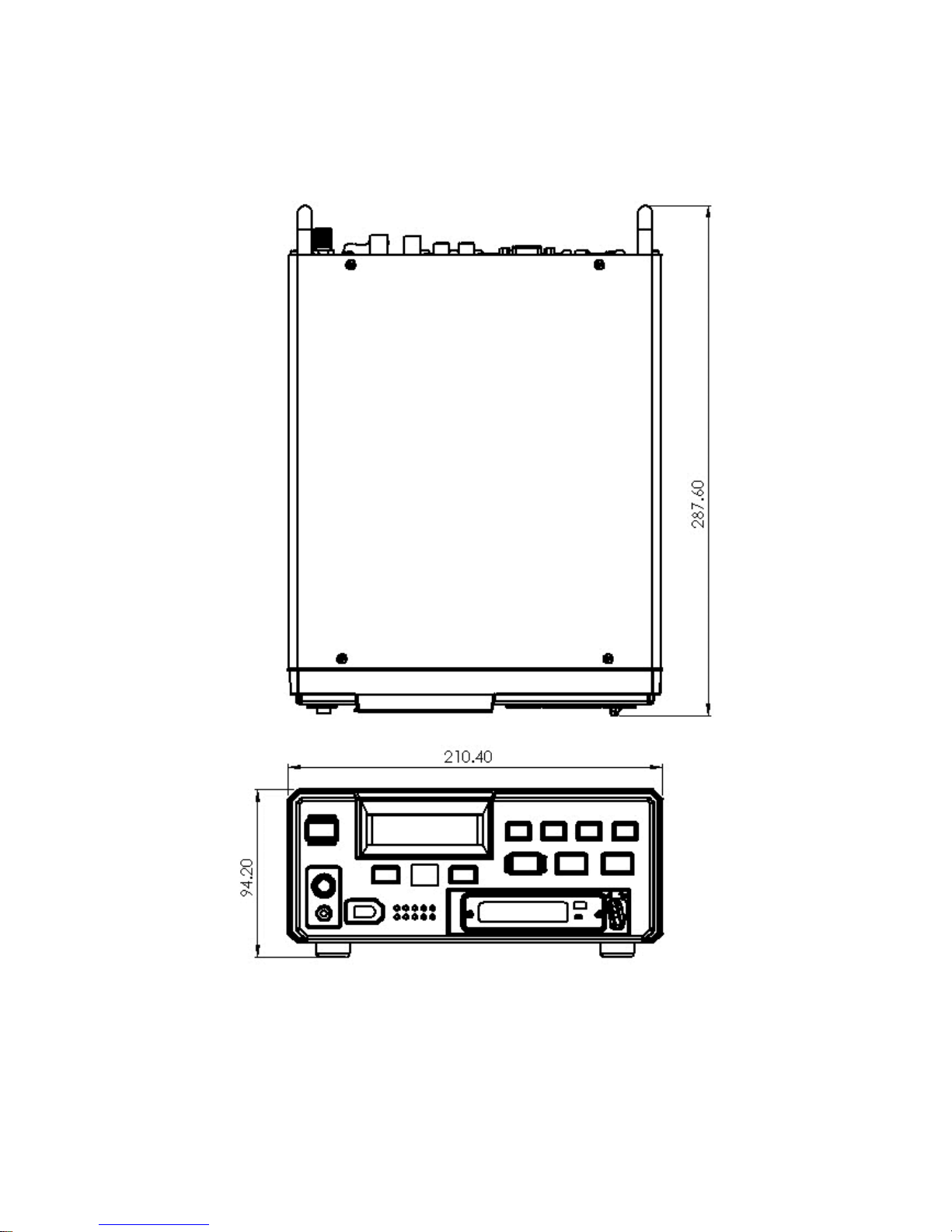
Dimension .................................................................................................................................................... - 22 -
Specifications ............................................................................................................................................... - 23 -
Service & Support ........................................................................................................................................ - 24 -
Page 3

- 3 -
Warnings and Precautions
1. Read all of these warnings and save them for later reference.
2. Follow all warnings and instructions marked on this unit.
3. Unplug this unit from the wall outlet before cleaning. Do not use liquid or aerosol cleaners. Use a
damp cloth for cleaning.
4. Do not use this unit in or near water.
5. Do not place this unit on an unstable cart, stand, or table. The unit may fall, causing serious damage.
6. Slots and openings on the cabinet top, back, and bottom are provided for ventilation. To ensure safe
and reliable operation of this unit, and to protect it from overheating, do not block or cover these
openings. Do not place this unit on a bed, sofa, rug, or similar surface, as the ventilation openings on
the bottom of the cabinet will be blocked. This unit should never be placed near or over a heat
register or radiator. This unit should not be placed in a built-i n ins tallation un les s pr oper vent i lat ion is
provided.
7. This product should only be operated from the type of power source indicated on the marking label
of the AC adapter. If you are not sure of the type of power available, consult your Datavideo dealer or
your local power company.
8. Do not allow anything to rest on the power cord. Do not locate this unit where the power cord will be
walked on, rolled over, or otherwise stressed.
9. If an extension cord must be used with this unit, make sure that the total of the ampere ratings on the
products plugged into the extension cord do not exceed the extension cord’s rating.
10. Make sure that the total amperes of all the units that are plugged into a single wall outlet do not
exceed 15 amperes.
11. Never push objects of any kind into this unit through the cabinet ventilation slots, as they may touch
dangerous voltage points or short out parts that could result in risk of fire or electric shock. Never
spill liquid of any kind onto or into this unit.
12. Except as specifically explained elsewhere in this manual, do not attempt to service this product
yourself. Opening or removing covers that are marked “Do Not Remove” may expose you to
dangerous voltage points or other risks, and will void your warranty. Refer all service issues to
qualified service personnel.
13. Unplug this product from the wall outlet and refer to qualified service personnel under the following
conditions:
a. When the power cord is damaged or frayed;
b. When liquid has spilled into the unit;
c. When the product has been exposed to rain or water;
d. When the product does not operate normally under normal operating conditions. Adjust only
those controls that are covered by the operating instructions in this manual; improper
adjustment of other controls may result in damage to the unit and may often require
extensive work by a qualified technician to restore the unit to normal operation;
e. When the product has been dropped or the cabinet has been damaged;
f. When the product exhibits a distinct change in performance, indicating a need for service
14. Due to the general consumer usage behavior, efficient power distribution on the field, corporate
environment responsibility by eliminating harmful substances such as carbon dioxide, sulphur
dioxide, etc, and other unexpected risks, this product does not provide standby power option
To avoid any possible static damage to your equipment please ensure your camcorder / deck is switched off
when connecting or disconnecting the IEEE-1394 cable.
Page 4

- 4 -
Warranty
Datavideo warrants that the equipment it manufactures shall be free from defects in material and
workmanship for a period of 12 months from the date of product purchased. If equipment fails due to such
defects, Datavideo will, at its option, repair or provide a replacement for the defective part or product.
Equipment that fails after the warranty period, has been operated or installed in a manner other than that
specified by Datavideo, or has been subjected to abuse or modification, will be repaired for time and material
charges at the Buyer’s expense.
This warranty does not affect your statutory rights within the Country of purchase.
Disposal
For EU Customers only - WEEE Marking.
This symbol on the product indicates that it will not be treated as household waste. It must be handed over to
the applicable take-back scheme for the recycling of electrical and electronic equipment. For more detailed
information about the recycling of this product, please contact your local Datavideo office.
Page 5

- 5 -
Packing List:
The following items should be included in the box. If any items are missing please contact your supplier.
1 x Power Supply (12V 1.5A)
2 x 2.5” Removable HDD Enclosur e
1 x USB mini to standard USB (Y type)
10 x M3 X 4 m/m Screws
2 x 2.0 X 6 m/m Screws
4 x Label
1 x Quick Start Guide
Page 6

- 6 -
Outline and Features
Portable recorder with removable media. The DN-600 features rugged, industry standard, 2.5-inch hard
disc drives in a metal case with patented shock protection mounts.
DN-600 is available in recording times ranging from 3 to 9 hours per drive.
DN-600 can be used in a docking bay for PC, stand-alone as portable media device, or with any of the
PC interface adapters offered.
Record and Playback as you would a tape recorder with familiar operational settings.
Connects to a computer as a standard Hard Disk Drive (HDD) with all recorded content appearing as
files inside folders for immediate download in a “drag and drop” fashion in faster than real time and ready
to edit. No more wasted capture time.
Record and playback using rugged internal Transactional File System technology and data presented in
HDD mode through emulation of standard file systems compatible with Windows and Mac.
Firmware update via simple file transfer in HDD mode.
Page 7

- 7 -
How to mount 2.5" hard drive into removable caddy.
N.B Hard Drive Support.
At the time of writing this manual the largest capacity HDD tested with the DN-600 is the
WD3200BEVT Western Digital 320GB.
For up to date information about HDD compatibility contact your local Datavideo Office
If your DN-600 does not come with a hard drive pre-fitted in the caddy please follow these
instructions to fit your own drive. Always check compatibility before buying hard drive.
1. Remove two screws from the 2.5" removable HDD rack rear cover then pull out the PCB
2. Assemble four screws to fasten 2.5" HDD on PCB
3. Push PCB into the HDD rack
4. Assemble two screws to fasten HD rack rear cover
5. Lock caddy into DN-600 by pushing lever to left.
Page 8

- 8 -
Connections & Controls
Front Panel
Power Light
Power light is for POWER ON/OFF status.
LCD Display
There are four lines in the LCD Displa y. The first line is used to displa y icons
that reflect some of the current settings of the unit. These settings include:
Battery Level
ANA / DIG(Video Source is Analog / Digital) /HDV(Unit is set for HDV mode)
Loop Play enabled
Time Remaining
The second line will display the recording file type set for the selected bin
(.MOV e.g.). W hile playing or recordi ng it a lso displa ys the c urrent cli p num ber
and the total number of clips in the bin.
The third line will display the bin number (01-
99) and a time number
(Hr:Min:Sec:Frame) . The ti m e number will r eprese nt t he abs olute tim e addr ess
or the time code of the f ram e being rec orded or played. When selecting a new
bin, the time num ber will b e th e length of the cont ent in th is b in. The f ourth lin e
annotates the significance of the soft keys.
Menu Navigation Left / Right soft key
The functions of the two Soft Ke ys found below the LCD are de pendent upon
the current operation mode. Each function changes with each different
operation mode. The Soft Key's current functi ons are displayed on the bottom
line of the LCD panel, directly above each respective left / right Soft Key.
Menu Navigation Menu key
Use this button to start navi gating as well as ex iti ng th e vario us opt ions offered
by DN-600. The functions are called out in the bottom two rows of the LC D.
Stepping through options is done by following the directions set in the LCD
annotations. At any time, an option can be exited by pressing this key.
Note: Main menu sele
ction can be accessed from a Stop or Idle mode.
Specialized menu selections are accessed while playing.
Fwd / Rew Buttons
In playback mode these buttons will operate as Fast Forward and Rewind
Buttons. If the Menu Butto n is pressed these buttons will navigate backwards
and forwards between the various menu options.
SD/HDV Source Switch
Where the recorder is set to operate with one of three signal types, either in
DV, NTSC or PAL, or in HDV, all frame rates. Note that changing between
type s will require ALL contents to be erased. Note that the current type chosen
will be marked with an asterisk.
Page 9
- 9 -
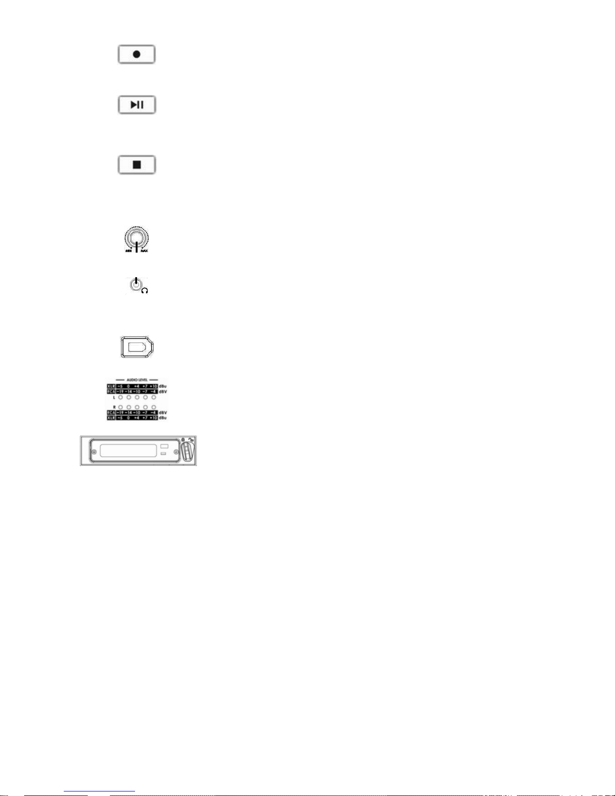
Record
In Idle Mode, pressing the 'PLAY' while the 'REC' button is held down will make
the unit ready to record.
Play / Pause
From the Stop or Idle mode, pressing th e 'PLAY' button plays back video from
the selected bin. While playin g, pressing the 'PLAY' button will toggle between
'PLAY' and 'PAUSE'.
Stop
In PLAY Mode, pressing the 'STOP' button will end play back and enter the
Stop m ode. In RECORD Mode, pressing the 'STOP' button will end recording
and enter the Stop mode.
Level Adjustments
The Audio Level Adjustments allow you to adjust the headphones volume.
headphones Jack
Accepts a stereo mini jack plug for stereo headphones. The headphone
volume is controlled by the Audio Level Adjustments.
DV In/Out Port.
This is a convenient fr ont m ount ed D V / I EE E-1394 Port for connec tio n to a DV
/ HDV camcorder, or to a PC for file transfer.
Audio Level
The Audio Input Level LEDs show the audio input levels from the incoming
source.
2.5" Removable HDD Rack
SATA & USB interface connecting to a PC for file transfer.
Page 10
- 10 -
Rear Panel
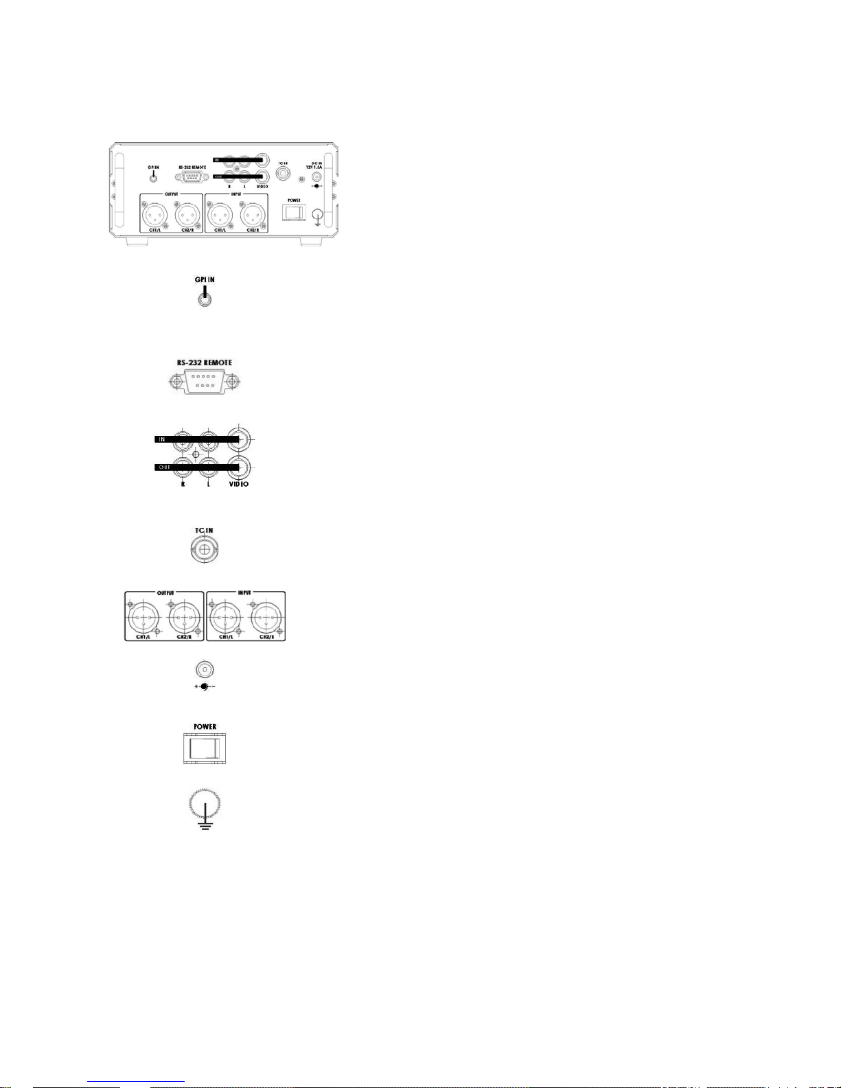
GPI IN
The GPI socket can be used for simple external control.
The DN-600 can accept p ulse or level trigger inputs, which ca n trigger
record or playback and pause commands
RS-232
Used to remotely control the DN-600.
Composite Video input & output
The connection is composite video input.
AUDIO IN
Accepts a RCA jack plug for audio input (Left &Right).
TC IN
The connection is for time code single input.
Audio input & output.
2 channels XLR Balanced Audio input & output.
DC In Socket
The connection is used for the battery or the AC adapter.
Power On / Off
Power On/Off Switch. Switches the power On / Off
Grounding Terminal
When connecting this unit to any other component, make sure that it is
properly grounded by connecting this terminal to an appropriate point.
When connecting, use the socket and be sure to use wire with a crosssectional area of at least 1.0 mm2.
Page 11

- 11 -
Providing Power
The DN-600 comes with an AC Adapter. Plug the output of either one into the DC Power connector located
on the Rear Panel. It is recommended that you have a DN-600 ins ert ed in the Ba y bef ore pow er up. Not
having one at this time, does not influence normal device operation. Move the power switch to the ON
position. The DN-600 will turn on and will wait for 5 seconds for you to press the Menu key to go into HDD
mode, after the wait period it will go into the VTR mode.
VTR Mode
Formatting the DN-600
The DN-600 will format a DN-600 to handle one of three signal types; HDV (all frame rates), or NTSC DV or
PAL DV. If an unformatted DN-600 is inserted, the DN-600 will recognize it and suggest it be formatted to its
signal type. If a DN-600 is inserted and is format for a signal type different than that of the DN-600, the
choice will be given to either re-format the DN-600 or set the DN-600 to the DN-600’s signal type.
Organize your shoot
A recorded length of video between its start point and following pause or stop point is called a clip. A clip can
be as short as one frame or as long as the whole storage capacity. Clips are stored in bins; a bin is
analogous to a tape. 99 bins are made available; Clips can be added to any bin at any time as long as there
is room available. The DN-600 always displays the clip number as well as the bin number.
Page 12
- 12 -
Menu Navigation
Main Level
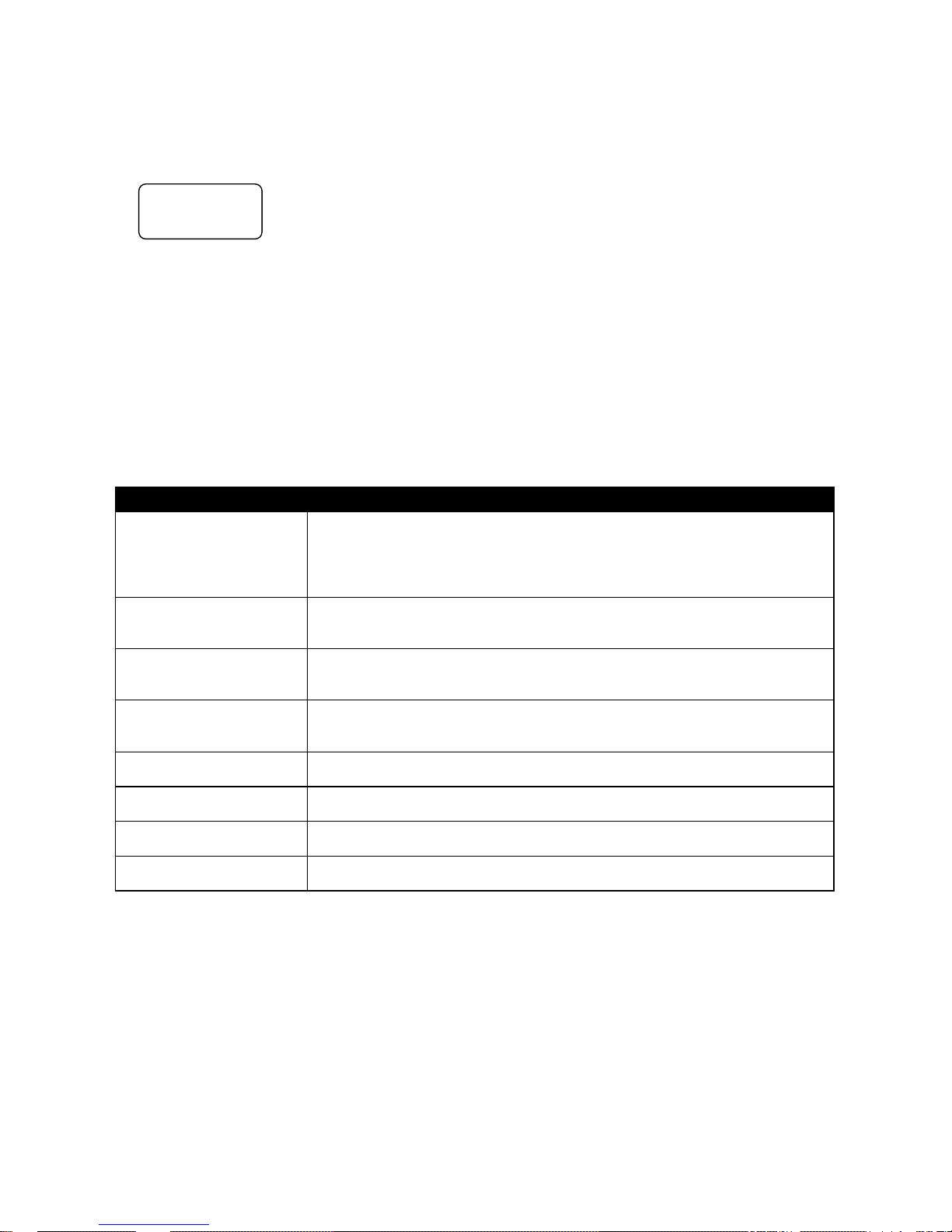
From the Idle or Start-up display, pressing the Menu key will enter the first level of options; these options are
the most commonly used ones. The lower three lines will look as below:
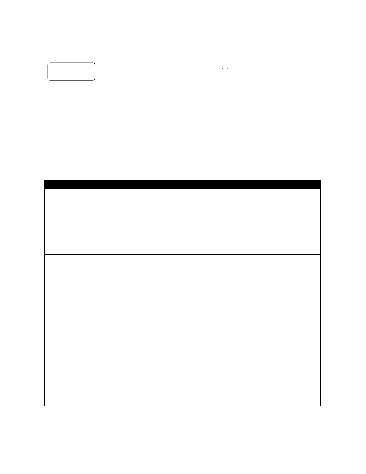
There are 8 options and they are:
MAKE MEDIA FILES
EMPTY THIS BIN ?
SELECT SOURCE
EMPTY ALL BINs ?
RECORD SETUP
PLAY SETUP
SYSTEM SETUP
FIRMWARE REVISION
Pressing the Next key will bring up the next option down on the list and will return to the top option from the
bottom. Table 1 details the actions for each option.
Menu Option Action taken
MAKE MEDIA FILES
Prepares the content to be seen by the computer in the HDD mode. The
operating system environment is previously set to either FA T32 or NTFS.
When there is recording content, This action needs to be taken before
connecting as an HDD.
EMPTY THIS BIN
Empties or erases the content within the presently selected bin, this step is
irrevocable once the final question has been asked.
SELECT SOURCE
When in DV mode, the signal to be recorded can be chosen to come either
from the Firewire input (DIG) as a digital signal or come from the breakout
cable as an NTSC or PAL compatible analog signal (ANA)
EMPTY ALL BINS
Empties or erases the content in ALL of the bins. This step is irrevocable once
the final question has been asked.
RECORD SETUP
Enters the Record Setup Menu group detailed in the named section
PLAY SETUP
Enters the Play Setup Menu group detailed in the named section
SYSTEM SETUP
Enters the System Setup Menu group detailed in the named section
FIRMWARE REVISION
Displays the current revision of the recorder’s firmware
Table 1 Menu Main Level
menu = exit
MAKE MEDIA FILES
ENTER NEXT
Page 13
- 13 -
Record Setup Level
Entered from the Main Level, this set of options enable various record related parameters and modes to be
setup. The lower three lines will look as below:
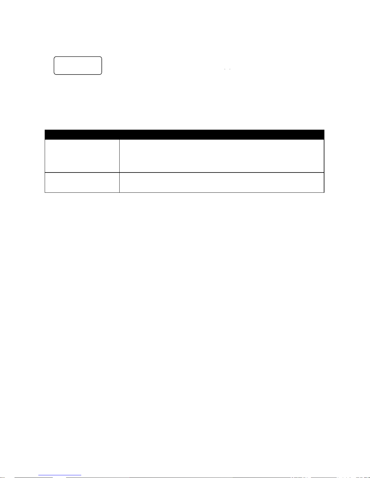
There are 8 options and they are:
SET RECORD FILE TYPE
SYNCtoTAPE CONTROL
SET RECORD DATE
RECORD PRE-TRIGGER
SET DEFAULT DV AUDIO
SET ASPECT RATIO
TIMELAPSE RECORD
PWR ON AUTO RECORD
Pressing the Next key will bring up the next option down on the list and will return to the top option from the
bottom. Table 2 details the actions for each option. Pressing the Menu key will return to the Main Level.
Menu Option
Action taken
SET RECORD FILE TYPE
Where the choice of file type is made for all unrecorded bins. File types cannot
be mixed within a bin. Choices are .mov, 2 types of .avi,
.mxf and for HDV, .m2t only. Note that the current type chosen will be marked
with an asterisk.
SYNCtoTAPE CONTROL
Where the recorder will look to the time code changing to indicate the need to
record. If the time code pauses then the recording is paused. With this setting
turned off, the record process will continue regardless of the time code
behavior. Note that the current selection will be marked with an asterisk.
SET RECORD DATE
This option modifies the date attribute of the created file when the source is
analog always, and when the source is digital if the date in the digital source is
invalid.
RECORD PRE-TRIGGER
When enabled, the last 8 seconds of video prior to the record trigger are
captured ahead of the video following the trigger. Note that the pre trigger is
not remembered across power cycles.
SET DEFAULT DV AUDIO
When the source is analog, this option sets the audio sampling frequency.
When the source is digital, this option helps the recorder make a correct guess
for the incoming audio sampling frequency. Note that the current selection will
be marked with an asterisk.
SET ASPECT RA TIO
When the source is ana log, this opt ion sets the 16:9 or 4:3 aspect rat io flag in
the stream to be recorded.
TIMELAPSE RECORD
Allows the DV recording of video at slower than real time through a choice of
one of 6 options. Note that the current selection will be marked with an
asterisk.
PWR ON AUTO RECORD
When enabled, the recorder will go directly into a record mode in the last bin
selected once power is applied.
Table 2 Record Setup Level
menu = exit
RECORD SETUP
Page 14
- 14 -
Play Setup Level
Entered from the Main Level, this set of options enable various play related parameters and modes to be
setup. The lower three lines will look as below:
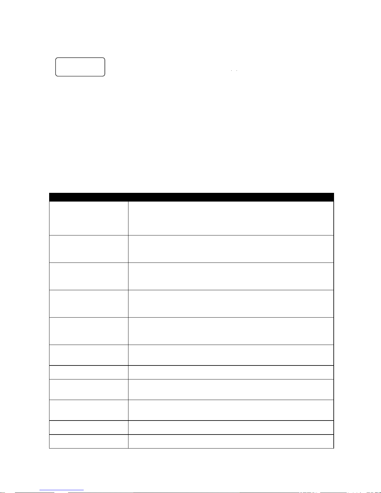
There are 2 options and they are:
SET LOOP PLAY
PWR ON AUTO PLAY
Pressing the Next key will bring up the next option down on the list and will return to the top option from the
bottom. Table 3 details the actions for each option. Pressing the Menu key will return to the Main Level.
Menu Option Action taken
SET LOOP PLAY
When enabled and the last frame has been played, the recorder will start
playing all over from the start. Note that the chosen mode is indicated by an
asterisk as well as the presence or absence of the loop play icon on the first
line.
PWR ON AUTO PLAY
When enabled, the recorder will go directly into a play mode in the last bin
selected once power is applied.
Table 3 Play Setup Level
menu = exit
PLAY SETUP
Page 15
- 15 -
System Setup Level
Entered from the Main Level, this set of options enables various system related parameters and modes to be
setup. The lower three lines will look as below:
There are 11 options and they are:
SET SIGNAL TYPE
SET FAT32/NTFS
MODIFY HDD VOLUME ID
SETUP HDD PARTITION
TC DISPLAY FORMAT
SET REMOTE CONTROL
TOTAL SPACE
UPGRADE FIRMWARE
SET GPI TRIGGER MODE
SET FACTORY DEFAULT
NTSC SETUP LEVEL
Pressing the Next key will bring up the next option down on the list and will return to the top option from the
bottom. Table 4 details the actions for each option. Pressing the Menu key will return to the Main Level.
Menu Option
Action taken
SET SIGNAL TYPE
Where the recorder is set to operate with one of three signal types, either in
DV, NTSC or PAL, or in HDV, all frame rates. Note that changing between
types will require ALL contents to be erased. Note that the current type
chosen will be marked with an asterisk.
SET FAT32/NTFS
This option chooses the computer’s file system to emulate, NTFS or FAT32.
Note that FAT32 has a 2GB file size limitation so clips longer than 2GB are
split into approximately 2GB files with no frames dropped. Note that the
current selection will be marked with an asterisk.
MODIFY HDD VOLUME ID
When connecting to a computer in the HDD mode, the disk will have for
volume name Datavideo xx. This option sets the xx value. A useful feature
when connecting multiple volumes at the same time as from a multi-shoot.
SETUP HDD PARTITION
A separate 6GB partition can be set up. The recorder will have no affect on
this partition so the user is free to name it, format it, store any type of data on
it with complete confidence that the recorder will not alter it.
SET TIMECODE DISPLAY
During recording and playback, this option chooses to display either the
Internal or the External time code. Note that the current selection will be
marked with an asterisk.
SET REMOTE CONTROL
This option either enables or disables the remote control capability. Note that
the current selection will be marked with an asterisk.
TOTAL SPACE
Displays the capacity of the DN-600 inserted in the recorder.
UPGRADE FIRMWARE
Allows the user to update the firmware of the recorder, provided a proper file
has been loaded on the DN-600.
SET GPI TRIGGER MODE
The GPI socket can be used for simple external control. The DN-600 can
accept pulse or level trigger inputs, which can trigger record or playback and
pause commands.
SET FACTORY DEFAULT
Recall FACTORY DEFAULT to be loaded into current setup
NTSC SETUP LEVEL
The setup level is set to 7.5 or 0.0 IRE.
Table 4 System Setup Level
menu = exit
SYSTEM SETUP
Page 16

- 16 -
General Setup
Before using your DN-600, there are a few basic operational conditions that must be set. These are found
under the System Setup Level of the menu tree (see table 4).
Set the signal type
Select HDV or DV If DV, select between NTSC or PAL. If the format chosen is NTSC, then a choice of setup
level is given. This level can be 0.0 or 7.5 IRE units and can be set under the NTSC SETUP LEVEL menu.
Note: Changing between signal types will erase the content in all bins.
Set up the HDD partitions to 1 or 2
The storage space can be broken into 2 partitions; the second partition reserves 6GB and is not seen by the
recorder. The second partition will appear as a second drive to the computer and the user is then free to use
this drive to store any data including spreadsheets, metadata and/or finished work. The DN-600 is
guaranteed not to overwrite data in this partition. Deleting all bins will not erase the data in the partition.
Note: Changing partition count will erase the content in all bins.
Choose operating system file system, FAT32 or NTFS
This option will set up the file system type seen by the computer in the HDD mode. NTFS does not have the
2GB file size limitation imposed by the FAT32 file system. With NTFS a recorded clip becomes one file no
matter its length. Although this choice can be done at any time before the making media file process it is
best to simply make it once.
Set the HDD volume ID
When connecting as an HDD the DN-600 volume name is Datavideo xx. If your application calls for multiple
DN-600s to be connected to the computer at the same time, it becomes helpful to have the volume name be
different for each DN-600. This option allows xx to be set between 00 and 99.
Select which time code to display
With DV, while recording or playing, the time code displayed can be either the externally generated time
code or the internally generated one. If the signal is analog and no time code is connected then the External
is generated the DN-600 and is in the dropped-frame format. The internal time code referred to here is the
absolute frame number of the recording in the selected bin and is in the non-dropped-frame format. The
absolute frame number starts at 00:00:00:00 in each bin. When the content is changed to files, the time
code presented to the NLE starts with the External value of the first frame of the content; if this value is
invalid then 00:00:00:00 is substituted. For HDV, the time code displayed is always the External time code.
Empty the current or all bins
The DN-600 is primarily a capture device, as opposed to an archiving device, and it is best to start out with a
fresh DN-600. Emptying (erasing) ALL bins will not only clear the DN-600 at once but it will also conveniently
reset the file system.
Updating the Firmware
To update the DN-600’s firmware, take a DN-600 that has undergone the MAKE MEDIA FILES process and
connect it to your computer. Copy the firmware update file to the root directory, level where all bin folders
appear, and rename it flash.bin. Next, insert the DN-600 in the DN-600 and select the UPDATE FIRMWARE
option and follow the instructions.
WARNING: Once the ERASE FLASH option has been selected, DO NOT turn power off until the firmware
has been updated. If the update is prematurely ended the recorder will be made inoperable.
Recording
Normal Record Checklist
A few parameters must be set properly for a standard recording and they are mostly grouped in the menu
level RECORD SETUP:
Select the DV video source
For DV recordings select the signal source in the Main menu level. It can be from the analog port (ANA) or
the 1394 port (DIG). Note that the output analog ports, Composite and S-video, are always live, regardless
of the signal source, ANA or DIG. When the source is analog, the signal is converted to DV digital and output
on the 1394 port at all times.
If Composite and S-video are connected to the analog input port simultaneously, the S-video signal is given
precedence. In HDV, the input and output are always the 1394 port and the analog section is made invalid.
Page 17

- 17 -
Set the file type:
A choice must be made for the eventual file type of choice should you want to connect the DN-600 in the
HDD mode to your computer and drag and drop your video content as files. The choices for DV are Microsoft
.avi type II, Canopus .avi type II, both commonly used in PCs, .mov, the QuickTime format used in Macs and
.mxf a new universal file format supported by a growing number of applications, Avid being the most well
known. In HDV mode, the file type is fixed at .m2t.
Note: The file format started with one bin will apply to all subsequent recordings in that bin and can only be
changed after the bin is erased or emptied.
Synchronize to tape motion
The recording of the DN-600 can be synchronized to the camera’s record button by turning Sync T o Tape ON
(ST1). Whenever the tape in the camera is rolling, so will the time code. DN-600 recognizes the motion and
will record along with the tape. When the motion stops, DN-600 will pause the recording. To record
continuously without regard for tape motion, switch Sync To Tape off (ST0). Some cameras control the DN600 directly through the 1394 interface and in these cases, use ST0 and let the camera do the work.
Select the sampling rate of the audio in the DV mode
This option will set the audio sampling rate to 32KHz or 48KHz when the video source is analog. When the
video source is digital this setting will be used as the starting guess frequency of the audio portion of the
digital stream. If the guess is incorrect then the first two frames of data will be discarded as the DN-600
resets itself.
Note: Only one type of audio sampling rate can be used within a bin.
Set the record date (optional)
The date attribute of the created file is set to this value when the source is analog. Each file representing a
clip gets it own date. If the source is digital then the record date from the digital stream is used. If that date
is not valid then the current record date set by this option is used.
Recording
Starting
Select one of 99 Bins by pressing the PREVIOUS or NEXT keys in the Idle menu.
Two common ways of starting to record are 1) by entering the record mode manually by holding the REC
button down while pressing the PLAY button. Or 2) the camera or device connected to the 1394 port sends a
record command. A third way is to issue a record command from the remote serial interface. See the
command protocol in Appendix B.
Pausing
The DN-600 will pause recording if time code is not moving and ST1 is set, otherwise it will record. When the
video source is digital the time code is embedded in the stream and it is always the time code recorded.
When the video source is analog, time code is the SMPTE longitudinal time code at the breakout cable. To
cause the recording to pause, that time code must be valid and not moving. If SMPTE time code is not
present then a time code is substituted starting at 00:00:00:00 for each bin and incrementing from there in a
dropped-frame manner (NTSC only). In this case, ST1 has no meaning. It is also possible to pause a
recording by pressing the PLAY key, in this mode, recording is resumed by pressing the PLAY key once
more and a new clip is created.
Warning: If power is interrupted while the recording is paused, all clip numbers added during the
current record session will be lost. No content however will be lost. Future firmware upgrades may
fix this behavior.
Note: If power is interrupted while recording, up to two seconds of the last video may be lost.
Recording
When recording the right soft key is called MARK. Pressing this key while recording will start a new clip with
no frames lost. Each time a recording is started a new clip is created. Up to 97 clips can be numbered in
each bin.
Note: Recording is done in a bin. A clip is automatically started at the beginning of the bin if the bin is empty
or appended to the last clip in the bin. A clip is never inserted between other clips in a bin.
Note: The minimum length of a clip is 2 seconds.
Page 18

- 18 -
Stopping
It is best to stop a recording by pressing the Stop key before turning power off.
Special Record Setups
Do elapsed time recording
In this option a recording can be set up to capture one of six time lapse settings. They are 1 frame per
second, per 2 seconds, per 5 seconds, every 4
th
frame, every other frame or 1 frame per trigger. The trigger
connection is found in the breakout cable.
Note: This mode is not saved when power is interrupted.
Note: A new clip is created only at the beginning of a time lapse recording.
Note: This option is not currently valid with HDV. Later firmware upgrades may turn this function on.
Use Record Pre-trigger
When this option is enabled the DN-600 is always in a record-ready mode when it is not playing. In this
mode it is continuously storing live data in its internal buffer which is 8 seconds in length. In this manner,
when a recording is started 8 seconds of history prior to the trigger already exists and is then captured to
disk.
Note: This mode is not saved when power is interrupted.
Power on auto record
When this option is enabled and DN-600 is powered on in the VTR mode the DN-600 will begin recording
immediately.
Playback
Playing setup
Set up loop play
When loop play is enabled and the last frame of the last clip is reached the DN-600 will start playing over
from the first frame of the first clip with no time lost.
Power on auto play
When this option is enabled the DN-600 will begin playing immediately when powered up in the VTR mode.
Playing
Play mode can be entered by one of three ways, the most common is to press the PLAY button; the other
two are by issuing a PLAY command through the IEEE-1394 interface or the serial port interface if it is
enabled. When playing, the time displayed is controlled by the TC DISPLAY FORMAT option. When play is
stopped, the time displayed is the time code of the last frame displayed.
When entering a play the soft keys will be FREV and FFWD for fast reverse and fast forward respectively.
Repeatedly pressing either soft key will cause the play to go repeatedly faster in the chosen direction up to
32x speed. A speed other than 1x is displayed in the bottom line. Also while playing pressing the Menu
button will give an alternate set of soft keys; SLOW and FAST. These keys, while keeping the same current
play direction, will extend the control of the speed down to the slow motion range of 1/32x. The menu button
will toggle between the two sets of keys. The Tally light will glow green while playing. If a play is entered after
a recording, the play wil start at the beginning of the first clip of the last recording. For example, a record
starts with clip 12, during the record the Make key is used to create clips 13 and 14. Play will start at clip 12.
This will remain until another bin is selected or power is turned off.
Pause and Go To Mark
While playing, pressing the PLAY key will paused the image. Pressing Play again will return to 1x play in the
forward direction. While in the play-pause mode, the soft keys will be l< and >l. These keys allow direct
access to the marks that are the starting and end frames of each clip. Counting the end frame of the last
clip, there will always be one more mark than there are clips. In this mode, the clip number display will be
substituted with a mark number display. Again, pressing the Menu key will present an alternate set of soft
keys, these will be <ll and ll> for frame stepping reverse and forward respectively. Holding either key down
for more than 2 seconds will cause a rapid stepping.
Page 19

- 19 -
HDD Mode
General
The HDD mode is the mode where the DN-600 appears to the computer as a Hard Disk Drive and not as a
VTR. The connection to the computer is done via the IEE-1394 connector. The HDD mode is entered by
pressing the Menu key within the 5 seconds after the DN-600 is powered on.
Note: Care must be taken when connecting the IEE-1394 cable in the DN-600 when the other end is already
connected to the computer. Do not attempt to insert the connector backwards as DC power from the
computer is present on the cable in the cable and can damage the sensitive receiver circuits in the DN-600.
Note: No software drivers are necessary for the computer to recognize the DN-600 as an HDD.
Preparation
Prior to turning on the DN-600 in the HDD mode and seeing your video as files instead of clips the MAKING
MEDIA FILES process must be undertaken.
MAKE MEDIA FILES
This operation prepares the recorded content to be seen by a computer by building the file wrappers around
the recorded content and emulating the computer’s operating file system. Two choices are available, FAT32
and NTFS and they are chosen by the SETUP FAT32/NTFS option.
Operating File System limitations
The FAT32 format is compatible with both Macs and PCs. This format limits the size of a file to a maximum of
2GB, in DV that translates to approximately 9+ minutes of video. A clip that lasts longer than 9min is broken
into multiple files each 2GB long with the last one making up the remaining time. If the split files are strung
on the time line of an NLE, no frame is lost over the transition. In addition, FAT32 has a clip boundary has a
resolution of 2 seconds so the beginning of a clip other than the first in a bin is most likely to contain the end
of the previous clip, up to 2 seconds' worth. Conversely the end of a clip is most likely to be found in the first
file of the next clip. For an accurate correlation of clip numbers between the VTR and the HDD mode, it is
best to keep each clip longer than 2 seconds and to have fewer than 97 per bin.
The NTFS format is fully compatible with PCs and is read compatible with Macs. Its main advantage is that it
does not impose a file size limitation to the DN-600 resulting in one file per clip. NTFS’ clip boundary is frame
accurate and therefore has perfect correlation with clip numbers in the VTR mode.
Note: Some NLEs cannot accept file sizes greater than 40GB, make sure your NLE is not one of them if you
plan on shooting one continuous take greater then 3 hours and using NTFS.
File Organization
After the media conversion is made, all bins that contained video will appear to the computer as folders
named BINxx where xx represents the BIN number ranging from 01 to 99. Inside each folder, each clip will
be represented as a file with an extension name .avi, .mov e.g. depending on the type chosen prior to
recording. Each file will be nam ed BxxCnnyy where xx again represents the bin number; nn represents the
Clip number ranging from 01 to 97. The number yy is the number of the spilt file caused by the FAT32
limitation
Connecting the DN-600 directly to the computer
Once the Make Media File is completed it is possible to eject the DN-600 and connect it directly to your
computer using the special Firewire cable or the optional USB-2 cable. Connect the 36-pin end of the cable
to the DN-600 and the other end to the 1394 or the USB port of the computer depending on the cable at
hand. The 1394 cable comes standard with the bundled DN-600 package. In this manner, the DN-600 is
connected to the computer while the DN-600 is free to capture more video.
Page 20
- 20 -
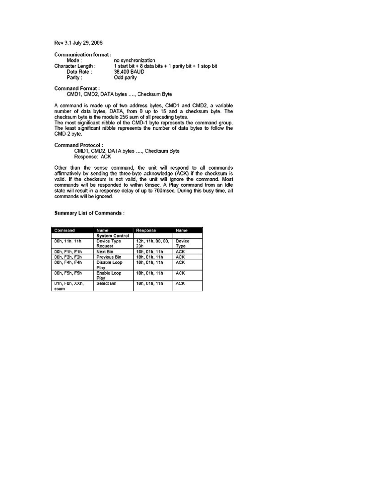
RS-232 Controller Command Set
Page 21
- 21 -
Page 22
- 22 -
Dimension
Page 23

- 23 -
Specifications
Analog Video Inputs
Composite video 1.0Vp-p, 75 Ohms internally terminated
Analog Video Outputs
Composite video 1.0Vp-p, must be terminated
Audio • Bandwidth 20~2 0KHz < +/- 3dB
• S/N Ratio > 50 dB
• THD. < 0.15%
Time Code In SMPTE, 0.5V to 5.0V p-p, BNC
Digital Video In/Out IEEE-1394, 400Mbps max, 6-pin
GPI Trigger 1.65V Threshold, 100K Ohms input, contact closure
Recording and Playback Formats
Analog Inputs and Outputs: DV25
Digital Input and Output: DV25, HDV, DVCPro-25
Recording time (minutes per 10GB)
DV25: 46.3
HDV: 49.4 at 1080i, 64.3 at 720p
Media File Format
DV25: *.avi (Type II, Microsoft, Canopus), *.mov, *.mxf (OP1A)
HDV: *.m2t
Operating File System Compatibility FAT32, NTFS
Input Voltage Requirement 12V typical
Power Consumption Idle: 4.3W, Play/Record: 6W, HDD mode: 5.3W
Dimension (W x H x D) 211mm (W) x 285mm (D) x 87mm (H)
Weight 3 kg
Temperature
Operating: +40°F to +104°F (+4°C to +40°C)
Non-Operating: -40°F to +149°F (-40°C to +65°C)
Vibration
Operating: 1.0G (5-500 Hz)
Non-Operating: 5.0G (10-500 Hz)
Shock
Operating: 250G (2ms)
Non-Operating: 5,000 (0.5ms)
Page 24
- 24 -
Service & Support
It is our goal to make your products ownership a satisfying experience. Our supporting staff is available to
assist you in setting up and operating your system. Please refer to our web site www.datavideo-tek.com for
answers to common questions, support requests or contact your local office below.
Datavideo Global Website: www.datavideo-tek.com
Datavideo Corporation
Tel: +1 562 696 2324
Fax: +1 562-698-6930
E-Mail: [email protected]
Datavideo Technologies Europe BV
Tel: +31-30-261-96-56
Fax: +31-30 261-96-57
E-Mail: [email protected]
Datavideo UK Limited
Tel: +44 1457 851 000
Fax: +44 1457 850 964
E-Mail: [email protected]
Datavideo Technologies Co., Ltd
Tel: +886 2 8227 2888
Fax: +886-2-8227-2777
E-mail: [email protected]
Datavideo Technologies China Co., Ltd
Tel: +86 21-5603 6599
Fax:+86 21-5603 6770
E-mail: [email protected]
Datavideo Technologies (S) PTE LTD
Tel: +65-6749 6866
Fax: +65-6749 3266
E-mail: [email protected]
Datavideo HK Limited.
Tel: +852 2833 1981
Fax: +852-2833-9916
E-mail: [email protected]
Datavideo France
Tel: +33 1 60 37 02 46
Fax: +33 1 60 37 67 32
E-Mail: [email protected]
Datavideo India
Tel: +91 120 4309120
Fax: +91 120 4309121
E-Mail: [email protected]
All the trademarks are the properties of their respective owners.
Datavideo Technologies Co., Ltd. All rights reserved 2018
G082060618B2
 Loading...