

Page 1
Page 2

Table of Contents
GENERAL INFORMATION.........................................................................................................4
COPYRIGHT................................................................................................................................................................................4
NOTICES AND CLASSIFICATIONS.....................................................................................................................................4
FCC-B Radio Frequency Interference Statement ....................................................................................................4
CONTACT US.............................................................................................................................................................................4
Data Watch Technologies Co., Ltd.................................................................................................................................4
PRECAUTIONS FOR THE RAID UNIT .........................................................................................5
GENERAL PRECAUTIONS.....................................................................................................................................................5
RAID UNIT PRECAUTIONS..................................................................................................................................................5
INTRODUCTION.......................................................................................................................6
FEATURES..................................................................................................................................................................................6
SYSTEM REQUIREMENT......................................................................................................................................................7
PC................................................................ . . . . . . . . . . . . . . . . . . . . . . . . . . . . . . . . . . . . . . . . . . . . . . . . . . . . . . . . . . . . . . . . . . . . . . . . . . . . . . . . . . . . . . . . . . . . . . . . . . . . . . . . . . . . . . . . . . . . . . ................7
MAC...................................................................... . . . . . . . . . . . . . . . . . . . . . . . . . . . . . . . . . . . . . . . . . . . . . . . . . . . . . . . . . . . . . . . . . . . . . . . . . . . . . . . . . . . . . . . . . . . . . . . . . . . . . . . . . . . . . . ..............7
SYSTEM UNIT VIEWS................................................................................................................8
FRONT VIEW.............................................................................................................................................................................8
INSIDE VIEW.............................................................................................................................................................................8
BOTTOM VIEW.........................................................................................................................................................................9
PACKAGE CONTENTS............................................................................................................................................................9
INSERTING HARD DRIVES IN THE RAID UNIT...........................................................................10
FASTEN THE HDD PLACEMENT HOLDER ONTO THE HDDS..............................................................................11
RAID MASTER........................................................................................................................16
INSTALLATION .....................................................................................................................................................................16
RAID MASTER MENU.............................................................................................................17
RAID MASTER: OPERATION....................................................................................................18
CREATE A RAID.....................................................................................................................................................................18
CHANGING THE MOST RECENT ASSIGNED RAID MODE.....................................................................................20
DELETING AN ASSIGNED RAID MODE........................................................................................................................22
REBUILD...................................................................................................................................................................................24
MIXED RAID STATUS..........................................................................................................................................................28
DEVICE INFORMATION......................................................................................................................................................30
NUMBER OF DISKS SUPPORTING EACH RAID MODE...............................................................31
LED INDICATORS....................................................................................................................31
POWER LED............................................................................................................................................................................31
DISK LEDS................................................................................................................................................................................31
DISK VOLUME OVER 2TB........................................................................................................32
SAFE REMOVAL OF THE RAID UNIT........................................................................................32
RAID MODES..........................................................................................................................33
RAID O (STRIPING)..............................................................................................................................................................33
Page 3

RAID 1 (MIRRORING).........................................................................................................................................................34
SPAN (LARGE).......................................................................................................................................................................34
JBOD (NON RAID).................................................................................................................................................................35
Q&As ....................................................................................................................................36
GENERAL.................................................................................................................................................................................36
DAISY CHAIN..........................................................................................................................................................................36
OLD HDDs................................................................................................................................................................................36
HDD SIZE..................................................................................................................................................................................36
HDD CAPACITY......................................................................................................................................................................37
DISCREPANCY IN REPORTED & ACTUAL SIZE CAPACITY...................................................................................37
REBUILD...................................................................................................................................................................................37
RAID MASTER: CONNECTION RESTRICTION...........................................................................................................37
OVER 2TB ..............................................................................................................................................................................38
LINUX........................................................................................................................................................................................39
APPENDIX..............................................................................................................................40
Page 4
GENERAL INFORMATION
COPYRIGHT
Copyright @ 2010 Data Watch Technologies Co., Ltd. All rights reserved. No part of
this publication may be reproduced, stored in a retrieval system, or transmitted in any
form or by any means, electronic, mechanical, photocopying, recording or otherwise,
without the prior written consent of Data Watch Technologies Co., Ltd.
The product information provided in this manual is subject to change without prior
notice and does not represent a commitment on behalf of the vendor. The vendor
assumes no liability or responsibility for any errors that may appear in this manual.
NOTICES AND CLASSIFICATIONS
FCC-B Radio Frequency Interference Statement
This device complies with Part 15 of the FCC rules. Operation is subject to the following
two conditions:
This device may not cause harmful interference.
This device must accept any interference received, including interference that may
cause undesired operation.
This equipment has been tested and found to comply with the limits for a Class B
digital device, pursuant to Part 15 of the FCC rules. These limits are designed to
provide reasonable protection against harmful interference when the equipment is
operated in a commercial environment. This equipment generates uses and can radiate
radio frequency energy and, if not installed and used in accordance with the instruction
manual, may cause harmful interference to radio communications.
CONTACT US
We are committed to offer economical, high-quality connectivity and storage enclosure
solutions to the market. Your questions, inquiries or comments are welcomed. For the
latest version of User Manual & Technical Support, please go to our website at
www.datawatchtech.com.
Data Watch Technologies Co., Ltd.
3F, No. 60, Lane 321, Yang Guang St.,
Nei Hu, Taipei 114 Taiwan
Tel: +886-2-8797-8868
Fax: +886-2-8797-4801
Email: [email protected]
4
Page 5

PRECAUTIONS FOR THE RAID UNIT
GENERAL PRECAUTIONS
The main circuit board of the RAID Unit is susceptible to static electricity.
Proper grounding is required to prevent electrical damage to the RAID
Unit or other connected devices, including the host computer. Always
place the RAID Unit on a smooth surface and avoid all dramatic
movement, vibration and percussion.
Do NOT allow water to enter the RAID Unit.
Do NOT place the RAID Unit close to magnetic devices (such as a mobile
phone), high-voltage devices (such as a hair dryer), or near a heat source
(such as on the dashboard of a car or any place where it will be exposed
to direct sunlight).
Use only the power supply cable provided with the RAID Unit.
Can use both 9.5mm or 12.5mm high 2.5” SATA HDDs inside the RAID
Unit.
Do NOT attempt to service this RAID Unit yourself. Please contact
Technical Support regarding any parts other than ones mentioned in the
“Installation” section of this User’s Manual.
Do NOT block the ventilation. Proper airflow is required to ensure reliable
operation and to prevent overheating.
Do unplug the RAID Unit from the electrical outlet when not in use to
provide an ecological friendly environment.
RAID UNIT PRECAUTIONS
Installation of RAID MASTER software in the host computer is required for
proper operation.
Any loss, corruption, or destruction of data is the sole responsibility
of the user of the RAID Unit. Under no circumstances will the
manufacturer be held liable for the recovery or restoration of any
data.
5
Page 6

INTRODUCTION
Thank you for purchasing the DataTale AIR (RS-S2TJ, 2.5-inch 2-HDD RAID System).
The DataTale AIR with RAID MASTER (Graphic User Interface) provides considerable
storage capacity with general high-tech RAID configuration options in a desktop storage
device. The RAID MASTER allows easy configuration of RAID Modes: JBOD (Non
RAID), RAID 0 (Striping), RAID 1 (Mirroring), and Span (Large).
Please read thoroughly and follow the instructions provided in this manual. Failure
to do so may result in damage to the RAID Unit, and any or all of the connected
devices.
FEATURES
• Supports current 2.5-inch (9.5mm or 12.5mm thick) SATA II compliant HDDs, fully
backward compatible with SATA 1.0 and SATA 1.0a compliant HDDs
• Supports over 2TB storage capacity
• Connects flexibly via Hi-Speed USB (USB2.0 connection), IEEE 1394b (FireWire
800 connection), or eSata (eSATA connection)
• Combines RAID Unit and 1394 repeater functionality
• Provides JBOD (Non RAID), RAID 0 (Striping), RAID 1 (Mirroring), and SPAN
(Large) for effective storage management
• Supports Rebuild under Raid 1 mode
• Configures RAID modes easily using RAID MASTER, no IT expertise required
• Monitors RAID Unit status via LED indicators or RAID MASTER
• Powers RAID Unit via FireWire 800 bus power, or AC/DC Power Adapter
• Includes a black pouch, easy for travel with plenty of protection
6
Page 7

SYSTEM REQUIREMENT
PC
• 266MHz or faster CPU (Windows Vista requires a minimum 800MHz CPU)
• 64MB of RAM (Windows Vista requires 512MB of RAM)
• Microsoft Windows 2000, XP, 2003, Vista, 2008, 7, or higher
• One available USB 2.0, eSATA, or IEEE 1394b port
MAC
• Macintosh PowerPC or Intel processors
• 64MB of RAM (Mac OS X 10.4 requires 256MB of RAM)
• Mac OS X 10.4 (Intel) or higher
• One available USB 2.0, eSATA, or IEEE 1394b port
• Time Machine Compatible
2.5-inch SATA compatible hard drive is required for the RAID Unit. Once the
HDD(s) is/are formatted, the actual available storage capacity can vary depending on
the selected operating environment (normally 5-10 % less).
7
Page 8
SYSTEM UNIT VIEWS
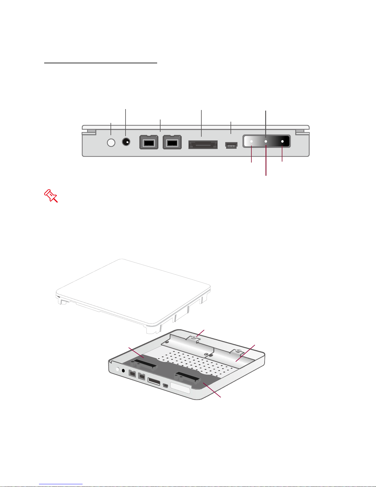
FireWire 800
DC IN
Power Switch
eSATA
USB
LED Panel
Power
Disk1
Disk2
HDD Placement Holders
HDD Screws
Disk1
Disk2
FRONT VIEW
The status indication of each LED indicator is listed under the LED INDICATORS
section.
INSIDE VIEW
8
Page 9
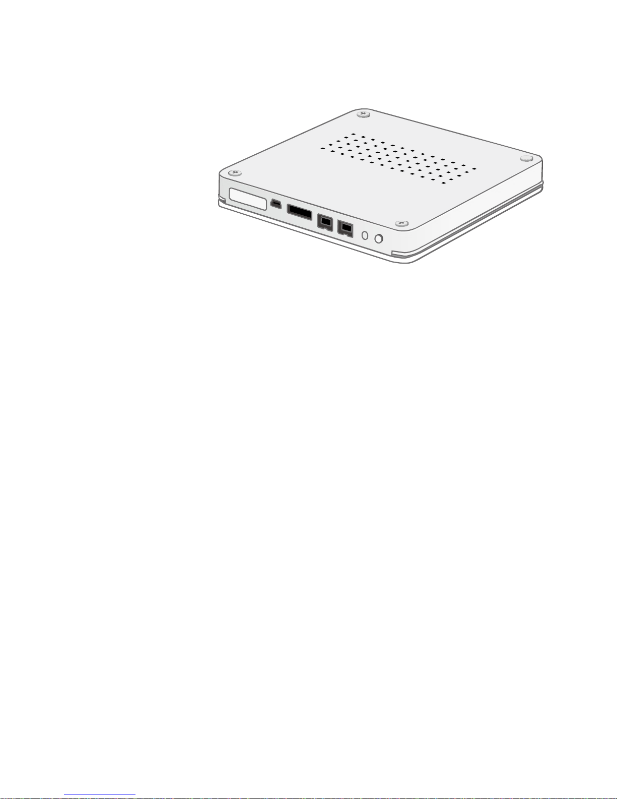
BOTTOM VIEW
PACKAGE CONTENTS
RS-S2TJ 2.5-inch RAID Unit
Power Adapter
FireWire cable
eSATA cable
USB cable
4 HDD Mounting Screws
Carrying Case
User Guide
9
Page 10
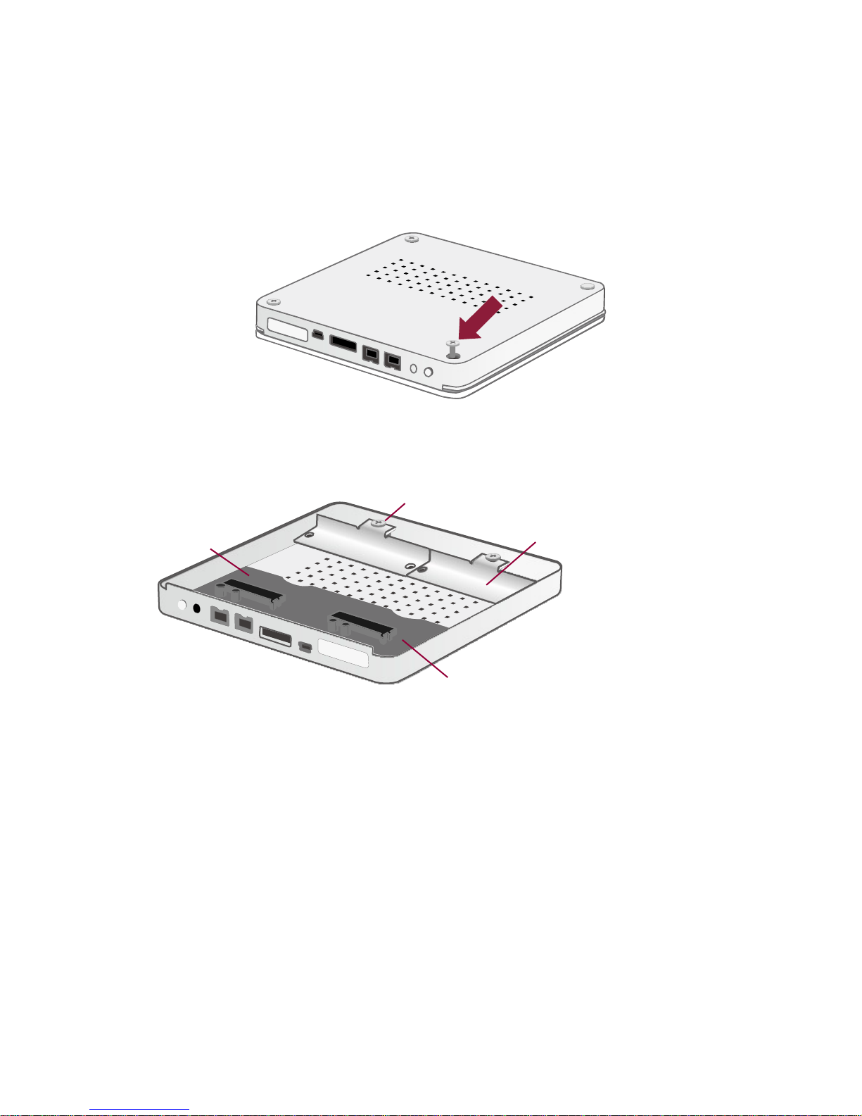
INSERTING HARD DRIVES IN THE RAID UNIT
HDD Placement Holders
HDD Screws
Disk1
Disk2
To assemble the RAID Unit, please follow the steps listed in the instructions below:
1. Place the RAID Unit with its Bottom View facing you. Unfasten all four (4) Casing
Screws with a Phillips screwdriver. Afterwards, turn the RAID Unit to its Cover side.
2. Lift the Cover upward to remove it. When opened, the PCBA boards (Printed Circuit
Board) should be securely in place inside the RAID Unit.
10
Page 11
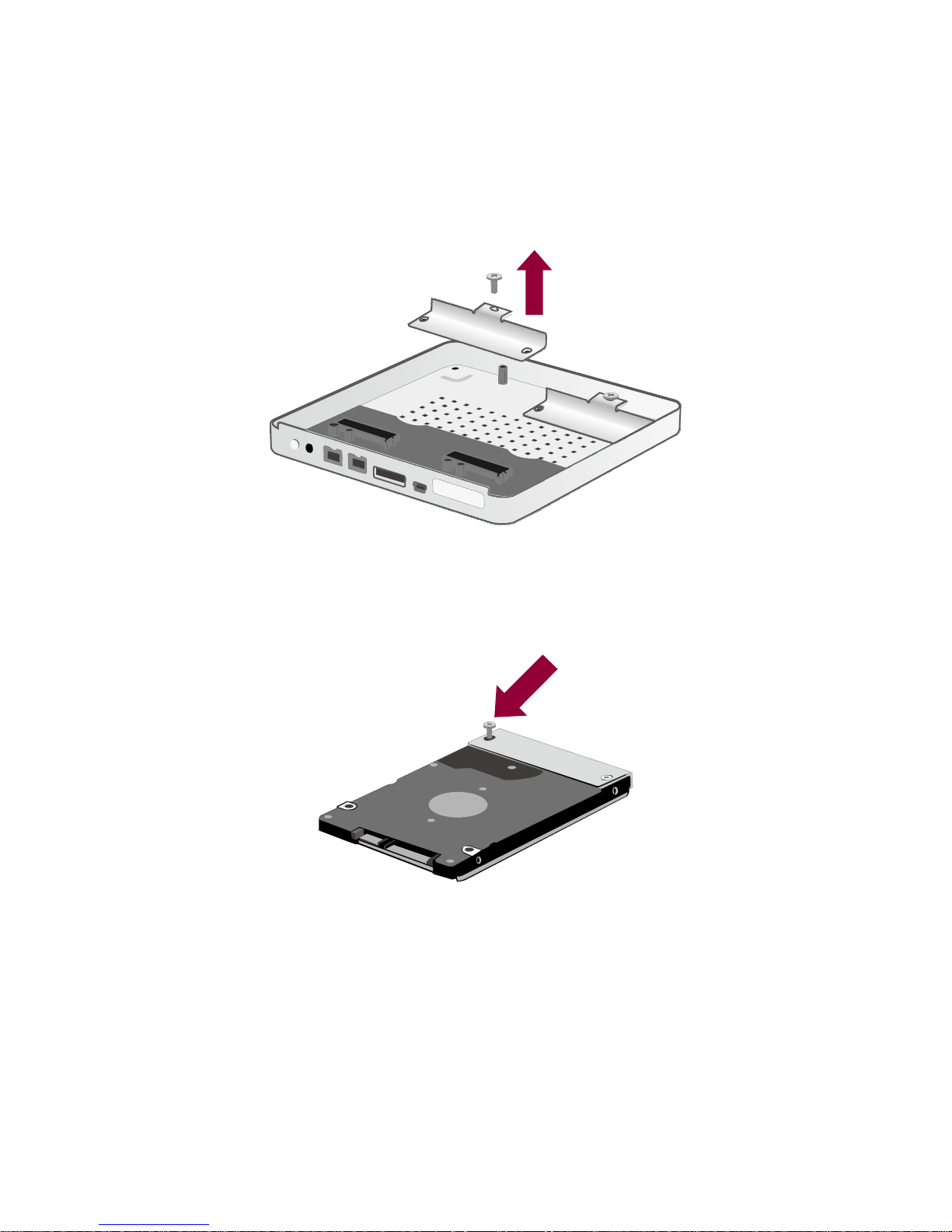
FASTEN THE HDD PLACEMENT HOLDER ONTO THE HDDS
3. Unfasten the HDD Screw from the HDD Placement Holder(s) to remove from the
Bottom casing.
4. Position the HDD Placement Holder onto the HDD end, facing away from the
interface connectors and aligned with the screw hole openings. Fasten the HDD
Placement Holder onto the HDD by inserting and tightening two (2) HDD Screws on
both ends of the HDD Placement Holder.
Repeat Steps 3 and 4 for the other HDD.
11
Page 12
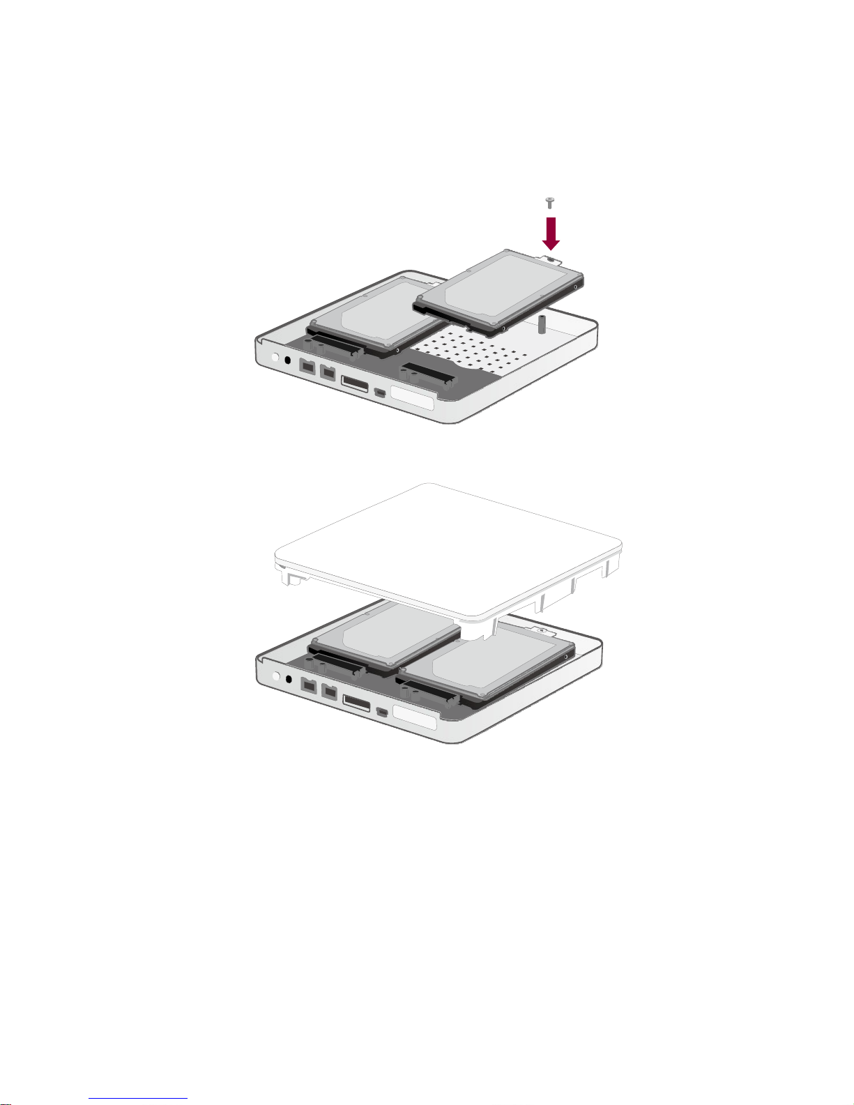
5. Carefully insert the SATA connector of the HDD into the slot on the PCBA board until
it’s firmly connected, ensuring that the hard drive and HDD Placement Holder’s
alignment are properly situated. Then, re-fasten and tighten the HDD Screw
previously removed from the HDD Placement Holder and the casing.
Repeat the same procedure for the other HDD.
6. Place the RAID Unit facing you. Align the Cover according to the appropriate
interface opening gaps and place it on the RAID Unit.
12
Page 13
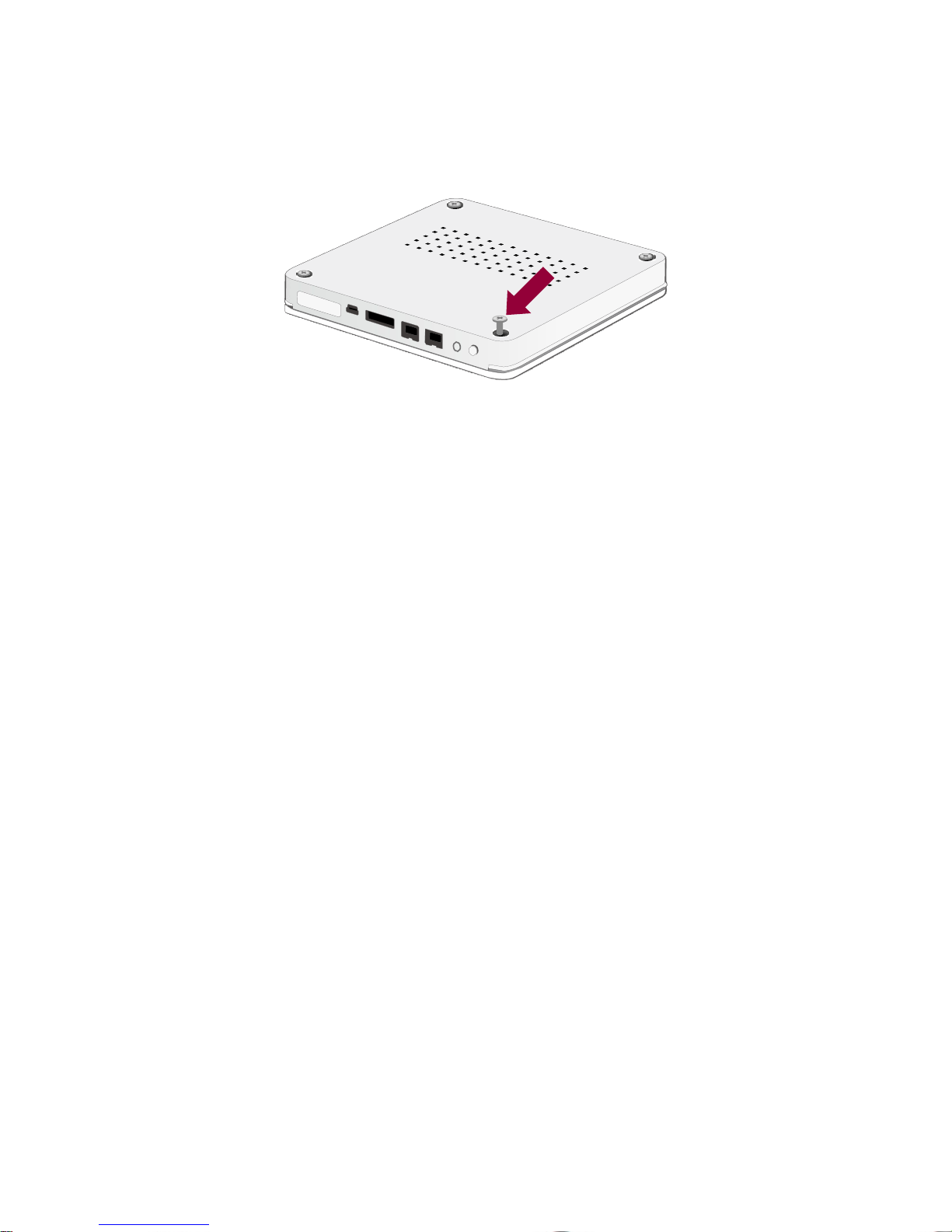
7. Once the Cover is placed on the RAID Unit, use both hands to firmly hold and turn
the RAID Unit to its Bottom View. Find the four (4) Casing Screws previously taken
out before and re-fasten them in the appropriate screw holes.
13
Page 14
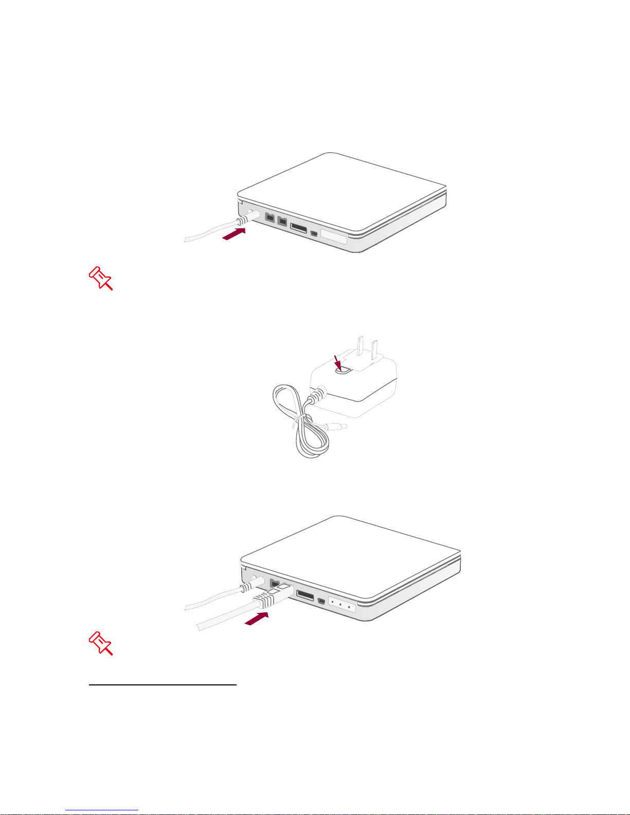
CONNECTING THE RAID UNIT TO A COMPUTER
Press here to release the clip
To connect the RAID Unit, please complete the following steps:
1. Connect the AC/DC Power Adapter to the RAID Unit.
If need to change the Adapter Head, press the click release to slide off the
existing Adapter Head from the AC/DC Adapter. Then, replace it with a different
Adapter Head in the same manner.
2. Insert both ends of the USB 2.0, eSATA, or FireWire 800 cable(s) into the
corresponding port of the RAID Unit and the host.
Connection of the RAID Unit to a computer via two or more interfaces simultaneously
is highly not recommended, especially for data transfers.
14
The RAID Unit should only be connected to a host computer via one interface.
Page 15
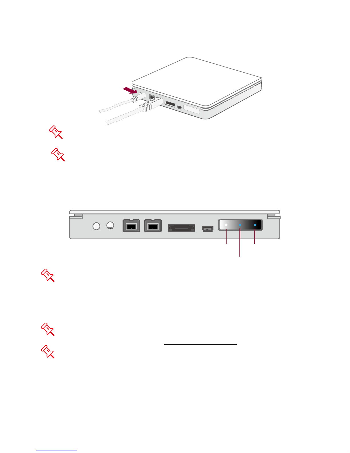
3. Press the Power Switch to “turn on” the RAID Unit.
Power
Disk1
Disk2
The RAID Unit can also be powered by using only the FireWire 800 cable,
without the AC/DC Adapter.
Press the Power Switch for at least 3 seconds when shutting down the RAID
Unit.
4. When connected, the Power LED light will become steadily white, and the Disk LED
lights will become blue and flash until the HDDs are detected.
There’s no need for any concerns if the Disk LEDs blink or flash in red for a very
short period of time during power on. When the HDDs are detected, the Disk LEDs will
become and remain in blue.
5. You are now ready to begin using your RAID Unit!
Due to compatibility issues, if you use the eSATA interface to do the data transfer,
the Silicon Image eSATA host controller is highly recommended.
When using FireWire 800, you can “Daisy Chain” and connect other computer
hardware or digital devices to your RAID Unit (such as digital video camera, another
HDD, DVD writer, and much more). Please see “Daisy Chain” under “Q&As” Section
for more information.
15
Page 16

RAID MASTER
The RAID MASTER is a newly-designed GUI Software specifically for our DataTale
AIR. The RAID MASTER gives a more convenient yet modern way to manage your
RAID Unit.
INSTALLATION
To install the RAID Master, please download software at the following link:
Windows Users: http://oyendigital.com/tech/RAID_MASTER_WIN.zip
1. Upon completion of the download, double-click on the file to unzip it.
2. Drag the folder to the desktop or any preferred location.
3. Open the folder and double-click on RAID MASTER and the menu should
appear. You are now ready to configure your RAID.
Mac Users: http://oyendigital.com/tech/RAID_MASTER_MAC.zip
1. Upon completion of the download, open the file to begin the installation.
2. The RAID Master GUI will be available in the Applications folder.
3. Click on the file RAID_Master_Mac to start the GUI. You are now ready to
configure your RAID.
The RAID MASTER can only configure the RAID when connected via USB 2.0 or
FireWire 800. If you choose to use eSATA for data transferring, please set up the RAID
configuration via USB or FireWire first.
16
Page 17
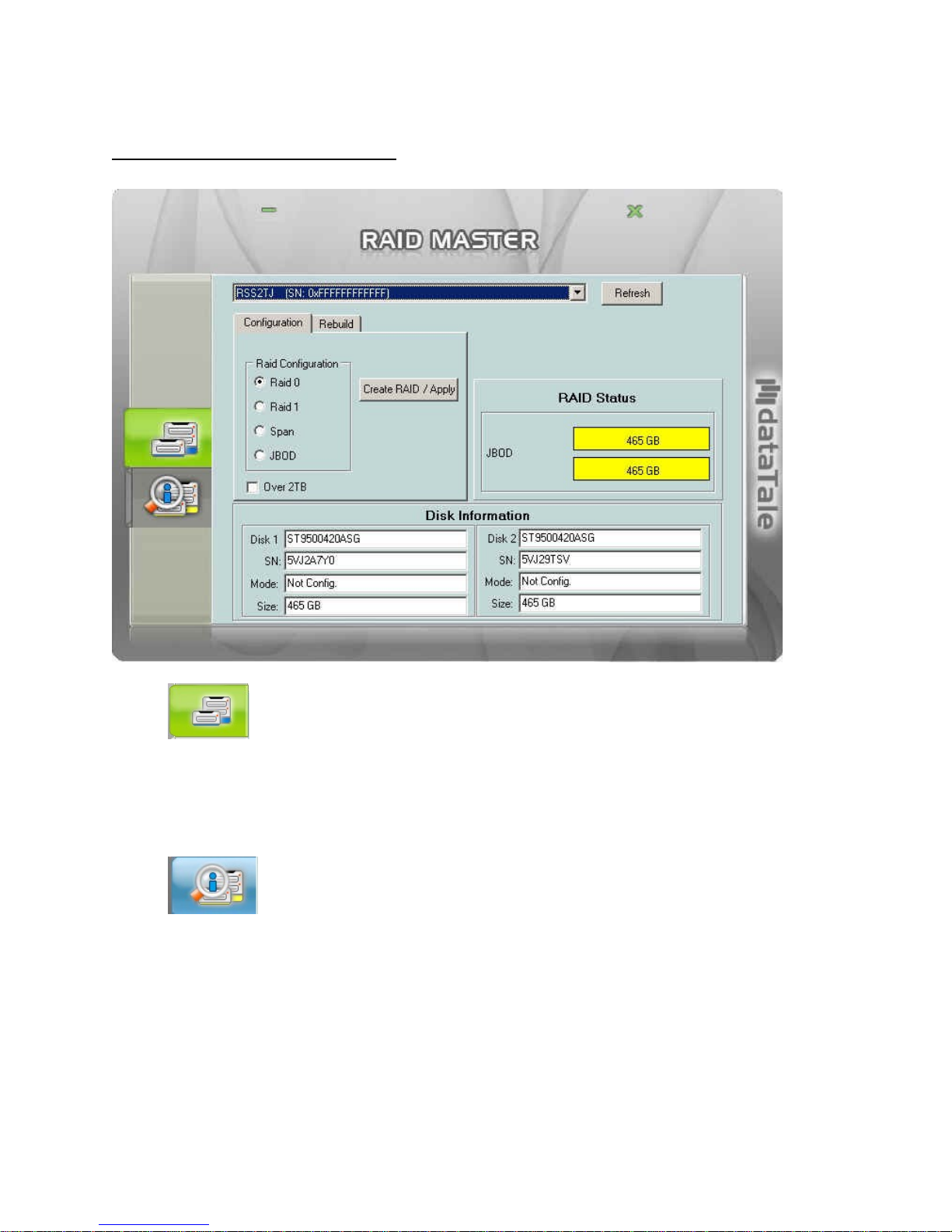
RAID MASTER MENU
• CONFIGURATION & REBUILD:
o Shows a single connected RAID unit, or multiple connected RAID Units.
o Supports RAID configurations under Configuration and Rebuild options
o Provides HDD(s)’ current RAID status
o Indicates individual HDD(s)’ current disk information
• DEVICE INFORMATION:
o Provides the basic information of the RAID Unit itself, once the RAID Unit
is connected to the host: the Device’s information, and serial number for
each inserted HDDs.
17
Page 18
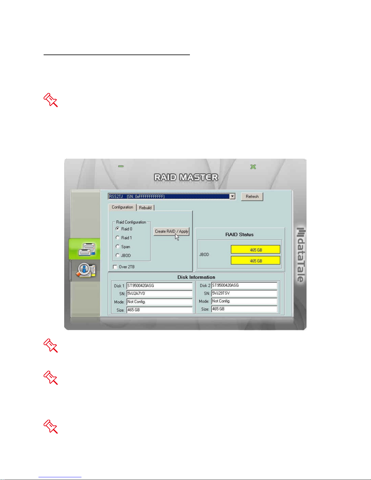
RAID MASTER: OPERATION
CREATE A RAID
To setup RAID functions for the RAID Unit, please complete the following steps:
Creating a new RAID mode will delete all data stored on the HDD(s). If you have
important saved data in the hard drives, backup all data before formatting the RAID
Mode.
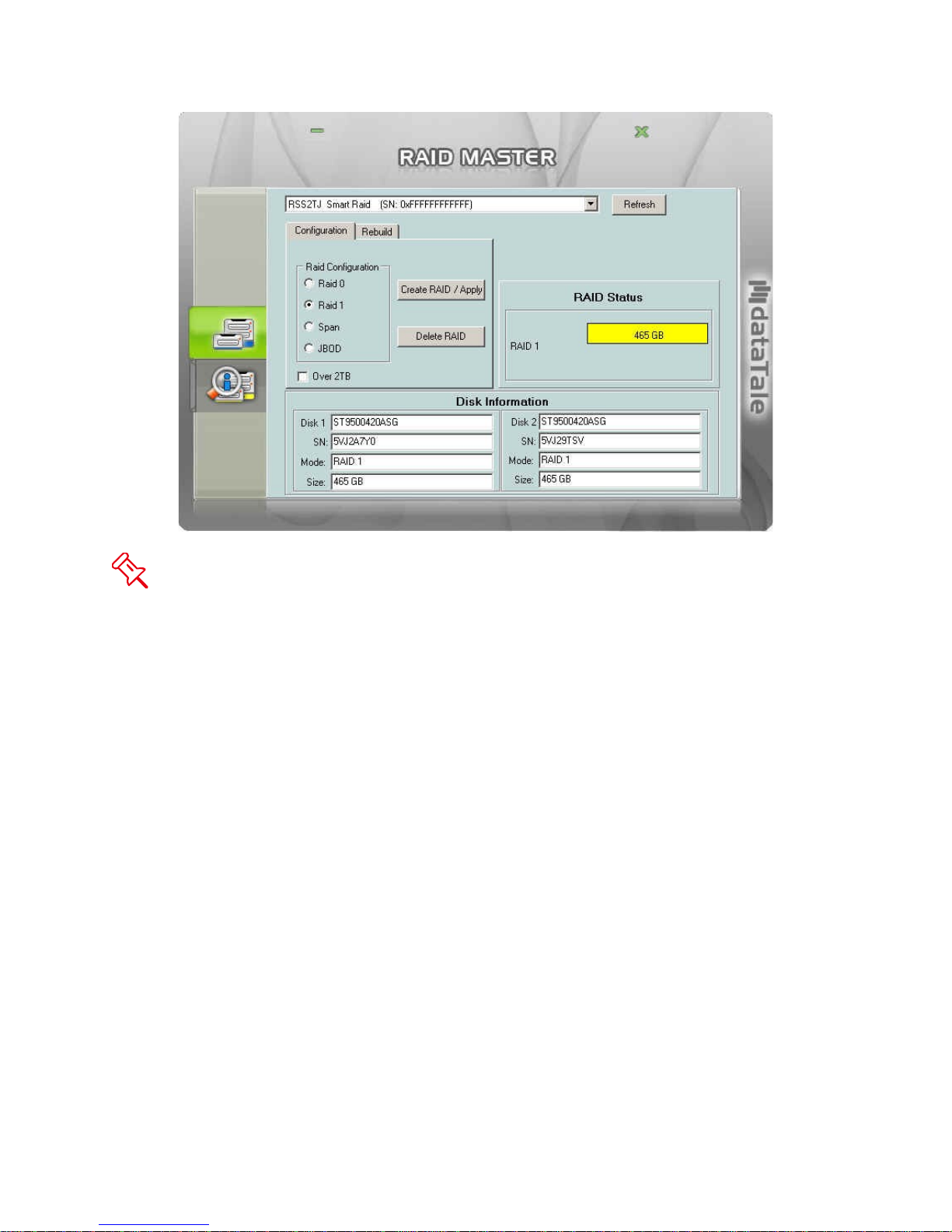
1. Under the “Configuration” option tab, select the RAID mode preferred and click
the “Create RAID/Apply” icon.
If cannot see what is/are connected as part of the RAID Unit, press the “Refresh”
button on top of the first sub-menu (top). The information should appear afterwards.
Please review the RAID mode options under “RAID MODES” to choose the best
suitable RAID mode for your needs and desire. If the number of inserted HDDs does
not qualify the quantity needed for a particular RAID mode, the RAID MASTER’S
“Create RAID/Apply” icon will not be available to click (faint image).
If the OS of the host can support more than 2TB HDD(s) storage capacities and
18
Page 19
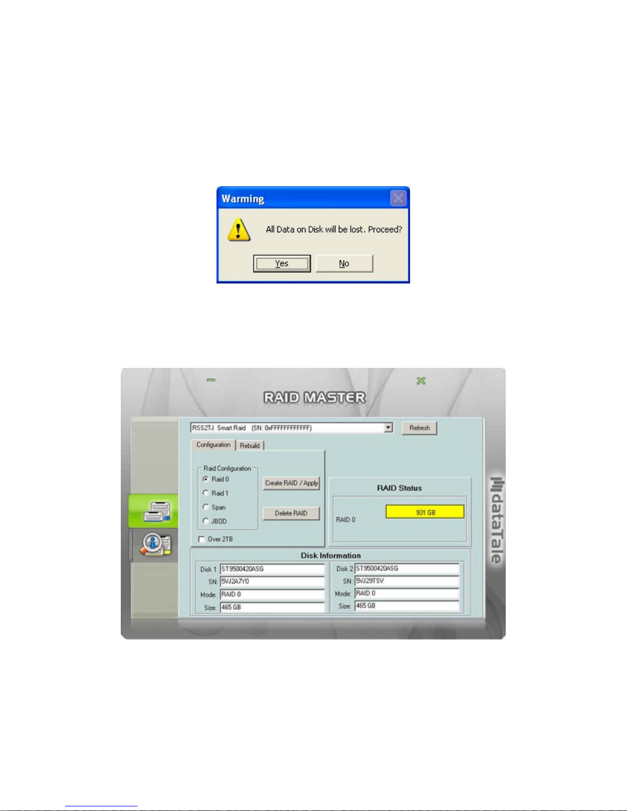
the HDD(s) is/are over 2TB, remember to check the “Over 2TB” option under the
“Configuration” option tab. Please see “Over 2TB” section under Q&As for more
information. Please review the “DISK VOLUME OVER 2TB” section of the User’s
Manual for OS support information.
2. Once selected, the RAID MASTER will give an alert popup window stating “all
data on disk will be lost. Proceed?”. Click on “Yes” icon to confirm.
3. Once confirmed, the RAID MASTER will begin processing the chosen RAID
Mode onto the chosen HDD(s). Once the process is completed, the “RAID
Status” and “Disk Information” should reflect the newly assigned RAID mode.
The RAID Unit is now ready to be used under the preferred RAID Mode!
19
Page 20
CHANGING THE MOST RECENT ASSIGNED RAID MODE
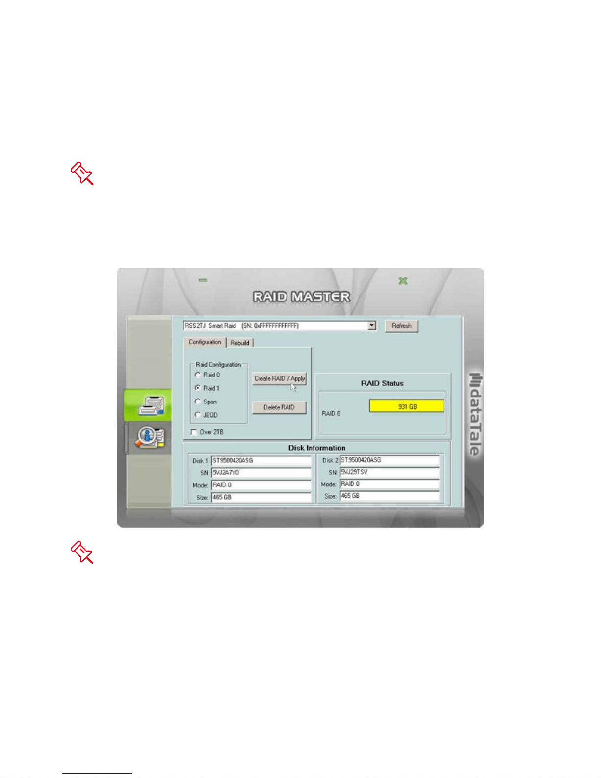
To change the most recent assigned RAID Mode for the inserted HDD(s) of the RAID
Unit, please complete the following steps:
Changing the RAID Mode will delete all data stored on the HDD(s). If you have
important saved data in the hard drives, backup all data before changing the RAID
Mode.
1. Under the “Configuration” option tab, select the RAID mode prefer changing to
and click the “Create RAID/Apply” icon.
If the host can support more than 2TB HDD(s) storage capacities and the HDD(s)
is/are over 2TB, remember to check the “Over 2TB” option under the “Configuration”
option tab. Please see “Over 2TB” section under Q&As for more information. Please
review the “DISK VOLUME OVER 2TB” section of the User’s Manual for OS support
information
20
Page 21

2. Once selected, the RAID MASTER will give an alert popup window stating, “all
data on disk will be lost. Proceed?” Click on “Yes” icon to confirm.
3. Once confirmed, the RAID MASTER will begin processing the chosen RAID
Mode onto the chosen HDD(s). Once the process is completed, the “RAID
Status” and “Disk Information” should reflect the newly assigned RAID mode.
The chosen HDD(s) RAID is/are now ready to be used under the new preferred
RAID Mode!
21
Page 22
DELETING AN ASSIGNED RAID MODE
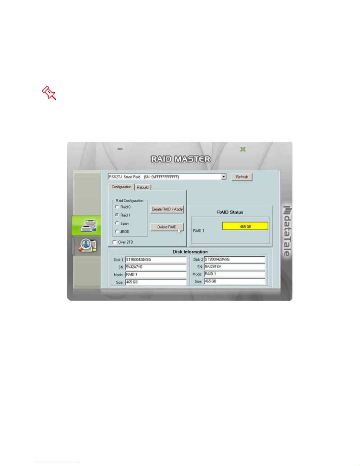
To delete an assigned RAID Mode for the inserted HDD(s) of the RAID Unit, please
complete the following steps:
Deleting a RAID Mode will delete all data stored on the HDD(s). If you have
important saved data in the hard drives, backup all data before deleting the RAID Mode.
1. Under the “Configuration” option tab, click the “Delete RAID” icon to change the
HDD(s) into JBOD (Non RAID) disks.
22
Page 23
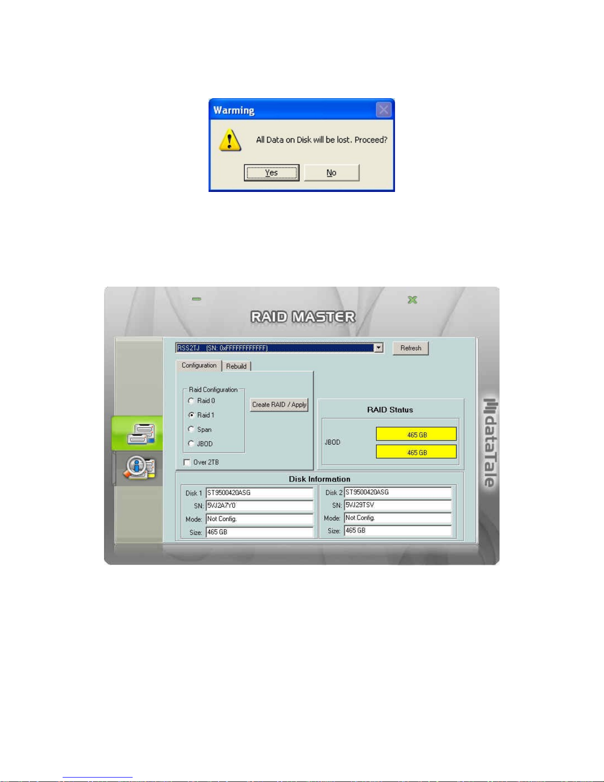
2. Once selected, the RAID MASTER will give an alert popup window stating, “all
data on disk will be lost. Proceed?” Click on “Yes” icon to confirm.
3. Once confirmed, the RAID MASTER will begin erasing the old RAID Mode for the
chosen HDD(s). Once the process is completed, the “RAID Status” and “Disk
Information” should reflect the chosen HDD(s) as JBOD (Non RAID). The
chosen HDD(s) RAID is/are now ready to be used under the new preferred RAID
Mode!
23
Page 24
REBUILD
If one of the HDDs fails, the Disk LED will become red, and the rebuild function can be
set up under RAID 1 mode. To setup Rebuild under RAID 1 mode, please complete the
following steps:
The use of identical HDDs from the same manufacturer, with the same capacity
and RPM is highly recommended.
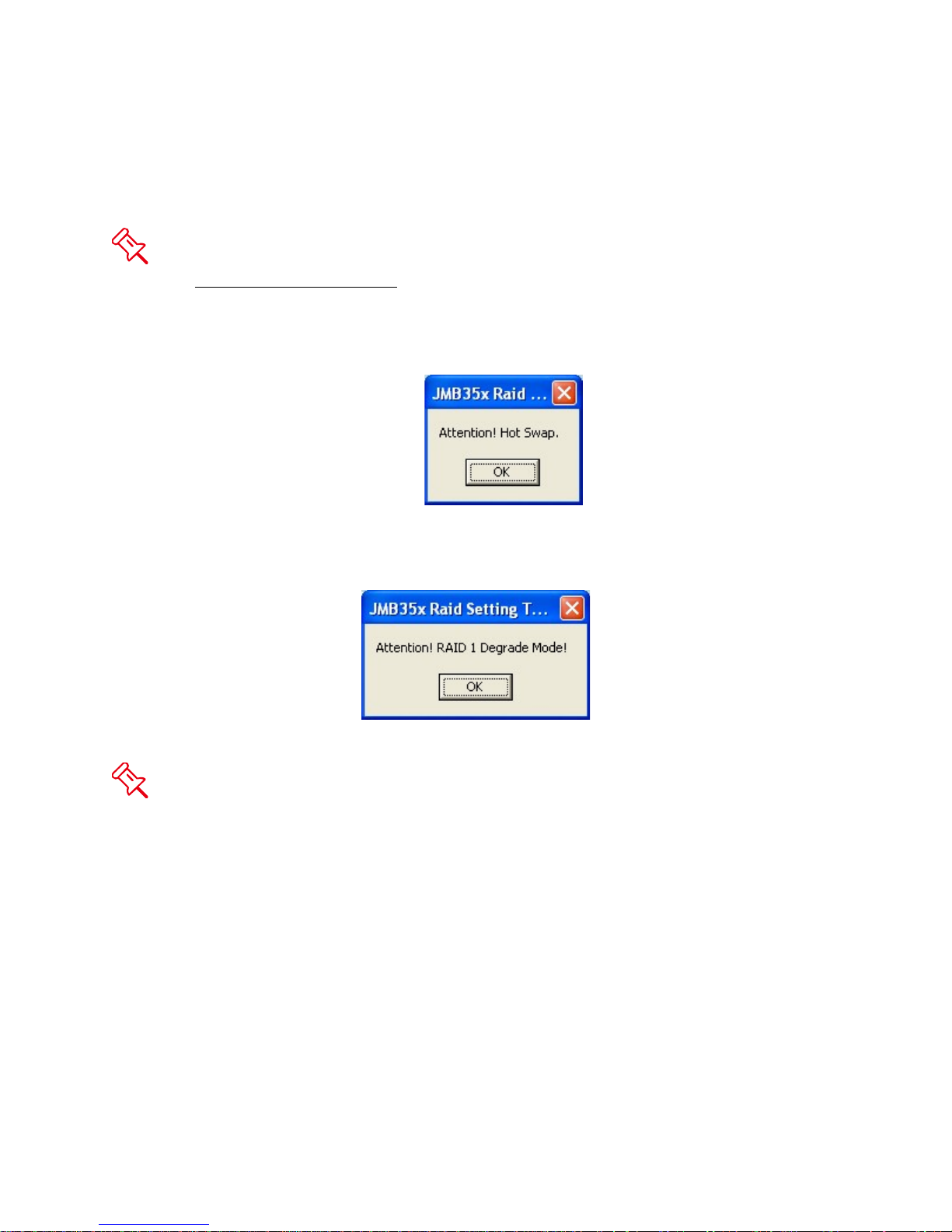
1. When the failed HDD is removed, a popup window stating “Attention! Hot Swap”
will appear. Click on “Ok” icon to continue.
2. Another popup window will appear stating, “Attention! RAID 1 Degrade Mode”.
Click on “Ok” to continue.
When one of the HDD has failed, the Disk LED will become red. However, no
warnings will appear on RAID MASTER to notify the user. Please pay attention to the
Disk LEDs at all times.
24
Page 25
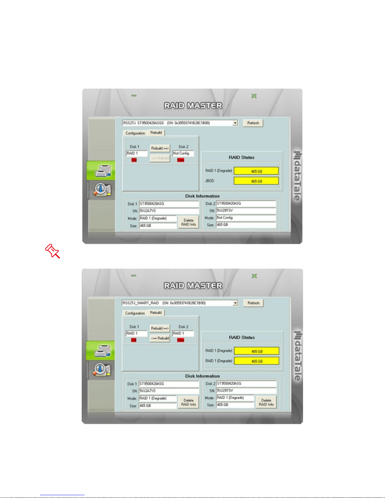
3. Then, the “Rebuild” option should appear. Continue by replacing the failed
HDD with a functional HDD or inserting a New HDD in place of the one removed.
The New HDD will show up as red “New” and “Not Config”. To rebuild the New
HDD (the new functional HDD) with the data from the Old HDD (the remaining
functional HDD) sector by sector, click on the “Rebuild ==>” icon.
The New HDD may be inserted into either Disk 1 or Disk 2, because the Rebuild
feature can be performed in either direction.
4. A popup window stating, “Copy Data From Disk 1 to Disk 2. All data in Disk 2 will
be lost. Continue?” Click on the “Yes” icon to confirm.
25
Page 26
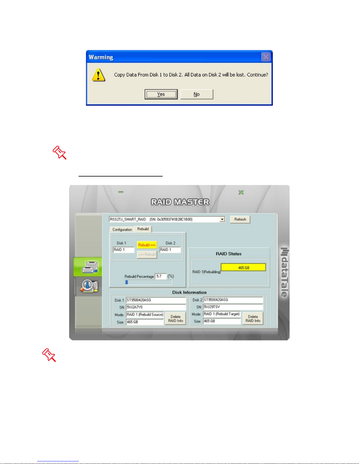
5. During the rebuild, a “Rebuild Percentage” status window will appear and the
information under “RAID Status” and “Disk Information” sections should reflect
the same.
If data is accessed while the chipset is processing the Rebuild task, the speed
of data access may vary or decrease. Hence, data access of the HDD(s) during
Rebuild is highly not recommended.
Even if the RAID Unit loses connection to the host, the Rebuild will continue. If the
RAID Unit is powered off, the RAID Unit will retain the Rebuild status in its memory.
When the RAID Unit is powered “on” again, the Rebuild process will resume from the
previous status.
6. After the rebuild is completed, data from Old HDD will be copied onto the New
HDD under RAID 1 mode.
26
Page 27
The Rebuild feature is only available under RAID 1 mode. If the “Rebuild” option
tab is selected under any other RAID mode, a popup window will appear stating,
“Attention! There should be two disks with at least one RAID 1 disk for Rebuild Mode.”
27
Page 28
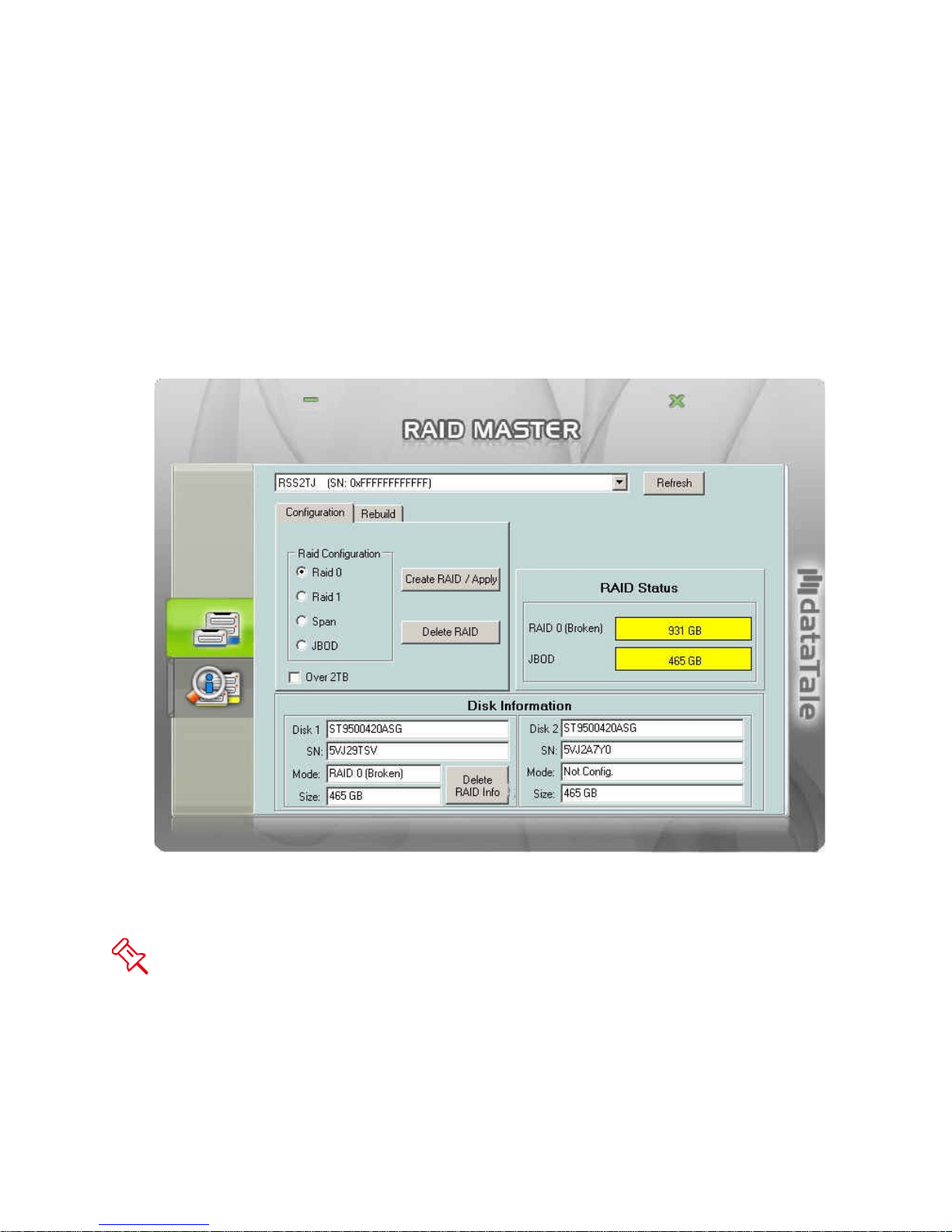
MIXED RAID STATUS
When a New HDD has been formatted with a certain RAID mode in another RAID Unit
(specifically DataTale AIR) and is placed into the current RAID Unit along with an
existing HDD, a “Mixed RAID” status will result. Under this circumstance, the New HDD
can be re-formatted as JBOD (Non RAID) mode. To do so, please complete the
following steps:
1. The New HDD will appear as “RAID 0 (Broken)”, or other variations depending
on the situation for other RAID modes. The existing HDD will appear as “JBOD”
for individual HDD, or other variations depending on the situation for other RAID
modes.
2. To erase the previous formatting in the New HDD, click the “Delete RAID Info”
icon under “Disk Information”.
“Delete RAID Info” will erase all data stored on the New HDD. If you have
important saved data in the New HDD, backup all data before selecting “delete RAID
Info”.
28
Page 29
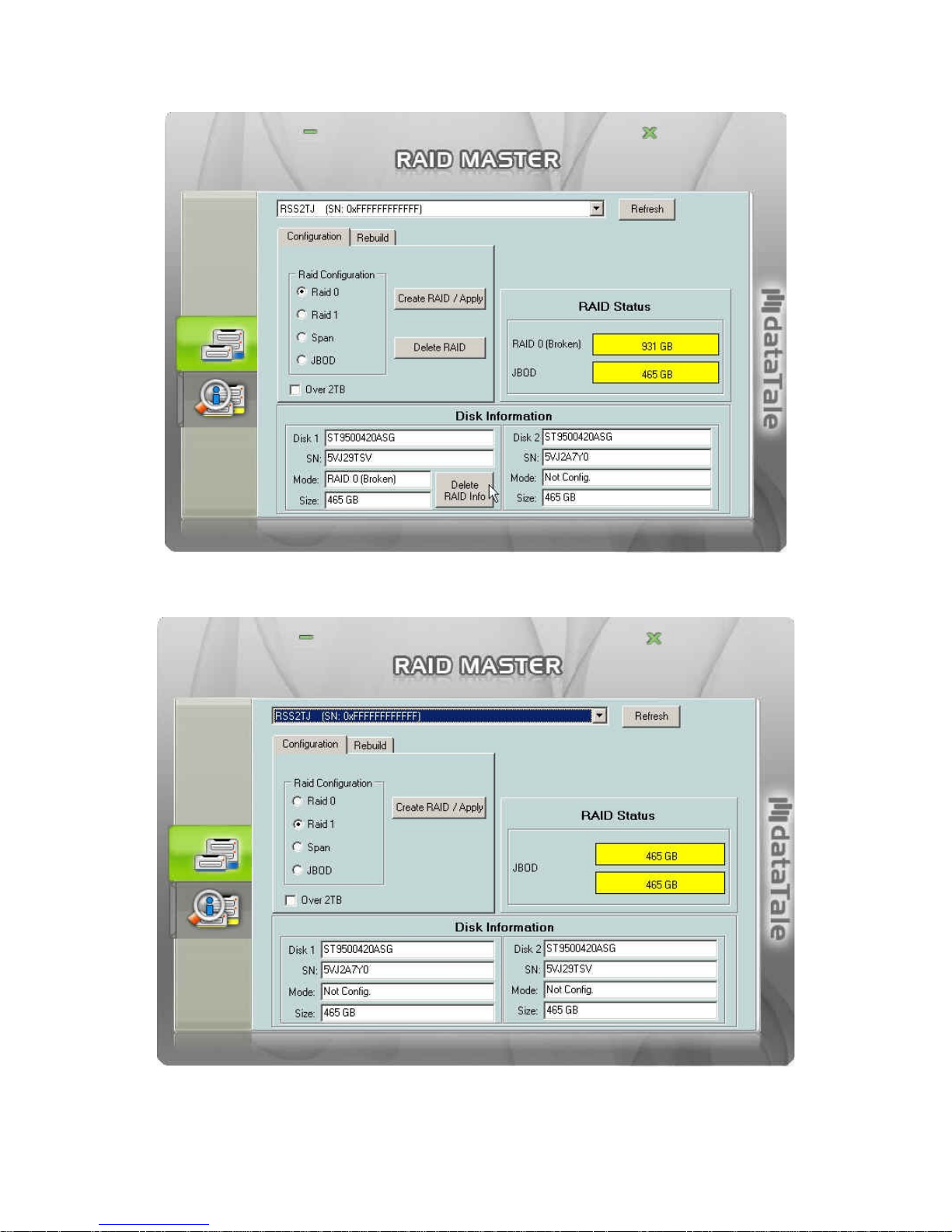
3. Once completed, the New HDD is ready to be used as JBOD or combined with
the existing HDD under a chosen RAID mode.
29
Page 30
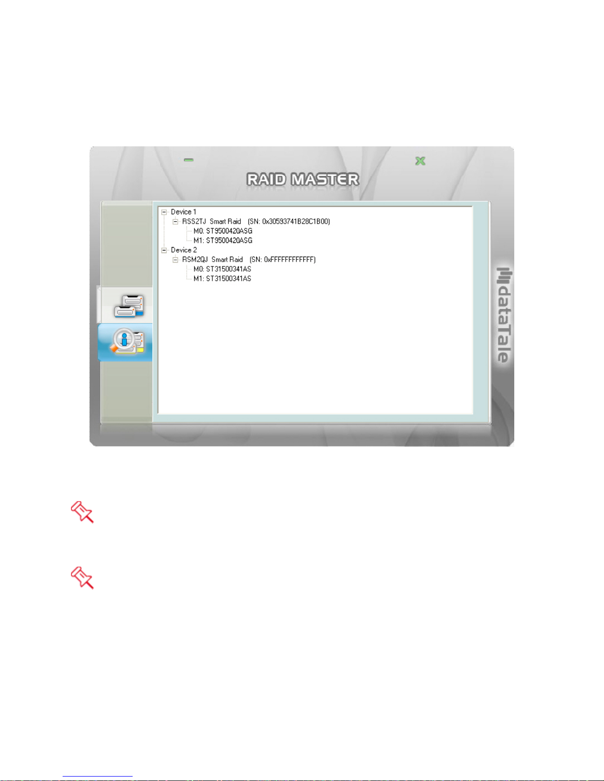
DEVICE INFORMATION
To retrieve Device Information for the inserted HDD(s) of the RAID Unit(s), please
connect the RAID Unit(s) to the host and open the RAID MASTER. Once connected,
click on the second sub-menu icon (bottom) to see the information:
The connected RAID Unit(s) information with Device model of the RAID Unit(s), and
serial numbers of each inserted HDDs.
Because the RAID MASTER can manage “more than one unit of the RAID Unit”,
each RAID Unit connected to the host computer will reflect as “Device __” and in
numbering order “Device 1, Device 2, …” respectively.
Due to chipset configuration, the Device List will reflect the HDDs as “M0 and M1”
for “Disk 1 and 2”, respectively.
30
Page 31
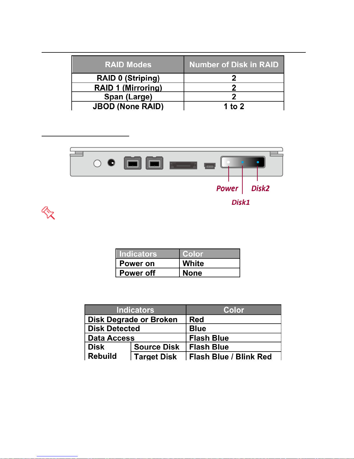
NUMBER OF DISKS SUPPORTING EACH RAID MODE
LED INDICATORS
The LED Panel has a thin plastic film for protection. It may be removed if prefer
having a clearer view.
POWER LED
DISK LEDS
31
Page 32
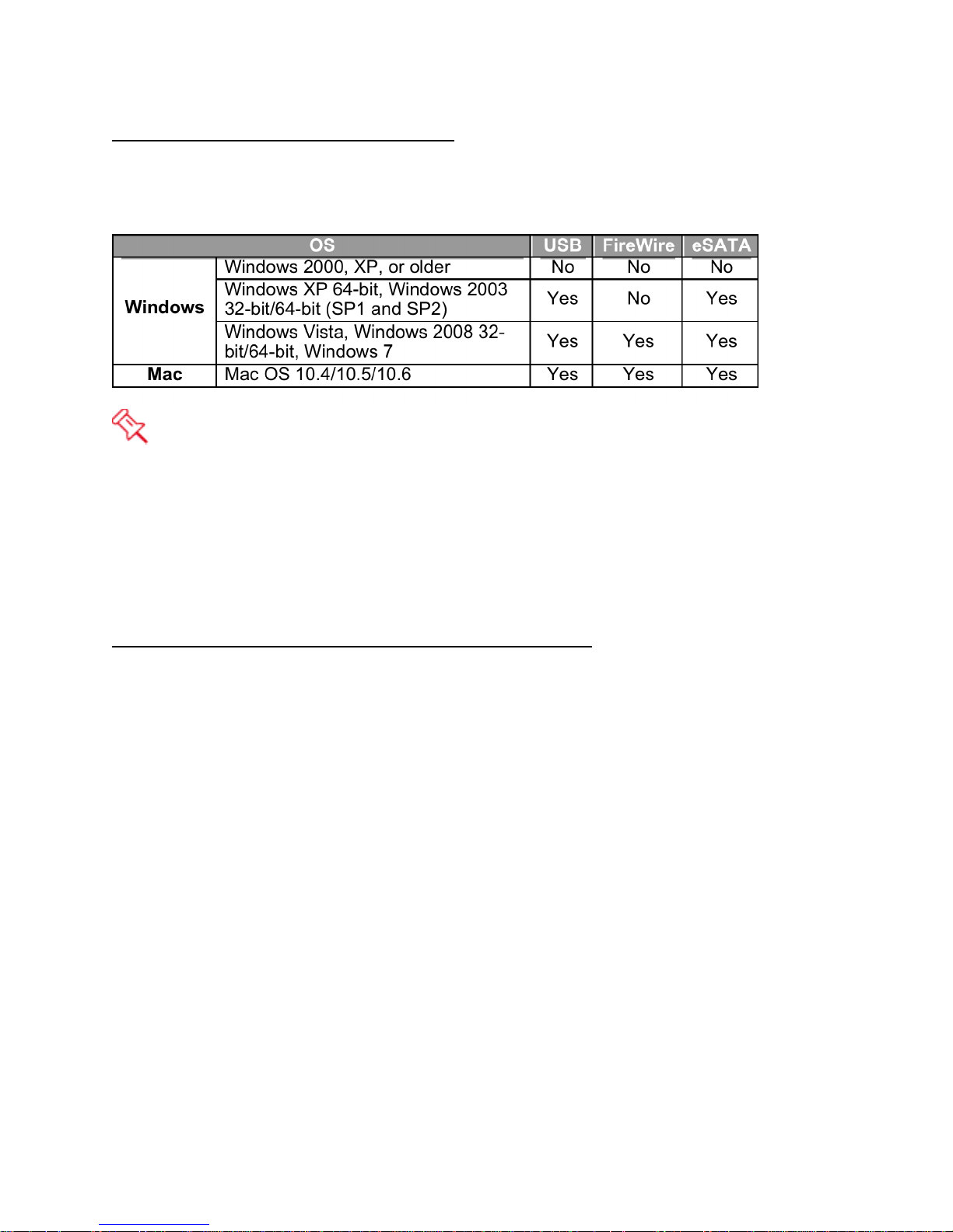
DISK VOLUME OVER 2TB
Windows 2000, XP & MAC OS 10.2 (& older) do not support partitions larger than 2TB+
or higher. In order to support 2TB+ partitions, you must use Windows Vista, 7, or Mac
OS 10.3 or higher. Please note that Windows XP 64-bit and Windows 2003 support
2TB+ when using USB & eSATA, but are limited to 2TB when using FireWire.
If the OS does not support over 2TB, you can still use the RAID Unit by NOT
checking the “Over 2TB” option under the “Configuration” option tab. The RAID
MASTER should automatically re-adjust the available HDD(s) storage capacity and
format the chosen RAID mode under 2TB. Please see “Over 2TB” section under Q&As
for more information.
SAFE REMOVAL OF THE RAID UNIT
Safe removal of the RAID Unit from the host controller is highly recommended,
especially when switching interfaces. In order to safely remove your RAID Unit from the
host controller, you would need to eject the device on your host controller system.
32
Page 33
RAID MODES
A Redundant Array of Independent (or Inexpensive) Disks (RAID) is a system that
utilizes multiple hard drives to share or replicate data among the disks. The benefit,
depending on the selected RAID Mode (combinations of disks), is one or more of
increased data integrity, fault-tolerance, throughput or capacity when compared to
single drives.
Deleting the current partition prior to changing RAID modes is highly
recommended.
Using identical HDDs with the same capacity and RPM, and from the same
manufacturer are highly recommended for best capacity utilization.
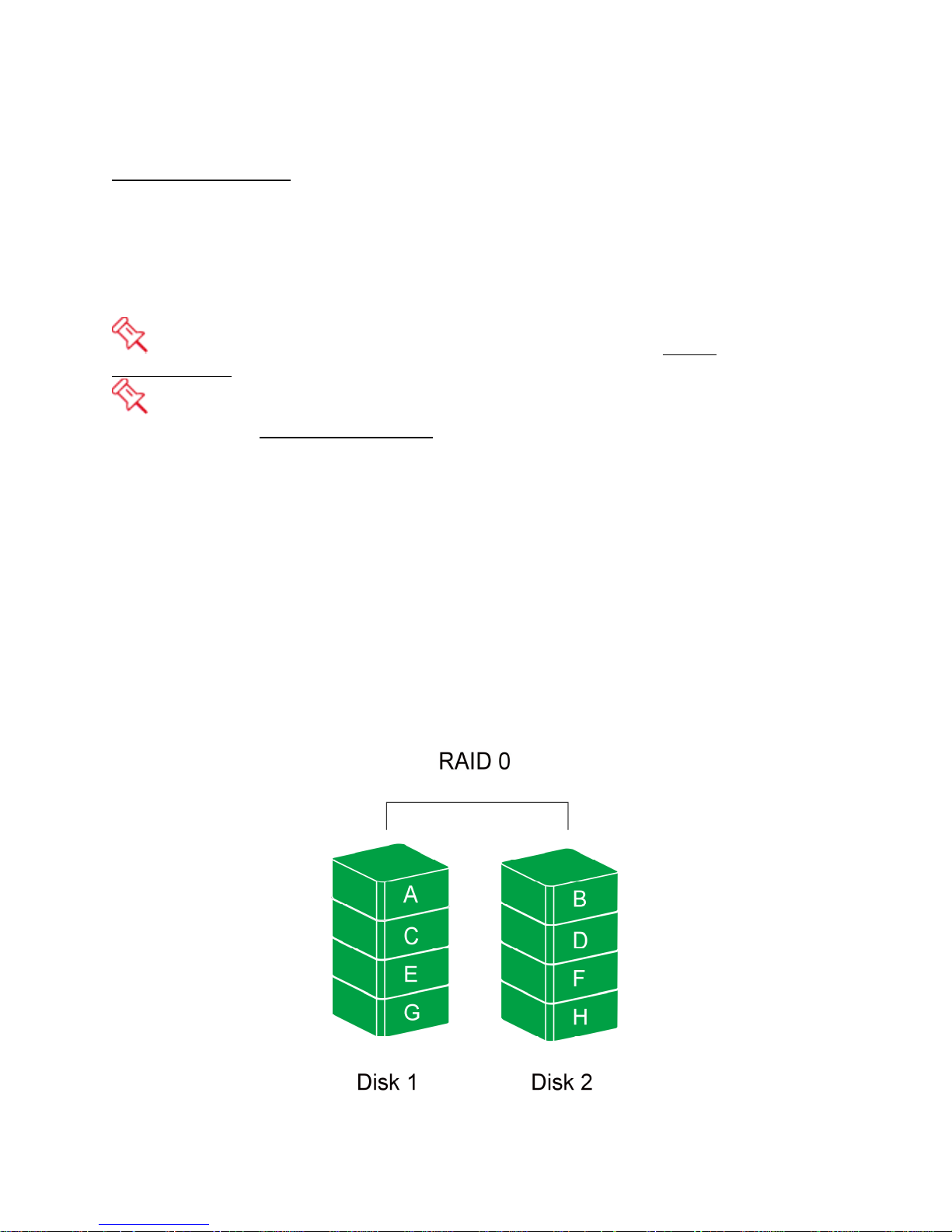
RAID O (STRIPING)
RAID 0 (Striping) is a performance-oriented, non-redundant data mapping technique. It
combines multiple hard drives into a single logical unit. Instead of seeing several
different hard drives, the operating system sees only one large drive. Striping splits
data evenly across two or more disks simultaneously, dramatically increasing
performance.
Striping can be implemented in disks of differing sizes, but the storage space added to
the array by each disk is limited to the size of the smallest disk. Although Striping is an
easily implemented, simple configuration, Striping should never be used for mission
critical applications. The speed of operation is excellent in comparison to other RAID
modes.
33
Page 34
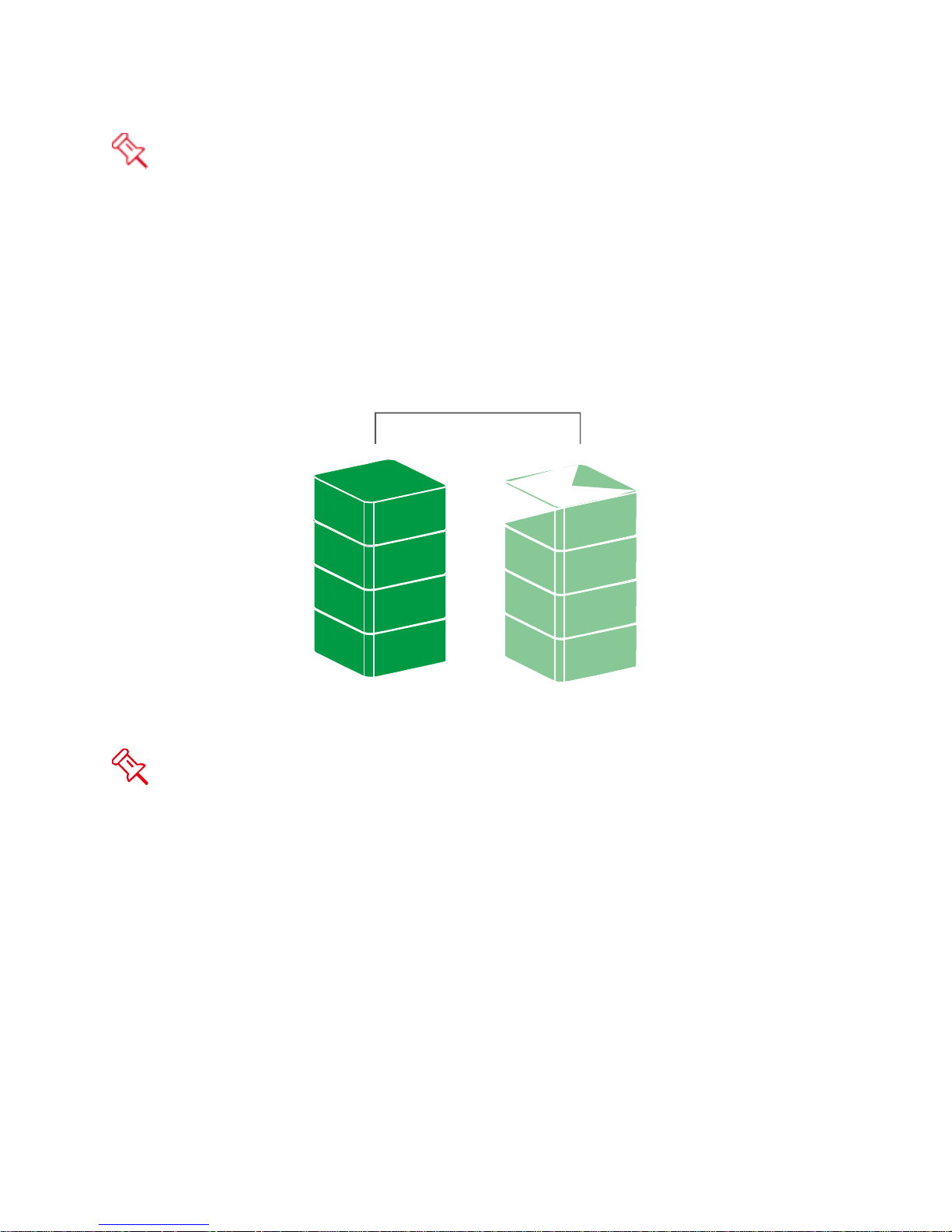
In Striping mode, if one disk in the RAID Unit fails, all data in installed disks will be
RAID 1
Disk 1
Disk 2
A
B
C
D
A
B
C
D
lost.
RAID 1 (MIRRORING)
RAID 1 (Mirroring) consists of at least two drives storing duplicate copies of the same
data. In this mode, the data is simultaneously written to two disks. Thus, the storage
capacity of a two-disk array is combined into a single disk and the capacity is limited to
the size of the smallest disk.
In Mirroring mode, if one of the disks fails, either source or backup, the data is still
available. However, if the Old disk fails during the Rebuild process, the data in both
disks will be lost.
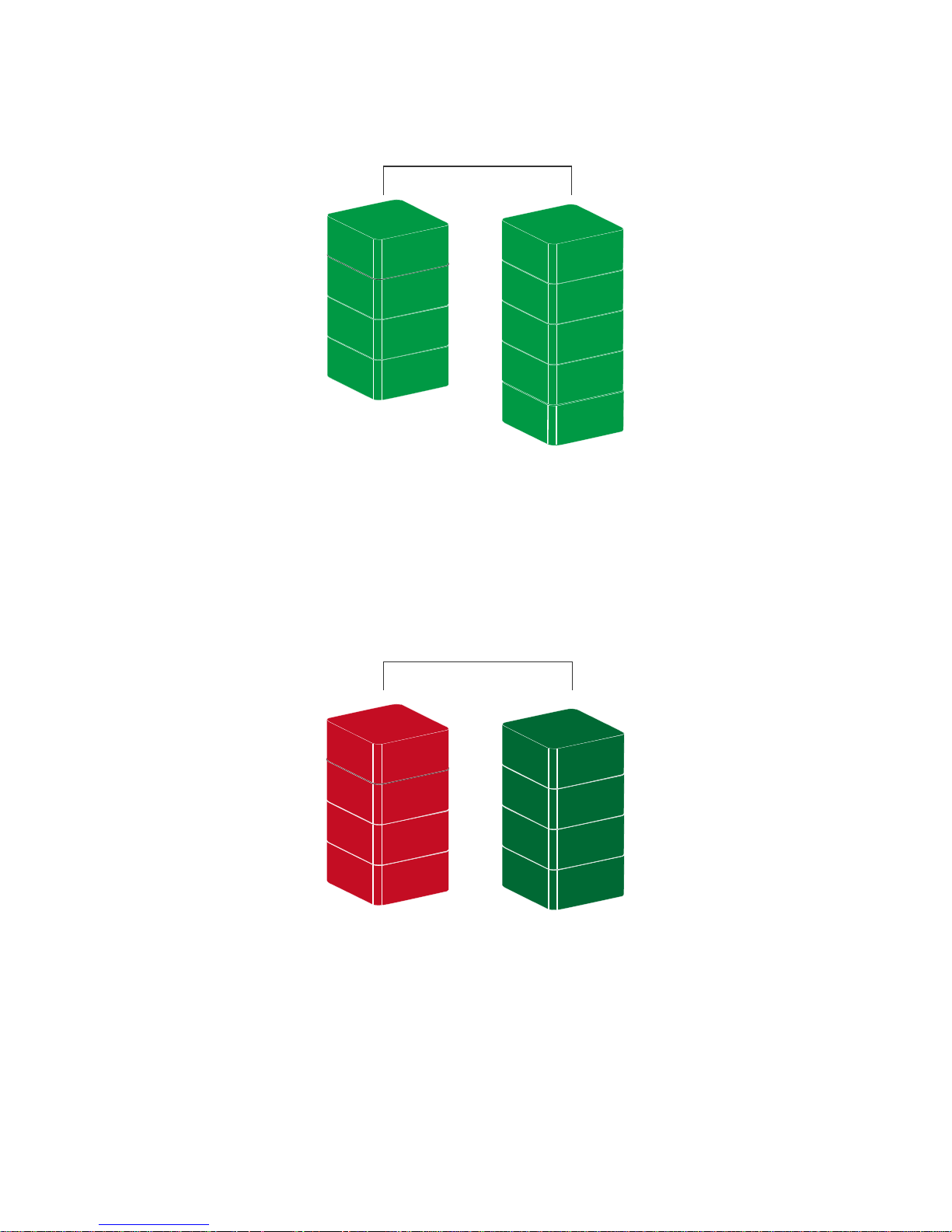
SPAN (LARGE)
Spanning provides another maximum capacity solution, which some call it as “Large”.
Spanning combines multiple hard drives into a single logical unit. Unlike Striping,
Spanning writes data to the first physical drive until it reaches full capacity. When the
first disk reaches full capacity, data is written to the second physical disk. Spanning
provides the maximum possible storage capacity, but does not increase performance.
34
Page 35
SPAN
Disk 1 Disk 2
A
B
C
D
E
F
G
H
F
JBOD (NON RAID)
JBOD
Disk 1
Disk 2
A
B
C
D
Ä
ß
Ç
µ
Just a Bunch of Disks (JBOD) refers to a group of hard drives. In JBOD, the number of
logical drives is equal to the number of physical drives. This mode allows the RAID Unit
to operate as a multi-disk storage enclosure, but provides no data redundancy.
35
Page 36

Q&As
GENERAL
Q: How do I choose the proper RAID mode for my RAID Unit based on the tasks I need
to perform?
A: Since the RAID Unit is a “Mass Storage” device, which means its size capacity is
sufficient for data management, the different RAID mode settings can help you
administer the enormous data storage from the HDDs combination. It is highly
recommended to choose the RAID mode based on what is the essential factor to
complete your task. The most common three factors are size capacity, speed, and data
protection. For example, if using the RAID Unit to simply watch films for enjoyment or
for storage, the JBOD and SPAN modes are perfect because they can maintain decent
speed and still have a large storage capacity. If the work requires instant and
continuous backup of data such as for a writer or editor, then RAID 1 would be the best
choice. However, if immediate data access is required such as business professionals,
RAID 0 would be more appropriate.
DAISY CHAIN
Q: Because there are two (2) FireWire ports on the RAID Unit, I connected them to my
other two (2) external devices. Why can’t I see these additional external devices on my
host? I’m using the USB connection from the RAID Unit to my host.
A: In order for the “Daisy Chain” feature to work properly on the RAID Unit, one of the
FireWire ports need to be connected to the host, and the other one can be connected to
an external device. The computer will not recognize different interfaces if they are all
used at the same time.
OLD HDDs
Q: My old hard disk(s) have data inside. Will the stored data still be recognizable if I
just install them into the RAID Unit?
A: Please backup all existing data from the old hard disk(s) before installing them into
the RAID Unit. Once the old hard disk(s) are inserted and setup for a chosen RAID
mode, the RAID MASTER will automatically re-format the disks and all the old data will
be lost.
HDD SIZE
Q: Can I use one 2.5” 9.5mm thick SATA HDD, and one 2.5”12.5mm thick SATA HDD
inside the same RAID Unit? Will the RAID Unit be able to recognize them?
A: Yes, the RAID Unit can support both 9.5mm and 12.5mm thick 2.5” HDDs.
36
Page 37
HDD CAPACITY
Q: I would like to format my hard drives with the FAT (a.k.a. File Allocation Table)
format, which can be read and written by both Mac and PC. Is there any limitation on its
capacity?
A: Yes, please check the table below for reference.
File System NTFS FAT32 FAT (Format by
Win2000 / WinXP)
Capacity
Limitation
Vista: 16384TB
XP: 2TB
Windows: 32GB
Mac: 2TB
4GB 2GB
FAT16
DISCREPANCY IN REPORTED & ACTUAL SIZE CAPACITY
Q: If I have a 750GB HDD, why does the RAID Unit only recognized the HDD available
space as to be less than 750GB?
A: In the hard drive industry the partitioned size will be less than the printed capacity on
the label. This is consistent whether it is Western Digital, Seagate, Samsung, etc. For
example, a 1TB hard drive will have a formatted capacity of approximately 932GB. This
is due to the fact that computers calculate capacity based on 1024 bytes/kilobyte, while
the hard drive calculation is based on 1000 instead of 1024. Hard drive manufacturers
define a megabyte as 1,000,000 bytes and a gigabyte as 1,000,000,000 bytes, which is
a decimal (base 10) measurement. Computers define a megabyte as 1,048,576 bytes
and a gigabyte as 1,073,741,824 bytes. These are binary (base 2) measurements. This
is why the two different industries will report different capacities for the same drive. The
number of bytes is the same, but a different number of bytes is used to make a
megabyte and a gigabyte.
REBUILD
Q: Does the RAID Unit have to be connected to the host computer when it is in rebuild
mode?
A: No, it does not have to be. The RAID Unit can support offline rebuild, which means it
can perform the rebuild function without being connected to a host computer.
RAID MASTER: CONNECTION RESTRICTION
Q: Is there any connection restrictions for the RAID MASTER?
A: Yes, the RAID MASTER can only be operated via USB 2.0 or FireWire 800. If you
choose to use eSATA for data transferring, please set up the RAID configuration via
USB or FireWire first.
37
Page 38
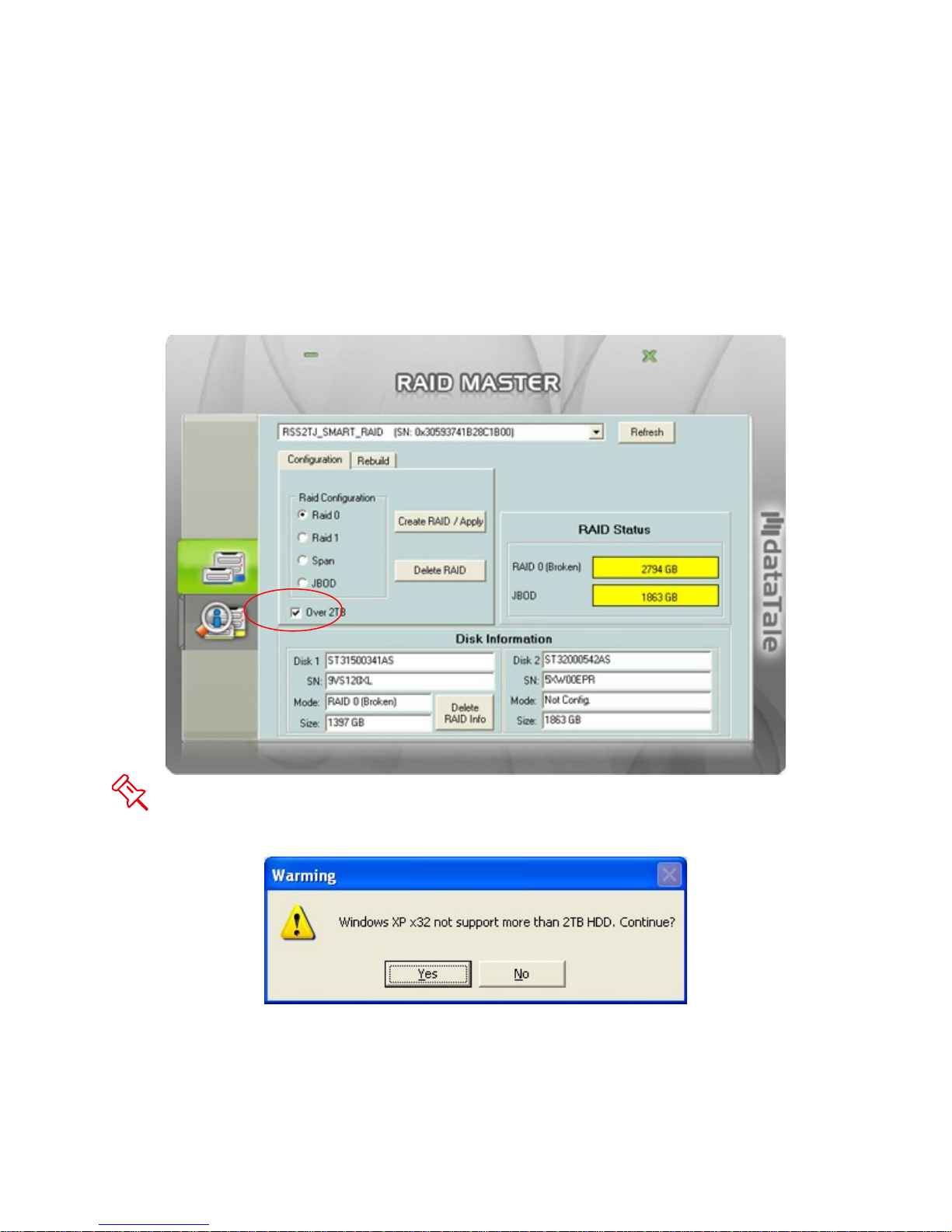
OVER 2TB
Q: What is the “Over 2TB” option for under PC’s version of RAID MASTER?
A: The HDD(s)’ storage capacity can affect RAID Unit’s operation depending on your
host’s PC OS. Some older PC OS can only function the RAID Unit under a particular
size limitation (please see “DISK VOLUME OVER 2TB” for more information). If the
host can support more than 2TB HDD(s) storage capacities and the HDD(s) is/are over
2TB, check the “Over 2TB” option under the “Configuration” option tab. Because the
Unit requires OS 10.4 and above for MAC, which automatically supports over 2TB, the
“Over 2TB” option would not appear under the RAID MASTER for MAC.
This popup window may appear if the host’s OS cannot support over 2TB of HDD
storage capacity, similar to the picture shown below. Click on the “Yes“ icon to
continue.
38
Page 39
LINUX
Q: Can I use this RAID system under Linux OS?
A: Yes, but the RAID System must first be set up under Windows or MAC OS via USB
2.0 or FireWire connection before using it under Linux OS.
Regarding Over 2TB support, please see the table below:
OS 1394 USB SATA
Linux Fedora Core 8 32-bit No No Yes
Linux Fedora Core 8 64-bit No No Yes
Linux Fedora Core 10 64-bit No Yes Yes
Linux Fedora Core 11 32-bit No Yes Yes
Linux Fedora Core 12 64-bit Yes Yes Yes
Linux Fedora Core 13 32-bit Yes Yes Yes
Q: Can I use external bootup under Linux OS?
A: Yes, but only via eSATA connection.
39
Page 40
APPENDIX
Model Name RS-S2TJ
Interface
Connector eSATA x 1, USB 2.0 x 1, 1394b x 2
HDD Support
Data Transfer Speed
RAID Level
LED Indicators Power / Connection / Health / Access / Rebuild
System Material Aluminum case with plastic parts
Power Supply
Dimension 155 (L) x 155 (W) x 22.5 (H) mm
Weight (without HDD) 260 grams
Certification CE, FCC
*Identical HDD recommended – same manufacturer,
JBOD (Non RAID), RAID 0 (Striping), RAID 1 (Mirroring),
Or bus power from host via FireWire 800 (1394b) cable
USB 2.0 / eSATA / FireWire 800
2.5” SATA HDD*
capacity and RPM (9.5mm or 12.5mm)
eSATA: up to 3Gbit/sec
1394b: up to 800Mbit/sec
USB 2.0: up to 480Mbit/sec
Span (Large)
Input: AC 100~240V
Output: DC +5V/2A
40
 Loading...