

Page 1
UM-0071-A0
Page 2
UM-0071-A0
Page 3

Getting Started
with
DT800
dataTaker
UM-0071-A0
UM-0071-A0
dataTaker
All other brand and product names are trademarks or registered trademarks of their respective holders.
is a registered trademark of
Copyright © 2000
dataTaker Pty Ltd
dataTaker Pty Ltd.
Page 4

About this User’s Guide
Welcome to
This quick-start user’s guide is a tutorial that uses step-
by-step instructions, simple explanations and simple
examples to get you up-and-running with your
dataTaker
Getting Started with DT800 dataTaker.
DT800 data logging and acquisition system.
If You Never Read Manuals
If you’re new to
manual you must read.
It won’t take you long and, just like any good
investment, the time you spend working through the
information provided here will be repaid to you many
times over as you use your
dataTaker
, this user’s guide is one
dataTaker
.
Which User Are You?
This guide is primarily designed for
users. If you work through all the steps in the order in
which they’re presented, you can be confident that
you’ll learn enough about data acquisition and
logging, your DT800 data logger, and the software
you use to communicate with it to satisfy your needs for
a very long time.
If you’re an
through this guide noting only the major instruction
steps. These are designated by the arrow icon shown
in the example immediately below. Instructions tagged
in this way form a quick guide to prompt experienced
users.
➲
This is an example of a major instruction
experienced
dataTaker
new
dataTaker
user, you can skim
step. Instructions tagged like this summarize
what follows, and experienced users may need
to read only these.
If you’re an experienced
in a hurry, you can go directly to the
User’s Manual
supplied with your DT800.
dataTaker
and computer user
DT800 dataTaker
More Information
Your DT800 is capable of extremely sophisticated data
acquisition and logging. So if you want more
information than this guide provides, refer to the
DT800 dataTaker User’s Manual
new DT800, or other DT800 documentation available
separately (ask your
www.datataker.com).
In any case, at your leisure, we recommend that you
browse through the
get an overview of everything your DT800 is capable
of.
dataTaker
DT800 dataTaker User’s Manual
supplied with each
distributor, or visit
to
This Guide Assumes…
• Microsoft® Windows® 95, Windows® 98,
Windows
installed on your computer and works reliably.
• You are familiar with basic Microsoft Windows
operations and the concepts of COM ports and
Windows communications.
If you are inexperienced with Windows, refer to
Microsoft publications such as
User’s Guide
Windows
Windows reference books available.
®
2000 or Windows NT® is correctly
Microsoft Windows
and
Getting Started with Microsoft
, or any of the many third-party
What Now?
Go to “Contents” on page 5 for a bird’s-eye-view of
what’s in store, then begin working through this tutorial
starting with Chapter 1 “Acquisition? Logging?…” on
page 6.
Extras
All readers will benefit from the “Extras”
included with many of the topics. Extras
are additional information intended to
supplement each topic. You don’t need to
read the Extras to be able to work through this guide,
although we do recommend you read them at some
time because they contain valuable background
information that will enhance your “big picture” of
data acquisition, data logging and the DT800
dataTaker
UM-0071-A0
4
system.
Getting Started with DT800
dataTaker
Page 5

Contents
About this User’s Guide......................... 4
Contents................................................ 5
CHAPTER 1
CQUISITION
A
1-1 Important Concepts.........................................6
1-2 Important Terminology ..................................11
CHAPTER 2
SET UP
2-1 Checklist .....................................................13
2-2 Power the DT800 .........................................14
2-3 Make the Hardware Connection ....................14
2-4 Attach a Sensor............................................15
CHAPTER 3
SET UP
3-1 Install DeLogger............................................16
3-2 Start DeLogger .............................................18
3-3 Make the Software Connection ......................19
3-4 Verify the Connection....................................20
CHAPTER 4
A Q
4-1 The Big Pictures............................................22
4-2 DeLogger’s Main Toolbar ..............................26
4-3 DeLogger’s Menus........................................27
4-4 More Important Concepts and Terminology .....28
THE HARDWARE
THE DELOGGER SOFTWARE
UICK OVERVIEW OF DELOGGER
OGGING
? L
?…
CHAPTER 8
SEE YOUR DATA — MIMIC WINDOW
8-1 DeLogger’s Mimic Window........................... 49
8-2 Display Returned Data in a Meter .................. 50
8-3 Replay a File to a Meter................................ 51
8-4 Add a Graphic............................................ 52
8-5 Disconnect ..................................................53
CHAPTER 9
EXTEND YOUR PROGRAM
9-1 Reconnect ................................................... 54
9-2 Change Schedule A’s Rate............................ 55
9-3 Add a Channel Label ................................... 55
9-4 Add More Channels to Schedule A ................56
9-5 Re-Send the Program .................................... 59
9-6 Reassign the Form, Chart and Mimic Windows 59
9-7 DeLogger’s Text Window.............................. 60
9-8 Return Data to the Text Window ....................61
9-9 Add an Alarm .............................................63
9-10 Add Schedule B to the Program ..................... 64
CHAPTER 10
OTHER THINGS YOU CAN DO WITH
DELOGGER
10-1 Unload Logged Data .................................... 66
10-2 DeLogger’s Spreadsheet Window .................. 68
10-3 Load Data into a Spreadsheet........................ 69
10-4 Finish Off.................................................... 69
10-5 What’s Next?.............................................. 69
CHAPTER 5
OUR FIRST PROGRAM
Y
5-1 DeLogger’s Program Builder Window .............31
5-2 Create a Program.........................................33
5-3 See What You’ll Send...................................36
5-4 Send the Program.........................................36
CHAPTER 6
SEE Y
6-1 DeLogger’s Form Window.............................38
6-2 View the Returned Data.................................41
6-3 Set the DT800’s Date and Time......................42
CHAPTER 7
SEE Y
7-1 DeLogger’s Chart Window ............................43
7-2 Chart the Returned Data................................48
Contents
OUR DATA
OUR DATA
— F
ORM WINDOW
— C
HART WINDOW
Index .................................................. 70
5
UM-0071-A0
Page 6

CHAPTER 1
A
CQUISITION
? L
OGGING
?…
You really can’t avoid it — there’s just no way you can
afford to short-cut this chapter.
It’s quick to read, and it will make you comfortable
with some fundamental
logging concepts, terminology and conventions.
So read on…
dataTaker
data acquisition and
1-1
IMPORTANT CONCEPTS
Your first job as you work through this tutorial-in-theform-of-a-user’s-guide is to familiarize yourself with the
following concepts.
Data Acquisition versus Data Logging
Data acquisition and data logging are NOT the same.
Traditionally, data
regular collection of data — scanning sensors, making
instantaneous measurements, then feeding these to a
recorder or computer.
Data
logging
• It’s considered by some to be simply making a
permanent record of data that has been collected:
printing or plotting it, writing it on a sheet of paper,
or storing it on a computer’s hard disk or in
electronic memory.
• Others perceive data logging as the total operation
of collecting data and making a permanent record
of it. Therefore, they see data acquisition as part of
data logging.
Now, with
two terms has become even more blurred because the
dataTaker
(and much more) in a single instrument about the size
of a house brick.
So, when using your DT800, it’s important that you
treat acquisition and logging as two separate
functions.
dataTaker
DT800 combines acquisition and logging
acquisition
has two possible definitions:
, any distinction between these
has been defined as the
dataTaker
One of the DT800’s two basic functions is to read
sensors (that is, to measure, sample or scan sensors)
and present the values to you on a computer screen or
other display (Figure 1).
Although these readings can be used, say, to trigger
an alarm, they are temporary: the DT800 has not
recorded, stored or remembered them anywhere —
UM-0071-A0
6 Getting Started with DT800
’s Acquisition Function
dataTaker
Page 7

that is, the data has not yet been logged by the
DT800.
DT800
scans
sensors
FIGURE 1 Data acquisition
dataTaker
’s Logging Function
DT800
displays data
Alarms, actions
The second of the DT800’s two basic functions is to log
data
— that is, to record or store data (Figure 2).
Once you’ve instructed the DT800 to acquire data,
you must then issue the LOGON command (explained
later) if you want it to store the data.
DT800
displays data
Alarms, actions
DT800 saves data to
• its internal memory
• a removable memory card
• the host computer.
The DT800
The
dataTaker
acquiring data from sensors connected to it, recording
(logging) the data for later reference and analysis, and
taking action (like raising alarms or altering its
operation) based on the values it measures or
calculates.
What It Can Do
More specifically, your DT800 can perform any or all
of the following tasks:
•
acquire
measurements and forward them to a computer)
•
log
data (that is, store measurements in its own
internal memory and/or its removable memory
card)
•
convert
requirements (voltages to ºC or ºF, for example)
• carry out calculations on the measurements
(average, standard deviation, maximum,
minimum,…)
• log the converted measurements and the results of
calculations to its internal memory and/or a
removable memory card, or transfer them to a
computer
• display all of this on a computer screen
• return data directly to a computer in
is, as each measurement is made) as well as, or
instead of, logging it
• raise
Alarms can trigger outside events (turn on a
warning light or siren, for example), or make the
DT800 carry out additional tasks (scan more
frequently, stop logging, or scan and log additional
sensors, for example).
DT800 is an instrument for intelligently
data (scan sensors, make instantaneous
measurements according to your
real time
alarms
when data is outside specified ranges.
(that
You’re the Boss
Being microprocessor-based, you send instructions
(“commands” — see the Extras panel “Sending
FIGURE 2 Data logging
CHAPTER 1ACQUISITION? LOGGING?…: Important Concepts 7
Commands” on page 8) to the DT800 from a
computer running DT800-compatible software such as
DeLogger
(used later in this guide). These instructions
tell the DT800
• which sensors to read
• how often to read them
• what to do with the data.
Then you sit back and let the DT800 do the work.
UM-0071-A0
Page 8

Look, No Hands
Once you’ve set the DT800 running you can
disconnect the computer if you wish — the DT800
continues to operate as programmed because the
software which controls the logger is inside the logger
itself. This is called
stand-alone
operation.
Input Types
The DT800 lets you monitor, record and raise alarms
for readings from many types of sensors and
transducers — temperature (thermocouples,
thermistors, RTDs and solid-state sensors), pressure,
flow, strain, digital state (high or low, off or on), count,
frequency, period, voltage, current, resistance and so
on.
The DT800 measures these fundamental
parameters, from which all others are derived:
voltage
resistance
frequency
time
counts (pulses)
thermocouple reference temperature
This means that the DT800 supports many types of
inputs. For example:
voltage
resistance
current (including 4–20mA loops)
thermocouples
thermistors
RTDs (Resistance Temperature Detectors)
solid-state temperature sensors
bridges (strain gauges)
frequency
time
counts
pressure sensors
flow sensors
load cells
digital state (on/off, high/low)
You can connect many sensors — each one different
— to a single DT800 and have them scanned
whenever you choose.
Meaningful Quantities
Whatever the sensor, its raw output will be either
voltage, current, resistance, frequency, time, counts or
digital state. For example, the output from a
thermocouple is a voltage that varies according to the
temperature being measured: the thermocouple’s raw
output is volts (under 100 millivolts, actually), not
degrees Centigrade or Fahrenheit.
Then the raw output must be converted to a meaningful
quantity (to a temperature value in this example).
Depending on the type of sensor, this conversion
involves
Sending Commands
There are three ways you can send commands to
the DT800:
• from a computer connected to the DT800
• from a removable memory card — commands
loaded into a memory card can be transferred to
the DT800 and acted upon the moment the card is
inserted into the DT800’s memory card socket (this
is a handy way of configuring and programming
a remote DT800)
• using alarms (see the
Manual
UM-0071-A0
8 Getting Started with DT800
).
DT800 dataTaker User’s
terms which are beyond the scope of this guide. Just
be aware that raw measurements usually have to be
converted before they become the meaningful
quantities that are useful to you (Figure 3).
One of the features of the DT800 is that it
automatically performs these conversions for you. All
you have to do is tell the logger what
(a type T thermocouple, for example) and the
microprocessor inside the logger performs the
appropriate linearization and compensation, turning
the raw sensor output into a quantity with meaningful
units.
linearization
and possibly
compensation
type
the sensor is
dataTaker
,
Page 9
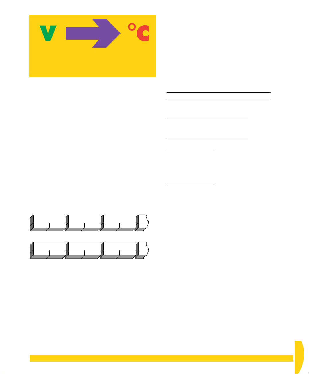
CONVERSION
BY DT800
Raw
thermocouple
output
(volts)
IGURE 3 One of the DT800’s many automatic
F
DT800
automatically performs
linearization
and
compensation
Meaningful
quantity
(degrees
Centigrade)
conversion routines
In addition, the DT800 allows you to
• define your own linearization characteristics for any
unusual sensor that is not directly supported by the
DT800
• carry out statistical operations on the measurements,
only returning the statistical results you want
(average, standard deviation, maximum,
minimum,…)
• apply other calculations or expressions you define
to process the collected data.
Time and Date Stamps
Because you’ll often want to know the time and date
each measurement was made, the DT800
automatically keeps this information along with the
measurements. This facility ensures that every reading
from every sensor can be
stamped
Example
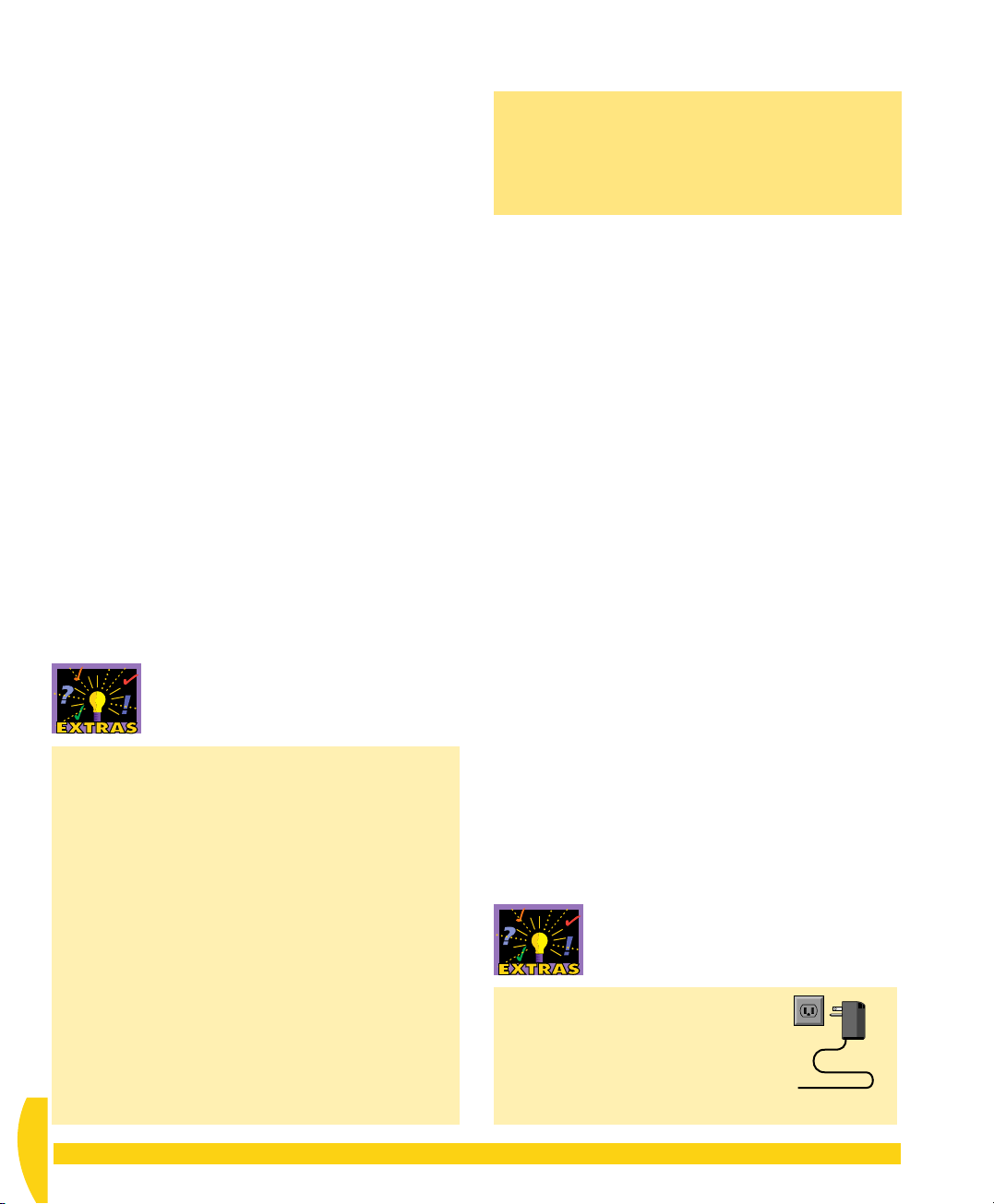
FIGURE 4 Your DT800 produces a series of
.
Measurement 1
Date 1 Time 1
163.4°C
5/6/00 9:14:00
Measurement 2
Date 2 Time 2
5/6/00 9:15:00
information “chunks”.
time-stamped
163.7°C
and
Measurement 3
Date 3 Time 3
162.1°C
5/6/00 9:16:00
date-
Me
Dat
5/6
Data Format, Display and Storage
Your DT800 is extremely powerful and flexible in the
ways it allows you to format, view and store data.
Data Format
You can format (layout, arrange) the data provided by
your DT800 to best suit the way you want to use it,
and the DT800 has two modes for doing this: freeformat mode and fixed-format mode.
In
free-format mode
any way you want. For example, you can make it easy
and meaningful to read, like
Boiler temperature 123.4 Deg C
or comma-separated ready for direct importing into a
software spreadsheet, like
123.4,123.7,123.1,123.6
123.3,123.7,124.2,124.5
124.2,124.6,124.8,125.1
or with the time of each reading included, like
00:00:00,24.8
00:00:02,24.9
00:00:04,24.5
00:00:06,24.2
00:00:08,24.0
In
fixed-format mode
predictable, repeatable, comprehensive format ready
to be imported into spreadsheets and other data
analysis software.
Real-time data can be returned in either free- or fixedformat mode, but logged data is always returned in
fixed-format mode. These two modes are discussed in
“Format of Returned Data" in Part A of the
dataTaker User’s Manual
Data Display
You can connect the DT800 to any computer and,
using appropriate software, data can be viewed on
the computer screen as it is acquired.
, you’re free to format the data
, the DT800 returns data in a
DT800
.
Data Storage
Data can be stored in the DT800’s own internal
memory, in a removable memory card, or you can
transfer it to a computer.
Once in the computer, you can save the data file for
later reference, or bring it into one of many
spreadsheet or plotting programs for analysis. For
example, you can use Microsoft
printed report (including graphs), or
CHAPTER 1ACQUISITION? LOGGING?…: Important Concepts 9
®
Excel to create a
dataTaker
’s
UM-0071-A0
Page 10
DeLogger or DeLogger Pro to plot graphs of your data
versus time directly on the computer screen.
Communication
The most common method of supervising your DT800
is to send commands to it directly from a computer.
(There are other methods — see the Extras panel
“Sending Commands” on page 8.)
To do this, and for the DT800 to return data to the
computer,
• your computer must be running one of
DT800-friendly software packages such as
DeLogger, DeLogger Pro, or DeTransfer
• the computer’s communications port must be
connected to one of the DT800’s communications
ports by any of the methods described in the Extras
panel “Communications Links”.
dataTaker
’s
Communications Links
With appropriate software, the DT800 and the host
computer can communicate with each other by
means of
• a communications cable (called a “direct”
connection) — for distances of up to 50 meters / 55
yards (a
code IBM-6, is supplied with your DT800)
• a communications cable fitted with line drivers —
for distances of up to 5000 meters / 5500 yards
• telephone or radio modems, or satellite links — for
much longer distances (you’ll need to upgrade to
DeLogger Pro if you want to use modems)
• an Ethernet network — the DT800 supports
10BaseT Ethernet.
dataTaker
communications cable, product
Power
You can power the DT800 from three sources:
Internal The DT800’s internal main battery
External A mains adaptor (11 to 28 volts DC)
External External batteries, solar panels, vehicle
power supplies and other DC sources
(11 to 28 volts DC)
A mains adaptor and 12 volt internal battery are
supplied with your DT800. This 12V battery is known
as the
internal main battery
DT800’s other internal battery, the
backup battery
NOTE
battery disconnected. Although you don’t need it to
work through this user’s guide (because we instruct you
to power the logger from its mains adaptor), it’s a
good idea to connect the internal main battery in the
near future so that it can be fully charged — see “Main
Battery is Disconnected for Shipping” in Part C of the
DT800 dataTaker User’s Manual
DT800.
(next topic).
The DT800 is shipped with its internal main
to distinguish it from the
internal memory-
supplied with your
Good Power Practice
The recommended method of working with the DT800
is — while you are programming it “back at base” —
to power it from the mains using a mains adaptor. The
mains adaptor supplies the logger and charges the
main internal battery.
When you’ve finished programming and are ready to
use the logger “in the field”, you disconnect it from
both the computer and the mains adaptor and it
continues to operate from the freshly-charged main
battery. The amount of power consumed by the DT800
depends on the program running.
DT800 Mains Adaptor
Sometimes called a plug pack.
Converts mains power (that is,
power from a wall outlet) to a
voltage suitable for the DT800
(11–28Vdc).
UM-0071-A0
10 Getting Started with DT800
dataTaker
Page 11

Internal Memory-Backup Battery
In addition to the main internal battery, the DT800
contains a small 3.6V lithium
that ensures your data, real-time clock and
battery
primary settings are not lost if power to the logger is
interrupted. The backup battery can maintain this
information for up to 12 months if necessary.
internal memory-backup
1-2
IMPORTANT TERMINOLOGY
This section introduces you to some data acquisition
and logging terms you’ll need right away. Others are
explained as they arise.
Sleep Mode
To conserve battery power, the DT800 “goes to sleep”
if it has no measurements to do and there has been no
communication for a period of 30 seconds.
This applies only if the logger is powered by its internal
battery. If it’s powered from an external source, the
DT800 never goes to sleep (unless you override this
default behaviour).
In sleep mode, most of the internal electronics shuts
down. The current drain drops from 400mA when
awake to a tiny 250µA when asleep; just 0.07% of the
awake value.
Auto-Sleep in the Event of Power
Supply Failure
If the power supply to the DT800 drops below 9.5
volts, the logger automatically attempts to minimize its
power requirements and maintain any logged data
and settings by going to sleep. When the supply is
restored, the logger senses this and automatically
returns to its previous mode of operation.
Sensors and Transducers
Origins of data in a data acquisition and logging
system.
Sensors
quantities (temperature, pressure, flow,…) and convert
them into electrical signals. Sensors see, hear, taste,
sniff or feel the environment and tell the DT800 (in
electrical terms) what’s going on.
If electronic components are added to a sensor, the
result is sometimes called a
may be added to excite, amplify, compensate,
linearize, filter or interface to other equipment.
If the electronics include a software-controlled
microprocessor, the result is a
are the raw, basic devices that detect variable
transducer
smart sensor
. The electronics
.
Power-up
Applying power to a previously un-powered device.
Format
With
dataTaker
ways. That is, you can arrange the physical
appearance and layout of data as it comes from the
DT800 so that it best suits the way you want to use it.
, you can “format” data in a variety of
Host Computer
The computer you use for supervising the DT800.
Host Software
The software you run on the host computer to supervise
the DT800 (
for example). See the Extras panel “DT800 Host
Software” on page 16.
DeLogger, DeLogger Pro
and
DeTransfer
,
PC Card
A plug-in card meeting the PCMCIA standard
(Personal Computer Memory Card International
Association). It can be a storage card such as an ATA
Flash card, or a communications device such as a
PSTN modem card or GSM modem card.
CHAPTER 1ACQUISITION? LOGGING?…: Important Terminology 11
UM-0071-A0
Page 12
Male and Female Connectors
Male connectors (plugs) have protruding pins,
whereas female connectors (sockets) have holes to
receive the pins. See the “Connectors, Adaptors”
Extras panel.
Communications Ports
The DT800 has three communications ports:
•a
Host RS-232
• a 10BaseT
•a
USB
port
They are located on the DT800’s left side panel.
The communications connector(s) on the back of your
computer are also known as “COM ports” (or “serial
ports”). Most computers have one or more COM ports,
named COM1, COM2 and so on, and may also have
other connectors for Ethernet and USB.
port
Ethernet
port
Comms Cable
An abbreviation of “communications cable”.
Many types of comms cables exist. But, because the
DT800’s Host RS-232 port is a standard DTE device,
you only need a standard null-modem serial cable —
also known as a “crossover cable” — to connect this
port to the host computer.
In fact, the Host RS-232 port on the DT800 is exactly
the same in form and function as the serial port on
your PC. This means that you can connect a modem or
other serial device to the DT800 using standard serial
cables intended for connecting the modem to a
computer.
NOTE
is not
The comms cable supplied with your DT800
the same as that supplied with
dataTaker
DT50
and DT500/600 Series data loggers.
Serial Channel
The DT800 has a serial port for smart sensors, located
on the DT800’s front panel and labelled
Channel
. This port can be configured as RS-232,
RS-422, RS-485 or SDI-12.
The DT800’s Serial Channel is not
COM port.
Serial
a standard, serial
Connectors, Adaptors
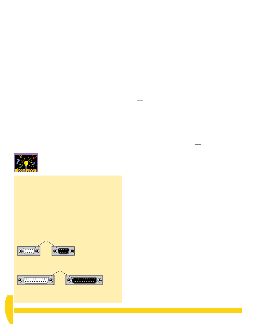
The connectors on the communications cable
supplied with your DT800 are of the “DE” female
type. This is a 9-pin D-shaped connector, as shown
below.
Another common comms connector is the “DB”
type, which is also D-shaped but has 25 pins. If
your computer’s COM port has one of these, you’ll
need to add a 9-pin to 25-pin adaptor to the end of
your DT800 comms cable.
Pin 1
DE-9 MaleDE-9 Female
Pin 1
DB-25 MaleDB-25 Female
FIGURE 5 Typical comms connectors
Characters
Things you type. The generic name for numbers (0, 1,
2, 3,…), letters (A, b, c, D,…) and symbols ($, %, &,
+,…).
UM-0071-A0
12 Getting Started with DT800
dataTaker
Page 13

CHAPTER 2
S
ET
U
P THE
H
ARDWARE
In this chapter, you get the DT800 hardware up-andrunning.
You firstly check that you have everything, then you
power the DT800 from the mains adaptor and connect
the computer to the DT800.
Mains adaptor
Comms cable
Cage-clamp tools
Potentiometer
Thermocouple
CD containing
software
and manuals
User’s manual
2-1
Make sure you have everything you’ll need to
successfully work through this user’s guide.
CHECKLIST
➲ Check that you have the following items:
a) From your DT800 shipping box:
• a DT800 data logger
• a mains adaptor
• a communications cable (“comms cable”; DE-9
female to DE-9 female) to connect between the
DT800 and the host computer
• a pair of cage-clamp tools to open the terminal
cage clamps for sensor wiring
• a potentiometer (variable resistance) mounted in
a child’s building block
• a thermocouple
• a DT800 CD (contains software and manuals)
•a
DT800 dataTaker User’s Manual
• the document you’re reading now (
Started with DT800 dataTaker
If anything is missing, contact your supplier
immediately.
b) You also need a PC running Windows 95, 98,
2000 or NT with
• a CD-ROM drive
• a 200MHz Pentium
• at least
•64MB of RAM (“memory”) for Windows 95
or 98
•128MB of RAM for Windows 2000 or NT
(NT also requires Service Pack 4 or later)
• 40MB of free space on the hard disk for
installing
(installed DeLogger occupies 25MB).
dataTaker
®
II processor or better
’s DeLogger software
Getting
)
FIGURE 7 Accessories supplied with your DT800 (plus
the user’s guide you’re reading now)
CHAPTER 2SET UP THE HARDWARE: Checklist 13
UM-0071-A0
Page 14
2-2
POWER THE
2-3
MAKE THE
DT800
There are several ways of providing power to your
DT800, which are covered in “Powering the DT800”
in Part C of the
particular, be sure to read “Main Battery is
Disconnected for Shipping”.
For this tutorial, you’ll simply use the mains adaptor.
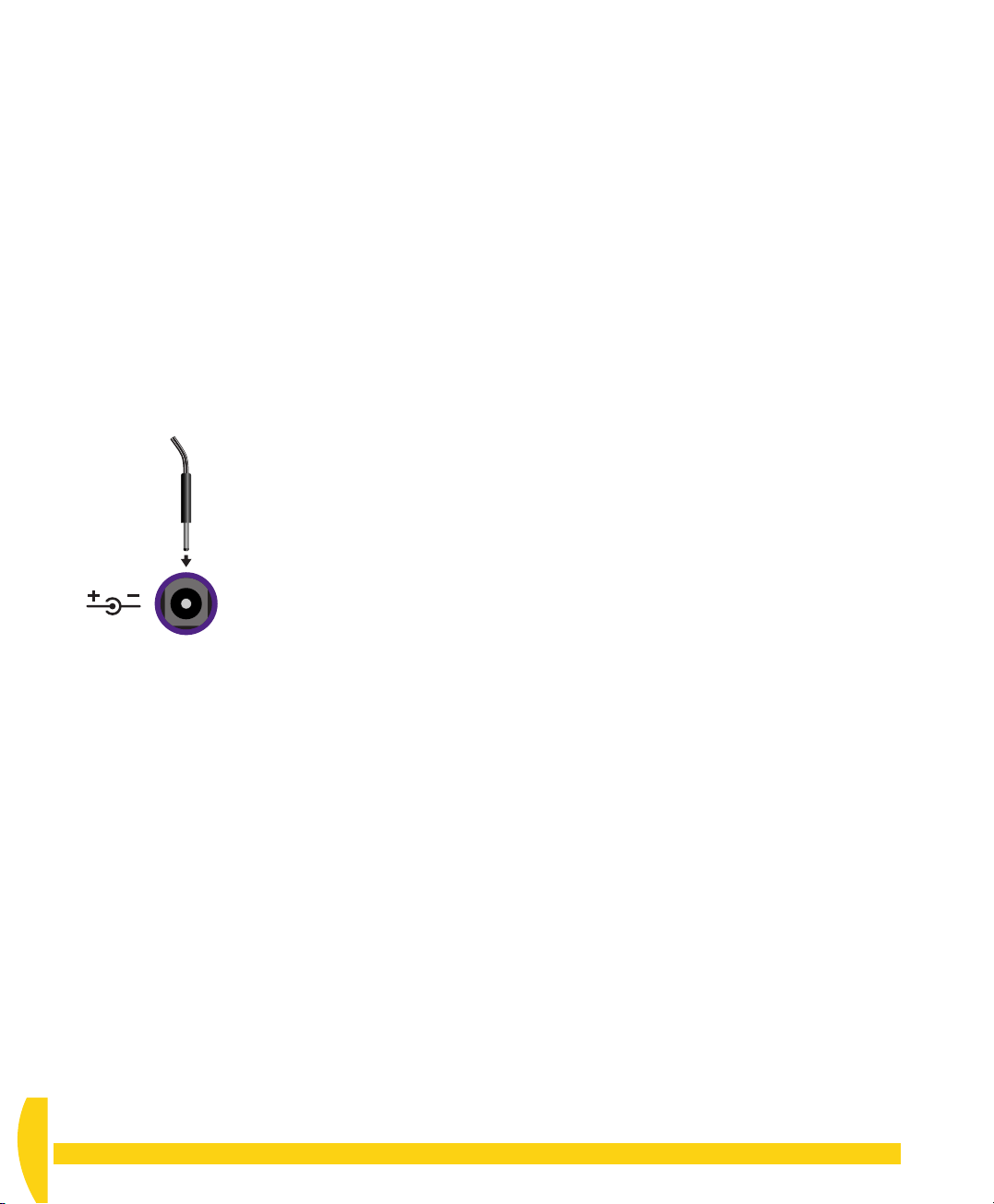
➲ Provide external power to the DT800 using
the mains adaptor supplied.
To do this…
a) Plug the coaxial connector of the mains adaptor into
the coaxial
DT800.
FIGURE 8 Powering the DT800 from a mains
adaptor
DT800 dataTaker User’s Manual
11–28Vdc
11–28Vdc
socket on the left side of the
. In
HARDWARE
CONNECTION
For the computer to talk to the DT800, and the DT800
to return data to the computer, you must establish a
communications link between the two.
You can use any of the links described in the Extras
panel “Communications Links”, but in this guide we’ll
use the simplest of all, the comms cable supplied with
the DT800. You’ll connect it between the DT800’s Host
RS-232 port and a COM port on your computer.
➲ Locate and identify your computer’s COM1
serial port then connect the comms cable to it.
To do this…
a) On the rear of your computer, locate the COM1
port and remove anything plugged into it (a
modem, for example).
If you find several likely connectors and don’t know
which is COM1, just choose any one. Later, if
communication with the DT800 is unsuccessful,
simply change to a different connector (we’ll remind
you about this in the next chapter).
b) Plug either end of the comms cable supplied with
the DT800 into the computer’s COM1 port.
b) Plug the mains adaptor into a wall outlet and, while
watching the DT800’s front panel, switch on at the
wall.
If the DT800’s internal main battery is not connected
(we’re assuming yours is not), the five red LED (lightemitting diode) indicators on the front panel flash
rapidly four times. Then the Acquiring LED begins its
“heartbeat” flash — every three seconds. (The
functions of these LEDs are described in “Indicator
LEDs” in Part B of the
Manual
UM-0071-A0
14 Getting Started with DT800
supplied with your DT800.)
DT800 dataTaker User’s
➲ Connect the comms cable to the DT800.
To do this…
a) On the left side panel of the DT800, plug the other
end of the comms cable into the connector labelled
Host RS-232
.
dataTaker
Page 15
2-4
ATTACH A SENSOR
Now use the potentiometer supplied with your DT800
(see Figure 7 on page 13) to simulate a resistive
sensor.
Firstly, you attach this “sensor” to your DT800.
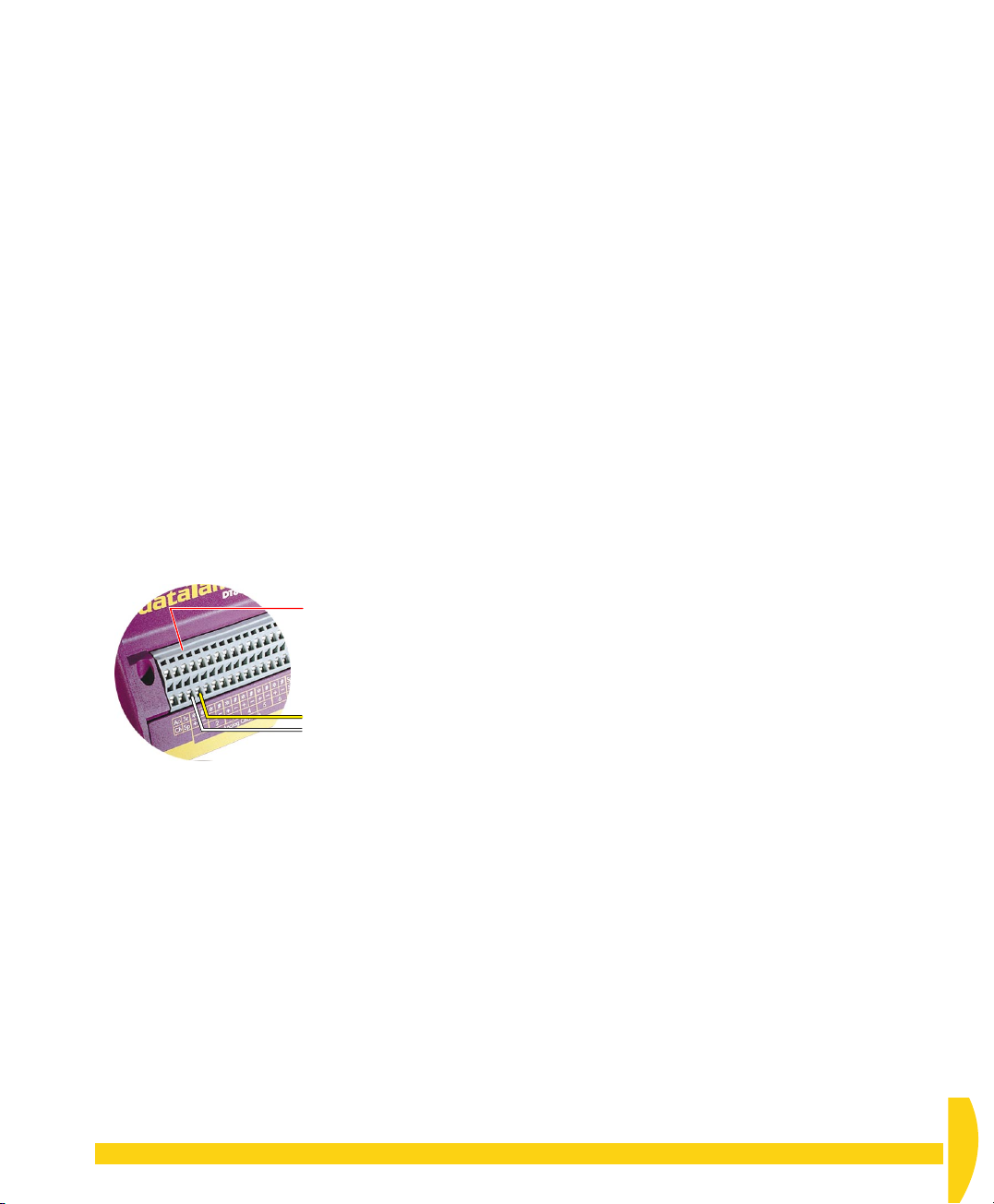
➲ Attach the potentiometer supplied to analog
channel 1 of your DT800 as shown in Figure 9.
To do this…
a) Locate the potentiometer (variable resistance)
supplied with your DT800.
It’s the child’s building block with a knob on top and
four wires.
b) Connect the potentiometer’s yellow and white wires
to the
+
and – terminals of analog channel 1 on the
front panel of the DT800, as shown in Figure 9.
To open the terminals, we recommend that you use
one of the cage-clamp tools supplied — refer to
“Connecting Sensors to Channel Terminals” in Part
B of the
DT800 dataTaker User’s Manual
.
Analog Channel 1
Yellow and white potentiometer
wires: one wire to the + terminal,
the other to the – terminal
(polarity is not important for this
type of “sensor”).
IGURE 9 Connecting the potentiometer
F
CHAPTER 2SET UP THE HARDWARE: Attach a Sensor 15
UM-0071-A0
Page 16

CHAPTER 3
S
ET
S
OFTWARE
U
P THE
DEL
OGGER
Host Software
You communicate with, supervise, and transfer data
from a DT800 by sending commands to it from the
host computer using host software.
DeLogger
application designed to make this communication,
supervision and data return as simple yet fully-featured
as possible.
As you work through this chapter, you’ll become
familiar with DeLogger and some basic DT800
operations.
host software is a powerful Windows
DT800 Host Software
Although you can use any terminal software to
communicate with your logger, you’ll find that
DT800-friendly software packages incorporate
productivity features specific to data acquisition,
data logging and the DT800 that make it pointless
to use anything else.
•
DeLogger
guide) has a totally graphical interface, which
means that knowledge of the
programming language is not required. Instead,
you supervise the DT800 just by clicking on icons
and making selections from menus and dialog
boxes. And, in addition to standard text output,
you can display and print real-time and logged
data in dynamic table, chart and mimic (needle
meter) views, load data into a fully-featured
(used predominately throughout this
dataTaker
3-1
INSTALL DELOGGER
Follow the steps in this section to install DeLogger from
the CD supplied with your DT800 to your computer’s
hard disk. The process requires about 40MB of free
space on the hard disk (installed DeLogger occupies
25MB) and takes less than five minutes.
If you already have DeLogger or DeLogger Pro
installed on your computer, see the Extras panel
“Re-Installing and Project Compatibility”.
DeLogger Serial Number
DeLogger is free to use and requires no serial number.
(But you do need one for DeLogger Pro — see the
“Enabling DeLogger Pro” Extras panel on page 18.)
spreadsheet, and replay saved data to any of the
dynamic views.
•
DeLogger Pro
the added features of modem support, a database
data storage option, the ability to connect to more
than one data site at a time, enhanced mimic
screens, and additional spreadsheet/graphical
analysis tools.
•
DeTransfer
your DT800) is the easiest non-graphical host
software to use with the DT800 programming
language. It provides complete access to all of the
DT800’s capabilities, and has separate send and
receive windows, which are the basis of its
exceptional and unique functionality. If you prefer
command-line interfaces, DeTransfer is for you.
is the big brother of DeLogger. It has
(included on the CD provided with
UM-0071-A0
16 Getting Started with DT800
dataTaker
Page 17
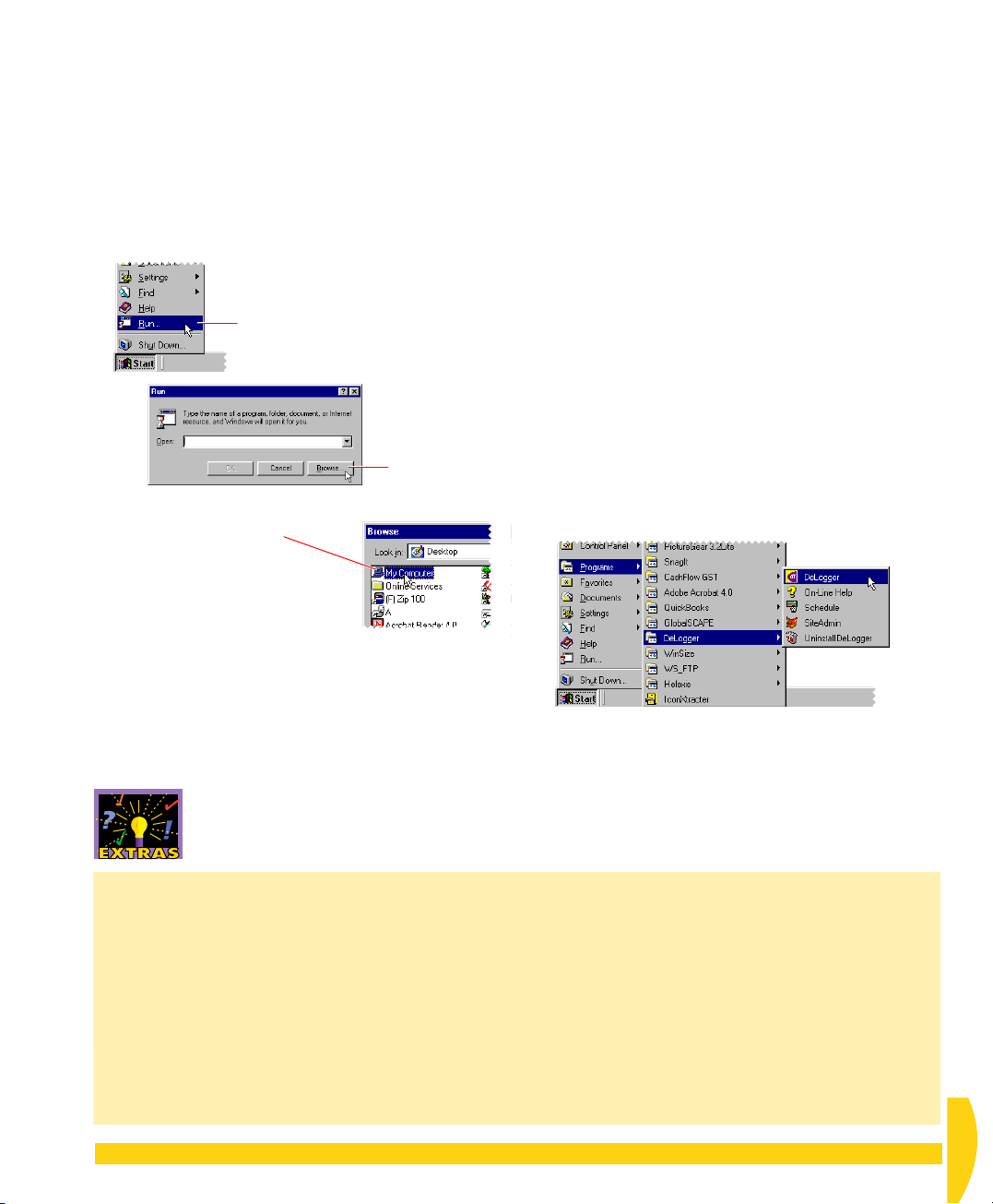
➲ Run the DeLogger installer Setup.exe,
FIGURE 11 Typical Programs menu after installation
which is located in the DeLogger folder on the
CD supplied (
You do not need a serial number for this
installation of DeLogger.
To do this…
a) Place the CD supplied with your DT800 into your
computer’s CD drive.
b) Follow the numbered steps in Figure 10
Double-click in order:
➌
My Computer,
dataTaker (the current CD),
the Software folder,
the DeLogger folder,
and finally
Setup or Setup.exe (may
appear in uppercase).
IGURE 10 Starting the DeLogger installer
F
Software
> DeLogger > Setup.exe
On the Windows taskbar, click the
➊
Start button and select Run….
.
Click the
➋
Browse…
button.
c) In the Run dialog box, click
OK
.
The DeLogger installer starts.
).
d) Follow the on-screen instructions.
e) After clicking
box, restart the computer (
Shut Down…
Finish
in the Setup Complete dialog
Start
menu >
> select
Restart
> OK).
f) When the computer has restarted, notice that the
Start
>
Programs
folder
(Figure 11), from which you can launch
•
DeLogger
• On-Line Help
•
Schedule
menu now contains a
— the main application
— for DeLogger Pro users; a utility that
automatically runs DeLogger Pro events at predetermined times (for example, dial a data site
at 6:00pm every day, unload data on the
second Tuesday of every month, or run Job3
every 15 minutes between 11am and 3pm
every Friday)
•
SiteAdmin
— a utility that allows you to clear
DeLogger’s error and alarm logs
•
Uninstall DeLogger
— use to remove DeLogger
from the hard disk.
DeLogger
You are returned to the Run dialog box, which now
contains the path to DeLogger’s Setup.exe.
Re-Installing and Project Compatibility
Earlier Versions
pre-version 4) of DeLogger already exists on the
computer, you can do one of the following:
•
Clean Install
Windows’ Add/Remove Programs control panel)
then install the new version.
•
Have Both
directory from the old one (both version 3 and
version 4 can co-exist on your computer, but not
in the same location).
CHAPTER 3SET UP THE DELOGGER SOFTWARE: Install DeLogger 17
If an earlier version (that is,
Remove the existing version (use
Install the new version to a different
Project Compatibility
Project files from earlier
versions (that is, pre-version 4) of DeLogger or
DeLogger Pro can not be used with this version
(version 4) of DeLogger (or DeLogger Pro). You’ll
need to re-create your version 3 projects using the
new version of DeLogger.
DeLogger and DeLogger Pro Together
Do
not install DeLogger 4 and DeLogger Pro 4 together
on a computer.
UM-0071-A0
Page 18
3-2
START DELOGGER
➲ Start your new installation of DeLogger for
the first time.
To do this…
a) On the
click
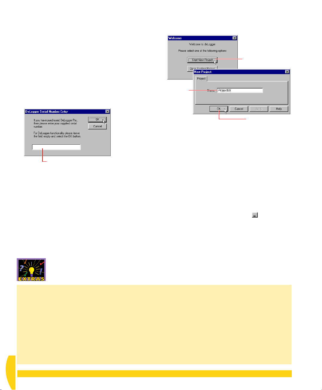
DeLogger starts and presents you with its Serial
Number Entry dialog box (Figure 12).
b) In the Serial Number Entry dialog box, leave the
field empty and click
FIGURE 12 No serial number for DeLogger
The Welcome dialog box opens.
For more information about serial numbers and
upgrading see the “Enabling DeLogger Pro” Extras
panel.
c) In the Welcome dialog box, click
(Figure 13).
Start
menu>
DeLogger
Leave the field empty (unless you’re upgrading
to DeLogger Pro and have purchased a Pro
serial number) and click OK.
Programs
>
— see Figure 11.
OK
.
DeLogger
Start New Project
menu,
d) In the New Project dialog box that opens, type
Project99
(or whatever you like) and click OK
(Figure 13).
Click.
Type a
name
for your
new
project.
Then click OK.
FIGURE 13 Creating a new DeLogger project
Project99’s windows open within DeLogger’s main
window. Your screen should look like Figure 18
(page 25).
e) Notice that two windows are open in DeLogger’s
workspace (labelled
Prog1.dlp
and
Prog1.dl8
their title bars) and five windows are minimized at
the bottom of the workspace (
Form1.dlf, Text1.dlt, Chart1.dlc
Prog1.dlp
series
f) Click
is the program builder for DT500/600
dataTaker
Prog1.dlp
s, and
’s minimize button ( in its title
bar).
Mimic1.dlm
and
Prog1.dl8
is for your DT800.
You’re not using the DT500/600 program builder
in this tutorial.
in
,
Spread1.dls
).
Enabling DeLogger Pro
If you purchase DeLogger Pro, or purchase an
upgrade from DeLogger to DeLogger Pro, you’ll
receive a serial number that you use as follows:
•
If you’ve purchased DeLogger Pro
Install and
start DeLogger exactly as described in topics 3-1
and 3-2 beginning on page 16 but, when the
Serial Number Entry dialog box opens
(Figure 12), enter your DeLogger Pro serial
number.
UM-0071-A0
18 Getting Started with DT800
•
If you’ve purchased an upgrade from DeLogger to
DeLogger Pro
Register Product…
With DeLogger running, choose
from DeLogger’s File menu. In
the dialog box that opens (Figure 12), replace
0000-0000 in the field with your Pro serial
number and click
OK
. (0000-0000 is the default
serial number that enables basic DeLogger.) The
next dialog box offers you the choice of quitting
then restarting the program with the new
functionality either now or later.
dataTaker
Page 19

g) In DeLogger’s File menu, choose
This saves the change you just made to the window
view (minimizing Prog1.dlp).
We’ll introduce you to the things you can see in the
DeLogger window in the next chapter. For now,
continue with “Make the Software Connection”.
Save Project
.
3-3
MAKE THE SOFTWARE CONNECTION
Your computer is physically connected to the DT800
(you did this in the previous chapter). Now you
complete the communications link by making the
software connection
From now on in this guide we use the term
“C
onnection” — note the uppercase C — to mean
“software connection” (see also page 28).
The “dt800 Com1” Connection
Although you can create your own Connections, in this
tutorial you’ll use one already provided with DeLogger.
It’s called
DeLogger
• that the
• to detect the DT800’s communications baud rate
• to use software flow control when communicating
In addition, this Connection specifies that the DT800 is
directly connected to the computer’s COM1 serial port.
So, if you chose to plug the comms cable into a serial
port other than COM1
modify the dt800 Com1
(
Connections
dt800 Com1
dataTaker
communications link is a
and match the computer’s baud rate to it
with the DT800 (see the “Flow Control” Extras
panel).
between DeLogger and the DT800.
and contains instructions that tell
at the other end of the
DT800
on the back of your computer,
Connection in DeLogger now
menu >
Properties…
).
Connection Troubleshooting
If DeLogger responds with an “Error connecting
to…” message, try the following:
• Check that the comms cable’s connectors are
firmly plugged into their sockets, then repeat
“Make the Software Connection” above.
• If the computer has more than one COM port,
swap the comms cable to the other port, then
repeat “Make the Software Connection” above.
• Perform a hardware reset on the DT800
(described in “Resetting the DT800” in Part H of
the
DT800 dataTaker User’s Manual
“Make the Software Connection” above.
• Make sure there is no software configured to
CHAPTER 3SET UP THE DELOGGER SOFTWARE: Make the Software Connection 19
), then repeat
access the computer’s COM port you’re using for
the DT800 (COM1 if you’re following this tutorial
“to the letter”). If there is such software, you can
• re-configure it to use a different COM port, or
• quit it while you use DeLogger (you’ll have to
do this every time), or
• remove it (use Windows’ Add/Remove
Programs control panel).
Then repeat “Make the Software Connection” above.
• Change the serial port specification in the
DeLogger software Connection (
>
Properties
the Software Connection” above.
) to, say, COM2. Then repeat “Make
Connections
menu
UM-0071-A0
Page 20
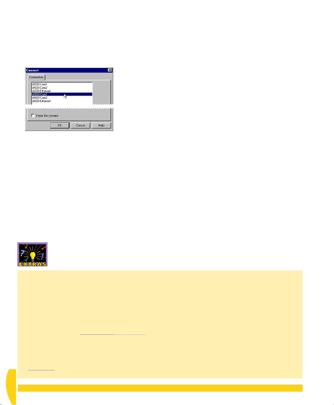
➲ Connect to the DT800 using dt800 Com1.
To do this…
a) In DeLogger’s Connections menu (fourth from the
left), choose
b) In the Connect dialog box that opens, highlight (one
click)
Connect…
dt800 Com1
.
and click OK.
3-4
VERIFY THE CONNECTION
Now carry out some simple communication with the
DT800.
FIGURE 14 Connect dialog box
Two progress bar dialog boxes open, then close
automatically to indicate that you’ve successfully
connected to the DT800.
If a dialog box opens asking if you want to upgrade
to a later version of the
No
. (You can do this at another time.)
If DeLogger is unable to connect (you’ll see an
“Error connecting to…” message), go to the Extras
panel “Connection Troubleshooting”.
dataTaker
firmware, click
➲ Get the
To do this…
a) From DeLogger’s
left), choose
DeLogger communicates with the DT800, retrieves
information about what’s currently happening in the
DT800, and presents the information to you in the
large dialog box that opens (Figure 15).
You can do this anytime you’re connected to a
DT800. In fact, as well as using this command to
find out which schedules (see page 33) and alarms
(see page 63) are currently running in the DT800,
how much data storage (memory) is used and free
in the DT800 and so on, you can send this
command simply to confirm that you’re connected
to the DT800.
b) Look through the Status dialog box tabs to
familiarize yourself with the information you can get
from it, then click
dataTaker
dataTaker
Status…
OK
’s status.
menu (sixth from the
.
.
Flow Control
Flow control is a communications feature that allows
communicating devices to control each other’s
transmission of information.
DeLogger and the DT800 support two types of flow
control:
•
Hardware Flow Control (HWFC)
signals are sent between the communicating
devices by means of R
the cable.
•
Software Flow Control (SWFC)
commands XOFF and XON are sent between the
communicating devices by means of the
data
wires in the cable.
UM-0071-A0
20 Getting Started with DT800
TS and CTS control wires in
Flow control
Flow control
Setting Flow Control
type of flow control at each end of a
communications link. For example, for this tutorial,
both the DT800 and your DeLogger Connection
must be set for software flow control.
This Tutorial
software
default/factory setting for a new DT800 and for
DeLogger’s
a DT800 that has previously been set to hardware
flow control, you must either change the DeLogger
Connection to hardware flow control also, or change
the DT800 to software flow control.)
flow control for this tutorial. This is the
We recommend that you use
dt800 Com1
You must set the same
Connection. (If you’re using
dataTaker
Page 21
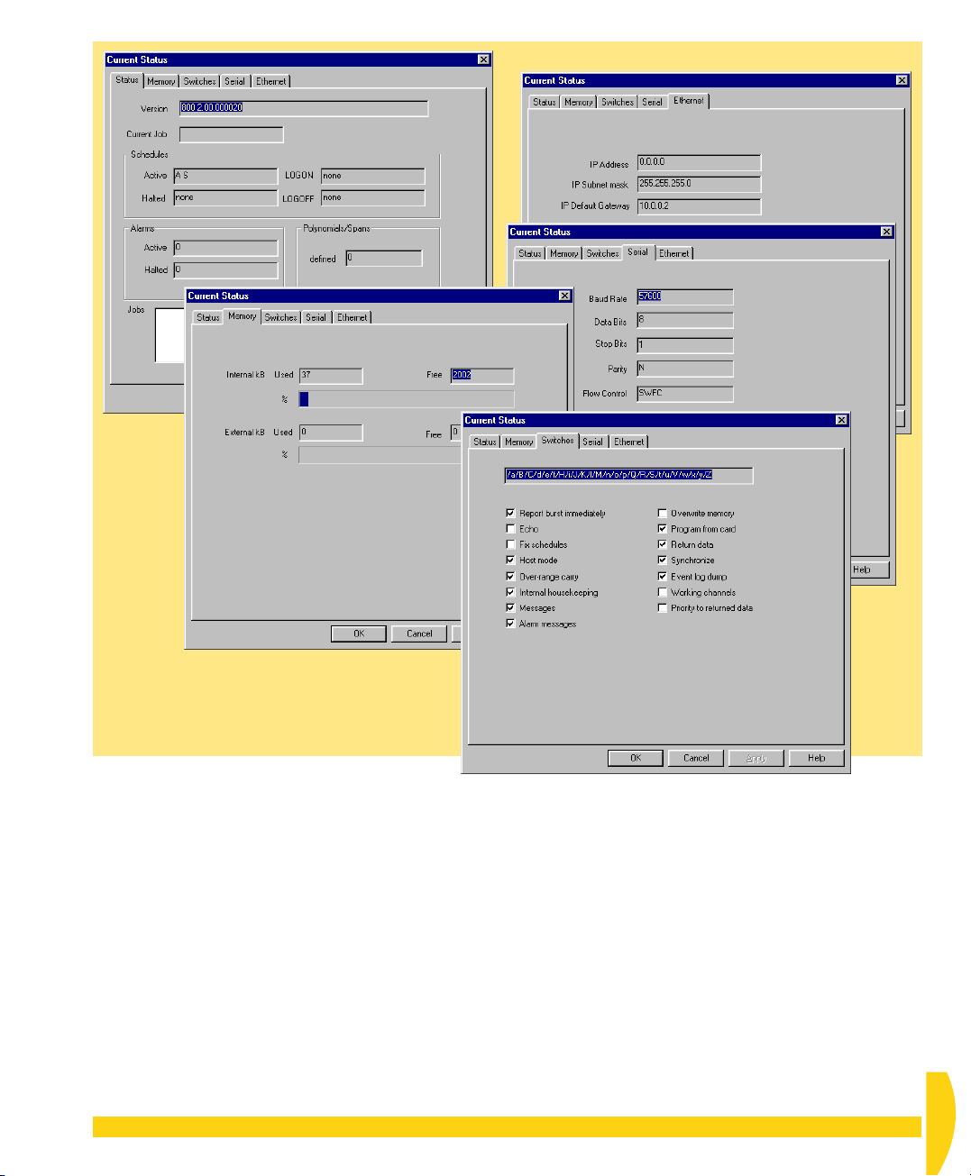
FIGURE 15 The five tabs of DeLogger’s DT800 Status dialog box
CHAPTER 3SET UP THE DELOGGER SOFTWARE: Verify the Connection 21
UM-0071-A0
Page 22

CHAPTER 4
A Q
DEL
DeLogger host software provides you with a powerful
set of tools for working with your DT800, which are
fully covered in
with dataTaker
To get you up-and-running quickly now, this chapter
presents a bird’s-eye-view of DeLogger’s windows,
main toolbar and menus, which you’ll use in later
chapters.
Be sure not to miss “More Important Concepts and
Terminology” on page 28.
UICK
O
VERVIEW OF
OGGER
Using DeLogger and DeLogger Pro
.
4-1
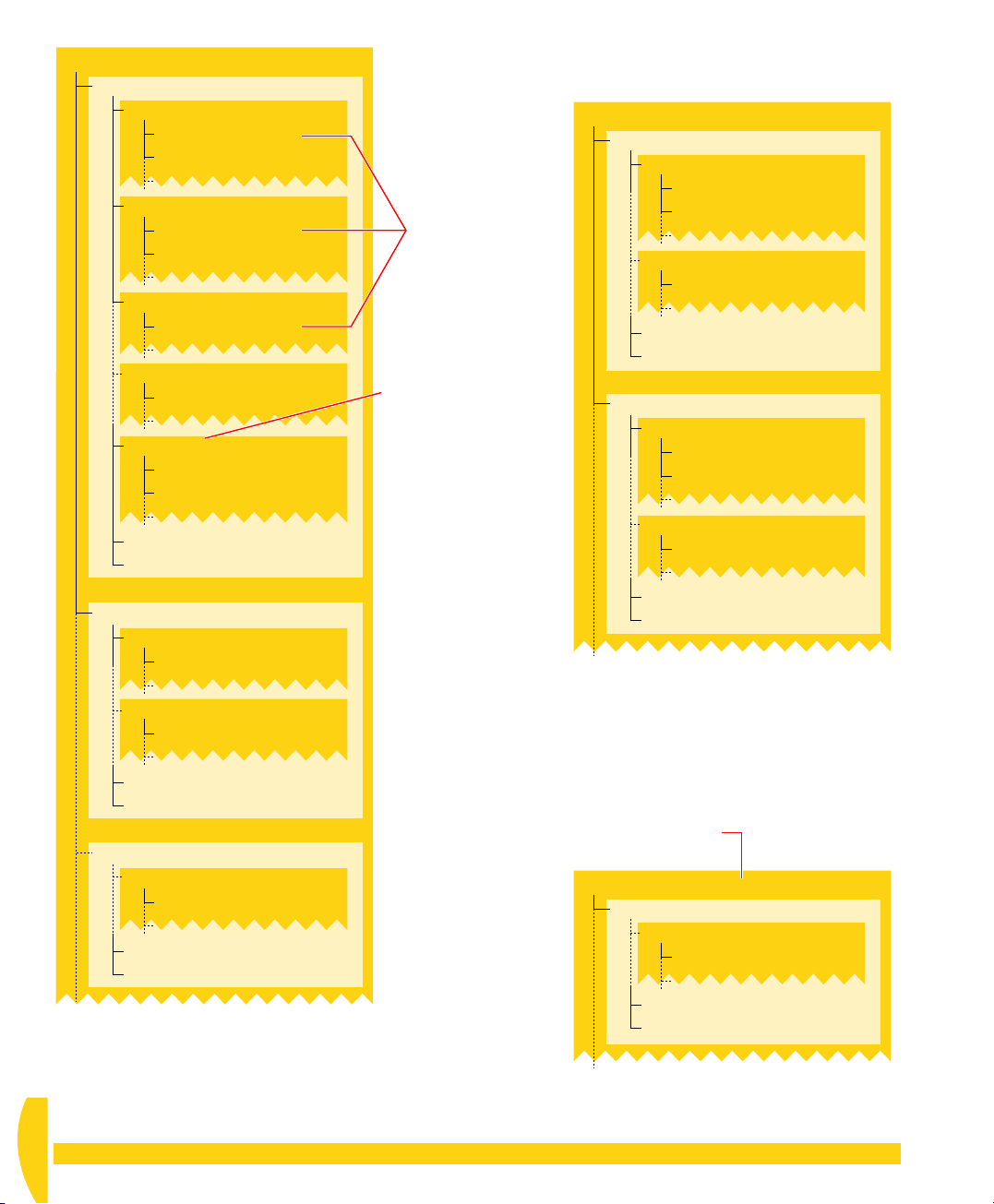
Figure 16 is an overview of the window types
available in a DeLogger project and some of the things
you can do with them. Figure 17 shows the
relationship between DeLogger projects, programs,
schedules and channels. Figure 18 shows how
DeLogger starts up the first time after installing it.
Then the remainder of this chapter gives you a quick
visual tour of DeLogger:
• DeLogger’s main toolbar — page 26
• DeLogger menus — page 27
• important DeLogger concepts — page 28
THE BIG PICTURES
UM-0071-A0
22 Getting Started with DT800
dataTaker
Page 23

Program builder window — create
a program and send it to the DT800.
(Note: this is different from the
program builder used for the DT50
and the DT500/600 Series.)
Form window — view each channel’s
latest data and other information,
one row per channel.
Chart window — view live trend plots
(data versus time) like traces on a chart
recorder.
REAL-TIME
CONNECTION
REPLAY
CONNECTION
REAL-TIME
CONNECTION
REPLAY
CONNECTION
Note
You can open
more than one of each of
these window types in any
DeLogger project (choose
New from the File menu).
Send program to DT800
Dynamic data views —
these DeLogger windows
display incoming real-time
or replay data “live”.
Print
Print
Text window — view incoming data in
the
display screen
send to the DT800 in the
; type commands to
entry screen
(an alternative to the program builder if
you’re familiar with the DT800 native
programming language).
Load text file (.cmd/.dxc or .txt)
Load program builder as text
Mimic window — view data on a
needle meter; add background
graphics.
Spreadsheet window — load a
replay file one row per timestamp, one
column per channel. Then manipulate
the data, save it in a variety of formats,
or export it directly into Microsoft Excel.
Load session from replay file
Capture data to disk as it arrives
REAL-TIME
CONNECTION
REPLAY
CONNECTION
(as a replay file .dlr)
Save screen buffer (.txt or .csv)
Print
Save text file (.cmd/.dxc or .txt)
Send program to DT800
Print
REAL-TIME
CONNECTION
REPLAY
CONNECTION
Print
Static data view — load
an entire replay file into
DeLoggger’s spreadsheet
window.
Load into Excel (opens Excel)
Export worksheet
Print
FIGURE 16 The big picture 1 — an overview of the window types available in a DeLogger project
CHAPTER 4 A QUICK OVERVIEW OF DELOGGER: The Big Pictures 23
UM-0071-A0
Page 24
PROJECT A
Program Builder 1 (Program 1)
Schedule A
Schedule B
Schedule C
Schedule …
Schedule K
Other commands
Comments
Program Builder 2 (Program 2)
Schedule …
(every 5 seconds)
Channel 1 (details…)
Channel 2 (details…)
(every hour)
Channel 1 (details…)
Channel 3 (details…)
(every day)
Channel 1 (details…)
(…)
Channel … (details…)
(…)
Channel … (details…)
Channel … (details…)
Channel … (details…)
A channel can be
scanned by more
than one schedule.
A program can contain
up to eleven schedules
(“timetables”, “agendas”).
They are labelled A, B,
C, D,…K.
PROJECT B
Program Builder … (Program …)
Schedule …
Schedule …
Other commands
Comments
Program Builder … (Program …)
Schedule …
Schedule …
Other commands
Comments
(…)
Channel … (details…)
Channel … (details…)
(…)
Channel … (details…)
(…)
Channel … (details…)
Channel … (details…)
(…)
Channel … (details…)
Schedule …
Channel … (details…)
Other commands
Comments
Program Builder … (Program …)
Schedule …
Channel … (details…)
Other commands
Comments
FIGURE 17 The big picture 2 — Projects, programs, schedules and channels
UM-0071-A0
24 Getting Started with DT800
project > program (job) > schedule > channel
DeLogger’s conceptual hierarchy:
PROJECT …
Program Builder … (Program …)
Schedule …
Channel … (details…)
Other commands
Comments
(…)
dataTaker
Page 25
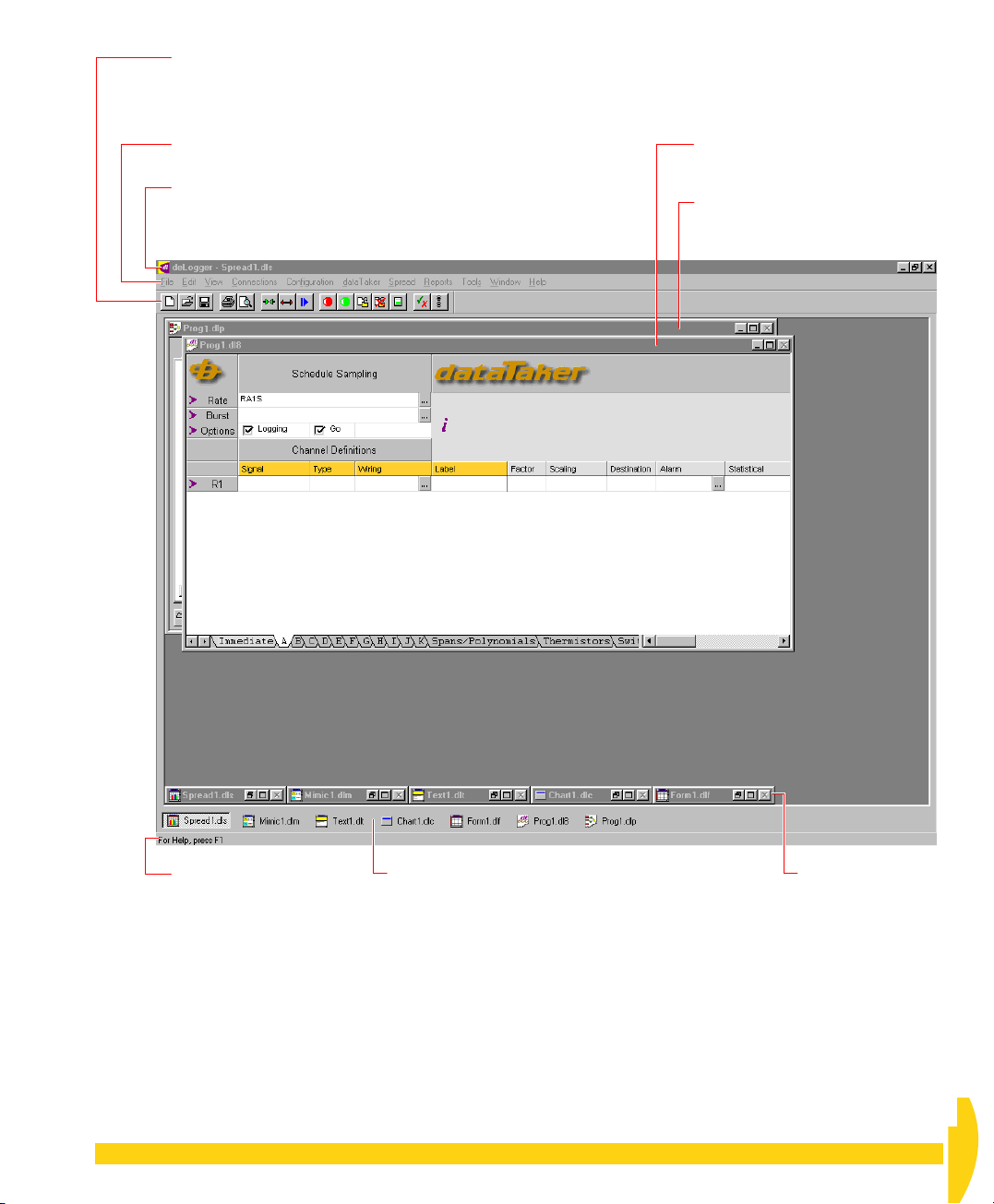
DeLogger’s main toolbar allows you to quickly initiate frequently-used file,
connection and
dataTaker
commands. See
Figure 19.
The buttons duplicate commands found on the menu bar. If you drag the
toolbar (by its gray background) from its docked position it becomes a
floating toolbar. Use the View menu to show or hide the main toolbar.
Menu bar
See
Figure 20.
The title bar contains standard
Windows controls (minimize,
maximize,…) and the name of the
front-most DeLogger window.
DT800 program builder window.
Here you create a program ready to
send to the DT800. See
page 31.
DT500 series program builder
window — for DT50 and DT500/600
Series
Watch the status bar for
prompts when you pause
the mouse over a button or
a menu item.
Use the View menu to show
or hide the status bar.
The document bar gives you quick access to DeLogger’s
windows:
• Single-clicking a window’s name in the document bar
brings that window to the front in its current view state
(minimized, maximized, or in-between). It’s like
choosing a window using the Window menu, only
Minimized DeLogger
windows (form, chart,
text, mimic and
spreadsheet)
faster.
• Double-clicking a window’s name in the document bar
brings the window to the front and maximizes it.
• Once any window is maximized, a single click on a
filename in the document bar maximizes that file (and
minimizes the previous one).
Use the View menu to show or hide the document bar.
FIGURE 18 The big picture 3 — DeLogger’s startup layout after a new installation
CHAPTER 4 A QUICK OVERVIEW OF DELOGGER: The Big Pictures 25
UM-0071-A0
Page 26
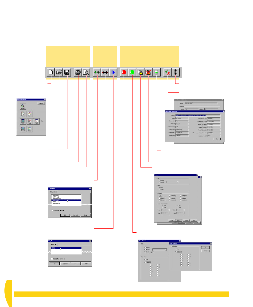
4-2
DELOGGER’S MAIN TOOLBAR
The buttons on DeLogger’s main toolbar duplicate
frequently-used commands from the
and
dataTaker
Create a New
(the New Document
dialog box opens).
Open another
Save the current
Open a full-page Print Preview
menus.
File
menu
commands
document
project.
project.
Print the current window
of the current window.
File, Connections
Connections
menu
commands
If
Toolbar
is ticked on the View menu, the main toolbar
is always visible no matter which DeLogger window
you’re working in.
dataTaker
menu
(DeLogger must be connected
commands
to the DT800)
Send the STATUS command
to the DT800.
Send the TEST command
to the DT800.
TEST resultsTEST results
Open the Memory Card Options
dialog box.
Quit (stop) the unload process.
Start the Unload process (the first Unload
dialog box opens).
STATUS resultsSTATUS results
Connect to the DT800 (the
Connection dialog box opens).
Disconnect from the DT800.
Play a replay file (the
Replay Connection
dialog box opens).
IGURE 19 DeLogger’s main toolbar
F
UM-0071-A0
26 Getting Started with DT800
Run (Go) the current schedule in the DT800.
Halt the current schedule in the DT800.
Halt Options
Halt Options
dialog box
dialog box
Run Options
Run Options
dialog box
dialog box
dataTaker
Page 27
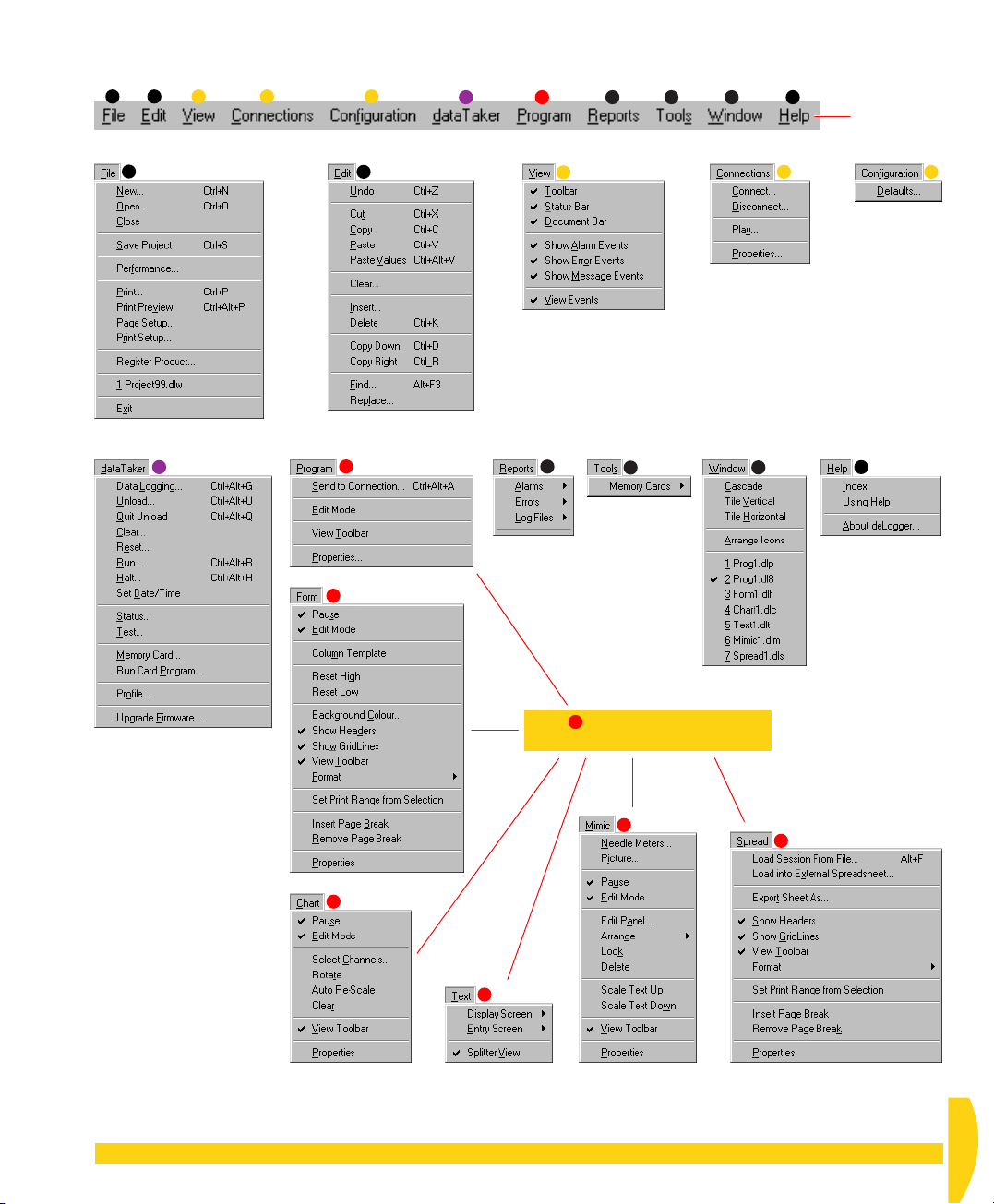
4-3
DELOGGER’S MENUS
11223
6
4
5
6
7
8
9
10
11
Menu bar
3
7
7
8
9
4
10
11
5
7
Menu changes according to which
DeLogger window is front-most.
7
F
IGURE 20 DeLogger’s menus (sub-menus not shown)
7
7
7
CHAPTER 4 A QUICK OVERVIEW OF DELOGGER: DeLogger’s Menus 27
UM-0071-A0
Page 28

4-4
MORE IMPORTANT CONCEPTS AND TERMINOLOGY
Connection
A DeLogger
of communications settings: a user-defined and usernamed software tool that automates the process of
linking DeLogger to a
It specifies
• a particular computer port, a particular data site
and particular communications parameters — for a
serial
• an IP address and port number — for a TCP or UDP
Ethernet
• a particular DeLogger replay file (*.dlr; see
page 30) — for a
External
data
sites
Connection
Connection
network
External
physical
comms
links
Serial comms cable
Serial comms cable
Ethernet network
is nothing more than a group
data site
(explained below).
Connection
file
Connection.
Example
DeLogger
Connections
dt800 Com1
DT800 SERIAL2 9600
DT800 ETHERNET
DeLogger
DeLogger
display
and
capture
engine
DeLogger’s live Connect dialog box or Replay dialog
box and click
To connect to an
external data site
(a
serial
Connection):
FIGURE 22 Making a Connection
or
network
OK
(Figure 22).
Choose from the
Connections
In the dialog box
that opens, select a
Connection.
DeLogger makes
the Connection.
menu
or click
To connect to an
internal data site
(a
replay
file
Connection):
Data Site
A source of data. DeLogger data sites can be
• external — a DT800 (or, to be more precise, the
Connection to
• internal — a replay file (or, to be more precise, the
Connection to
a DT800)
a replay file).
(internal data site)
Replay file
FIGURE 21 DeLogger’s Connection concept
MY FILE
A Connection is the link between a data site and
DeLogger.
You can create any number of Connections, each for a
specific use, but DeLogger can have only one active
Connection at a time — see the Extras panel “How
Many Connections?”.
DeLogger automatically saves each Connection, ready
for the next time you want to use it.
To link DeLogger to a particular data site, you simply
select the appropriate Connection name from
UM-0071-A0
28 Getting Started with DT800
How Many Connections?
With DeLogger, you can make only one
Connection at a time. (DeLogger automatically
disconnects from the current data site in order to
connect to another one.)
But with DeLogger Pro
to many data sites at the same time.
, you can make Connections
dataTaker
Page 29
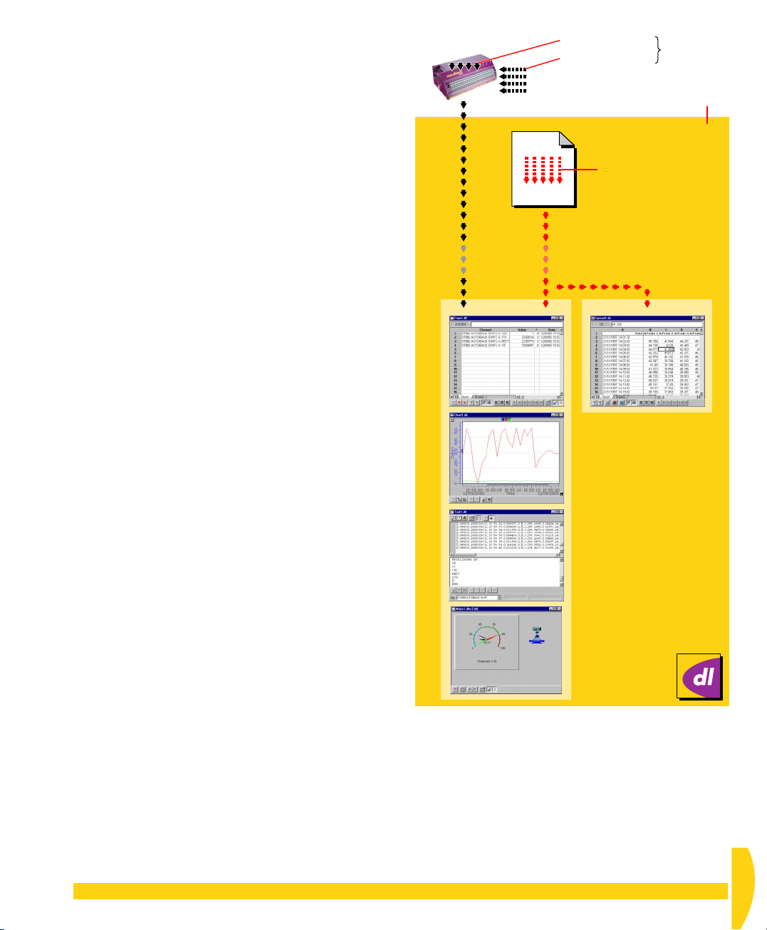
Channel
A “conduit” or “route” for data. See Figure 23.
DT800 Channels
The DT800 has
•
external physical channels
on the outside to which you connect sensors and
transducers, and
•
internal physical channels
information, such as time and date from the
DT800’s clock/calendar, temperature, battery
voltage, system variables and system timers.
— the sets of terminals
— internal sources of
Internal channels
External channels
SENSORS
HISTORICAL CHANNELS
Replay file
PHYSICAL
CHANNELS
DeLogger
DeLogger Channels
DeLogger works with
•
physical channels
— data returned from a DT800 (a
“physical data site”) either in real time, or unloaded
at the end of a logging session
•
historical channels
— data supplied from a replay
file (a “replay data site”; see page 30).
Figure 17 (page 24) shows where channels fit within
projects, programs and schedules.
Details of all channels are kept in DeLogger’s
(see page 30).
hub
data
Programs and Jobs
When you’re working with DeLogger and a DT800,
the terms
program
and
job
mean the same thing.
Because the DT800 works with program entities called
“jobs”, every program you create in DeLogger is
automatically tagged as a “job” when you send it to a
DT800.
This tagging is almost invisible to the user (you can see
it if you
Load DLP (Program) Text
into a text window
entry screen). It’s necessary for the DT800 to recognise
a DeLogger program, but not for DT50 or DT500/600
Series
dataTaker
s.
Database
DeLogger stores housekeeping information (such as
Connections, windows, and window sizes and
positions) in a database.
And, by upgrading to DeLogger Pro, you can have
extra database data management capabilities that
add immense power to your data collection, analysis,
presentation and reporting — all without leaving
DeLogger Pro.
Physical
channel
data
Form window Spreadsheet window
Form window Spreadsheet window
Chart window
Chart window
Text window
Text window
Mimic window
Mimic window
FIGURE 23 Channel concepts — external and internal,
Historical
channel
data
physical and historical
CHAPTER 4 A QUICK OVERVIEW OF DELOGGER: More Important Concepts and Terminology 29
UM-0071-A0
Page 30
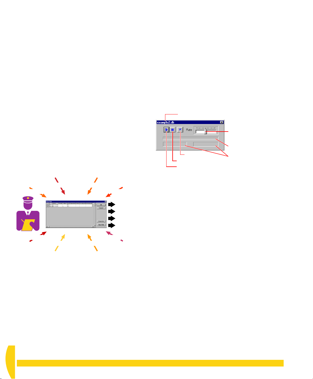
Data Hub
An indispensable table in DeLogger’s database that
stores details of every channel known to DeLogger
during the current Connection (Figure 24).
Think of the data hub as a “resource controller” whose
function is to
• monitor which channels are available
(it does this — from all the data sites you’re currently
connected to; see the Extras panel “How Many
Connections?” — every time you save a program
builder window, send a program to the DT800, or
otherwise communicate with a data site)
• keep an up-to-date list of available channels and
their details
• compare available data site channels against those
you’ve assigned in the current project’s windows
and warn you of any mismatch — that is, if any
channels defined in DeLogger’s windows aren’t
currently available from the connected data site(s)
• make valid channels available for you to use in the
various DeLogger windows.
When you disconnect from a data site, that site’s
information is automatically cleared from the hub.
CHANNEL
DETAILS
CHANNEL
DETAILS
Data
site
Data
site
Data
site
CHANNEL
DETAILS
Makes valid
channels
available to
DeLogger
views
CHANNEL
DETAILS
Data
site
Data
site
Data
site
CHANNEL
DETAILS
CHANNEL
DETAILS
Data hubData hub
Data
site
CHANNEL
DETAILS
CHANNEL
DETAILS
Data
site
IGURE 24 Data hub — DeLogger: one Connection at
F
a time; DeLogger Pro: several Connections at a time
Logged Data
Data stored in the DT800’s internal memory or in an
inserted memory card.
You retrieve logged data using the
on DeLogger’s
dataTaker
menu.
Unload…
command
The DT800 can log data and return real-time data at
the same time.
Replay Data, Replay File
Replay data
, *.dlr) in a format that DeLogger can replay to its
file
form, chart, text and mimic windows, just as if the data
was arriving in real time (except that you can control
the speed of the replay; see Figure 25).
FIGURE 25 DeLogger’s replay control panel
You can save both
• real-time data and
• logged data unloaded from a DT800
as a replay file.
DeLogger can also replay existing
files (
A replay file is just another data site: to link to it, you
use a DeLogger Connection called a
Connection
Connection
You use the File tab in the
Properties
Connections. See Figure 22.
is data saved in a computer file (a
Name of the file to be replayed
Drag pointer to adjust
replay speed
Replay progress bar
Reset
Pause
Play
Date and time of the
record currently being
replayed
*.dx8
dataTaker
unload files).
replay file
(or a
file Connection
or a
replay
).
Connections
menu >
dialog box to create and edit replay file
and
replay
*.dxu
Real-Time Data
Data returned to the computer in real time — that is,
the moment it is obtained by the DT800.
Front-Most Window
The DeLogger window that is in front of any others on
your screen. Its title bar is more brightly colored than
all the others, and it’s always the last window you
clicked on. Sometimes known as the “current”, “toplevel”, “active” or “focus” window.
We don’t use the term “active window” because
DeLogger windows behind the front-most window can
still be active. For example, values in a background
form window can change as data arrives.
UM-0071-A0
30 Getting Started with DT800
dataTaker
Page 31
CHAPTER 5
Y
OUR
F
IRST
P
ROGRAM
When you installed DeLogger in Chapter 3 you
created and named a DeLogger project (done in “Start
DeLogger” beginning on page 18). We called it
Project99
DeLogger is running on the computer and connected to
your DT800. You verified this in “Verify the
Connection” (page 20). You also connected the
potentiometer to channel 1 of the DT800, to simulate a
resistive sensor (page 15).
Now, in this chapter, you’ll
• get to know DeLogger’s program builder window —
• create a program using a program builder window
• see the “raw” version of your program — page 36
• send the program to the DT800 — page 36.
.
page 31
— page 33
Analog Channels, Digital Channels —
What’s the Difference?
Analog channel
input values between a minimum and a maximum.
Digital channel
only two values:
•
on
or
•
high
or
•1 or
0
Often an analog channel is able to “read” a digital
input, but the reverse is not true.
— accepts a continuous range of
— expects an input that has one of
off
low
5-1
DELOGGER’S PROGRAM BUILDER WINDOW
A DT800
for creating a DT800 program. As Figures 26 and 27
show, you use it by choosing various schedule,
channel and other items from drop-down lists and
dialog boxes.
Important Program Builder Facts
• Each program builder window creates just ONE
• A project can contain more than one program
• A DT800 program is ever
• The DT800 can only run one program at a time.
program builder
DT800 program.
Although the program may contain several
schedules and involve many DT800 channels,
there is only one program per program builder
builder — that is, more than one program.
Figure 17 on page 24 illustrates this.
(To add another project builder window, choose
New
on the File menu, then click the
Program
program builder window — everything defined on
ever
builder.
When you send a new program, it replaces any
existing program in the DT800 (DeLogger first
ensures that this is what you want to do).
button.)
y tab across the bottom of the program
window is DeLogger’s tool
.
DT800
ything you specify in a
CHAPTER 5YOUR FIRST PROGRAM: DeLogger’s Program Builder Window 31
UM-0071-A0
Page 32
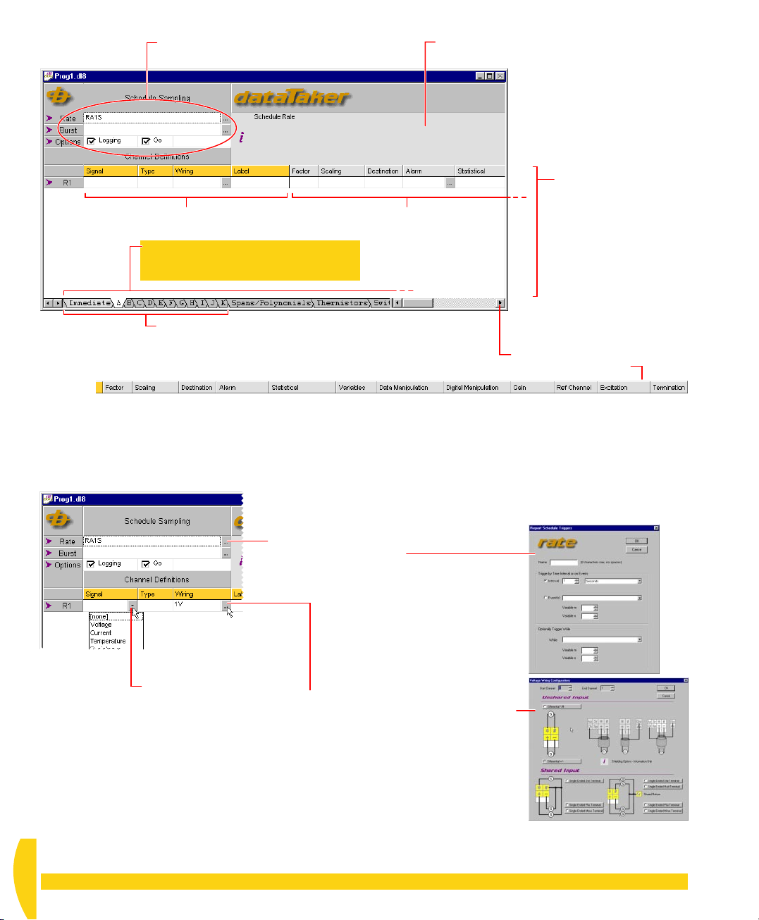
Specify the schedule’s
➋
primary details here.
Fixed columns Scrollable columns
A program builder’s program consists of
everything specified on all of these tabs
(scroll right to reveal more tabs).
Select a schedule here: Immediate (a once-only
➊
scan) or triggered (A, B, C,…K).
FIGURE 26 DeLogger’s DT800 program builder — general sequence of use
When you click in a cell in the program builder,
information about the clicked item appears here.
Specify the schedule’s
➌
channels here.
Repeat from step 1,
➍
but use a different
schedule tab, if you
want to include other
schedules in the
program (you do this
when you want the
DT800 to do things at
different times or
according to different
triggers).
Scroll right to reveal
more column headings.
Click this Configure button to
open the Rate dialog box.
Choose Voltage from
this drop-down list, then… click this Configure button to open the
FIGURE 27 Using specific parts of the DT800 program builder — more details in the following topics
UM-0071-A0
32 Getting Started with DT800
Voltage Wiring Configurations dialog box.
dataTaker
Page 33

5-2
CREATE A PROGRAM
Now you’ll use a DeLogger program builder window
to create a simple program ready to send to the
DT800. (You can also create a program in a DeLogger
text window if you’re familiar with the
programming language. But, in this tutorial, we’ll do it
the graphical way — by pointing and clicking in the
program builder.)
The general steps for working in a program builder
window are summarized by the numbered instructions
in Figure 26.
Schedules
Scan
schedules
— in this section, you specify your program’s first
schedule. (If you want to know more about schedules,
see the Extras panel “Scan Schedules — DT800
Timetables” below, and Part D of the
User’s Manual
are the heart of any DT800 program
.)
dataTaker
DT800 dataTaker
➲ Define a schedule (use schedule A) that
instructs the DT800 to scan channel 1 (the
potentiometer) as a 2-wire resistance every halfsecond, and to log the measurements.
To do this…
a) Minimize all windows except the DT800 program
builder (the window with
b) At the bottom of the program builder window, click
the tab labelled
We’ll only use one scan schedule, schedule A, in
the program for now (you don’t have to use
schedule A first; you can use any of tabs A to K).
c) Set a
time interval
second (a “0.5-second trigger rate”) by following
the numbered steps in Figure 29.
When the Triggers dialog box is open, notice the
other options available:
•
Name
— Schedules can have optional names
for identification — for example,
HOURLY
given, schedule identification defaults to
schedule A,
• Trigger on
down list to see the event types you can use to
trigger a schedule.
• Trigger
to see the “trigger while…” conditions you can
assign to the schedule.
A
.
(spaces are not allowed). If no name is
RB
Events
While
— Open the While drop-down list
Prog1.dl8
trigger for schedule A of half a
for schedule B, and so on.
— Open the Event(s) drop-
in its title bar).
Boiler1
and
RA
for
Scan Schedules — DT800 Timetables
A scan
when to do it. It’s a collection of instructions that
specifies
CHAPTER 5YOUR FIRST PROGRAM: Create a Program 33
schedule
• which channels to scan (a schedule can contain
one, two or many channels)
• when to scan the specified channels — for example,
whenever 5 seconds have elapsed (repeating every
5 seconds), whenever a door closes (scan on digital
event), or whenever an alarm occurs
• how to read the channel (voltage, current,
temperature, resistance,…)
• how to convert the reading, apply alarms, assign the
channel’s data to channel variables, apply gain,
excitation and termination,… (may not be required).
tells the DT800 what to do and
Each program you send to the DT800 can contain
up to eleven basic schedules (labelled
That is, in one program you send to the DT800, you
can define various groups of channels to be scanned
according to as many as 11 different “timetables” or
“agendas”.
See also Figure 17 on page 24. It shows how
• projects contain programs (program builders)
• programs contain schedules
• schedules contain DT800 channels.
There’s also an
about this in “Other Schedules and Scans” in Part D
of the
DT800 dataTaker User’s Manual
Immediate
scan schedule. Read
A, B, C,…K
.
).
UM-0071-A0
Page 34
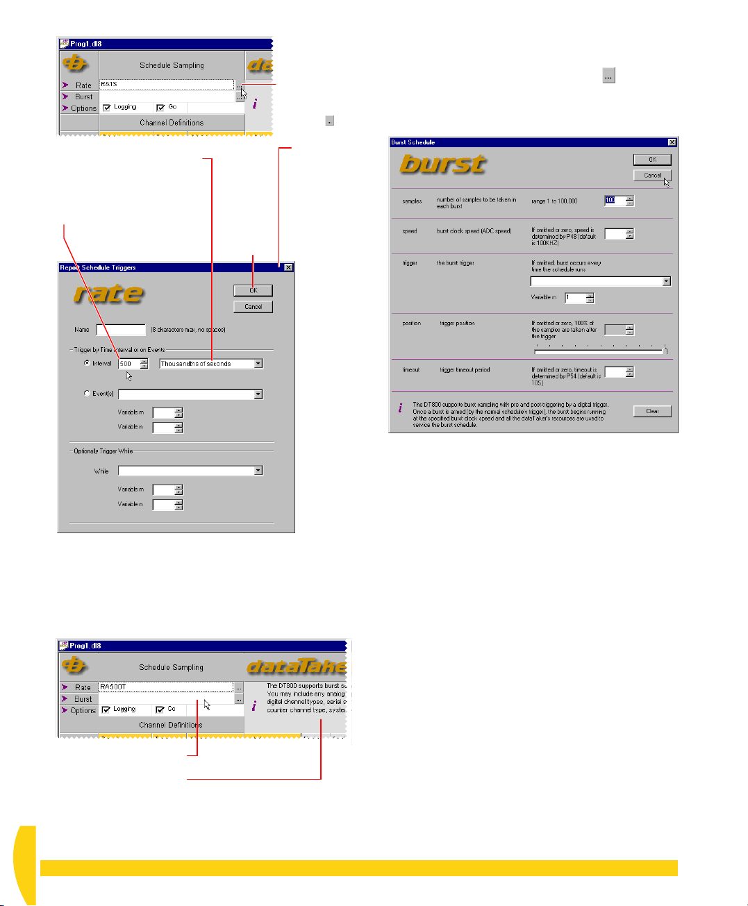
In the second Interval field,
➋
select Thousandths of
seconds (500 thousandths
of seconds = 0.5 seconds).
In the first Interval field,
➌
change the number to
500.
➍
Click
OK.
Click the
➊
Rate row’s
Properties
button .
The
Triggers
dialog box
opens.
You can use this technique to get information about
most items in the program builder.
e) Click the Burst row’s Configure button and, in
the dialog box that opens, look over the burst
schedule options available. When you’ve finished,
click
Cancel
to close the dialog box
FIGURE 29 Setting schedule A’s rate to 0.5 seconds
d) Single-click in the empty/white area of the Burst row
and notice the information text that appears in the
information area (on the right-hand side of the
program builder window) — Figure 28.
Single-click the Burst field
Burst information here.
F
IGURE 28 Information area example
to see
FIGURE 30 The burst schedule dialog box
We won’t use a burst schedule in this tutorial, but
you can read more about them in “Other Schedules
and Scans” in Part D of the
Manual
.
DT800 dataTaker User’s
f) In the Options row of the program builder, leave
Logging
and Go ticked.
Then when you send the program you’re currently
building to the DT800, these options instruct the
DT800 to run (
Go
) schedule A and to log its data.
UM-0071-A0
34 Getting Started with DT800
dataTaker
Page 35
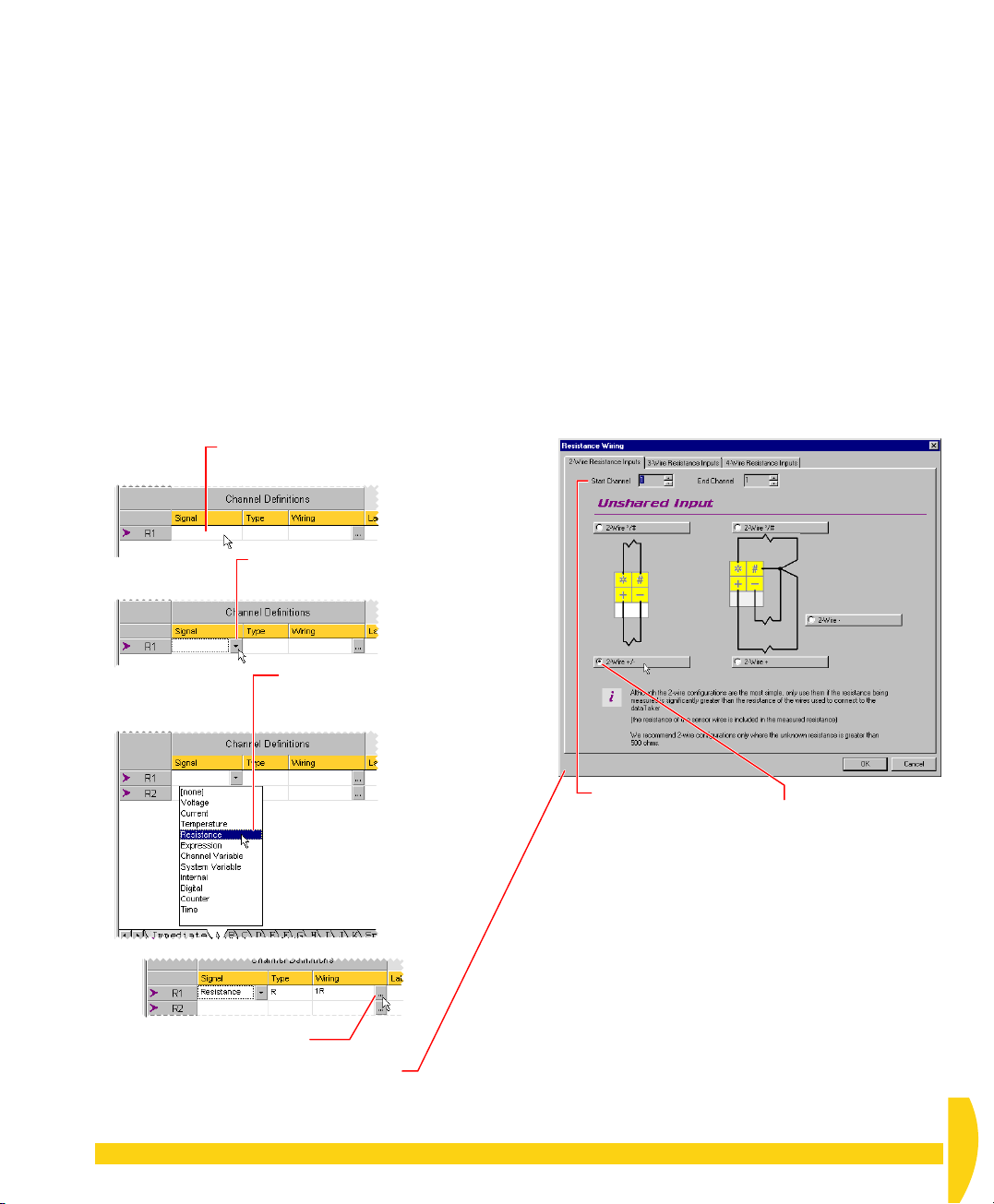
g) Now specify the channel you want schedule A to
read (the potentiometer channel) by following the
numbered steps in Figure 31.
When you’ve finished working through Figure 31,
you’ve specified your first schedule.
h) In DeLogger’s File menu, choose
Save Project
.
This ensures you won’t lose any of the work you’ve
just done.
i) Note that there are a number of other columns in
the program builder window.
They allow you to further affect how your input
channels and sensors are managed during
measurement, and how resulting data is processed
and manipulated. Click the Configure buttons and
the drop-down list buttons in these columns to see
more of what’s available.
Single-click in the Signal column of R1
➊
(the first row of the Channel Definitions
area).
Click the drop-down list button
➋
that appears in the Signal
column of R1.
You’ve just created and saved your first DeLogger
program. It contains one schedule, schedule A. When
you send it to the DT800, it will instruct the DT800 to
scan channel 1 every half-second as a resistance and
log the measurements.
Your program contains only one schedule because tab
A
(at the bottom of the program builder window) is the
only one in which you’ve assigned a channel. In later
chapters you’ll add
• another channel to schedule A
• another schedule, schedule B, to the program.
Click Resistance in the list
➌
(because you want the DT800
to read the potentiometer as a
resistance).
Check that both the
➎
Click the Configure button
➍
in the Wiring column.
The Resistance Wiring dialog box opens.
FIGURE 31 Specifying the potentiometer channel
Start Channel and
End Channel fields
contain 1 (you
connected the
potentiometer to
channel 1).
Notice the other wiring configurations and
➐
the information area across the bottom of the
dialog box.
Click 3-Wire Resistance Inputs and 4-
Wire Resistance Inputs at the top of the
dialog box. Examine these tabs but don’t
make any changes.
When you’ve finished, check that the settings
on the 2-Wire Resistance Inputs tab are
as described in ➎ and ➏ then click OK.
Check that the
➏
2-Wire +/– option is
selected (you made a
2-wire connection to
the + and – terminals
of channel 1).
CHAPTER 5YOUR FIRST PROGRAM: Create a Program 35
UM-0071-A0
Page 36
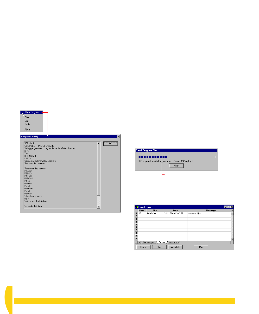
5-3
SEE WHAT
5-4
SEND THE
YOU’LL SEND
At any time, you can see the program you’re building
in command-line (text) format. This is probably only
useful if you’re familiar with the
programming language, but have a look at it now so
that you know this facility exists.
➲ Use the program builder’s right-click menu to
see the command-line form of your program.
To do this…
a)
Right
-click anywhere in the program builder
window (except the title bar).
A pop-up menu opens (Figure 32).
dataTaker
PROGRAM
Because you’re currently connected to the DT800 (you
did this in “Make the Software Connection” back on
page 19), all is now ready for you to send your
program.
➲ Send your program to the DT800.
To do this…
a) Make sure that
(single-click it if you’re not sure).
Always take care if you have more than one DT800
project builder in any project. DeLogger sends only
the program of the active
sure the correct program builder is front-most.
When a program builder is the front-most window,
the seventh menu from the left changes to
— see Figure 20 (page 27).
b) In the Program menu, choose
The Send Program File dialog box opens.
Prog1.dl8
program builder, so make
is the front-most window
Program
Send to Connection
.
Progress bar
F
IGURE 33 Send Program progress
The Event Logs window (Figure 34) may also open
to report that there is no current job (“program”) in
the DT800. See the “Event Logs” Extras panel.
FIGURE 32 See your program’s behind-the-scenes
commands
b) In the pop-up menu, choose
The Program Listing dialog box opens showing your
program line-by-line. Scroll down to see all of the
commands that constitute the program.
c) Click
UM-0071-A0
36 Getting Started with DT800
OK
to close the dialog box.
Show Program
.
FIGURE 34
errors and alarms
c) If the Event Logs window is open, click its
button.
Event Logs window displays messages,
Close
dataTaker
Page 37

d) Notice that the Acquiring LED on the DT800’s front
panel now flashes every half-second — that is,
every time the DT800 makes a measurement. (This
is in addition to the DT800’s three-second
“heartbeat” flash discussed in step b) in “Power the
DT800” on page 14.
Because your program instructed the DT800 to log
the measurements, the Logging LED also flashes
every half-second.
The DT800 is now running according to your
program, scanning channel 1 every half-second
and logging the value in its internal memory. We
won’t do it in this tutorial, but you could disconnect
from the DT800 now, leaving it operating
completely independent of the computer; this is how
many
dataTaker
s are used.
Remember…
When you send a program, you send all settings on
ever
y tab in the current program builder window —
see the bottom of Figure 26 (page 32). So, in addition
to scan schedules, you’re sending
• any span, polynomial and thermistor definitions
you’ve created on these tabs
• the DT800 configuration settings on the Switches,
Parameters and Global tabs.
Event Logs
The Event Logs window (Figure 34) displays
• messages on the Message tab
• errors on the Errors tab
• alarms on the Alarms tab.
If you tick
DeLogger opens this window every time an alarm
occurs.
If you tick
DeLogger opens this window every time an error
occurs.
If you tick
DeLogger opens this window every time a change
message is received from the DT800.
(You can alter the degree of this reporting — see
Configuration
Level
You can keep the Event Logs window permanently
open on your screen by ticking
View menu.
CHAPTER 5YOUR FIRST PROGRAM: Send the Program 37
Show Alarm Events
Show Error Events
Show Message Events
menu >
Defaults…
area.)
on the View menu,
on the View menu,
on the View menu,
>
Confirmation
View Events
on the
Switches and Parameters
Switches
use to configure the operation of a DT800.
Parameters
Both are described in Part H of the
dataTaker User’s Manual
Switches and parameters are primarily intended
for use when programming the DT800 directly (that
is, using the
and have little relevance when using DeLogger to
supervise the DT800.
are a group of internal settings you can
are another group of internal settings.
DT800
).
dataTaker
programming language)
UM-0071-A0
Page 38
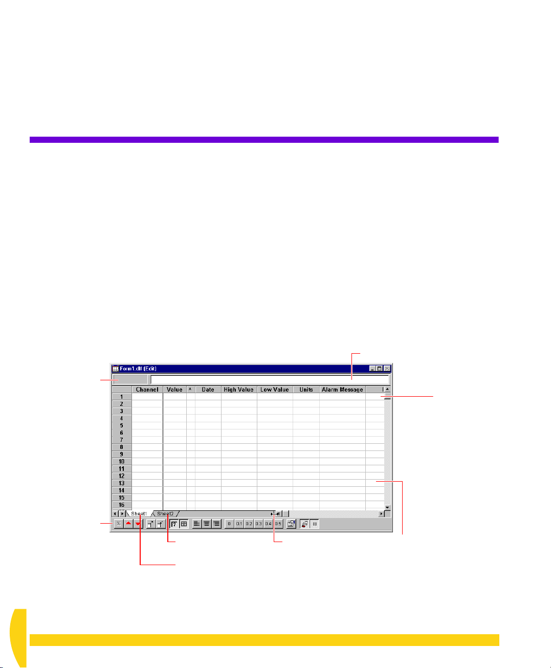
CHAPTER 6
S
EE
F
ORM
Y
OUR
W
D
ATA
INDOW
—
In this chapter
• you’re introduced to DeLogger’s form window —
page 38
• you use the form window to see data being returned
from the DT800 — page 41
• you automatically set the DT800’s date and time —
page 42.
Co-ordinates of the
current cell are
displayed here
(Edit Mode only)
6-1
DELOGGER’S FORM WINDOW
A DeLogger
or replay channels one row per channel (Figure 35).
In Microsoft Excel terminology, the form window is a
workbook
can add or delete worksheets at any time — explained
in the lower right-hand corner of Figure 35.)
form
window displays data from real-time
that initially contains one
Formula bar (Edit Mode only)
worksheet
. (You
Channel data
is displayed
one row
per
channel.
Form toolbar
The buttons
duplicate many
of the commands
on the Form menu.
figures 36
See
and 37.
FIGURE 35 A DeLogger form window
UM-0071-A0
38 Getting Started with DT800
Select a worksheet
by clicking its tab.
Rename a worksheet by
double-clicking its tab
(the Sheet Name dialog
box opens).
Drag the splitter bar
to shrink or enlarge
the tab space.
Double-right-click anywhere
in a worksheet to open it in
the Formula One Workbook
Designer, where additional
commands are available if
you need them (for example,
Sheet > Insert Sheet, Sheet >
Delete Sheet, Data > Recalc).
dataTaker
Page 39

Each channel’s row in the worksheet contains
• the channel’s latest value and its timestamp
• the channel’s highest value and lowest value
• a trend indicator (
U
p or Down), which shows
whether the latest value is above or below the
previous value
• the channel’s units
• any alarm message.
You can have as many form windows open as you
need. (To add a form window, choose
menu, then click the
bar when the window is in
To rename a column,
double-click the column
header (the Header Name
dialog box opens).
Form
button.)
“Edit” appears in the title
Edit Mode.
New
on the File
At any time, you can pause the incoming data and
print selected areas of the form.
Edit Mode On/Off
The form window has two distinct modes:
• Edit Mode — for configuring the form (
the Form menu is ticked)
• Run Mode — for viewing incoming data (
on the Form menu is un-ticked)
These modes are compared in Figures 36 and 37.
Connection
Schedule (A, B, C,…K)
Channel label (from the channel’s
Label column in the program builder)
Adjust the width of a column by dragging its right
border in the header row (the cursor changes to ↔).
Latest value
Trend indicator (Up/Down)
Timestamp of latest value
Maximum and minimum
channel values
Edit Mode
on
Edit Mode
To assign a different channel
to a row already in use,
double-click the row’s
Channel cell (the Select
Channel dialog box opens).
To replace the row number
with a custom name,
double-click the row number
(the Header Name dialog
To assign a channel to an
empty row, single-click the
row number or in the empty
channel column. In the
dialog box that opens,
select the channel you want
to display in that row.
FIGURE 36 A DeLogger form window in Edit Mode (Form menu >
box opens).
Set number of decimal places of selected cell(s)
Left, centre, or right align contents of selected cell(s)
Show/hide gridlines
Show/hide row and column headers
Scale view down (zoom out)
Scale view up (zoom in)
Reset all values in the Low Value column to zero (updated at the next scan).
Reset all values in the High Value column to zero (updated at the next scan).
Open the form window’s Properties
dialog box (to control the display of
realtime and/or logged data).
Edit Mode
Turn Edit Mode on/off
is ticked)
CHAPTER 6SEE YOUR DATA — FORM WINDOW: DeLogger’s Form Window 39
UM-0071-A0
Page 40

Scale view down (zoom out)
Scale view up (zoom in)
Reset all values in the Low Value column to zero (updated at the next scan).
Reset all values in the High Value column to zero (updated at the next scan).
Send the X schedule command (“polled” or “scan on host request” schedule).
Pause the return of data.
Turn Edit Mode on/off.
FIGURE 37 A DeLogger form window in Run Mode (Form menu >
Can’t See Live Data?
If the channel data in the Value column isn’t updating
as you think it should, check that
•
Edit Mode
form window is in Run Mode)
•
Pause
on the Form menu is un-ticked (that is, the
on the Form menu is un-ticked
The Form Menu
When a form window is DeLogger’s front-most
window, the seventh menu on DeLogger’s menu bar is
Form
(see Figure 20 on page 27). Commands on this
menu are specific to the form window, and some are
duplicated by buttons on the form toolbar (Figure 38).
• for real-time channels: DeLogger is connected to the
DT800, and the DT800 is running the program that
contains the channels you’ve specified to be
displayed in the form window
• for replay channels: the replay control panel is open and
showing the correct replay file’s name in its title bar.
Edit Mode on
Edit Mode is ticked on the Form menu.
Buttons available in Edit Mode
Edit Mode off (Run Mode)
Edit Mode is un-ticked on the Form menu.
Edit Mode
is un-ticked)
Edit Mode button depressed
Edit Mode button raised
Buttons available in Run Mode
IGURE 38 Buttons available on the form toolbar in Edit Mode and Run Mode
F
UM-0071-A0
40 Getting Started with DT800
dataTaker
Page 41
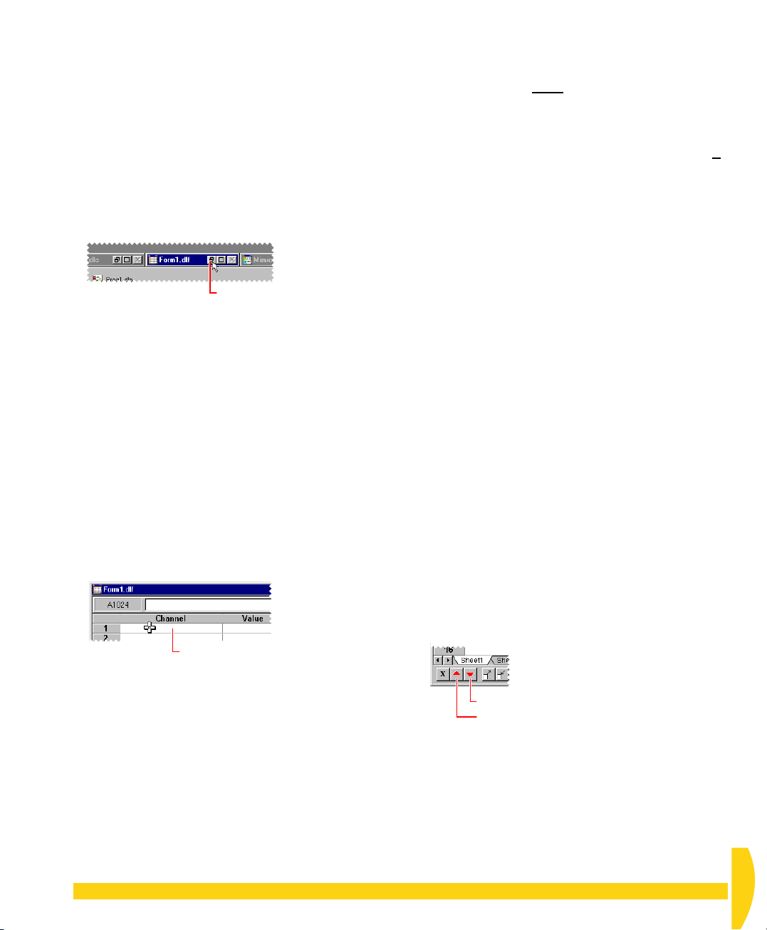
6-2
VIEW THE RETURNED DATA
➲ Use DeLogger’s form window to view the
real-time data that the DT800 is returning to
your computer.
To do this…
a) Locate the minimized form window at the bottom of
DeLogger’s main window — it’s named
— and click its Restore button.
Click Form1.dlf’s Restore button
to enlarge the text window.
F
IGURE 39 Restoring the form window
The form window is restored from its minimized
state.
b) Make sure that the form window is in Edit Mode.
Do this by checking for any of the following:
• the word “Edit” is present in the form window’s
title bar
• the formula bar is present at the top of the form
window (Figure 35)
• the Edit Mode button is in the pressed position
(Figure 38)
If the window is not in Edit Mode, choose
on the Form menu (or click the
c) Single-click in the
IGURE 40 Assigning a channel to row 1
F
Channel
Single-click
Edit Mode
column of row 1.
Form1.dlf
Edit Mode
button).
d) Notice that the name is composed of
• the Connection name
•
A
— the “schedule ID” (this is the default
schedule ID; it is not
ID you create in the program builder)
•
1R
— the “channel ID”, which itself is composed
of the “channel number”
channel type (this is the default channel ID; it is
replaced by any channel label you create in the
program builder — you’ll do this in “Add a
Channel Label” on page 55).
e) In the Select Channel for Row 1 dialog box,
highlight (one click) your channel name and click
OK
.
See also the “Clearing the Form Window” Extras
panel (page 42).
f) Turn Edit Mode
menu, or click/release the
while watching the form window’s Value column —
turn the knob on the potentiometer.
Returned data (resistance) appears in the Value
column and is updated every half-second.
g) Turn the knob in both directions and observe the
effect in the trend indicator column (shows
D
own) and the High Value and Low Value columns.
You may need to enlarge the form window or scroll
it horizontally to see these columns.
If turning the potentiometer knob fully anticlockwise
produces a maximum reading instead of a
minimum, reconnect the potentiometer using the
green and white wires instead of those used in
Figure 9 (page 15).
h) Experiment with the
buttons to see the effect they have on the readings in
the High Value and Low Value columns.
replaced by any schedule
1
and the Resistance
off
(un-tick
Edit Mode
Edit Mode
Reset High
and
on the form
button) and —
U
p or
Reset Low
The Select Channel for Row 1 dialog box opens. It
contains the name DeLogger has given to your
potentiometer channel.
CHAPTER 6SEE YOUR DATA — FORM WINDOW: View the Returned Data 41
IGURE 41 Reset High and Reset Low buttons
F
Reset Low button
Reset High button
UM-0071-A0
Page 42
6-3
SET THE
DT800’S DATE
AND TIME
Communicate again with the DT800 to set its date and
time to that of your computer.
➲ Use DeLogger’s Set Date/Time command.
To do this…
a) Notice the current date and time reported by the
DT800 in the form window’s
They may not be correct.
b) In the
c) Observe the
dataTaker
DeLogger communicates with the DT800 and sends
it your computer’s date and time (a progress dialog
box appears momentarily).
The DT800 is now returning the correct date and
time.
menu, choose
Date
column again.
Date
column.
Set Date/Time
.
Clearing the Form Window
To clear one or more rows in the form window,
highlight the row(s) —
work for multiple rows — then press
keyboard. A dialog box opens in which you select
what you want to clear:
• all (formats and values)
• formats only (special cell alignment, fonts, borders,
patterns and so on — see
• values only (leaves any special cell formatting
untouched)
FIGURE 42 Form window’s clear dialog box
UM-0071-A0
42 Getting Started with DT800
Shift+click
Form
and
Ctrl+click
Delete
menu >
on your
Format
)
dataTaker
Page 43
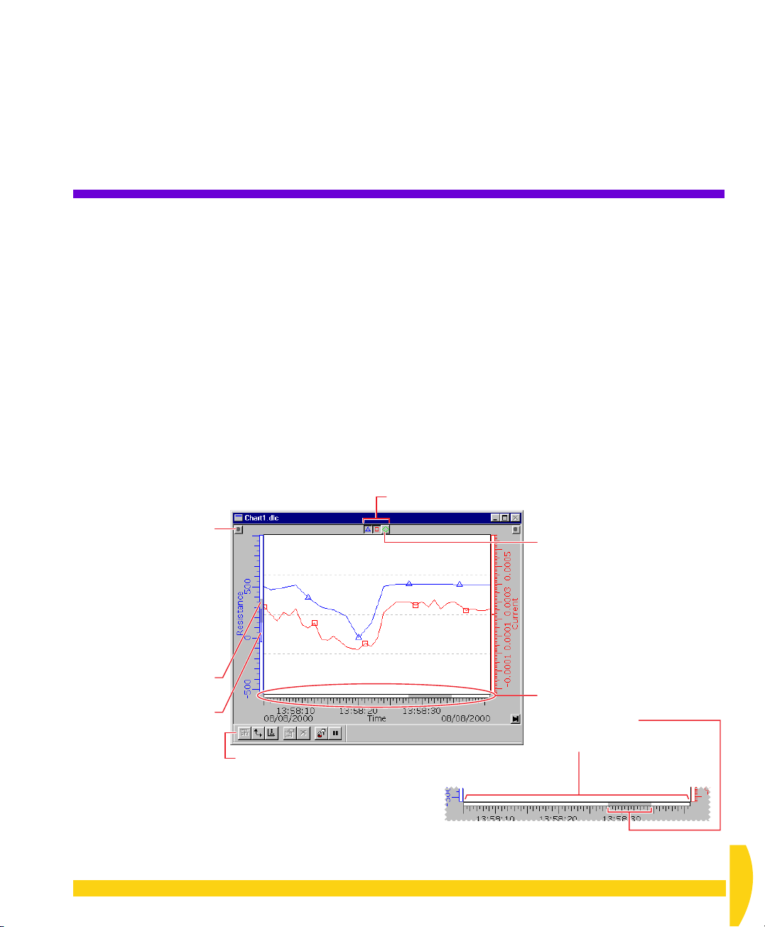
CHAPTER 7
S
EE
C
HART
Y
OUR
W
D
ATA
—
INDOW
DeLogger’s chart window turns your computer into a
powerful chart recorder.
In this chapter
• you’re introduced to DeLogger’s chart window —
page 43
• you chart data being returned from the DT800 —
page 48.
Drag a scale’s handle to
You can, for example, drag
the trend area, or place one
relocate the scale.
a scale to the other side of
above another (separates
the trends).
See
Figure 44.
7-1
DELOGGER’S CHART WINDOW
A DeLogger
one or more DT800 channels changes with time. See
Figures 43 and 44.
Incoming data from user-selected real-time or replay
channels is automatically plotted against time. New
data is plotted on the right-hand side of the trend area
and the trend graphs move from right to left, exactly
like the traces on a chart recorder.
You can display data from up to twelve channels in
each chart window — that is, twelve separate trend
graphs per chart window — and you can assign the
Individual graph show/hide buttons
chart
window displays how the value of
When you rest the mouse over a
graph’s Show/hide button, a popup information bar appears.
Figure 44.
See
vertical overview bar
shows the currently-visible
range (the gray bar)
maximum-to-minimum range
of the data (the
in proportion to the
maximum displayable
vertical range of the chart
(the full height
of the trend area).
FIGURE 43 A DeLogger chart window displays trend graphs (like a chart recorder).
CHAPTER 7SEE YOUR DATA — CHART WINDOW: DeLogger’s Chart Window 43
The
and the
I
bar)
Chart toolbar
The buttons duplicate commands
found on the Chart menu.
Figure 44.
See
Drag it from its docked position
to create a floating toolbar.
The horizontal overview bar
shows the currently-visible section of
data (the gray bar)
in proportion to the entire data set
(the full width of the trend area).
UM-0071-A0
Page 44
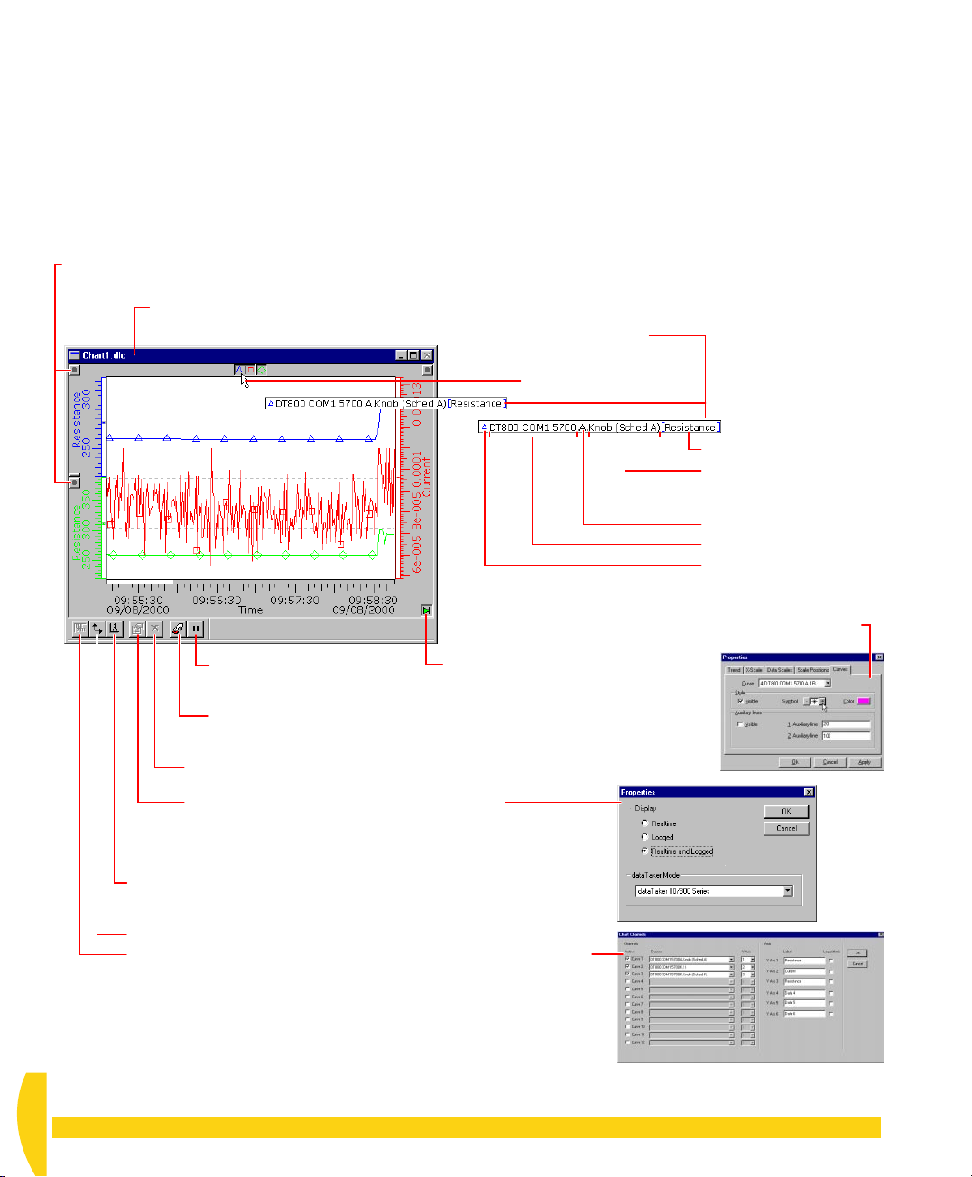
trends to as many as six Y axes (linear or logarithmic).
You can also open additional chart windows if
necessary. (To add a chart window, choose
the File menu, then click the
Chart
button.)
New
on
You can watch the trends update as the real-time or
replay data arrives, or you can home-in on a section of
the data already charted (while incoming data
continues to be recorded by the window).
Relocate a graph and its scale
by dragging its scale handle.
“Edit” appears after the window name in the
title bar when the window is in Edit Mode.
Pause the return of data.
Only available when the
window is in Run Mode.
Turn Edit Mode on/off.
Time (vertical) and data (horizontal) rulers allow you to
read precise coordinates from the trends (Figure 47).
Mouse Power
In a DeLogger chart window, you use the mouse to
select and scale sections of the trend graphs for
optimal viewing of regions you’re interested in. Figures
45 and 46 show how you do this.
An information bar
appears when you rest
the mouse over a graph’s
Show/hide button.
Axis label
Channel label (from the
channel’s Label column in
the program builder)
Schedule (A, B, C,…K)
Connection
The graph’s data point
symbol (if you’ve applied
one — double-click in the
trend area and go to the
Curves tab in the dialog
box that opens)
Play Chart button (and indicator).
The chart moves (like the paper in a
chart recorder) and new data enters
the right-hand side of the trend area
when when this button is pressed (lit).
Clear the chart window. Only available
when the window is in Edit Mode.
Open the chart window’s Properties dialog box
(to control the display of realtime and/or logged data).
Only available when the window is in Edit Mode.
Click the Auto Re-scale button to fit the trend graphs into the chart
window with maximum horizontal and vertical resolution (squeezes
all the data into the window).
Rotate the graphs so that they move from top to bottom.
Select channels to be plotted in this chart window (the Chart Channels
dialog box opens). Only available when the window is in Edit Mode.
FIGURE 44 More features of the DeLogger chart window
UM-0071-A0
44 Getting Started with DT800
dataTaker
Page 45
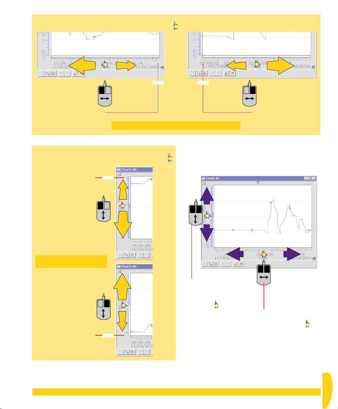
HORIZONTAL SCALING
Rest the mouse over the horizontal scale (the cursor changes to ) then click and drag as described here.
Horizontal scaling from the right
EXPAND
COMPRESS
FIXED FIXED
Move the left end of
the scale by dragging
horizontally with the left
mouse button pressed.
The right-hand end of the scale
stays fixed while you drag.
For finer control, start dragging further from the fixed end.
VERTICAL SCALING
Rest the mouse over the vertical scale (the cursor changes to )
then click and drag as described here.
The upper end of the scale
FIXED
stays fixed while you drag.
Move the lower end of
COMPRESS
the scale by dragging
vertically with the left
mouse button pressed.
Vertical
scaling
from the
top
Horizontal scaling from the left
COMPRESS
EXPAND
Move the right end of
the scale by dragging
horizontally with the right
mouse button pressed.
The left-hand end of the scale
stays fixed while you drag.
UPDOWN
Shifting
EXPAND
RIGHTLEFT
For finer control, start dragging
further from the fixed end.
VERTICAL SHIFTING
Rest the mouse
over the vertical
scale (the cursor
changes to ),
then hold down
both mouse buttons
and drag vertically.
HORIZONTAL SHIFTING
Rest the mouse over the horizontal
scale (the cursor changes to ),
then hold down both mouse
buttons and drag horizontally.
Move the upper end of
the scale by dragging
vertically with the right
mouse button pressed.
The lower end of the scale
FIXED
EXPAND
COMPRESS
Vertical
scaling
from the
bottom
stays fixed while you drag.
FIGURE 45 Chart window mouse power 1— horizontal/ver tical scaling, and horizontal/vertical shifting
CHAPTER 7SEE YOUR DATA — CHART WINDOW: DeLogger’s Chart Window 45
UM-0071-A0
Page 46
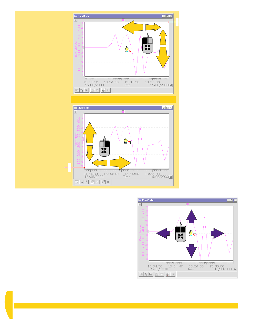
DIAGONAL SCALING
Drag inside the trend area
(instead of along the scales)
with the appropriate mouse
button pressed.
EXPAND
COMPRESS
COMPRESS
The upper right-hand corner
FIXED
stays fixed while you drag.
The lower left-hand corner
stays fixed while you drag.
Re-scale from the upper right-hand corner
EXPAND
by dragging diagonally
with the left mouse button pressed.
For finer control, start dragging further from the fixed corner.
Re-scale from the lower left-hand corner
by dragging diagonally
with the right mouse button pressed.
EXPAND
COMPRESS
COMPRESS
FIXED
EXPAND
UPDOWN
DIAGONAL SHIFTING
Drag inside the trend area
(instead of along the scales)
with both mouse buttons
pressed.
FIGURE 46 Chart window mouse power 2— diagonal scaling and diagonal shifting
UM-0071-A0
46 Getting Started with DT800
RIGHTLEFT
dataTaker
Page 47

Edit Mode On/Off
The chart window has two distinct modes:
• Edit Mode — for configuring the chart (
Edit Mode
on the Chart menu is ticked)
• Run Mode — for viewing incoming data or previous
sections of the graphs (
Edit Mode
on the Chart menu
is un-ticked)
Graphs Not Updating?
If your trend graphs are not updating in the chart
window, check that
•
Edit Mode
chart window is in Run Mode)
•
Pause
• for real-time channels: DeLogger is connected to the
DT800, and the DT800 is running the program that
contains the channels you’ve specified to be
displayed in the chart window
• for replay channels: the replay control panel is open
and showing the correct replay file’s name in its title
bar.
on the Chart menu is un-ticked (that is, the
on the Chart menu is un-ticked
The Chart Menu
When a chart window is DeLogger’s front-most
window, the seventh menu on DeLogger’s menu bar is
Chart
(see Figure 20 on page 27). Commands on this
menu are specific to the chart window, and some are
duplicated by buttons on the chart window’s toolbar
(see Figures 43 and 44).
appears beside the cursor when it’s over the ruler.
Drag the time ruler from
the left or right vertical axis.
An information bar shows the
time or data coordinate.
FIGURE 47 Chart window rulers for displaying precise time and data coordinates
Drag the data ruler from the
top or bottom horizontal axis.
CHAPTER 7SEE YOUR DATA — CHART WINDOW: DeLogger’s Chart Window 47
UM-0071-A0
Page 48
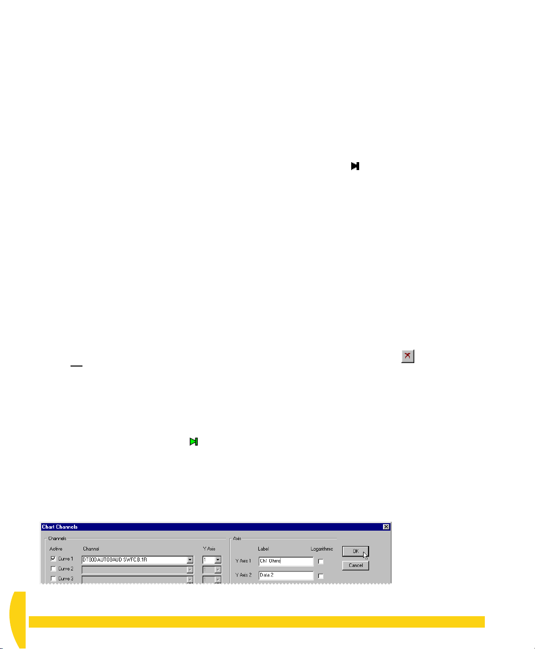
7-2
CHART THE RETURNED DATA
➲ Display data from the potentiometer channel
in DeLogger’s chart window.
To do this…
a) Locate the minimized chart window at the bottom of
DeLogger’s main window — it’s named
— and click its Restore button.
The chart window is restored from its minimized
state.
b) Make sure that the chart window is in Edit Mode.
c) In the Chart menu (seventh menu from the left),
choose
The Chart Channels dialog box opens (Figure 48).
d) In the Chart Channels dialog box:
The dialog box closes leaving the chart window
almost ready to receive channel 1’s data.
Note the axis text
the chart window.
e) Make sure that the
hand end of horizontal axis) is pressed/green.
Select Channels…
Active
i. Under
ii. Open the
becomes available and choose the
potentiometer channel.
iii. Leave the
iv. Under
field with
appear on the vertical/data axis of the chart).
v. Do not
vi. Click
, tick
Channel
Y Axis
Label
, replace
Ch1 Ohms
tick under
OK
.
.
Curve 1
drop-down list box that
set to 1.
Logarithmic
Ch1 Ohms
Play Chart
.
Data 1
in the
(or any text you want to
on the left-hand side of
button ( at the right-
.
Chart1.dlc
Y Axis 1
f) Turn Edit Mode
menu, or click the
the chart window) and watch the chart window
while you turn the potentiometer’s knob.
The data points are plotted in the trend area and
joined with straight-line segments as the chart moves
from right to left.
g) In the Chart menu, choose
All the data returned to the chart window so far is
compressed into view in the trend area.
h) Click the
button turns black ).
Note that stopping the chart does not stop the flow
of data into the window, whereas the
command does stop the flow — no data is stored in
the window’s buffer when the window is paused.
This is also true for the other windows that can be
paused (form, mimic and text).
i) Use your mouse as described in Figures 45 and 46
to scale and shift the trace.
j) Drag the time and data rulers into the trend area as
shown in Figure 47.
Notice the information box that appears for each
ruler. You can drag the box to your preferred
position in the DeLogger window.
k) Turn Edit Mode
menu (or click the
All the data returned to the chart window is deleted.
l) Continue to experiment in the chart window if you
want. Remember that Edit Mode must be
incoming data.
off
Play Chart
on
(un-tick
Edit Mode
then choose
Clear
Edit Mode
button on the bottom of
Auto Re-scale
button to stop the chart (the
button ).
on the Chart
Clear
from the Chart
.
Pause
off
to plot
FIGURE 48 Assigning a channel to the chart window
UM-0071-A0
48 Getting Started with DT800
dataTaker
Page 49
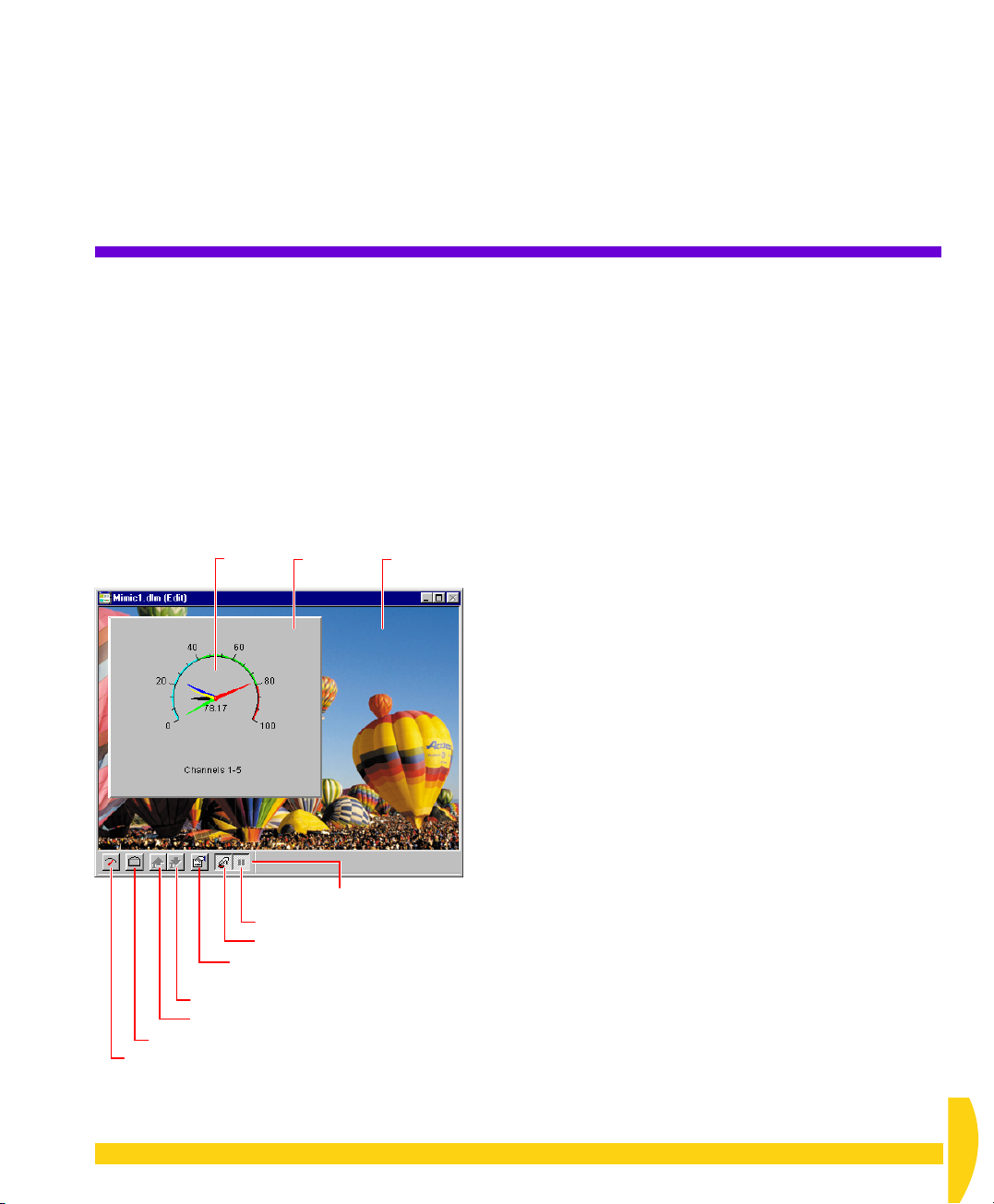
CHAPTER 8
S
EE
Y
OUR
D
ATA
—
M
DeLogger also allows you to present data as a moving
analog needle on a meter panel. (And if you upgrade
to DeLogger Pro, you’ll have access to other meter
types, as well as buttons that perform actions.)
In this chapter
• you’re introduced to DeLogger’s mimic (meter)
• you create a meter and use it to display data —
• you play a replay file to a meter — page 51
• you add a graphic to a meter panel — page 52
•
FIGURE 49 A typical DeLogger mimic window
IMIC
window — page 49
page 50
you practise disconnecting from the DT800 — page 53
Meter Panel Background
Open the mimic window’s
Properties dialog box.
Scale text down.
Scale text up.
Load a picture.
Create a meter panel and assign up to
five channels to it.
W
Pause the return of data.
Turn Edit Mode on/off.
.
INDOW
image
Mimic toolbar
8-1
DELOGGER’S MIMIC WINDOW
A DeLogger
represent data as a panel containing one or more
needle (arc) meters on your computer screen.
You can have as many mimic windows open as you
need (limited only by computer memory and speed).
To add a mimic window, choose
menu, then click the
.
Edit Mode On/Off
The mimic window has two distinct modes:
• Edit Mode — for creating, moving and resizing
mimics, and for assigning channels (
the Mimic menu is ticked)
• Run Mode — for displaying incoming data (
Mode
Meters Not Updating?
If your meters are not updating in the mimic window,
check that
•
Edit Mode
the mimic window is in Run Mode)
•
Pause
• for real-time channels: DeLogger is connected to the
DT800, and the DT800 is running the program that
contains the channels you’ve assigned for display
by the meters
• for replay channels: the replay control panel is open
and showing the correct replay file’s name in its title bar.
The Mimic Menu
When a mimic window is DeLogger’s front-most
window, the seventh menu on DeLogger’s menu bar is
Mimic
menu are specific to the chart window, and some are
duplicated by buttons on the mimic window’s toolbar
(see Figure 49).
mimic
window (Figure 49) lets you
New
on the File
Mimic
button.
Edit Mode
on the Mimic menu is un-ticked)
on the Mimic menu is un-ticked (that is,
on the Mimic menu is un-ticked
(see Figure 20 on page 27). Commands on this
on
Edit
CHAPTER 8SEE YOUR DATA — MIMIC WINDOW: DeLogger’s Mimic Window 49
UM-0071-A0
Page 50
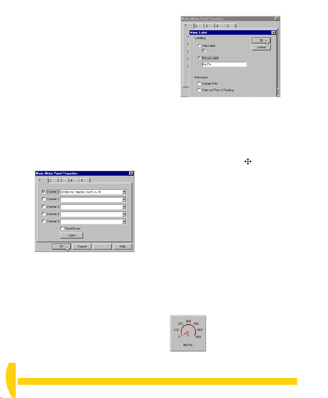
8-2
DISPLAY
RETURNED DATA
IN A METER
➲ Create a meter panel and assign the
potentiometer channel to it.
To do this…
a) Locate the minimized meter window
and click its Restore button.
b) Make sure that the mimic window is in Edit Mode.
c) In the Mimic menu (seventh from the left), choose
Needle Meters…
The Mimic Meter Panel Properties dialog box
opens.
d) On tab 1:
i. Open the first drop-down list box and choose
the potentiometer channel.
FIGURE 50 Assigning a channel to a meter’s
needle
ii. Tick
iii. Click the
iv. In the Mimic Label dialog box that opens
v. Click
The new meter panel appears in the top left-hand
corner of the mimic window.
e)
Single
A striped border appears around the panel to show
that it’s selected.
Panel Border
(Figure 51), select
(or any text you want to appear beneath
Pot.
the meter), then click
Properties dialog box.
-click anywhere within the meter panel.
.
(Figure 50).
Label
button (Figure 50).
Manual Label
OK
.
OK
again to close the Mimic Meter Panel
Mimic1.dlm
and type
My
FIGURE 51 Creating a meter label
f) Drag the anchor point in lower right-hand corner
down and to the right to enlarge the panel to
approximately double its original size.
The mouse pointer changes to a double-ended
diagonal arrow when you’re over the anchor point.
g) Hold the mouse pointer anywhere within the panel.
When the pointer changes to , drag the panel
into the centre of the mimic window.
h) Click outside the panel to de-select it.
➲ Change the range of the meter to suit your
potentiometer.
To do this…
a)
Double
-click the meter (in the centre of the meter, not
the surrounding panel).
b) In the Meter Parameters dialog box that opens:
i. Type
ii. Type
iii. Click
Your meter should now look like Figure 52.
FIGURE 52 The meter before changing its alarm
bands
600
in the To field of the
This suits your potentiometer, which has a
maximum resistance of approximately 550
ohms.
100
in the
Step
field of the
The tick marks will appear 100 ohms apart
around the meter.
OK
.
Range
Ticks
area.
area.
UM-0071-A0
50 Getting Started with DT800
dataTaker
Page 51
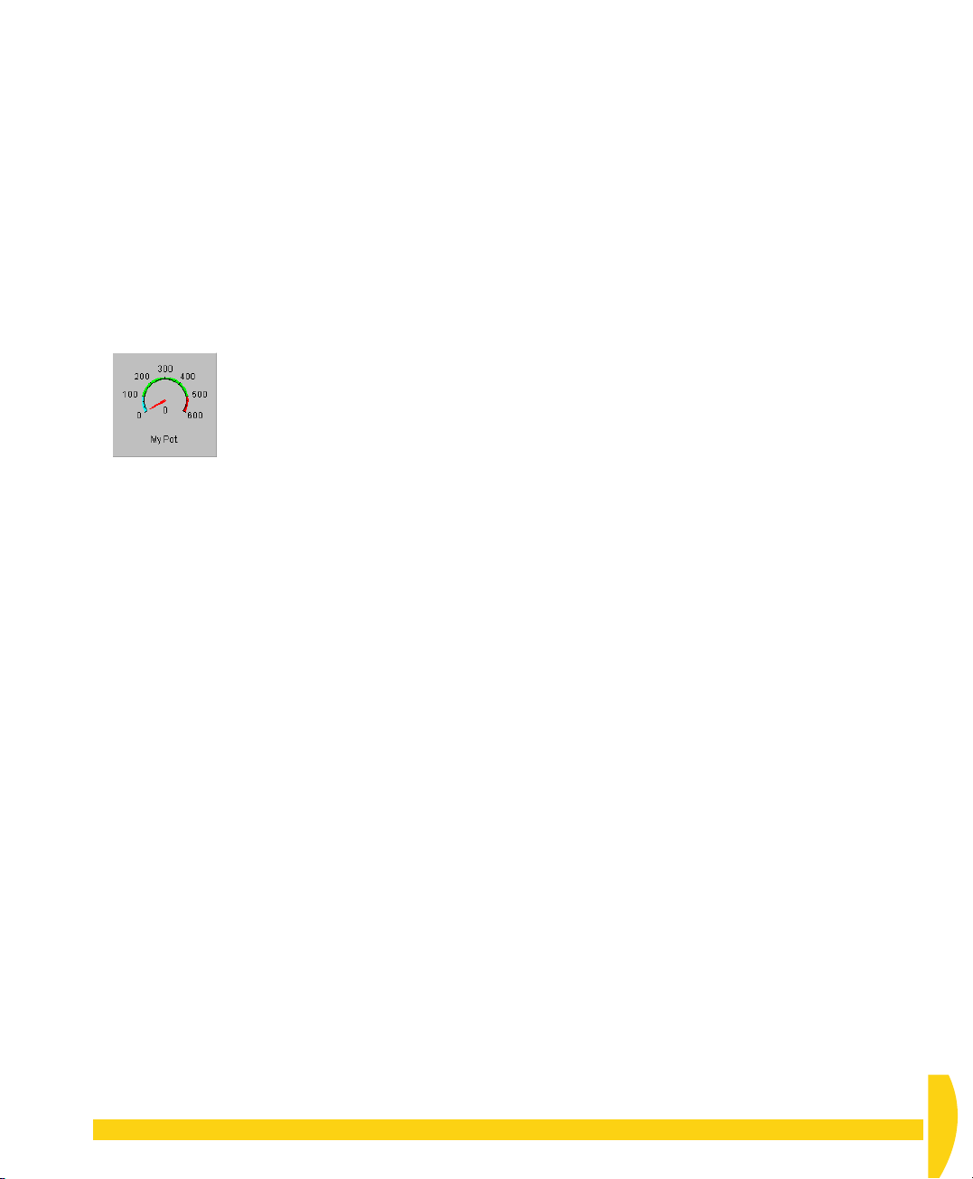
➲ Change the meter’s alarm bands.
To do this…
a)
Double
-click the meter again.
b) In the Meter Parameters dialog box that opens, click
the
Alarm Attributes…
c) In the Alarm Attributes dialog box that opens:
500
i. Type
ii. Type
iii. Click
d) Click
OK
dialog box.
Your meter should now look like Figure 53.
FIGURE 53 The finished meter
in the
100
in the
OK
.
again to close the Meter Parameters
button.
High
Low
field (
field (
Value
Value
column).
column).
➲ Use the meter to display data from the
channel assigned to it (the potentiometer
channel).
To do this…
a) Turn Edit Mode
the meter while you turn the potentiometer’s knob.
The needle moves and the value shown under the
needle changes according to the incoming data.
b) Look at the form window and the chart window also
and continue turning the knob.
Data in all three views updates every time schedule
A makes a scan (every half-second).
off
for the mimic window and watch
8-3
REPLAY A FILE TO
A METER
Data can also come from a file — a
DeLogger. You use a special DeLogger Connection —
a
replay Connection
Replay File” on page 30.
— to do this. See “Replay Data,
replay file
— into
➲ Open a replay Connection.
To do this…
a) In the Connections menu, choose
b) In the Replay Connection dialog box that opens,
highlight
c) In the Select Replay File dialog box that opens,
highlight
The example replay files were placed here when
you installed DeLogger.
The file replay control panel opens ready for you to
start a replay of
d) Familiarize yourself with Figure 25 on page 30,
which explains the various components of the
replay control panel.
MyFile
and click OK.
Example.dlr
Example.dlr
and click
.
Play…
Open
.
.
➲ Create another meter panel and assign a
replay channel to it.
To do this…
a) Make sure that the mimic window is in Edit Mode.
b) In the Mimic menu, choose
c) On tab 1:
i. Open the first drop-down list box and notice
that channels from the replay file Connection
are now available (in addition to those from the
Connection to the DT800).
ii. From the list, choose
OK
iii. Click
The new meter panel appears in the top left-hand
corner of the mimic window.
d) Drag the meter’s panel to enlarge it.
e) Click outside the panel to de-select it.
.
Needle Meters…
MyFileB.21CV
.
.
CHAPTER 8SEE YOUR DATA — MIMIC WINDOW: Replay a File to a Meter 51
UM-0071-A0
Page 52

➲ Activate the mimic window and play the
replay file.
To do this…
a) Turn Edit Mode
b) Drag the replay control panel to a position that
allows you to see it as well as the mimic window.
c) In the control panel, click the
the second meter.
The needle of the second meter displays data as it is
received from the replay file.
d) Increase the speed of the replay and watch the
effect on the needle.
e) Use the
panel.
f) During replay, turn the potentiometer’s knob and
observe that each meter displays its appropriate
data.
Pause, Reset
off
for the mimic window.
Play
button and watch
and
Play
buttons in the control
8-4
You can add graphics to a mimic window as a
background or, for example, to create a flowchart that
incorporates DeLogger meters.
ADD A GRAPHIC
➲ Load a graphic into the mimic window.
To do this…
a) Turn Edit Mode on for the mimic window.
b) In the Mimic menu, choose
c) In the dialog box that opens, click the Browse button
at the right-hand end of the
d) In the Select Picture File dialog box that opens,
select
BAKDROP5.bmp
BAKDROP5.bmp is a blue gradient.
OK
e) Click
dialog box.
The image appears in the mimic window.
f)
Single
right-hand corner to fill the mimic window.
g) With the image still selected, choose
Arrange
h) With the image still selected, choose
Lock
The background image is locked behind your
meters.
to close the Mimic Picture Properties
-click the image to select it, then drag its lower
>
Send to Back
.
Picture…
File
field.
and click
.
.
Open
Mimic
Mimic
.
menu >
menu >
Tip When using a graphic behind your meters, load
the graphic first (and lock it) so that subsequent meter
panels automatically overlay the background.
UM-0071-A0
52 Getting Started with DT800
dataTaker
Page 53
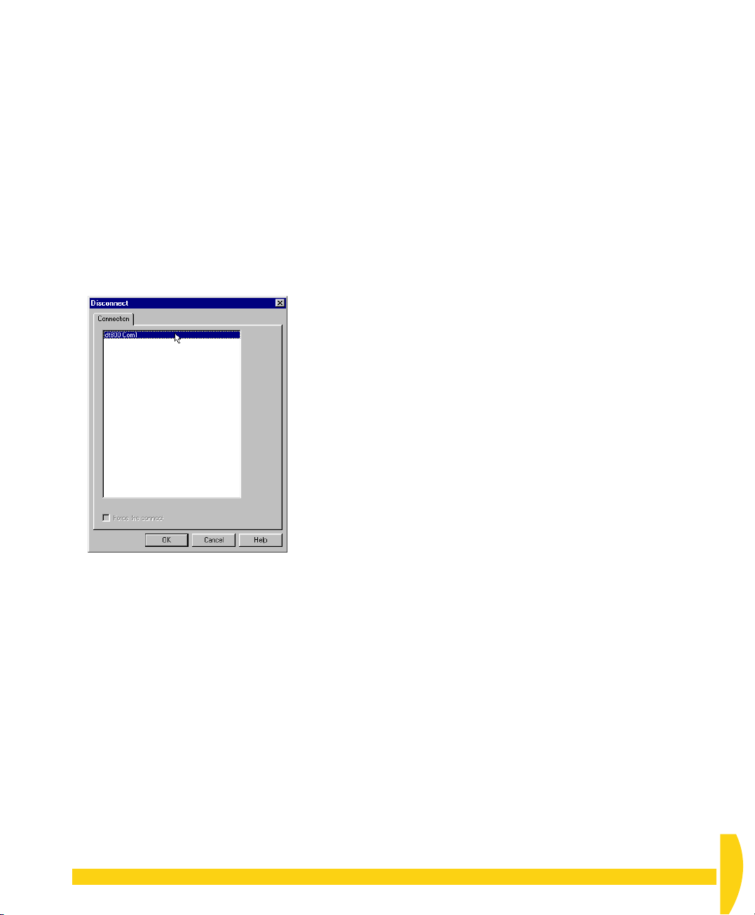
8-5
Although you need to be connected to the DT800 in
order to complete this tutorial, we’ll get you to
disconnect here and then reconnect in the next chapter
— just for practice.
DISCONNECT
➲ Carry out a software disconnection from
your DT800.
To do this…
a) In DeLogger’s Connections menu, choose
Disconnect…
b) In the Disconnect dialog box that opens, highlight
(one click)
.
dt800 Com1
and click OK.
FIGURE 54 Disconnecting
There is no longer a link between DeLogger and
your DT800, but the DT800 is still running
according to your program — scanning channel 1
every half-second and logging the results into its
internal memory.
c) Confirm that data is no longer being returned from
the DT800 by looking at the form window, the chart
window or the mimic window.
These windows are not updated when DeLogger is
disconnected from the DT800.
CHAPTER 8SEE YOUR DATA — MIMIC WINDOW: Disconnect 53
UM-0071-A0
Page 54

CHAPTER 9
E
XTEND
Y
OUR
P
ROGRAM
In this chapter you’ll learn more about DeLogger and
your DT800 by
• altering schedule A’s rate — page 55
• adding your own label to the potentiometer channel
— page 55
• adding channels to schedule A using more of the
program builder’s features — page 56
• reassigning the form, chart and mimic windows —
page 59
• using a DeLogger text window — page 60
• adding an alarm to the potentiometer channel —
page 63
• adding another schedule to your program —
page 64.
9-1
Connect to the DT800 now so that all is ready to send
your program after each revision you make.
RECONNECT
➲ Reconnect to your DT800 (use the same
Connection as last time).
To do this…
a) Repeat the step “Connect to the DT800 using dt800
Com1.” on page 20.
b) Confirm the re-connection by checking that the
information in the form window is again being
regularly updated.
UM-0071-A0
54 Getting Started with DT800
dataTaker
Page 55
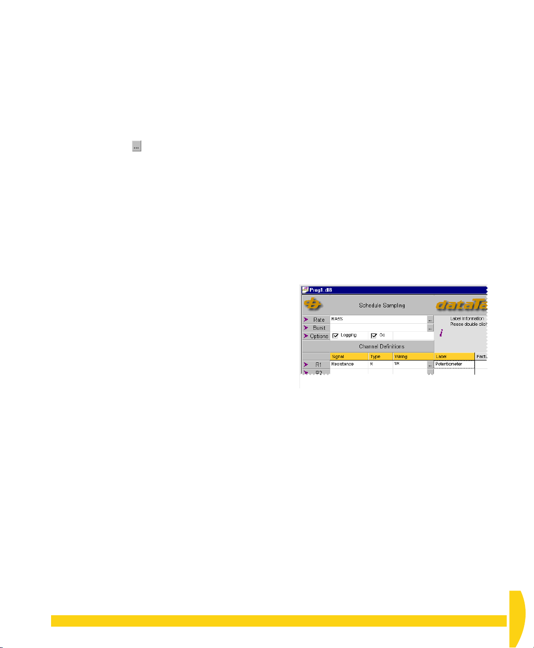
9-2
FIGURE 55 Schedule A after program changes
CHANGE
9-3
ADD A CHANNEL
SCHEDULE A’S
RATE
➲ Change schedule A’s rate to 5 seconds.
To do this…
a) In tab A of the program builder, click the Rate row’s
Configure button . (Look back at Figure 29 on
page 34 for a reminder.)
The Triggers dialog box opens.
b) In the second Interval field, select
drop-down list.
c) In the first Interval field, change the number to
d) Click
e) In DeLogger’s File menu, choose
OK
.
In the Rate row of tab A, you’ll now see
(
R
eport schedule A, 5 Seconds).
Seconds
Save Project
from the
RA5S
5
.
.
LABEL
Next, add your own label to the potentiometer channel
(channel 1 of the DT800). You’ll see later where this
becomes useful.
➲ Give channel 1 the label Potentiometer
(or any name you want).
To do this…
a)
Single
-click in the
the related message that appears in the information
area of the program builder window.
b)
Double
-click in the
Row 1 (
DT800 to be read as a resistance.
c) Type
Channel 1 now has a expressive name, and
schedule A should now look like Figure 55.
R1
Potentiometer
Label
column of row 1 and notice
Label
column of row 1.
) is where you defined channel 1 of the
.
CHAPTER 9EXTEND YOUR PROGRAM: Change Schedule A’s Rate 55
d) In DeLogger’s File menu, choose
Save Project
.
UM-0071-A0
Page 56

9-4
ADD MORE CHANNELS TO SCHEDULE A
Now add more DT800 channels to schedule A.
Because they’re all on schedule A, they’ll all be read
every 5 seconds.
You’ll add
• channel 6 — to be read as a voltage
• channel 7 — to be read as a voltage
• channels 9 to 12 — to be read as thermocouples.
If you have actual sensors you want to connect them to
these channels, do it now. If you haven’t, don’t worry
— you’ll still be able to work through this tutorial and
see data returned (although the data will be nonsense).
➲ Use row 2 (R2) to instruct the DT800 to
read its channel 6 as an unshared differential
+/– voltage.
To do this…
a) Single-click in the
b) Click the drop-down list button that appears and
choose
c) In the
button .
The Voltage Wiring dialog box opens for row 2
(Figure 56).
d) In the
Wiring dialog box, click the up button until the
field contains
Notice that the number in the End Channel field also
changes to 6.
e) Leave the
(Figure 56) and click
Channel 6’s channel definition (R2) should look like
Figure 60 on page 58.
Voltage
Wiring
Start Channel
Differential +/–
Signal
column of R2.
.
column of R2, click the Configure
field at the top of the Voltage
6
.
configuration selected
OK
.
Set the Start Channel
to 6.
Leave the Differential +/–
option selected.
F
IGURE 56 Defining channel 6 for voltage measurement
UM-0071-A0
56 Getting Started with DT800
dataTaker
Page 57
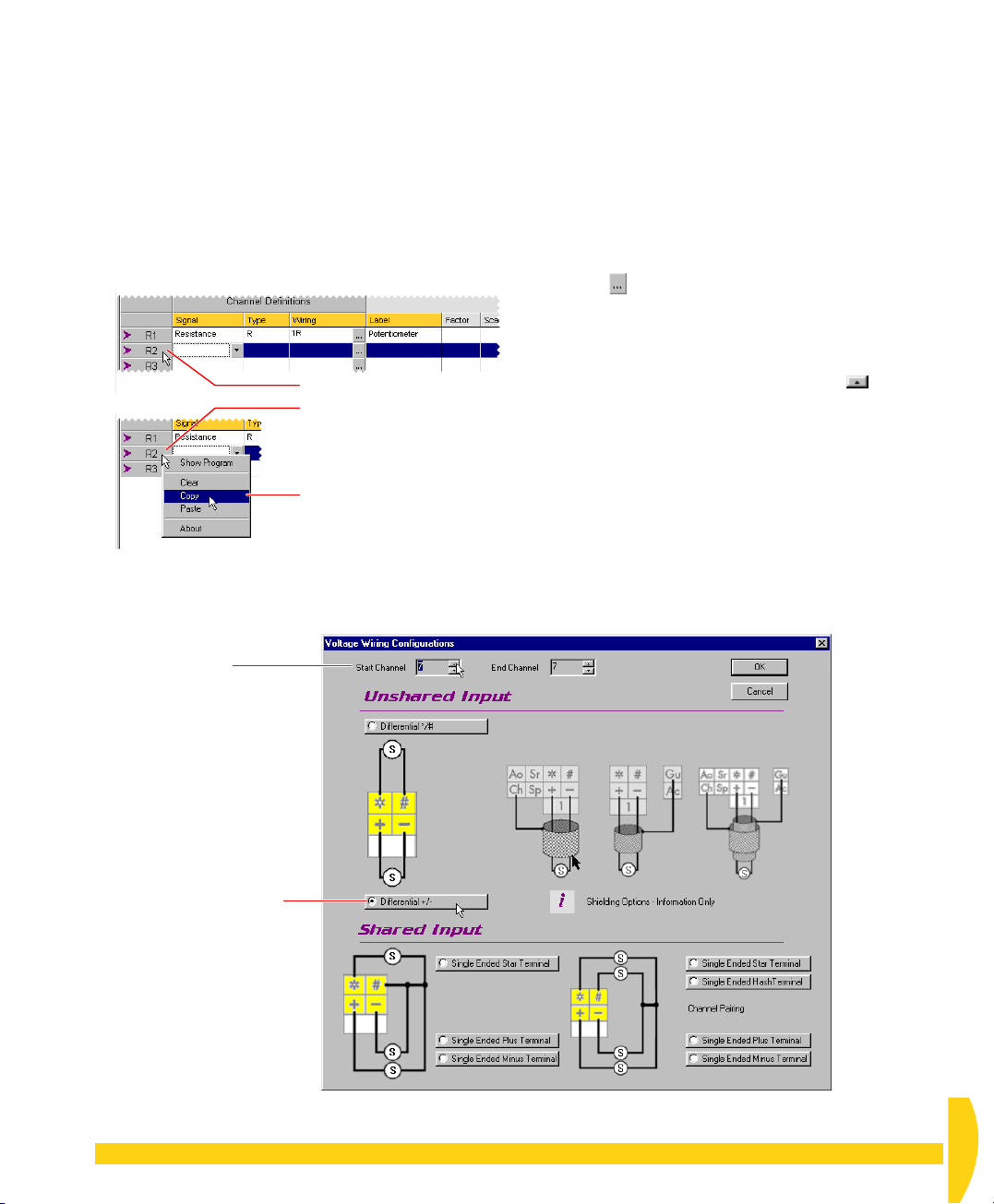
➲ Use copy and paste to duplicate row 2’s
definition into row 3. Then modify row 3 to
instruct the DT800 to read channel 7 as an
unshared differential +/– voltage.
To do this…
a) Select all of row 2 by clicking its
box containing
b) Now
right
R2
) — see Figure 57.
-click the row label of row 2.
A menu appears (Figure 57).
c) In the right-click menu, choose
FIGURE 57 Select R2, copy, and paste into R3
row label
Copy
Left-click to select the row.
➊
Right-click to reveal the
➋
menu.
Choose Copy.
➌
(the gray
.
All of row 2’s cells are copied to the clipboard.
d) Click the
e)
Right
f) In the menu that appears, choose
row label
of row 3 to select the entire row.
-click the row label of row 3.
Paste
.
Row 3 and row 2 are now identical.
Clear
Notice also the
command on the right-click
menu. You use this to delete all information from a
selected row.
g) In the
Wiring
column of R3, click the Configure
button .
The Voltage Wiring dialog box opens for row 3
(Figure 58).
h) In the
Start Channel
field at the top of the Voltage
Wiring dialog box, click the up button until the
field contains
i) Leave the
and click
7
.
Differential +/–
OK
.
configuration selected
Channel 7’s channel definition (R3) should look like
Figure 60.
Set the Start Channel
to 7.
Leave the Differential +/–
option selected.
F
IGURE 58 Defining channel 7 for voltage measurement
CHAPTER 9EXTEND YOUR PROGRAM: Add More Channels to Schedule A 57
UM-0071-A0
Page 58
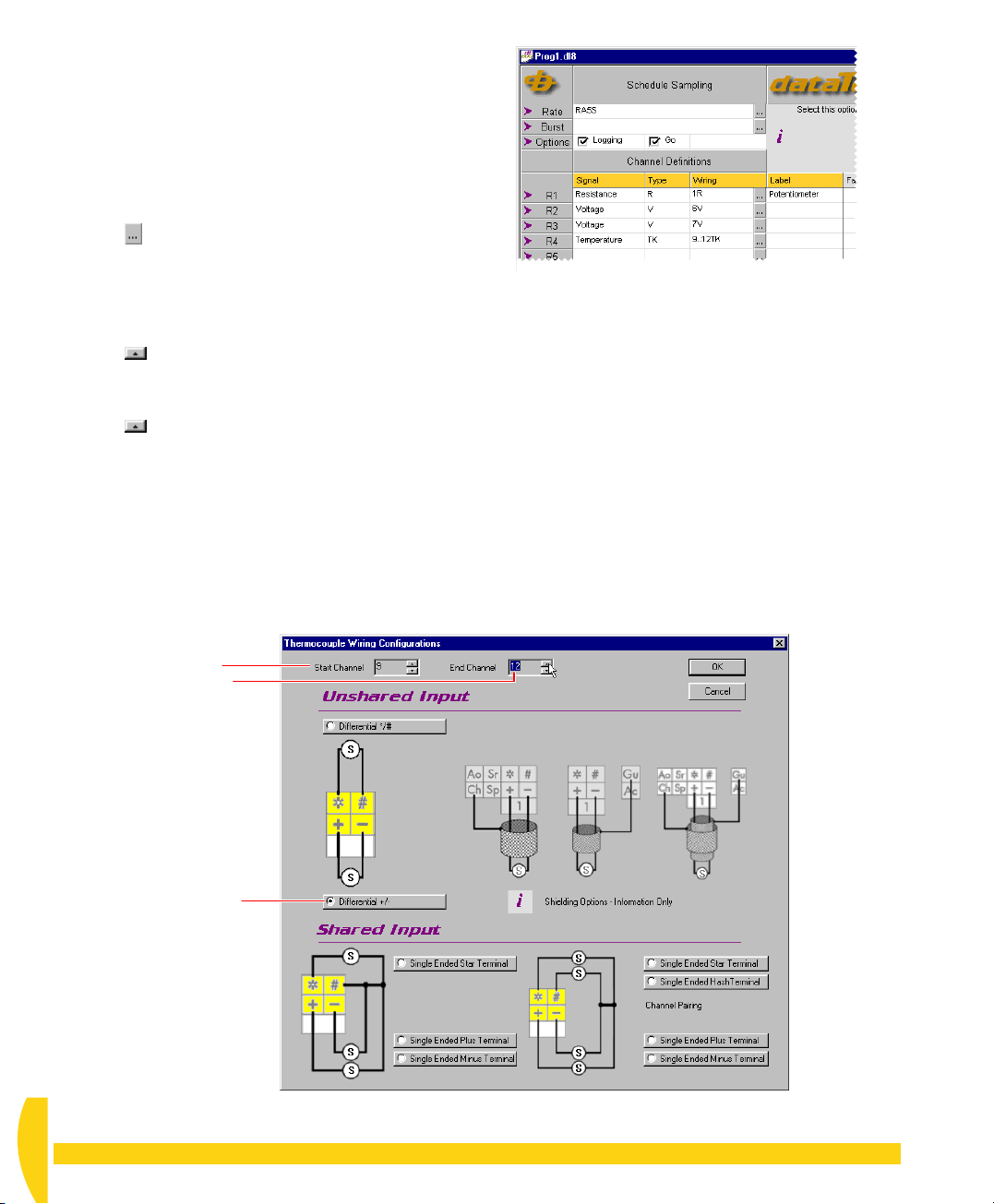
➲ Use row 4 (R4) to instruct the DT800 to
read channels 9 to 12 as thermocouples.
To do this…
a) Single-click in the
b) Click the drop-down list button that appears and
choose
c) In the
Temperature
Wiring
button .
The Thermocouple Wiring dialog box opens for row
4 (Figure 59).
d) In the
Start Channel
Thermocouple Wiring dialog box, click the up
button until the field contains
e) In the
End Channel
Thermocouple Wiring dialog box, click the up
button until the field contains
f) Leave the
and click
Differential +/–
OK
Row 4’s channel definition should look like
Figure 60.
g) In DeLogger’s File menu, choose
Signal
column of R4.
.
column of R4, click the Configure
field at the top of the
9
.
field at the top of the
12
.
configuration selected
.
Save Project
.
FIGURE 60 More channels
Set the Start Channel to 9
and the End Channel to 12.
Leave the Differential +/–
option selected.
FIGURE 59 Defining channels 9 to 12 for thermocouple measurement (temperature)
UM-0071-A0
58 Getting Started with DT800
dataTaker
Page 59

9-5
RE-SEND THE PROGRAM
to the original channel ID, which no longer exists. (In
DeLogger’s channel drop-down lists, its name used to
end with
1R
; now it ends with
Potentiometer
.)
Update the DT800 with your modified program.
➲ Send your program to the DT800.
To do this…
a) In the Program menu, choose
b) In the “Warning — Job already defined…” dialog
box that opens, click
The Send Program File dialog box opens to inform
you of the progress. Also, if you’ve got Show Error
Alerts ticked (on the View menu), the Event Logs
dialog box may open to report (in the Errors tab) the
event that has just occurred — see the Extras panel
“Event Logs” on page 37.
c) Close the Event Logs dialog box if it’s in your way.
You can open it at any time by choosing
in the View menu.
Events
d) Notice that the Acquiring LED now flashes every 5
seconds (in addition to the three-second heartbeat
flash). And, because Logging is still ticked in
schedule A of the program, the Logging LED also
flashes briefly every 5 seconds.
e) Use the
is running the new schedule.
You did this before in “Verify the Connection” on
page 20.
9-6
Status
REASSIGN THE
Yes
command to confirm that the DT800
Send to Connection
.
.
View
FORM, CHART
➲ Reassign row 1 in the form window to the
modified (labelled) potentiometer channel.
To do this…
a) Make sure that the form window is in Edit Mode.
b)
Double
-click in the
c) In the Select Channel for Row 1 dialog box that
opens, highlight the potentiometer channel — its
channel ID is now
and click
d) Turn Edit Mode
You’ll now see information in the form window
being updated every 5 seconds (schedule A’s new
rate).
OK
Channel
Potentiometer
.
off
for the form window.
column of row 1.
(instead of 1R) —
➲ Carry out a similar procedure to reassign
the chart window and your meter to the
modified potentiometer channel.
To do this…
a) Put each window into Edit Mode.
b) For the chart window, use
Channels…
Potentiometer
c) In the mimic window, select your first meter, then use
Mimic
ending in
d) Turn Edit Mode
(form, chart and mimic) and check that the three
views of the potentiometer channel now update
according to your revised program (that is, every 5
seconds).
and choose the channel ending in
.
menu >
Edit Panel…
Potentiometer
off
for each of the three windows
Chart
menu >
and choose the channel
.
Select
AND MIMIC
WINDOWS
Information from the potentiometer channel no longer
updates in the form, chart and mimic windows
because you changed this channel’s channel ID when
you added the
Label” on page 55.
Row 1 in the form window, the chart window, and
your first meter in the mimic window are still assigned
CHAPTER 9EXTEND YOUR PROGRAM: Re-Send the Program 59
Potentiometer
label in “Add a Channel
UM-0071-A0
Page 60
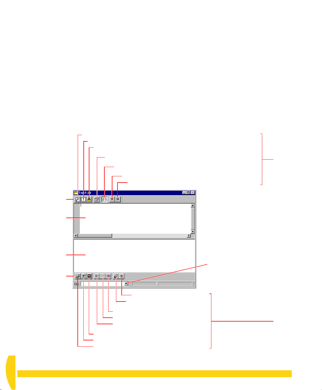
9-7
DELOGGER’S TEXT WINDOW
A DeLogger
screens (Figure 61):
•
Display screen
incoming real-time data and replay data in various
formats
•
Entry screen
with
type commands here and send them to the DT800.
text
(terminal) window contains two
(the upper screen) — displays
(the lower screen) — if you’re familiar
dataTaker
’s native programming language,
Filter incoming data by schedule.
Choose the format of incoming data (replay, text or comma-separated variable).
Capture data to disk as it arrives (as a replay file .dlr).
Open the text window’s Properties dialog box.
Toggle the split screen view on/off.
Clear the display screen.
Pause the flow of incoming data to the display screen.
The Text Menu
When a text window is DeLogger’s front-most window,
the seventh menu on DeLogger’s menu bar is
Figure 20 on page 27). Commands on this menu are
specific to the text window, and some are duplicated
by buttons on the text window’s two toolbars.
Text
(see
Display
screen
buttons
Display screen toolbar
(always available)
Display screen
Entry screen
Site list — assign a Connection
to the text window.
Entry screen toolbar
(available when the
entry screen is active
— click in the entry
screen’s workspace)
Send the program (send all)
Send the highlighted text.
Send the current line.
Save the program (.txt or .cmd).
Load a DeLogger program file (.dlp).
Open an existing command file (.txt or .cmd).
FIGURE 61 A new DeLogger text window
UM-0071-A0
60 Getting Started with DT800
Clear the entry screen.
Turn Command Edit Mode on/off.
Entry
screen
buttons
dataTaker
Page 61
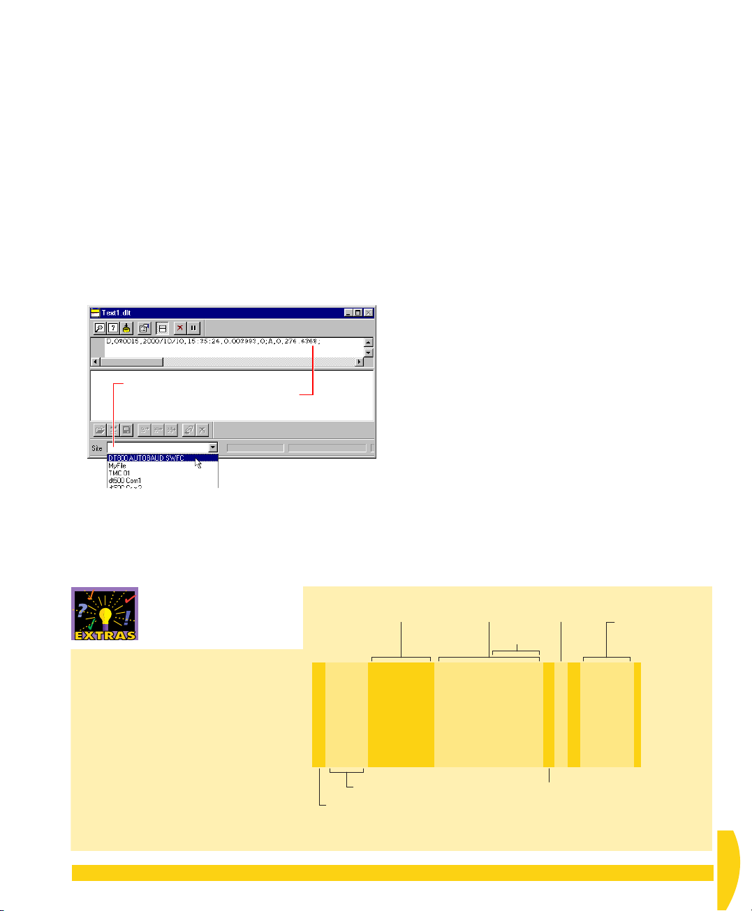
9-8
R
ETURN
D
THE TEXT
INDOW
W
ATA TO
➲ Use DeLogger’s text window to view the
real-time data that the DT800 is returning to
your computer.
To do this…
a) Locate the minimized text window
click its Restore button.
b) In the
Site
drop-down list at the bottom of the text
window, select your DT800’s Connection
(Figure 62).
Select the Connection to your DT800,
then returned data from the DT800
appears in the upper screen.
Text1.dlt
and
A data record appears immediately in the upper
(display) screen of the text window. The right-hand
group of figures in the line is the data returned from
the potentiometer and other channels in your
program (see the “Data Structure — Replay Format”
Extras panel).
c) Carry out the numbered steps in Figure 64 to learn
more about the text window.
FIGURE 62 Assigning the DT800’s Connection to
the text window
Date
of
reading
Data Structure — Replay
Format
Figure 63 shows the main
components of data displayed in
replay format, which is the text
window’s default display format.
CHAPTER 9EXTEND YOUR PROGRAM: Return Data to the Text Window 61
D,080015,2000/05/02,10:08:24,0.007411,0:A,0,13.94076;
D,080015,2000/05/02,10:08:27,0.006801,0:A,0,15.44138;
D,080015,2000/05/02,10:08:30,0.007899,0:A,0,24.52851;
D,080015,2000/05/02,10:08:33,0.008754,0:A,0,27.10516;
D,080015,2000/05/02,10:08:36,0.007411,0:A,0,28.19215;
D,080015,2000/05/02,10:08:39,0.007533,0:A,0,26.95922;
D,080015,2000/05/02,10:08:42,0.008265,0:A,0,25.12281;
D,080015,2000/05/02,10:08:43,0.616821,0:A,0,25.12281;
DT800 serial number
Record type (for example,
D = Returned Data record)
FIGURE 63 Typical default data records (replay format)
Time
of
reading
sub-seconds
Schedule
Time
Record index — depends on record type
(for example,
0 = real-time data)
Readings (only one
shown here)
UM-0071-A0
Page 62
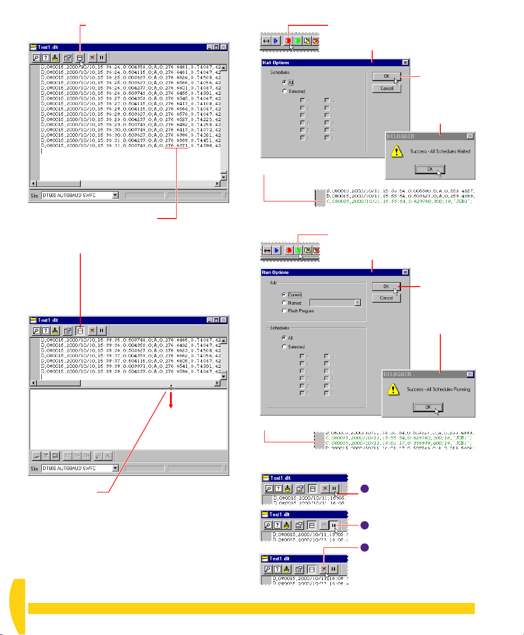
Click the
➊
The display screen fills the text window.
Splitter View Mode
button.
On the main toolbar, click the Halt
➎
button.
The Halt Options dialog box opens.
➏
Click OK in
the dialog
box, then
OK in the
confirmation
box.
Turn the potentiometer’s knob and
➋
watch the resistance value change
in the returned data.
Click the
➌
The text window reverts to its split view:
Splitter View Mode
• The upper screen displays real-time data
as it is returned from the DT800.
• The lower screen is where you can type
commands and send them to the DT800
(if you’re familiar with the
programming language).
button again.
dataTaker
Notice the
➐
marks your Halt command.
The DT800 stops running your schedule and therefore no
data is returned to the text window.
Notice the
➓
change record
On the main toolbar, click the Run
➑
button.
The Run Options dialog box opens.
change record
that
Click OK in
➒
the dialog
box, then
OK in the
confirmation
box.
that marks your Run command.
The DT800 resumes running your schedule and data
continues to be returned to the text window.
Drag the divider to
➍
enlarge the data
display screen.
FIGURE 64 Learn more about the text window
UM-0071-A0
62 Getting Started with DT800
11
Click the
Data ceases to flow into the
text window. (The schedule is
still running in the DT800).
12
Click the
The data flow resumes.
13
Click the
All of the returned data in the
display screen is deleted
(DeLogger’s “return buffer” is
emptied).
Pause
Pause
Clear
button.
button again.
button.
dataTaker
Page 63
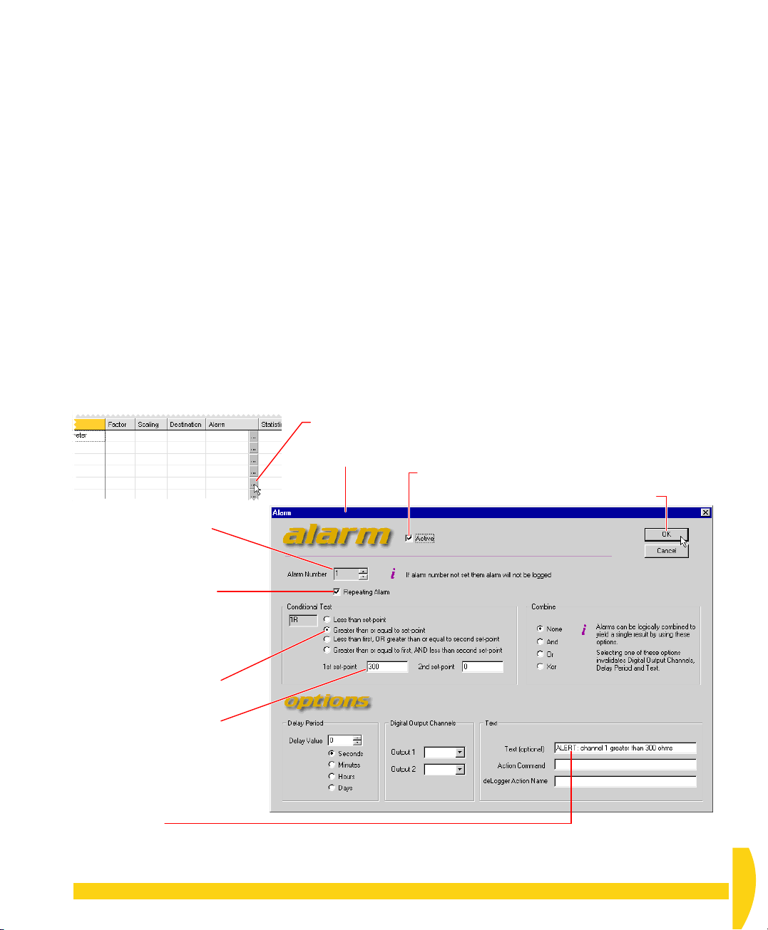
9-9
Here you assign an alarm to the potentiometer
channel.
Because alarm channels don’t generate data, you’ll
make a copy of the potentiometer channel and assign
the alarm to the copy. In this way, the original instance
of the potentiometer channel generates data, and the
copy generates alarms.
ADD AN ALARM
➲ Add an alarm that triggers when the
potentiometer’s resistance is greater than 300
ohms.
To do this…
a) Turn the potentiometer knob fully
(minimum resistance).
b) In the View menu, make sure that
is ticked.
Events
anti
-clockwise
Show Alarm
Click the Configure button in R5’s Alarm column.
➊
The Alarm
dialog box
opens.
This ensures that DeLogger will automatically open
the Event Logs dialog box (Figure 34 on page 36)
when an alarm occurs.
c) Click the text window to make it active. In the Text
menu, choose
then select
In this format, alarms are obvious in the text
window’s display screen.
d) Click the program builder window to make it active.
e) On tab A of the program builder, use the right-
button copy and paste method (see Figure 57 on
page 57) to copy row 1 to row 5.
f) Follow the numbered steps in Figure 65 to specify
the alarm for row 5.
g) In DeLogger’s File menu, choose
h) In the Program menu, choose
Yes
Click
boxes that open.
Tick Active.
➋
Display Screen
Replay format
or OK in any
>
Display Data As…
and click OK.
Save Project
Send to Connection
Warning
or
Click OK.
➐
Attention
.
.
dialog
Set Alarm Number to 1.
➌
Tick Repeating Alarm
➍
to have the DT800 return
an alarm event on every
scan while the alarm
condition exists (not just on
the first alarm scan).
Select the Greater than
➍
or equal to… option.
Type 300 in the 1st set-
➎
point field.
Type an alarm message in
➏
the Text field.
FIGURE 65 Specifying an alarm for channel 1
CHAPTER 9EXTEND YOUR PROGRAM: Add an Alarm 63
UM-0071-A0
Page 64
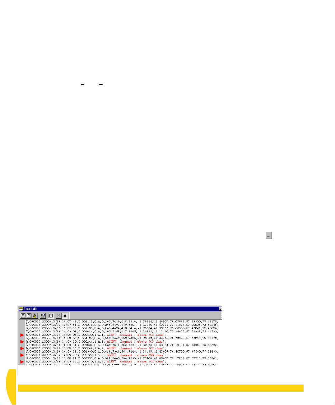
i) Watch the text window and turn the potentiometer
knob to its fully clockwise position.
You’ll see
• alarm records returned to the text window’s
display screen when the potentiometer’s value
exceeds 300 ohms (in addition to the regular
data records); they contain your alarm
message, are marked with a red pointer on the
left-hand side of the display screen, and are
prefixed with
prefixed with
• the Event Logs window open automatically;
each new alarm event appears at the top of the
Alarms tab.
j) Experiment with the potentiometer knob to see the
alarm records returned to the text window and the
Event Logs window.
Alarm messages are also returned to the form
window’s Alarm Message column.
k) When you’re done, close the Event Logs dialog box
if it’s in your way.
A
for alarm (data records are
D
) — Figure 66
9-10
ADD SCHEDULE B
TO THE PROGRAM
Next, you add a second schedule that instructs the
DT800 to scan the potentiometer channel at a faster
rate (in addition to the 5-second rate).
➲ Set schedule B’s rate to 2 seconds, and use
the copy and paste method to add the
potentiometer channel to schedule B.
To do this…
a) At the bottom of the program builder window, click
the tab labelled
You could have used any of tabs B to K.
b) Set a
c) Use the right-button copy and paste method (see
d) On tab B, type
e) On tab B, click the Configure button in the
time interval
seconds by following a similar procedure to that
shown in Figure 29 on page 34.
Figure 57 on page 57) to copy row 1 on tab
paste it into row 1 on tab
The program now instructs the DT800 to scan its
channel 1, the potentiometer channel, every 5
seconds (by schedule A) and every 2 seconds (by
schedule B).
of R1.
Alarm
column of R1. In the Alarm dialog box that
opens:
i. Change the Alarm Number to
ii. Change the value in the set-point field to
iii. Change the alert message to read
channel 1 greater than 425 ohms
iv. Click
B
.
trigger for schedule B of 2
B
.
Potentiometer2s
OK
to close the dialog box.
in the
2
.
Label
ALERT:
.
A
and
column
425
.
FIGURE 66 Alarm and data records returned to DeLogger’s text window — schedule A
UM-0071-A0
64 Getting Started with DT800
dataTaker
Page 65
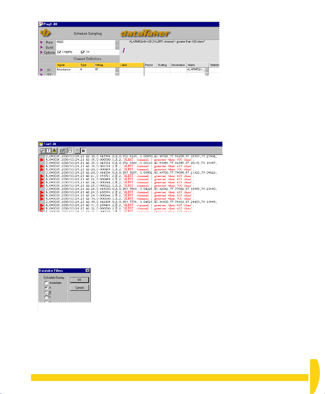
Tab B should now look like Figure 67.
FIGURE 67 Schedule tab B
f) In DeLogger’s File menu, choose
g) In the Program menu, choose
Yes
Click
in any
Warning…
Send to Connection
dialog boxes that open.
Save Project
.
.
h) Experiment with the potentiometer knob to see the
alarm records returned to the text window
(Figure 68) and the Event Logs window.
FIGURE 68 Alarm and data records returned to DeLogger’s text window — schedules A and B
i) In the Text menu, choose
.
Data…
Display Screen
>
Filter
j) In the dialog box that opens (Figure 69), notice that
you can select which schedules’ data is returned to
the text window’s display screen.
FIGURE 69 Schedule filter
k) Click
OK
to close the Filters dialog box.
CHAPTER 9EXTEND YOUR PROGRAM: Add Schedule B to the Program 65
UM-0071-A0
Page 66

CHAPTER 10
O
THER
T
HINGS
Y
OU
C
AN
D
O
WITH
This chapter covers two more important functions of
DeLogger:
• unloading logged data (that is, retrieve data stored
in the DT800’s internal memory) — page 66
• using DeLogger’s spreadsheet window for
manipulating and analysing data — page 68
DEL
OGGER
10-1
UNLOAD LOGGED DATA
Your DT800 has been logging every measurement it
has made since you first sent your program to it
(because Logging was enabled in both of your
schedules). Now you’ll retrieve this data from the
DT800.
By the way: unloading data from the DT800 has
nothing to do with DeLogger’s form, chart, mimic or
text windows — it’s a function that’s available to you
no matter which DeLogger window you’re using.
➲ Unload all of the data currently logged in
your DT800 to a replay file.
To do this…
a) In the
b) Familiarize yourself with the options available in this
c) In the second screen, tick
dataTaker
The first screen (Options) of the unload dialog box
sequence opens (Figure 70).
screen — do NOT make any changes — then click
Next >
.
The second screen (Unload To File) of the unload
dialog box sequence opens (Figure 70).
Replay File
If you upgrade to DeLogger Pro, you’ll have an
additional option here — Unload to Database.
menu, choose
.
Unload…
Unload to File
then select
.
UM-0071-A0
66 Getting Started with DT800
dataTaker
Page 67
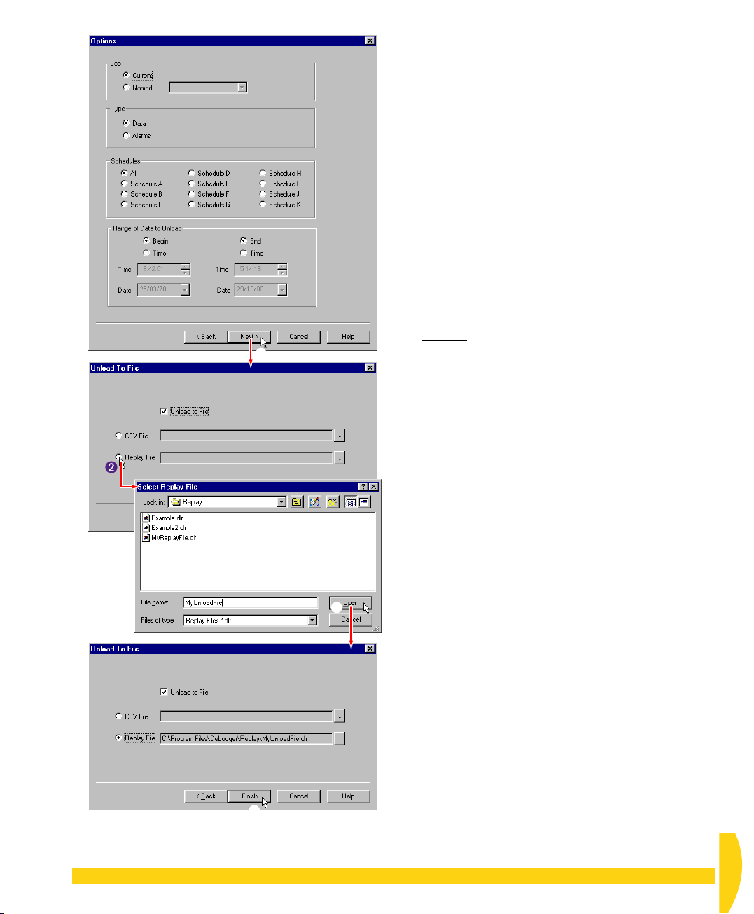
➊
d) In the Select Replay File dialog box that opens:
i. Type
ii. Leave
iii. Click
MyUnloadFile
the
File name
Replay
your file (
Open
(or any name you want) in
field.
as the destination folder for
Save in
).
.
You’re returned to the second unload screen,
which now contains the path to your unload
destination.
e) Back in the second screen, click
A dialog box opens to inform you of the progress of
the unload.
You can use other DeLogger windows during an
unload.
f) While your logged data is unloading, open the
dataTaker
obser
command.
g) If you want to cut the unload short, choose
Unload
finishes.
Because you unloaded your data to the
MyUnloadFile.dlr
DeLogger’s spreadsheet window, and replay it to
DeLogger’s form, chart, text and mimic windows
(see Figure 16 on page 23).
And remember that you could also have unloaded
the logged data to a comma-separated-variable file
(.csv), which you can import into other programs
such as Microsoft Excel.
menu on DeLogger’s menu bar and
ve — don’t choose — the
now. Otherwise, wait until the unload
replay file, you can load it into
Finish
.
Quit Unload
Quit
➌
➍
FIGURE 70 Unload dialog box sequence
CHAPTER 10 OTHER THINGS YOU CAN DO WITH DELOGGER: Unload Logged Data 67
UM-0071-A0
Page 68

10-2
DELOGGER’S SPREADSHEET WINDOW
A DeLogger
spreadsheet into which you can load (“dump”) an
entire DeLogger replay file one row per timestamp,
one column per channel. Then you use standard
spreadsheet tools to manipulate and analyse the data.
You can also
• load the contents of the spreadsheet into Microsoft
Excel (if it’s installed on your computer) with a single
command
• export the contents of the spreadsheet in a variety of
formats.
spreadsheet
Formula bar
window is a standard
The spreadsheet window is different from the form
window in several ways:
• The form window is a dynamic display of incoming
data; the spreadsheet window is a static display of
historical data.
• Each row in the form window displays a variety of
information from one channel; each row in the
spreadsheet window displays just channel readings
from one scan that may include many channels,
each in a separate column.
The Spread Menu
When a spreadsheet window is DeLogger’s front-most
window, the seventh menu on DeLogger’s menu bar is
Spread
(see Figure 20 on page 27). Commands on
this menu are specific to the spreadsheet window, and
some are duplicated by buttons on the spreadsheet
toolbar.
Double-right-click anywhere
in a worksheet to open it in
the Formula One Workbook
Rename a worksheet by
double-clicking its tab
(the Sheet Name dialog
FIGURE 71 A new DeLogger spreadsheet window
UM-0071-A0
68 Getting Started with DT800
box opens).
Spreadsheet toolbar
Set number of decimal places of selected cell(s)
Left, centre, or right align contents of selected cell(s)
Show/hide gridlines
Show/hide row and column headers
Load the current worksheet into Excel (opens Excel).
Set print range
Load a replay file (.dlr).
Scale view down (zoom out)
Scale view up (zoom in)
Designer, where additional
commands are available if
you need them (for example,
Sheet > Insert Sheet, Sheet >
Delete Sheet, Data > Recalc).
dataTaker
Page 69

10-3
LOAD DATA INTO
10-5
WHAT’S NEXT?
A SPREADSHEET
➲ Load a replay file into DeLogger’s
spreadsheet window.
To do this…
a) Locate the minimized spreadsheet window
Spread1.dls
b) In the Spread menu, choose
File…
c) In the Select Replay File dialog box that opens,
highlight
All of the replay file’s data is immediately loaded
into the spreadsheet window.
Notice that each row is one data record (one scan)
and each column contains data from one channel.
10-4
When you’ve finished working with DeLogger, save
the project if you want (DeLogger remembers your
window sizes, locations and so on) then carry out a
software disconnection from the DT800 (
menu >
Or simply quit DeLogger. (You’ll be asked if you want
to save the project, and DeLogger will disconnect
automatically.)
The DT800 continues to operate according to its
current program.
and click its Restore button.
.
Example2.dlr
and click
FINISH OFF
Disconnect…
).
Load Session From
Open
.
Connections
Now that you’ve finished working through this guide,
you’ll have seen how easy the DT800
use and you have enough knowledge to set up your
own basic data acquisition and logging sessions.
So, armed with your
this is just the beginning…
For help or more information, please visit
www. dataTaker.com
representative. Our engineers are always happy to
talk to you.
DT800 dataTaker User’s Manual
or contact your
dataTaker
dataTaker
is to
,
CHAPTER 10 OTHER THINGS YOU CAN DO WITH DELOGGER: Load Data into a Spreadsheet 69
UM-0071-A0
Page 70

Index
Numerics
500/600 series 18
A
acquire data 6, 7
active window
See
front-most window 30
adaptor, mains 10
alarms 7
analog channel 31
, 63
event logs (Extras) 37
B
battery
internal main 10
internal memory-backup 10
, 11
C
changes
See
event logs
channel 24
defined 29
ID 41
label 41
chart window 43
clear
program builder cells 57
clearing the form window (Extras) 42
concepts
Connection 28
data hub 30
data site 28
database 29
replay 30
Connection 19
How Many Connections? (Extras) 28
replay 30
connectors
diagrams (Extras) 12
female 12
male 12
sex (Extras) 12
control panel (replay) 30
copy and paste 57
current window
See
, 55
, 28
front-most window 30
D
data
acquisition 6
hub 30
logging 6
real-time 7
record (Extras) 61
replay 30
site 28
structure (Extras) 61
database 29
date
in returned data (Extras) 61
setting 42
stamp 9
DeLogger Pro (Extras) 18
dialog box
Event Logs 59
Status 21
Unload 67
digital channel 31
DT500/600 series 18
dynamic data view 23
, 7
, 7, 30
, 30
, 64
, 68
E
errors
event logs (Extras) 37
event logs (Extras) 37
Event Logs dialog box 59
Extras
Connections (how many?) 28
connector diagrams 12
connector sex 12
Connectors, Adaptors 12
Data Structure 61
DT800 Host Software 16
Enabling DeLogger Pro 18
Event Logs 37
Flow Control 20
How Many Connections? 28
Re-Installing and Project Compatibility 17
Scan Schedules — DT800 Timetables 33
Sending Commands 8
Switches and Parameters 37
, 64
F
female (connectors) 12
file
replay 30
file Connection (replay) 30
filter (text window) 65
Index 70
UM-0071-A0
Page 71

fixed-format mode 9
flow control (Extras) 20
focus window
See
front-most window 30
form window 38
clearing (Extras) 42
format
defined 11
of returned data 9
fixed-format mode 9
free-format mode 9
Formula One Workbook Designer
form window 38
spreadsheet window 68
free-format mode 9
front-most window (defined) 30
H
hardware flow control 20
heartbeat (LED flash) 14
host computer 11
host software 11
Extras 16
hub
See
data — hub
HWFC 20
, 37, 59
I
ID
channel 41
schedule 41
indicators (LEDs) 14
internal main battery 10
internal memory-backup battery 10
J
jobs
and programs 29
, 11
mimic window 49
P
parameters 37
parameters (Extras) 37
pause command 48
power 10
external 10
internal 10
power-up 11
program builder window 31
programs 24
and jobs 29
project compatibility (Extras) 17
projects 24
purchase DeLogger Pro (Extras) 18
R
reading
in returned data (Extras) 61
real-time data 7
record index
in returned data (Extras) 61
record type
in returned data (Extras) 61
re-installing DeLogger (Extras) 17
replay
Connection 30
control panel 30
defined 30
file 30
site 30
returned data
record structure (Extras) 61
right-click menu 36
RS-232 12
RS-422 12
RS-485 12
, 30
, 57
S
L
label 41, 55
LED indicators 14
logging 6
, 37
, 7, 30
M
main battery 10
mains adaptor 10
male (connectors) 12
memory-backup battery 10
menu
right-click (program builder) 36
: 71
, 11
, 57
scan schedules
See
schedules
schedule
ID 41
in returned data (Extras) 61
schedules 24
DT800 timetables (Extras) 33
SDI-12 12
sending commands (Extras) 8
sensors
defined 11
smart 11
serial channel 12
, 33
, 12
UM-0071-A0
Page 72

serial number
DeLogger 16
default (Extras) 18
DT800
in returned data (Extras) 61
setting the DT800’s date and time 42
site
replay 30
smart sensors
and Serial Channel 12
defined 11
software flow control 20
stamp
date 9
time 9
static data view 23
Status
dialog box 21
SWFC 20
switches (Extras) 37
, 18
, 68
T
terminal window 60
text window 60
filter data 65
time
in returned data (Extras) 61
setting 42
stamp 9
top-level window
See
front-most window 30
transducer (defined) 11
W
window
chart 43
form 38
front-most (defined) 30
mimic 49
program builder 31
terminal 60
text 60
workbook
form window 38
spreadsheet window 68
worksheet
form window 38
spreadsheet window 68
U
unload 67
dialog box 67
upgrade (to DeLogger Pro) 18
, 49
V
version compatibility (Extras) 17
views 23
dynamic 23
static 23
Index 72
, 68
, 68
UM-0071-A0
Page 73
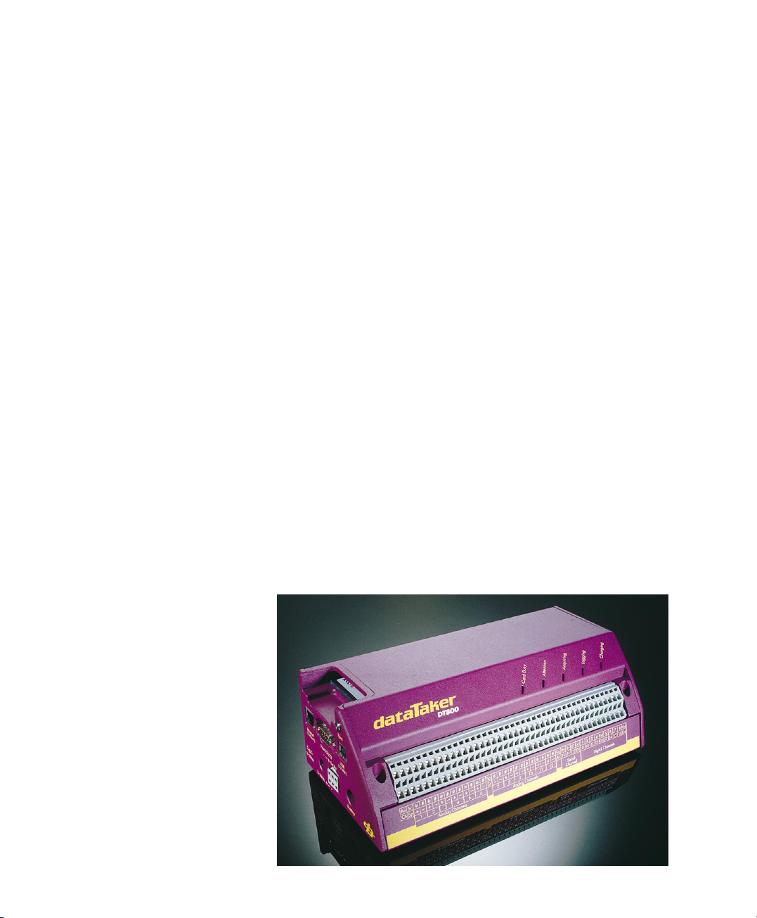
UM-0071-A0
Page 74

UM-0071-A0
 Loading...