

Page 1
XEISDNP
Single Module ISDN Analog Telephone
(POTS) Equipment Interface
Description
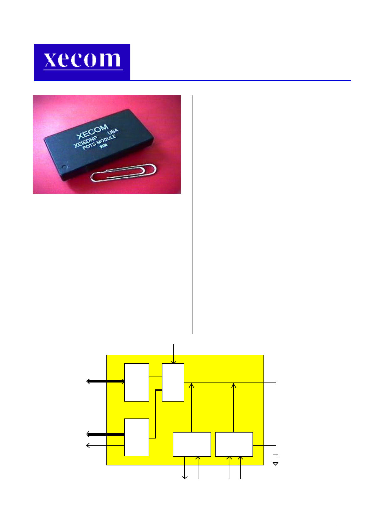
The XEISDNP is a multichip module designed
to interconnect analog telephone equipment such
as a handset, a Group 3 Fax machine, or an
analog modem to an ISDN Terminal Adapter. The
device provides all the functions needed to
support conventional analog subscriber equipment including voice/fax data CODEC, DTMF
tone detector, RING signal generator and telephone line power feed. It provides a simple,
compact solution for designers who wish to integrate an ISDN digital interface into their designs
but also protect their user’s investment in their
existing POTS (Plain Old Telephone Service)
equipment.
The XEISDNP is designed to interface with the
XECOM XEISDNU Single Module ISDN Terminal
Adapter.
Features
• Small size: 2.75" x 1.38" x 0.42"
• Adds POTS function to XECOM XEISDNU
• Supports standard analog telephones, Group 3
FAX machines, and analog modems
• Provides all Central Office functions to analog
telephone equipment
• Uses GCI (IOM-2) or IDL standard communication bus to exchange voice/fax/data between
its on board CODEC and ISDN Terminal
Adapter
• Pin configurable to Mu-law or A-law PCM
coding
• Programmable for B1 or B2 channel of the
ISDN Basic Rate interface
• Uses standard data bus to access DTMF
codes from the ISDN TA
• Built-in 150V DC inverter to support RING
signal generation
• Built in power supply provides the telephone
handset with 30 to 50 mA current
RING GeneratorDC Power supply
10uF/250V
+
To telephone set
or FAX machine
CODEC
Voice/FAX
for
Data
DTMF
Decoder
GCI or IDL Bus
Three state
DTMF ready
DTMF output
Off Hook Power CTRL RING CTRL
Voice/FAX/Modem signal path (Analog)
ROUTE
SWITCH
Route CTRL
Page 2
Page 2 XEISDNP
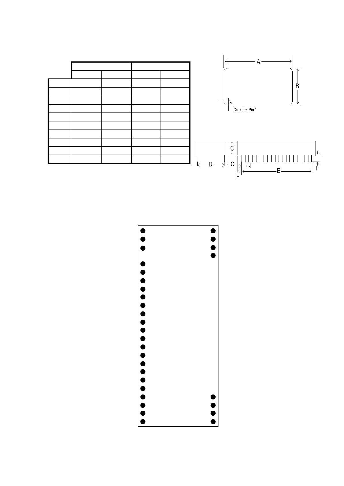
Mechanical Specifications
INCHES METRIC (MM)
MIN MAX MIN MAX
A
2.740 2.760 69.60 70.10
B
1.370 1.390 34.80 35.31
C
0.420 0.430 10.67 10.92
D
1.190 1.210 30.23 30.73
E
2.290 2.310 58.17 58.67
F
0.125 0.200 3.18 5.08
G
0.080 0.100 2.03 2.54
H
0.215 0.235 5.46 5.97
I
0.090 0.110 2.29 2.79
J
0.020 0.025 0.51 0.64
(Total pin count is 24 per side view.)
Pin Configuration
(Blank pin location indicates no pin installed)
TTIP
RING
DC_OUT
NC
DR/RXDIN
DT/TXD1
FST/CD1N
FSR/TXD3
NC
NC
OH
DTMF_RDY
RING_EN
RING_DC
PWR_CTRL
ROUTE_CT
/PDI/DREQ
D4
D5
D6
D7
-12V
GND
++5V
GND
B_M_CLK/RCLK
GND
GND
Mu/A
NC
+12V
1
2
3
4
5
6
7
8
9
10
11
12
13
14
15
16
17
18
19
20
21
22
23
24
48
47
46
45
44
43
42
41
40
39
38
37
36
35
34
33
32
31
30
29
28
27
26
25
Page 3

XEISDNP Page 3
Pin Descriptions
Name Pin # Direction Description
TIP 1 I/O Connect to POTS equipment
RING 2 I/O Connect to POTS equipment
DC_OUT 3 Output Test pin for the 150V DC supply for RING signal. Bypass to GND
with 10uF/250V capacitor.
NP 4, 29-44 No pin installed
NC 5,10,11,26 No connection allowed
DR/RXDIN 6 Input Data Receive for IDL or GCI
DT/TXD1 7 Output Data Transmit for IDL or GCI
FST/CDIN 8 Input Frame Synchronize Transmission: This pin accepts an 8KHz
clock that synchronizes the output of the serial PCM data at the
DT pin.
FSR/TXD3
(B2/B1)
9 Input When an ISDN mode (IDL or GCI) has been selected with
BCLKR, this pin selects either B1 (logic 0) or B2 (logic 1) as the
active data channel.
NC 10,11 No connection allowed
OH 12 Output On/Off hook status of POTS equipment
DTMF_RDY 13 Output Signal to inform controller a DTMF tone has been detected
RING_EN 14 Input Control to cycle on and off theRING voltage when DC_EN is
active.
DC_EN 15 Input Control signal to enable 150 VDC generation for RING signal.
This pin should be held high from before the first RING ENable
until the phone set goes off hook or the caller hangs up.
PWR_CTRL 16 Input Control signal for powering up POTS telephone set.
ROUTE_CTRL 17 Input Control pin for voice signal switching inside the module.
/PDI 18 Input Power down mode control.
D4 - D7 19-22 Output Connect to controller main data bus low byte, lines D4 - D7;
carries DTMF code.
-12V 23 -12V DC power supply
GND 24,28,45,47 Ground
+12V 25 +12V DC power supply
Mu/A 27 Input Connect to logic 1 (+5V) selects A law and logic 0 (GND) selects
Mu law
B_M_CLK
/RCLK
(IDL/GCI)
46 When this pin is held at a logic 1, FST, BCLKT, DT and DR
become IDL mode. When this pin is held at a logic 0, FST,
BCLKT, DT and DR become GCI mode.
VCC 48 +5V DC power supply
Page 4

Page 4 XEISDNP
Electrical Specifications
ABSOLUTE MAXIMUM RATINGS
Parameter Maximum Value*
Supply Voltage VCC (+5V) +6.5 Volts
Supply Voltage VDD (+12V) +15 Volts
Supply Voltage VEE (-12V) -15 Volts
DC input voltage (TTL inputs) -0.6 Volts to +6.5 Volts
Storage Temperature Range -25C to +85C
Lead Temperature (soldering, 2 sec/wave) +260C
Operating Temperature Range 0 to 70C
*Exceeding these values may result in permanent damage to the device
POWER SUPPLY CHARACTERISTICS (Ta = +70C)
Symbol Parameter Min Typ Max Unit Notes
VCC Supply Voltage 4.75 5.0 5.25 Volts
ICC VCC Supply Current 10 mA
VDD Supply Voltage +9 +12 +15 Volts
IDD VDD Supply Current 100 mA
VEE Supply Voltage -9 -12 -15 Volts
IEE VEE Supply Current 20 mA
I/O Characteristics
ANALOG TELEPHONE PORT (POTS) SPECIFICATIONS
DC Supply
20 - 24 Volts nominal
Ring Voltage
60 VAC nominal
Voice Transmission
Frequency range: 300–3000 Hz
Impedance: 600 ohms (nominal)
Signals Provided
Supervisory: dial tone, busy tone & ringback
Signals Decoded
Dialing: DTMF and dial pulse
Page 5

XEISDNP Page 5
Application Circuit
Page 6

Page 6 XEISDNP
Central Office Function
The XEISDNP Analog Phone Line Adapter provides an interface between an ISDN Terminal
Adapter data channel and an analog (POTS) telephone. In an analog (Plain Old Telephone Service)
system the Central Office (CO) of the telephone company supplies a customer telephone with DC
power when the subscriber handset is removed from the hook (off-hook) and delivers calling progress
tones, like Dial tone, Ring-back signal and Busy signal when the phone is in use. In addition, when a
call arrives while the handset is on-hook, the CO sends an AC signal to ring the phone set. The CO
detects and digitizes the key tones or dial pulses and the subscriber’s voice signals for transmission
through the network.
ISDN provides a pure digital service to the subscriber, with no provision for line power or analog
signaling tones. Therefore to use analog equipment with ISDN service these functions must be
provided locally. The XEISDNP is designed to duplicate the analog user front end (line card) of a
Central Office switch. The following list summarizes the CO functions which the Adapter must replace:
• Sending ring signal to an on-hook phone when its number is called.
• Sending supply power to the telephone set when it is off-hook.
• Sending calling progress tones, including dial tone, busy signal and ring-back tone.
• Detecting and encoding the tones generated when the user “dials” a number.
• Coding the local users voice signal for the digital system and decoding the incoming digitized voice
data to an analog signal for the local hand-set.
Adapter Functional Blocks
CODEC
The CODEC inside the XEISDNP converts the voice signal from the telephone handset to a digital
data stream and sends it to the ISDN Terminal Adapter. From the other direction it receives the
processed B channel bit stream from the Terminal Adapter, converts it to analog voice signal, then
sends it to the telephone handset. The coding/decoding scheme may be changed from A-law to Mulaw by switching the pin 27 Mu/A setting. The communication between the CODEC and the ISDN
controller uses either GCI( also known as IOM-2) or IDL standard depending on the logic level of pin
46. The data channel can be set for B1 or B2 of the ISDN line by the logic state of pin 9.
DTMF Decoder
The “touch tone” keys on a phone set generate Dual Tone Multi-Frequency (DTMF) tones. In a
POTS system, the DTMF tones are detected by the central office system, but in ISDN service, the
Terminal Adapter provides this function. The decoding inside the XEISDNP module converts the tones
to a digital signal the main ISDN controller (XEISDNU, for example) can read. It also generates a
DTMF_RDY signal to inform the controller a DTMF tone has been detected. The main controller then
issues a DTMF_EN signal to enable the DTMF code output to the system data bus. The four-bit DTMF
code is placed in the low byte of the data bus in the high nibble of the byte (D4 - D7).
Ring Signal Generation
An analog phone requires a 60_90VAC ring signal, so a voltage inverter has been designed inside
the module to convert the +12 volt power input into a high voltage ring supply output. Pin 3 is for
testing this voltage and should be bypassed to ground with a 10uF/250V capacitor. When DC_EN (pin
15) is pulled high by the TA Module, DC_OUT (pin 3) should have a 150_170 VDC output. The input
signal to control the ring active period is RING_EN (pin 14), which can be controlled by the TA Module
to cycle the ring signal (pin 2) in a pattern of two-seconds active or four-seconds active. (See Figure 1
on page 7)
Page 7

XEISDNP Page 7
Figure 1. Ring signal control sequence and Timing
Handset Power
Whenever the phone set connected to the POTS module is off-hook, the module will feed the phone
set with a DC current, normally in the range of 30 to 50 MA. At the same time it sends an off-hook
signal through the OH pin (12) and keeps it high until the local phone set hangs up.
Configuration and Setup
When the XEISDNP is used with the XEISDNU Terminal Adapter in the recommended application
circuit, all setup and configuration is controlled by the Terminal Adapter.
DC_EN
RING_EN
RING_DC
5VDC
5VDC
150VDC
60-90VAC
RING
Page 8

Page 8 XEISDNP
Terms of Sale
Devices sold by XECOM are covered by the warranty provisions appearing in its Terms of Sale
only. XECOM makes no warranty, express, statutory, implied, or by description regarding the
information set forth herein, or regarding the freedom of the described devices from patent
infringement. XECOM makes no warranty of merchantability or fitness for any purposes. XECOM
reserves the right to discontinue production and change specifications and prices at any time and
without notice. This product is intended for use in normal commercial applications. Applications
requiring extended temperature range, unusual environmental requirements, or high reliability
applications, such as military, medical life-support or life-sustaining equipment, are specifically not
recommended without additional processing and authorization by XECOM for such application.
Life Support Policy
XECOM assumes no responsibility for the use of any circuitry other than circuitry embodied in a
XECOM product. No other circuits, patents, or licenses are implied. XECOM’s products are not
authorized for use as Critical Components in Life Support Devices or Systems.
Life Support Devices or Systems are devices or systems which, (a) are intended for surgical
implant into the body, or (b) support or sustain life, and whose failure to perform, when properly
used in accordance with instructions provided in the labeling, can be reasonably expected to result
in significant injury to the user.
A Critical Component is any component of a life support device or system whose failure to perform
can be reasonably expected to cause failure of the life support device or system, or to affect its
safety or effectiveness.
Copyright, XECOM © 1997
While Xecom, Inc. has made every effort to ensure that the information presented here is accurate,
XECOM will not be liable for any damages arising from errors or omission of fact. XECOM reserves
the right to modify specifications and/or prices without notice. Products mentioned herein are used for
identification purposes only and may be trademarks and/or registered trademarks of their respective
companies.
Xecom, Inc.
374 Turquoise Street
Milpitas, CA 95035 USA
Tel: 408 • 945 • 6640
Fax: 408 • 942 • 1346
www.xecom.com
#9708-XEISDNP
 Loading...