

Page 1

ELECTRICAL
Revision: 2007 April
2008 FX35/FX45
A
B
SECTION WW
CONTENTS
SERVICE INFORMATION ............................3
PRECAUTION .....................................................3
Precaution for Supplemental Restraint System
(SRS) "AIR BAG" and "SEAT BELT PRE-TEN-
SIONER" ...................................................................
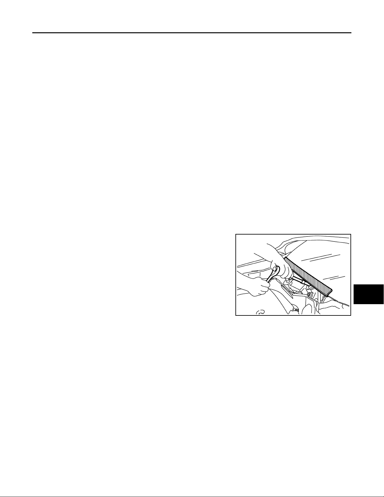
Precaution for Procedure without Cowl Top Cover ......3
FRONT WIPER AND WASHER SYSTEM ..........4
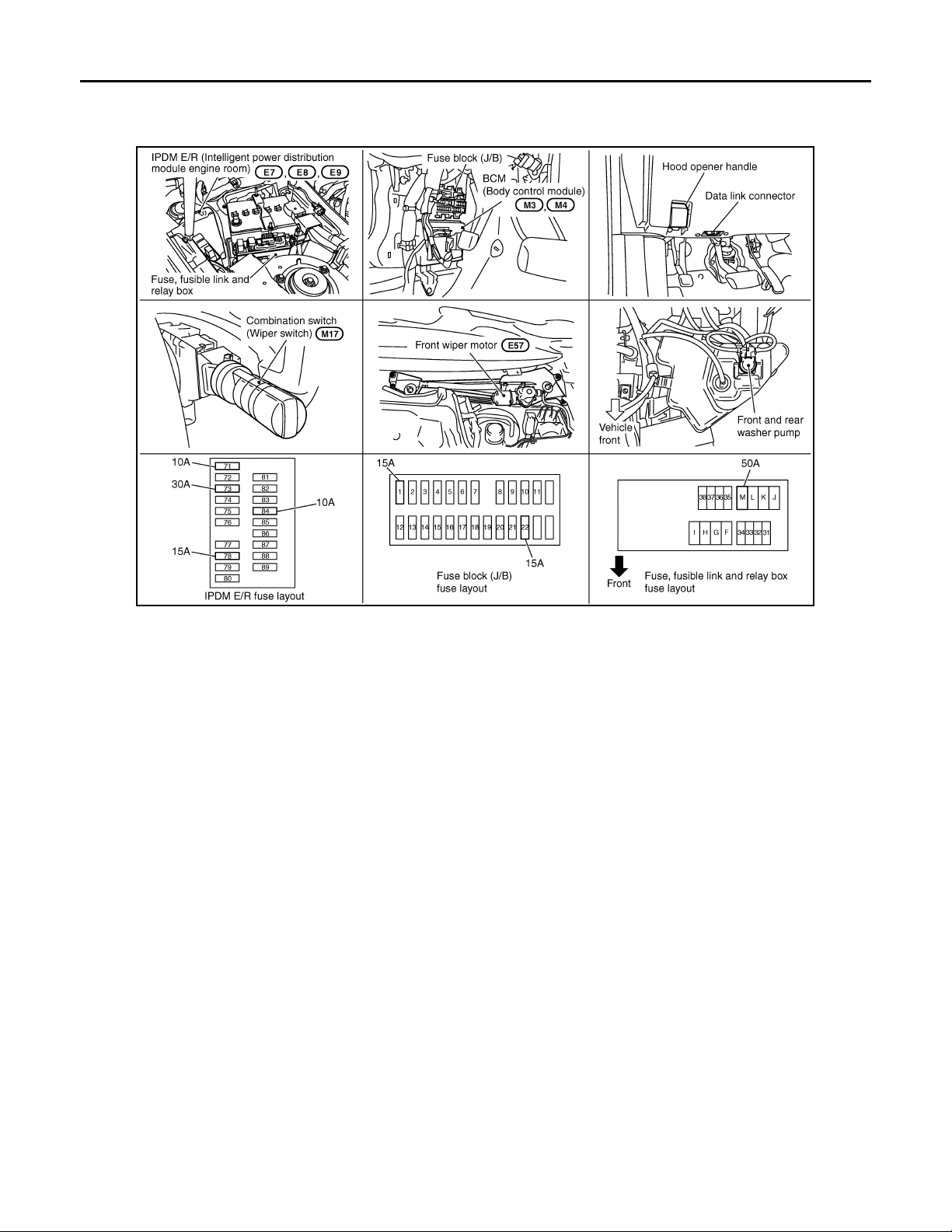
Component Parts and Harness Connector Loca-
tion ............................................................................
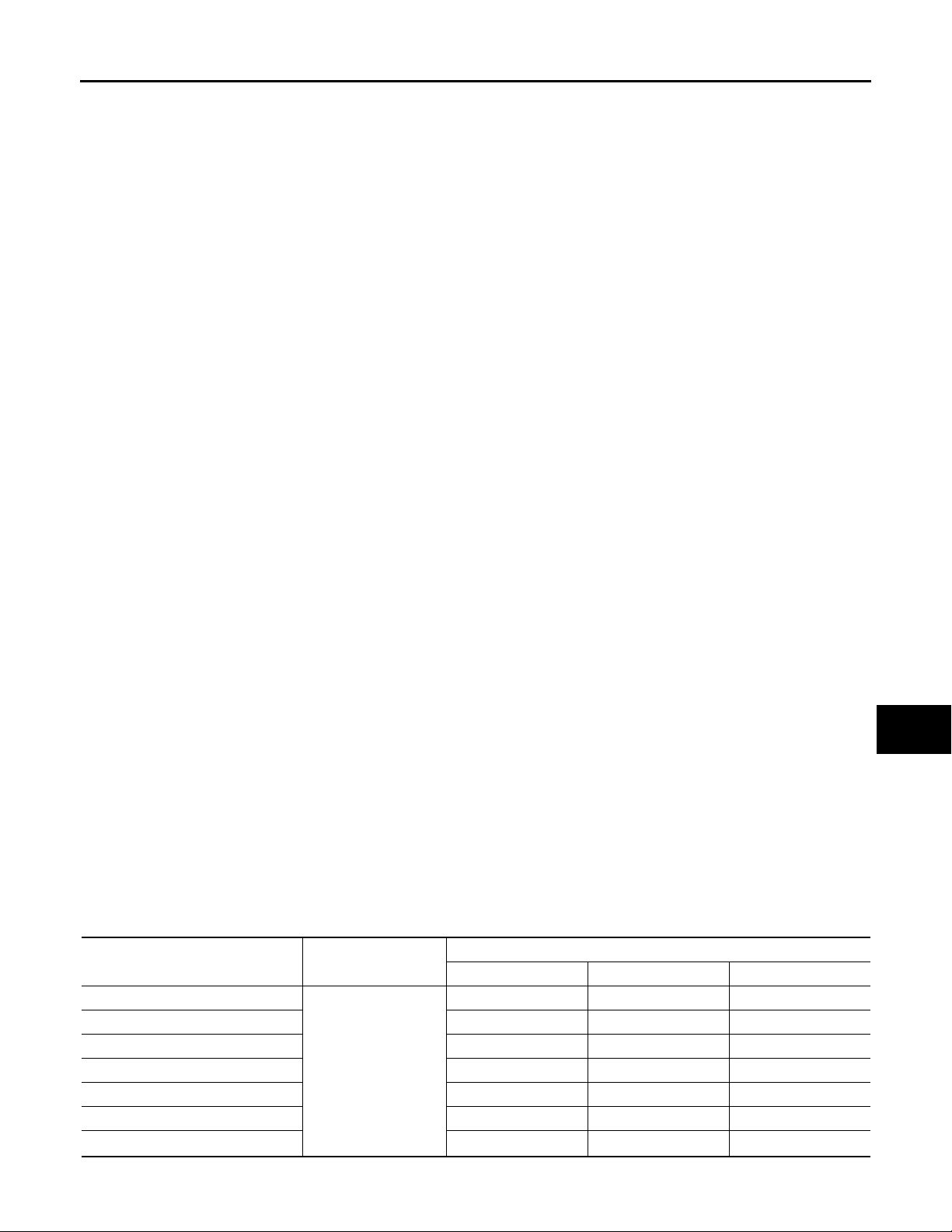
System Description ...................................................4
CAN Communication System Description .................6
CAN Communication Unit .........................................7
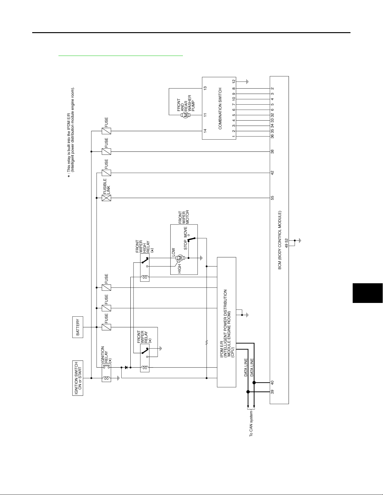
Schematic .................................................................7
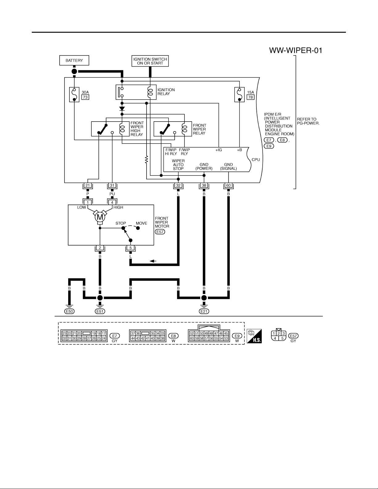
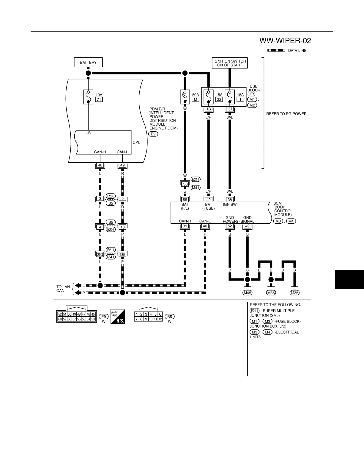
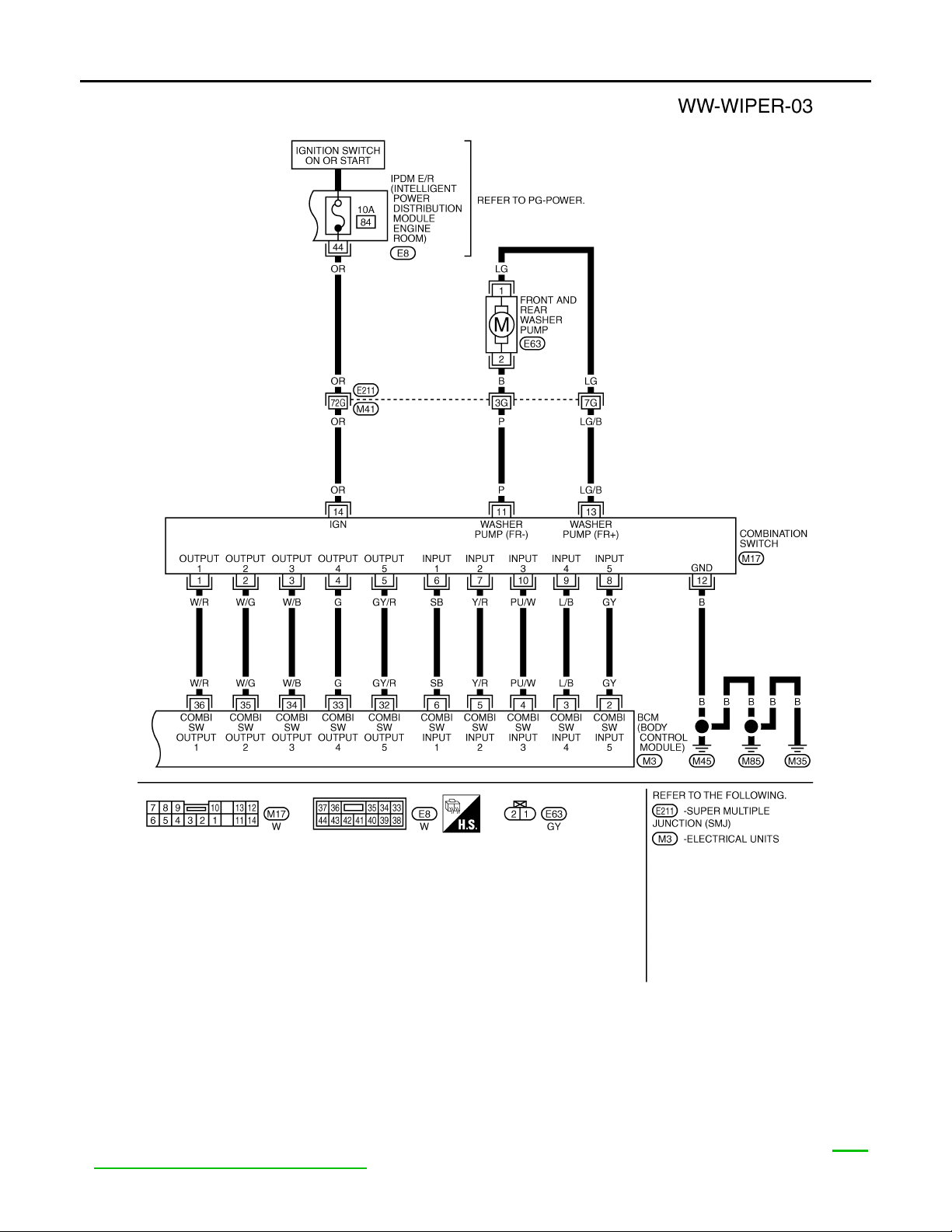
Wiring Diagram - WIPER - ........................................8
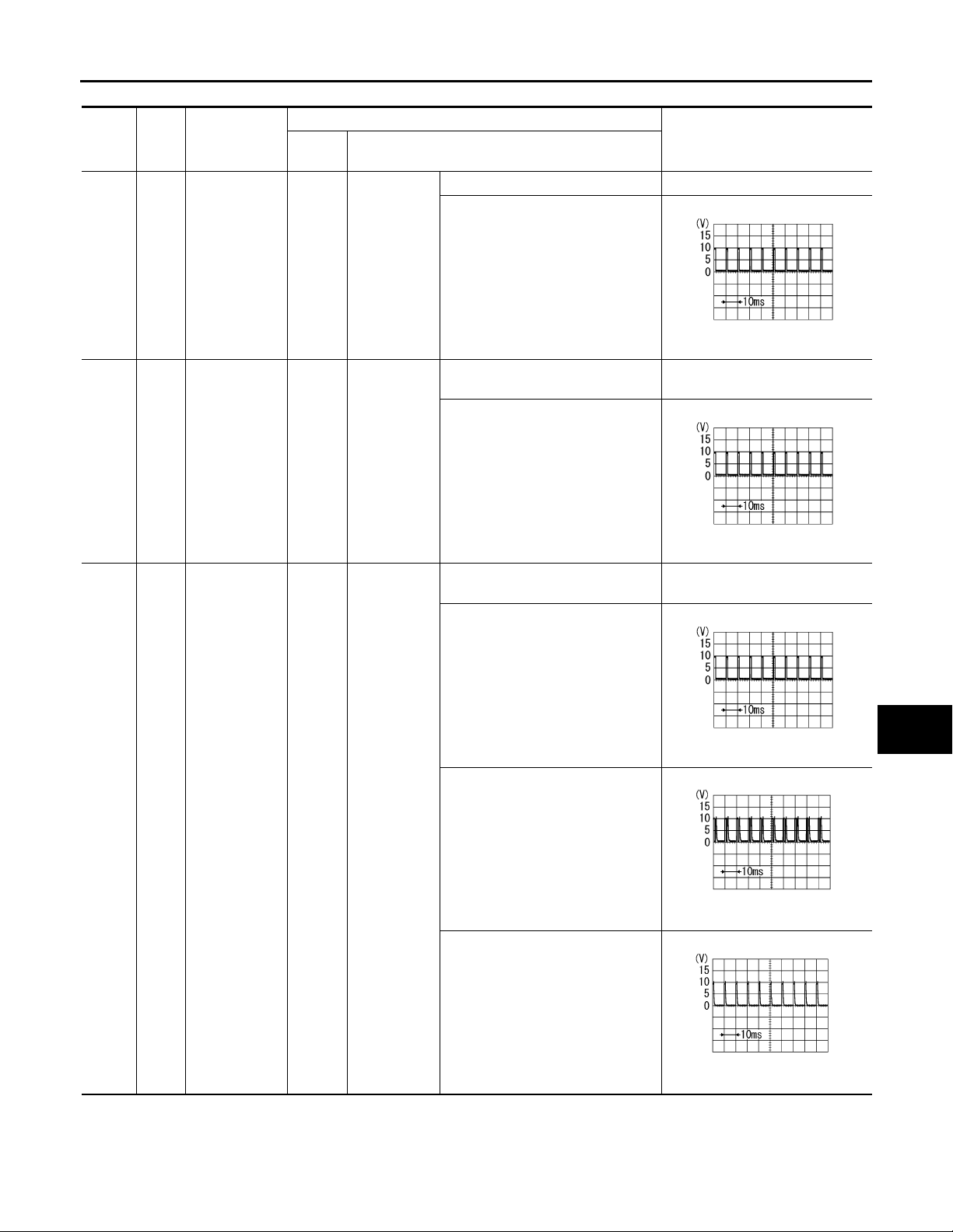
Terminal and Reference Value for BCM .................10
Terminal and Reference Value for IPDM E/R .........14
How to Proceed with Trouble Diagnosis .................14
Preliminary Check ...................................................14
CONSULT-III Functions (BCM) ...............................15
CONSULT-III Functions (IPDM E/R) .......................16
Front Wiper Does Not Operate ................. ... .... .......17
Front Wiper Does Not Return to Stop Position .......18
Only Front Wiper Low Does Not Operate ...............19
Only Front Wiper High Does Not Operate ...............20
Only Front Wiper Intermittent Does Not Operate ....21
Front Wiper Interval Time Is Not Control led by Ve-
hicle Speed .............................................................
Front Wiper Intermittent Operation Switch Posi-
tion Cannot Be Adjusted .........................................
Wiper Does Not Wipe When Front Washer Oper-
ates .........................................................................
After Front Wiper Operate for 10 Seconds, They
Stop for 20 Seconds, and After Repeating the Op-
eration Five Times, They Become Inoperative ........
Front Wiper Does Not Stop .....................................23
Removal and Installation of Front Wiper Arms, Ad-
justment of Wiper Arms Stop Location ....................
Removal and Installation of Front Wiper Drive As-
sembly ............................. ........................................
21
22
22
22
23
24
WIPER, W ASHER & HORN
Disassembly and Assembly of Front Wiper Drive
Assembly ............................ .....................................
Washer Nozzle Adjustment ....................... ... ... ... .....25
Washer Tube Layout .......................... ... .... ... ...........27
Removal and Installation of Front Washer Nozzle ....27
3
4
Removal and Installation of Front Washer Tube
Joint ................................. ........................................
Inspection of Washer Nozzle ...................................27
Inspection of Front Wiper and Washer Switch Cir-
cuit ................................... ........................................
Removal and Installation of Front Wiper and
Washer Switch ....................... ..................................
Removal and Installation of Washer Tank ...............28
Removal and Installation of Front and Rear Wash-
er Pump ...................................................................
REAR WIPER AND WASHER SYSTEM ..........30
Component Parts and Harness Connector Loca-
tion ................................ ................................... ........
System Description ..................................................30
Wiring Diagram - WIP/ R - .......................................32
Terminal and Reference Value for BCM .... ... ... ... .....33
How to Proceed with Trouble Diagnosis ..................35
Preliminary Check . ....................................... ... ... .....36
CONSULT-III Functions (BCM) ...............................36
Rear Wiper Does Not Operate ................................37
Rear Wiper Does Not Return to Stop Position ........39
Only Rear Wiper ON Does Not Operate ..................40
Only Rear Wiper INT Does Not Operate .................40
Wiper Does Not Wipe When Rear Washer Oper-
ates .................................. ................................... .....
Rear Wipers Do Not Stop ........................................40
Removal and Installation of Rear Wiper Arm, Ad-
justment of Wiper Arms Stop Location ....................
Removal and Installation of Rear Wiper Blade ........41
Removal and Installation of Rear Wiper Motor ........42
Washer Nozzle Adjustment ....................... ... ... ... .....43
Washer Tube Layout .......................... ... .... ... ...........43
Removal and Installation of Washer Nozzle ............43
Check Valve ............................................................44
25
27
28
28
29
30
40
40
C
D
E
F
G
H
I
J
WW
L
M
N
O
P
WW-1
Page 2

Inspection of Front Wiper and Washer Switch Cir-
Revision: 2007 April
2008 FX35/FX45
cuit ..........................................................................
Removal and Installation of Rear Wiper and
Washer Switch ........................................................
Removal and Installation of Washer Tank ..............44
Removal and Installation of Front and Rear Wash-
er pump ..................................................................
44
44
44
Removal and Installation of Front Power Socket -
1 .................................... ..........................................
Removal and Installation of Front Power Socket -
2 .................................... ..........................................
Removal and Installation of Rear Power Socket .....46
Removal and Installation of Luggage Room Power
Socket .....................................................................
45
46
46
POWER SOCKET .............................................. 45
Wiring Diagram - P/SCKT - .................................... 45
HORN ................................................................. 48
Wiring Diagram - HORN - .......................................48
Removal and Installation .. ... ... .... ... ..........................48
WW-2
Page 3
< SERVICE INFORMATION >
Revision: 2007 April
2008 FX35/FX45
PRECAUTION
SERVICE INFORMATION
PRECAUTION
Precaution for Supplemental Restraint System (SRS) "AIR BAG" and "SEAT BELT PRE-TENSIONER"
The Supplemental Restraint System such as “AIR BAG” and “SEAT BELT PRE-TENSIONER”, used along
with a front seat belt, helps to reduce the risk or severity of injury to the driver and front passenger for certain
types of collision. This system includes seat belt switch inputs and dual stage front air bag modules. The SRS
system uses the seat belt switches to determine the front air bag deployment, and may only deploy one front
air bag, depending on the severity of a collision and whether the front occupants are belted or unbelted.
Information necessary to service the system safely is included in the “SUPPLEMENTA L RESTRAINT SYSTEM” and “SEAT BELTS” of this Service Manual.
WARNING:
• To avoid rendering the SRS inoperative, which could increase the risk of personal injury or death in
the event of a collision which would result in air bag inflation, all maintenance must be performed by
an authorized NISSAN/INFINITI dealer.
• Improper maintenance, including incorrect removal and installation of the SRS, can lead to personal
injury caused by unintentional activation of the system. For removal of Spiral Cable and Air Bag
Module, see the “SUPPLEMENTAL RESTRAINT SYSTEM”.
• Do not use electrical test equipment on any circuit related to the SRS unless instructed to in this
Service Manual. SRS wiring harnesses can be identified by yellow and/or orange harnesses or harness connectors.
Precaution for Procedure without Cowl Top Cover INFOID:0000000001612917
INFOID:0000000001612916
A
B
C
D
E
F
G
H
When performing the procedure after removing cowl top cover , cover
the lower end of windshield with urethane, etc.
I
J
WW
PIIB3706J
L
M
N
O
P
WW-3
Page 4
FRONT WIPER AND WASHER SYSTEM
Revision: 2007 April
2008 FX35/FX45
< SERVICE INFORMATION >
FRONT WIPER AND WASHER SYSTEM
Component Parts and Harness Connector Location INFOID:0000000001328542
PKIC9701E
System Description INFOID:0000000001328543
• All front wiper relays (HI, LO) are included in IPDM E/R (intelligent power distribution module engine room).
• Wiper switch (combination switch) is composed of a combination of 5 output terminals and 5 input terminals.
Terminal combination status is read by BCM (body control module) when switch is turned ON.
• BCM controls front wiper LO, HI, and INT (intermittent) operation.
• IPDM E/R operates wiper motor according to CAN communication signals from BCM.
OUT LINE
Power is supplied at all times
• through 50 A fusible link (letter M, located in fuse, fusible link and relay box.)
• to BCM terminal 55,
• through 15 A fuse [No. 22, located in fuse block (J/B)]
• to BCM terminal 42,
• through 30 A fuse (No. 73, located in IPDM E/R)
• to front wiper relay, located in IPDM E/R,
• through 15 A fuse (No. 78, located in IPDM E/R) and
• through 10 A fuse (No. 71, located in IPDM E/R)
• to CPU located in IPDM E/R.
When the ignition switch is ON or START position, power is supplied
• to ignition relay located in IPDM E/R, from battery direct,
• through 15 A fuse [No. 1, located in fuse block (J/B)]
• to BCM terminal 38,
• through ignition relay, located in IPDM E/R
• to front wiper relay, located in IPDM E/R
• to front wiper high relay, located in IPDM E/R and
• to CPU located in IPDM E/R,
• through 10 A fuse (No. 84, located in IPDM E/R)
• through IPDM E/R terminal 44
• to combination switch terminal 14.
Ground is supplied
WW-4
Page 5
FRONT WIPER AND WASHER SYSTEM
Revision: 2007 April
2008 FX35/FX45
< SERVICE INFORMATION >
• to BCM terminals 49 and 52
• through grounds M35, M45 and M85,
• to IPDM E/R terminals 38 and 60
• through grounds E21, E50 and E51,
• to combination switch terminal 12
• through grounds M35, M45 and M85.
LOW SPEED WIPER OPERATION
When wiper switch is in LOW position, BCM detects low speed wiper ON signal by BCM wiper switch reading
function.
BCM sends front wiper request signal (LO) through CAN communication
• from BCM terminals 39 and 40
• to IPDM E/R terminals 48 and 49.
When IPDM E/R receives front wiper request signal (LO), it turns ON front wiper relay located in IPDM E/R,
power is supplied
• through front wiper relay
• through front wiper high relay
• through IPDM E/R terminal 21
• to front wiper motor terminal 1.
Ground is supplied
• to front wiper motor terminal 2
• through grounds E21, E50 and E51.
With power and ground supplied, the front wiper motor operates at low speed.
HIGH SPEED WIPER OPERATION
When wiper switch is in HI position, BCM detects high speed wiper ON signal by BCM wiper switch reading
function.
BCM sends front wiper request signal (HI) through CAN communication
• from BCM terminals 39 and 40
• to IPDM E/R terminals 48 and 49.
When IPDM E/R receives front wiper request signal (HI), it turns ON front wiper relay (located in IPDM E/R),
power is supplied
• through front wiper relay
• through front wiper high relay
• through IPDM E/R terminal 31
• to front wiper motor terminal 4.
Ground is supplied
• to front wiper motor terminal 2
• through grounds E21, E50 and E51.
With power and ground supplied, the front wiper motor operates at high speed.
INTERMITTENT OPERATION
Front wiper intermittent operation delay interval is determined from a combination of 3 switches (intermittent
operation dial position 1, 2, and 3) and vehicle speed signal.
Speed dependent wiper controlled mode can be changed by the function setting of CONSULT-III or display.
During each intermittent operation delay interval, BCM sends front wiper request signal to IPDM E/R.
A
B
C
D
E
F
G
H
I
J
WW
L
M
Wiper Dial Position Setting
Wiper intermittent dial position
Example: For wiper intermittent dial position 1
N
Intermittent operation
interval
1Short
2ONONOFF
3ONOFFOFF
4 OFF OFF OFF
5OFFOFFON
6OFFONON
7 OFF ON OFF
↑
↓
Long
INT VOLUME 1 INT VOLUME 2 INT VOLUME 3
ON ON ON
Combination switch
O
P
WW-5
Page 6

FRONT WIPER AND WASHER SYSTEM
Revision: 2007 April
2008 FX35/FX45
< SERVICE INFORMATION >
Using combination switch reading function, BCM detects ON/OFF status of INT VOLUME 1, 2, and 3.
When combination switch status is as listed below, BCM determines that it is wiper intermittent dial position 1.
• INT VOLUME 1: ON (Continuity exists between combination switch output 3 and input 1.)
• INT VOLUME 2: ON (Continuity exists between combination switch output 5 and input 1.)
• INT VOLUME 3: ON (Continuity exists between combination switch output 4 and input 2.)
BCM determines front wiper intermittent operation delay interval from wiper intermittent dial position 1 and
vehicle speed, and sends wiper request signal (INT) to IPDM E/R.
AUTO STOP OPERATION
With wiper switch turned OFF, wiper motor will continue to operate until wiper arms reach windshield base.
When wiper arms are not located at base of windshield with wiper switch OFF, ground is provided
• from IPDM E/R terminal 21
• to front wiper motor terminal 1, in order to continue wiper motor operation at low speed.
When wiper arms reach base of windshield, front wiper motor terminals 5 and 2 are connected,
and Ground is supplied
• to IPDM E/R terminal 32
• through front wiper motor terminals 5 and 2
• through grounds E21, E50 and E51.
Then the IPDM E/R sends auto stop operation signal to BCM through CAN communication.
When the BCM receives auto-stop operation signal, BCM sends wiper stop signal to IPDM E/R through CAN
communication.
IPDM E/R stops wiper motor . Wiper motor will then stop wiper arms at the STOP position.
WASHER OPERATION
When wiper switch is in front wiper washer position with ignition switch on, BCM detects front wiper switch is
on the washer position by BCM wiper switch reading function (Refer to "COMBINATION SWITCH READING
FUNCTION"), combination switch (wiper switch) ground is supplied
• to combination switch terminal 13
• through front and rear washer pump terminal 1
• to front and rear washer pump terminal 2
• through combination switch terminal 11
• to combination switch terminal 12
• through grounds M35, M45 and M85.
With ground supplied, front and rear washer pump is operated.
When BCM detects that front and rear washer pump has operated for 0.4 seconds or linger, BCM operates
front wiper motor for low speed.
When BCM detects washer switch is OFF, low speed operation cycles approximately 2 times and stops.
MIST OPERATION
When wiper switch is turned to MIST position, wiper low speed operation cycles once and then stops.
For additional information about wiper operation under this condition, Refer to "LOW SPEED WIPER OPERATION".
If switch is held in MIST position, low speed operation continues.
FAIL-SAFE FUNCTION
If an abnormality occurs in CAN communications, IPDM E/R holds the condition just before fail-safe status is
initiated until ignition switch is turned OFF. (If wipers were operating in LO just before the initiation of fail-safe
status, they continue to operate in LO until ignition switch is turned OFF.)
COMBINATION SWITCH READING FUNCTION
Refer to BCS-4, "System Description".
CAN Communication System Description INFOID:0000000001328544
CAN (Controller Area Network) is a serial communication line for real time application. It is an on-board multiplex communication line with high data communication speed and excellent error detection ability. Many electronic control units are equipped onto a vehicle, and each control unit shares information and links with other
control units during operation (not independent). In CAN communication, control units are connected with 2
communication lines (CAN H line, CAN L line) allowing a high rate of information transmission with less wiring.
Each control unit transmits/receives data but selectively reads required data only.
WW-6
Page 7
FRONT WIPER AND WASHER SYSTEM
Revision: 2007 April
2008 FX35/FX45
< SERVICE INFORMATION >
CAN Communication Unit INFOID:0000000001328545
Refer to LAN-43, "CAN System Specification Chart".
A
Schematic INFOID:0000000001328546
B
C
D
E
F
G
H
I
TKWM4373E
J
WW
L
M
N
O
P
WW-7
Page 8
FRONT WIPER AND WASHER SYSTEM
Revision: 2007 April
2008 FX35/FX45
< SERVICE INFORMATION >
Wiring Diagram - WIPER -
INFOID:0000000001328547
TKWM0663E
WW-8
Page 9
FRONT WIPER AND WASHER SYSTEM
Revision: 2007 April
2008 FX35/FX45
< SERVICE INFORMATION >
A
B
C
D
E
F
G
H
I
J
WW
L
M
N
O
TKWM4374E
P
WW-9
Page 10
FRONT WIPER AND WASHER SYSTEM
Revision: 2007 April
2008 FX35/FX45
< SERVICE INFORMATION >
Terminal and Reference Value for BCM
CAUTION:
• Check combination switch system terminal waveform under the loaded condition with lighting
switch, turn signal switch and wiper switch OFF not to be fluctuated by overloaded.
• Turn wiper intermittent dial position to 4 except when checking waveform or voltage of wiper intermittent dial position. Wiper intermittent dial position can be confirmed on CONSULT-III. Refer to WW-
15, "CONSULT-III Functions (BCM)".
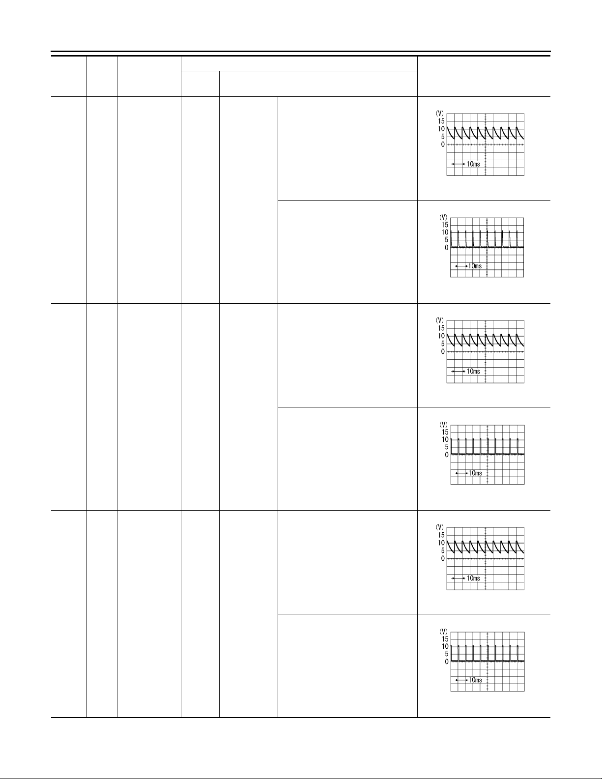
TKWM4375E
INFOID:0000000001328548
WW-10
Page 11
FRONT WIPER AND WASHER SYSTEM
Revision: 2007 April
2008 FX35/FX45
< SERVICE INFORMATION >
Termi-
nal No.
Wire
color
4PU/W
5Y/R
Signal name
Combination
switch input 3
Combination
switch input 2
Ignition
switch
ON
ON
Measuring condition
Lighting, turn,
wiper switch
(Wiper intermittent dial
position 4)
Lighting, turn,
wiper switch
Operation or condition
OFF Approx. 0 V
Any of the conditions below
• Front wiper switch MIST
• Front wiper switch INT
• Front wiper switch LO
OFF
(Wiper intermittent dial position 4)
Any of the conditions below
• Front washer switch
(Wiper intermittent dial position 4)
• Wiper intermittent dial position 1
• Wiper intermittent dial position 5
• Wiper intermittent dial position 6
OFF
(Wiper intermittent dial position 4)
Reference value
Approx. 1.0 V
Approx. 0 V
Approx. 1.0 V
Approx. 0 V
PKIB4959J
PKIB4959J
A
B
C
D
E
F
G
H
I
6SB
Combination
switch input 1
ON
Lighting, turn,
wiper switch
Any of the conditions below
• Front wiper switch HI
(Wiper intermittent dial position 4)
• Wiper intermittent dial position 3
Any of the conditions below
• Wiper intermittent dial position 1
• Wiper intermittent dial position 2
Any of the conditions below
• Wiper intermittent dial position 6
• Wiper intermittent dial position 7
Approx. 1.0 V
Approx. 1.7 V
Approx. 0.8 V
PKIB4959J
PKIB4952J
PKIB4955J
J
WW
L
M
N
O
P
WW-11
Page 12
FRONT WIPER AND WASHER SYSTEM
Revision: 2007 April
2008 FX35/FX45
< SERVICE INFORMATION >
Termi-
nal No.
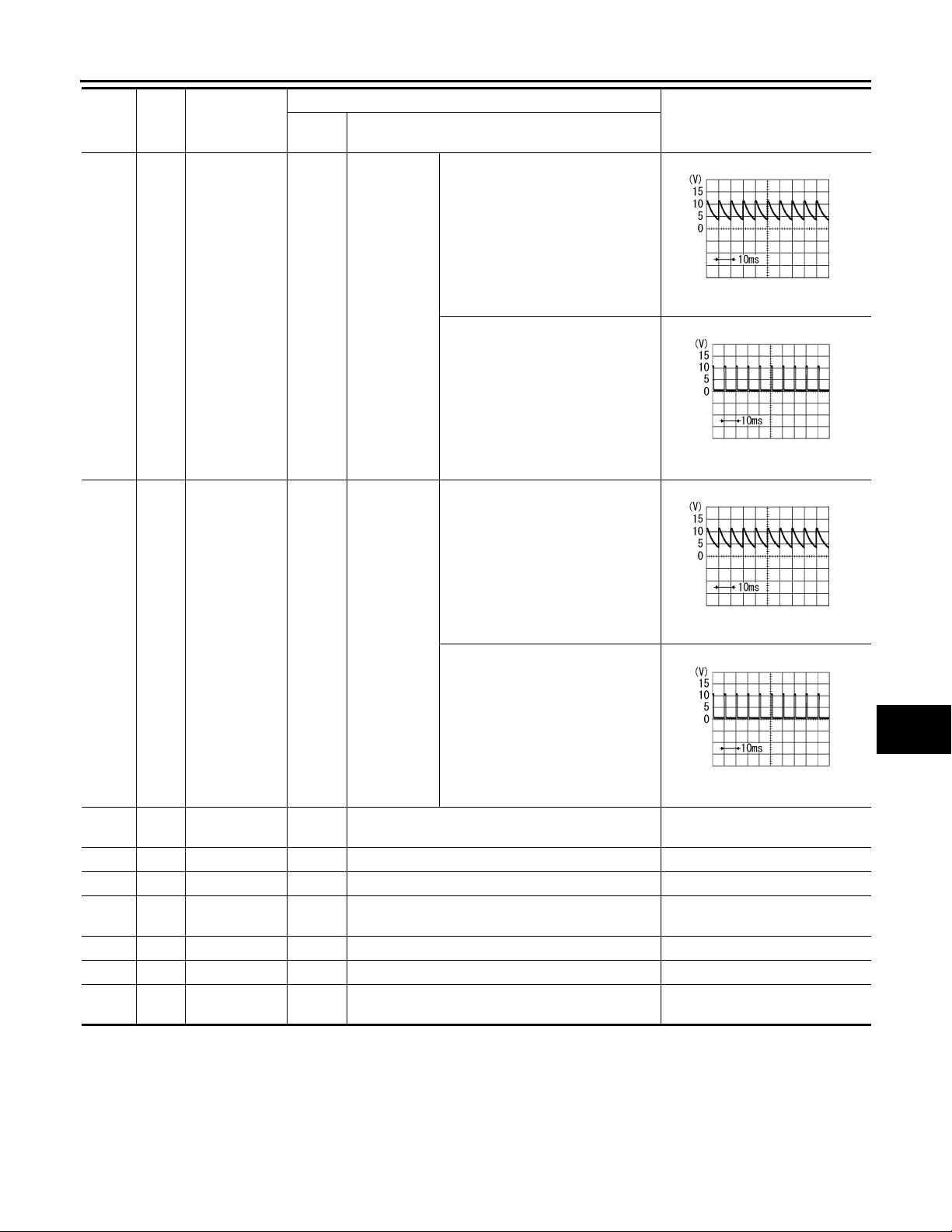
32 GY/R
Wire
color
Signal name
Combination
switch output 5
Ignition
switch
ON
Measuring condition
Lighting, turn,
wiper switch
Operation or condition
OFF
(Wiper intermittent dial position 4)
Any of the conditions below
• Wiper intermittent dial position 1
• Wiper intermittent dial position 2
• Wiper intermittent dial position 6
• Wiper intermittent dial position 7
Reference value
PKIB4960J
Approx. 7.2 V
PKIB4956J
Approx. 1.0 V
33 G
34 W/B
Combination
switch output 4
Combination
switch output 3
ON
ON
Lighting, turn,
wiper switch
Lighting, turn,
wiper switch
OFF
(Wiper intermittent dial position 4)
PKIB4960J
Approx. 7.2 V
Any of the conditions below
• Wiper intermittent dial position 1
• Wiper intermittent dial position 5
• Wiper intermittent dial position 6
PKIB4958J
Approx. 1.2 V
OFF
(Wiper intermittent dial position 4)
PKIB4960J
Approx. 7.2 V
Any of the conditions below
• Wiper intermittent dial position 1
• Wiper intermittent dial position 2
• Wiper intermittent dial position 3
PKIB4958J
Approx. 1.2 V
WW-12
Page 13
FRONT WIPER AND WASHER SYSTEM
Revision: 2007 April
2008 FX35/FX45
< SERVICE INFORMATION >
Termi-
nal No.
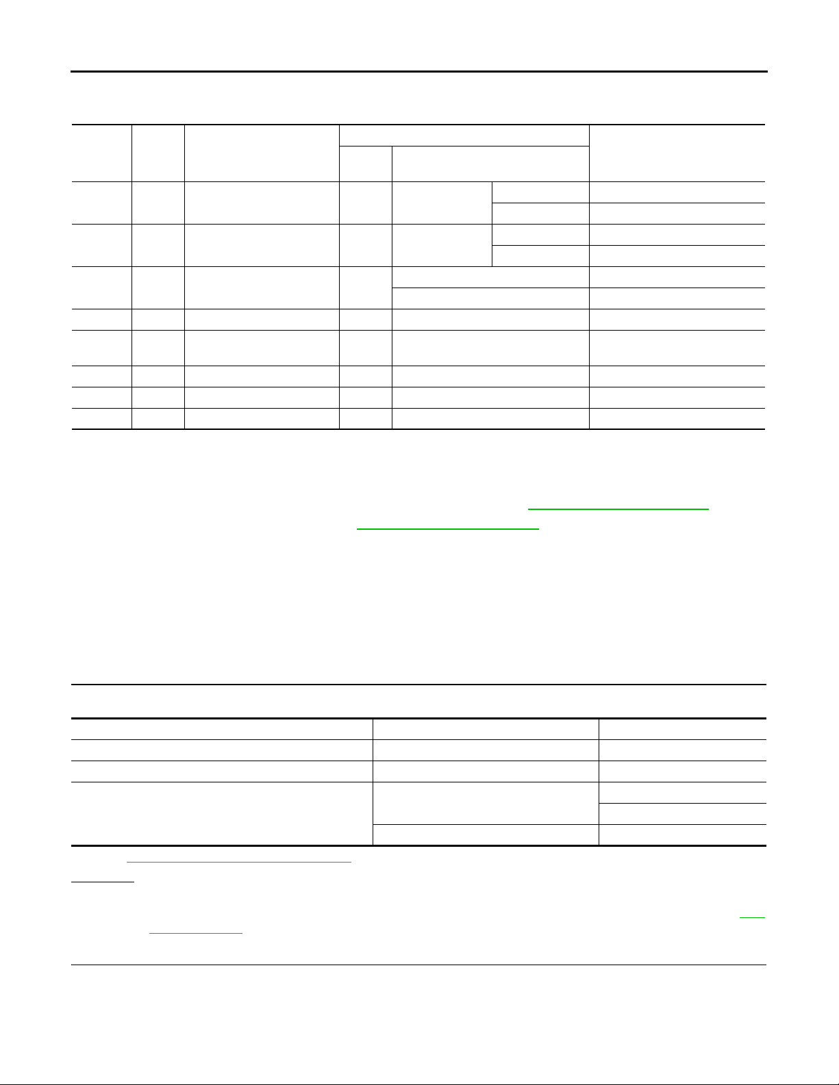
35 W/G
Wire
color
Signal name
Combination
switch output 2
Ignition
switch
ON
Measuring condition
Lighting, turn,
wiper switch
(Wiper intermittent dial
position 4)
Operation or condition
OFF
Any of the conditions below
• Front wiper switch INT
• Front wiper switch HI
OFF
Reference value
Approx. 7.2 V
Approx. 1.2 V
A
B
C
PKIB4960J
D
E
F
PKIB4958J
G
H
Lighting, turn,
36 W/R
38 W/L
39 L CAN-H — — —
40 P CAN-L — — —
42 L/R
49 B Ground ON — Approx. 0 V
52 B Ground ON — Approx. 0 V
55 G
Combination
switch output 1
Ignition switch
(ON)
Battery power
supply
Battery power
supply
OFF — Battery voltage
OFF — Battery voltage
wiper switch
ON
(Wiper intermittent dial
position 4)
Any of the conditions below
• Front wiper switch MIST
• Front wiper switch LO
• Front washer switch
ON — Battery voltage
Approx. 7.2 V
Approx. 1.2 V
PKIB4960J
PKIB4958J
I
J
WW
L
M
N
O
P
WW-13
Page 14
FRONT WIPER AND WASHER SYSTEM
Revision: 2007 April
2008 FX35/FX45
< SERVICE INFORMATION >
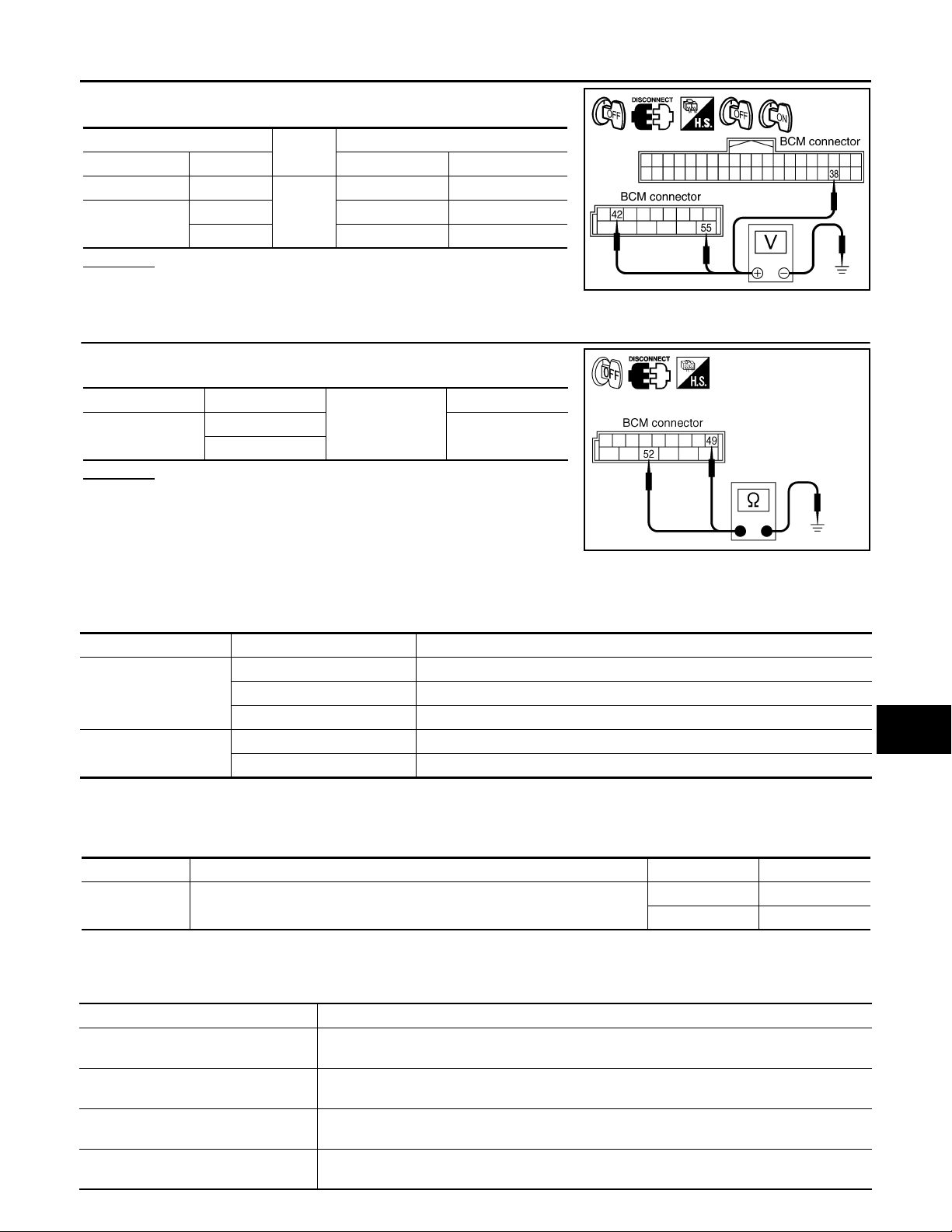
Terminal and Reference Value for IPDM E/R
Terminal
No.
21 P Low speed signal ON Wiper switch
31 PU High speed signal ON Wiper switch
32 L Wiper auto - stop signal ON
38 B Ground ON — Approx. 0 V
44 OR
48 L CAN-H — — —
49 R CAN-L — — —
60 B Ground ON — Approx. 0 V
Wire
color
Signal name
Front and rear washer pump
power supply
Ignition
switch
ON — Battery voltage
Measuring condition
Operation or condition
OFF Approx. 0 V
LOW Battery voltage
OFF Approx. 0 V
HI Battery voltage
Wiper operating Battery voltage
Wiper stopped Approx. 0 V
Reference value
INFOID:0000000001328549
How to Proceed with Trouble Diagnosis INFOID:0000000001328550
1. Confirm the symptoms and customer complaint.
2. Understand operation description and function description. Refer to WW-4, "
3. Perform the Preliminary Check. Refer to WW-14, "
Preliminary Check".
System Description".
4. Check symptom and repair or replace the cause of malfunction.
5. Does the front wiper and washer operate normally? If YES, GO TO 6. If NO, GO TO 4.
6. INSPECTION END
Preliminary Check INFOID:0000000001328551
CHECK POWER SUPPLY AND GROUND CIRCUIT
1.CHECK FUSE
Check for blown fuses.
Unit Power source Fuse and fusible link No.
Front and Rear washer pump Ignition switch ON or START 84
Front wiper motor, front wiper relay, front wiper HI relay Battery 73
M
22
Refer to WW-8, "
BCM
Wiring Diagram - WIPER -".
Battery
Ignition switch ON or START 1
OK or NG
OK >> GO TO 2
NG >> If fuse is blown, be sure to eliminate cause of malfunction before installing new fuse, Refer to PG-
3, "Schematic".
2.CHECK POWER SUPPLY CIRCUIT
1. Turn ignition switch OFF.
2. Disconnect BCM connector.
WW-14
Page 15
FRONT WIPER AND WASHER SYSTEM
Revision: 2007 April
2008 FX35/FX45
< SERVICE INFORMATION >
3. Check voltage between BCM harness connector and ground.
(+)
BCM connector Terminal OFF ON
M3 38
M4
42 Battery voltage Battery voltage
55 Battery voltage Battery voltage
(-)
Ground
Ignition switch position
Approx. 0 V Battery voltage
OK or NG
OK >> GO TO 3.
NG >> Repair harness or connector.
3.CHECK GROUND CIRCUIT
A
B
C
PKIA7520E
D
Check continuity between BCM harness connector and ground.
BCM connector Terminal
M4
49
52
Ground
Continuity
Yes
OK or NG
OK >> INSPECTION END
NG >> Repair harness or connector.
SKIA5294E
CONSULT-III Functions (BCM) INFOID:0000000001328552
CONSULT-III can display each diagnostic item using the diagnostic test mode shown following.
BCM diagnosis position Diagnosis mode Description
WORK SUPPORT Changes the setting for each function.
WIPER
BCM
WORK SUPPORT
DATA MONITOR Displays BCM input data in real time.
ACTIVE TEST Device operation can be checked by applying a drive signal to device.
SELF-DIAG RESULTS BCM performs self-diagnosis of CAN communication.
CAN DIAG SUPPORT MNTR The result of transmit/receive diagnosis of CAN communication can be read.
E
F
G
H
I
J
WW
L
Display Item List
Item Description CONSULT-III Factory setting
WIPER SPEED
SETTING
DATA MONITOR
Display Item List
IGN ON SW “ON/OFF”
IGN SW CAN “ON/OFF”
FR WIPER HI “ON/OFF”
FR WIPER LOW “ON/OFF”
Vehicle speed sousing type wiper control mode can be changed in this mode.
Vehicle speed sousing type wiper control mode between two ON/OFF.
Monitor item Contents
Displays status (ignition switch IGN position: ON/other: OFF) of ignition switch judged from the
ignition switch signal.
Displays status (ignition switch IGN position: ON/other: OFF) of ignition switch judged from the
ignition switch signal (CAN communication lines).
Displays status (front wiper switch high position: ON/other: OFF) of front wiper high switch
judged from the front wiper switch signal.
Displays status (front wiper switch low position: ON/other: OFF) of front wiper low switch
judged from the front wiper switch signal.
WW-15
ON ×
OFF —
M
N
O
P
Page 16
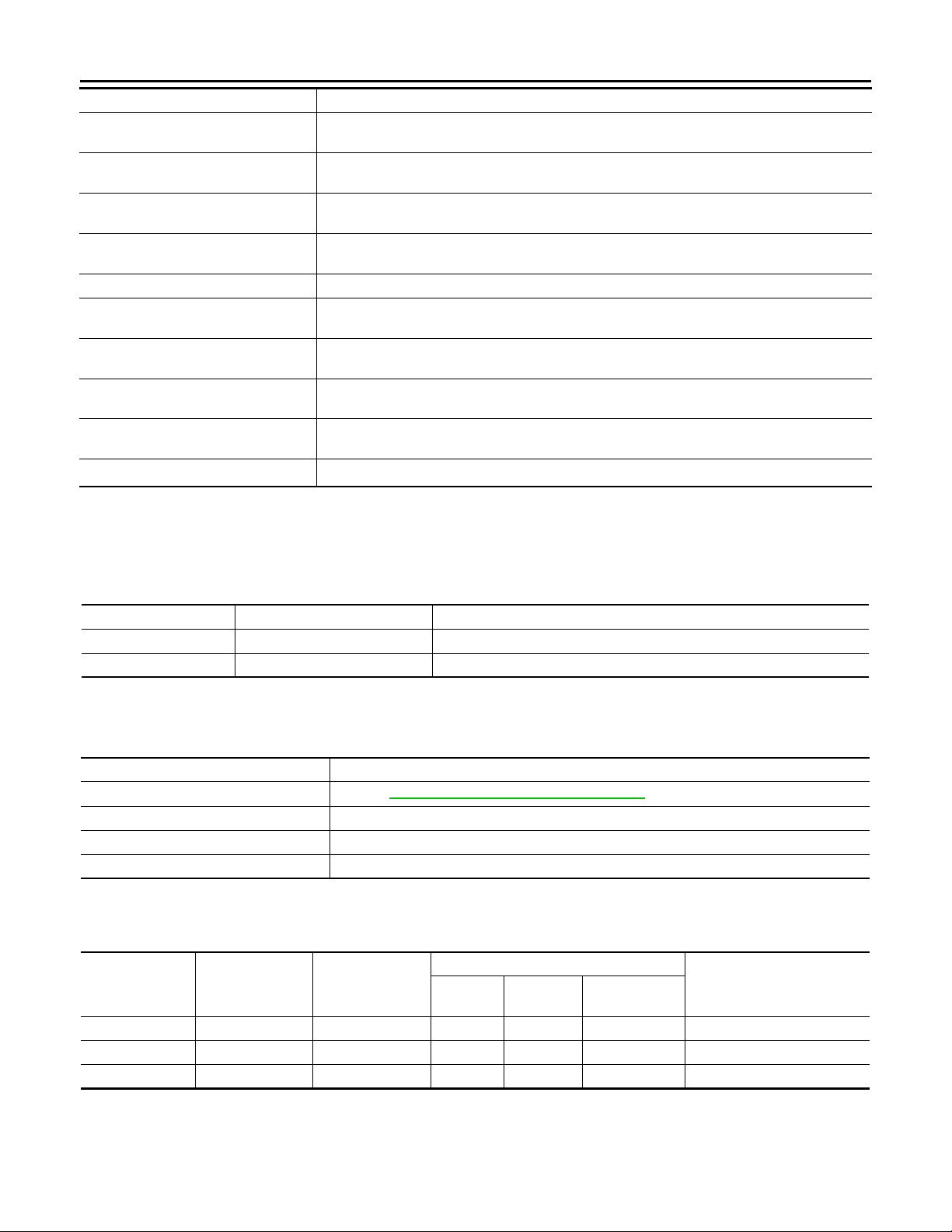
FRONT WIPER AND WASHER SYSTEM
Revision: 2007 April
2008 FX35/FX45
< SERVICE INFORMATION >
Monitor item Contents
FR WIPER INT “ON/OFF”
FR WASHER SW “ON/OFF”
INT VOLUME “1 - 7”
FR WIPER STOP “ON/OFF”
VEHICLE SPEED “km/h” Displays status vehicle speed as judged from vehicle speed signal.
RR WIPER ON “OFF”
RR WIPER INT “OFF”
RR WASHER SW “OFF”
RR WIPER STOP “OFF”
H/L WASH SW
NOTE:
This item is displayed, but cannot be monitored.
NOTE
“ON/OFF” —
Displays status (front wiper switch intermittent position: ON/other: OFF) of front wiper intermittent switch judged from the front wiper switch signal.
Displays status (front washer switch ON position: ON/other: OFF) of front washer switch
judged from the front wiper switch signal.
Displays status (wiper intermittent dial position setting 1- 7) of intermittent volume switch
judged from the front wiper switch signal.
Displays status (front wiper stop position: ON/move: OFF) of front wiper motor stop judged
from the front wiper auto stop signal.
Displays status (rear wiper switch ON position: ON/other: OFF) of rear wiper switch judged
from the rear wiper switch signal.
Displays status (rear wiper switch intermittent position: ON/other: OFF) of rear wiper intermittent switch judged from the rear wiper swi tch signal.
Displays status (rear washer switch ON position: ON/other: OFF) of rear washer switch judged
from the rear wiper switch signal.
Displays status (rear wiper stop position: OFF/move: ON) of rear wiper motor stop judged from
the rear wiper auto stop signal.
ACTIVE TEST
Display Item List
T est item Display on CONSULT-III screen Description
Front wiper output FR WIPER With a certain operation (OFF, HI, LO, INT), front wiper can be operated.
Rear wiper output RR WIPER Rear wiper can be operated by any ON-OFF operation
CONSULT-III Functions (IPDM E/R) INFOID:0000000001328553
CONSULT-III can display each diagnostic item using the diagnostic test mode shown following.
Diagnosis Mode Description
SELF-DIAG RESULTS Refer to PG-18, "
DATA MONITOR The input/output data of IPDM E/R is displayed in real time.
CAN DIAG SUPPORT MNTR The result of transmit/receive diagnosi s of CAN communication can be read.
ACTIVE TEST IPDM E/R sends a drive signal to electron ic components to check their operation.
DATA MONITOR
All Signals, Main Signals, Selection From Menu
Item name
FR wiper request FR WIP REQ STOP/LOW/HI ×× ×Signal status input from BCM
Wiper auto stop WIP AUTO STOP ACT P/STOP P ×× ×Output status of IPDM E/R
Wiper protection W IP PROT OFF/BLOCK ×× ×Control status of IPDM E/R
NOTE:
Perform monitoring of IPDM E/R data with ignition switch ON. When ignition switch is at ACC, the display may
not be correct.
CONSULT-III
screen display
Display or unit
CONSULT-III Function (IPDM E/R)".
Monitor item selection
ALL
SIGNALS
MAIN
SIGNALS
SELECTION
FROM MENU
Description
ACTIVE TEST
WW-16
Page 17

FRONT WIPER AND WASHER SYSTEM
Revision: 2007 April
2008 FX35/FX45
< SERVICE INFORMATION >
Test item CONSULT-III screen display Description
Front wiper (HI, LO) output FR WIPER
With a certain operation (OFF, HI ON, LO ON), front wiper relay (Lo, Hi)
can be operated.
Front Wiper Does Not Operate INFOID:0000000001328554
CAUTION:
During IPDM E/R fail-safe control, front wipers may not operate. Refer to PG-17, "
System Description"
in “PG IPDM E/R” to make sure that it is not in fail-safe status.
1.ACTIVE TEST
With CONSULT-III
1. Select “FRONT WIPER” of IPDM E/R active test item.
2. With operating the test item, check that front wiper “LO” and “HI” operation.
Without CONSULT-III
Start up auto active test. Refer to PG-20, "
Auto Active Test".
Does front wiper operate normally?
YES >> GO TO 5.
NO >> GO TO 2.
2.CHECK FRONT WIPER CIRCUIT
1. Turn ignition switch OFF.
2. Disconnect IPDM E/R connector and front wiper motor connector.
3. Check continuity between IPDM E/R harness connector and
front wiper motor harness connector.
A
B
C
D
E
F
G
H
IPDM E/R Front wiper motor
Connector Terminal Connector Terminal
E7
21
31 4
E57
1
Continuity
Yes
4. Check continuity between IPDM E/R harness connector and
Ground.
IPDM E/R connector Terminal
E7
21
31
Ground
Continuity
No
OK or NG
OK >> GO TO 3.
NG >> Repair harness or connector.
3.CHECK GROUND CIRCUIT
Check continuity between front wiper motor harness connector and
ground.
2 – Ground : Continuity should exist.
OK or NG
OK >> GO TO 4.
NG >> Repair harness or connector.
PKIA7650E
I
J
WW
L
M
N
O
P
4.CHECK IPDM E/R
PKIA5193E
WW-17
Page 18
FRONT WIPER AND WASHER SYSTEM
Revision: 2007 April
2008 FX35/FX45
< SERVICE INFORMATION >
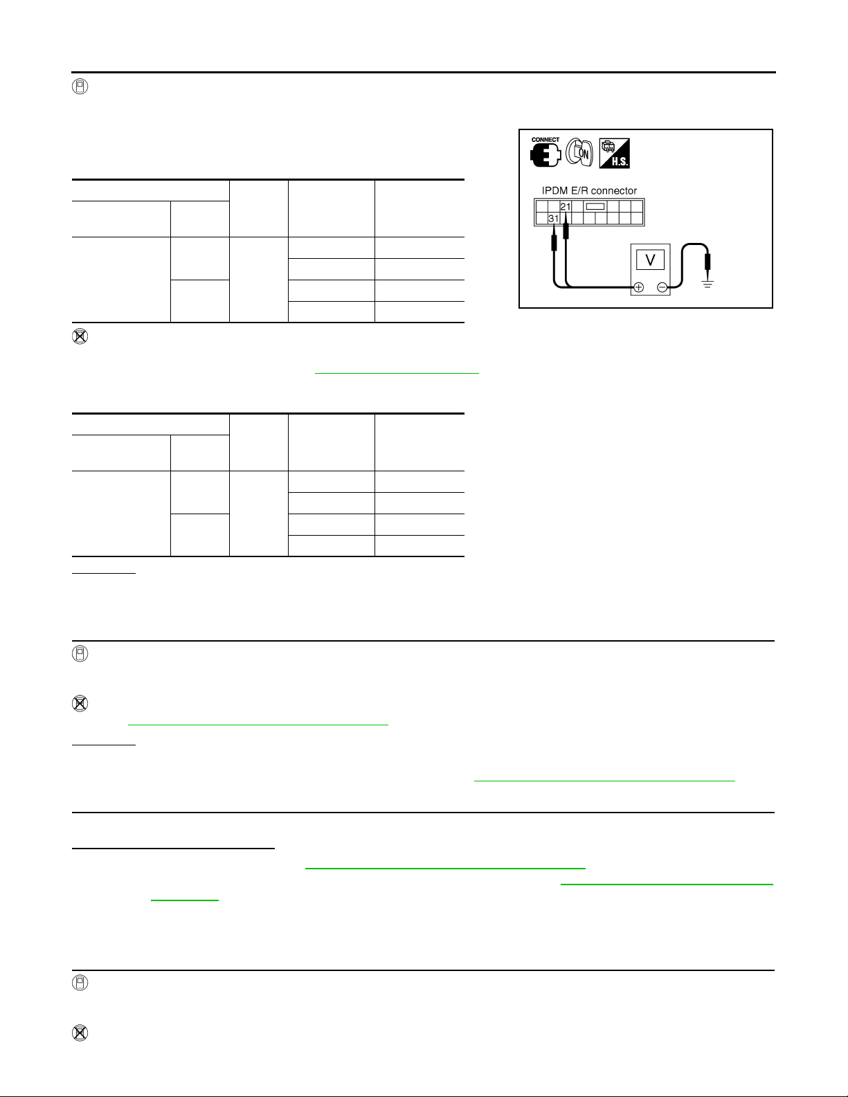
With CONSULT-III
1. Connect IPDM E/R connector and front wiper motor connector.
2. Select “FRONT WIPER” of IPDM E/R active test item.
3. With operating the test item, check voltage between IPDM E/R
harness connector and ground.
IPDM E/R
connector
E7
(+)
Terminal
21
31
(-) Condition
Stopped 0 V
Ground
LO operation Battery voltage
Stopped 0 V
HI operation Battery voltage
Voltage
(Approx.)
Without CONSULT-III
1. Connect IPDM E/R connector and front wiper motor connector.
2. Start up auto active test. Refer to PG-20, "
Auto Active Test".
3. Check voltage between IPDM E/R harness connector and ground.
IPDM E/R
connector
E7
(+)
Terminal
21
31
(-) Condition
Stopped 0 V
Ground
LO operation Battery voltage
Stopped 0 V
HI operation Battery voltage
Voltage
(Approx.)
OK or NG
OK >> Replace front wiper motor.
NG >> Replace IPDM E/R.
5.CHECK CIRCUIT BETWEEN COMBINATION SWITCH AND BCM
PKIA5194E
With CONSULT-III
1. Select “FR WIPER INT”, “FR WIPER LOW”, and “FR WIPER HI” of BCM data monitor item.
2. With operating the wiper switch, check the monitor status.
Without CONSULT-III
Refer to LT-104, "
Combination Switch Inspection".
OK or NG
OK >> GO TO 6.
NG >> Check combination switch (wiper switch). Refer to LT-104, "
Combination Switch Inspection".
6.CHECK CIRCUIT BETWEEN IPDM E/R AND BCM
Select “BCM” on CONSULT-III, and perform self-diagnosis for “BCM”.
Displayed self
-diagnosis results
NO DTC>>Replace BCM. Refer to BCS-13, "Removal and Installation of BCM".
CAN COMM CIRCUIT>>Check CAN communication line of BCM. Refer to LAN-43, "
CAN System Specifica-
tion Chart".
Front Wiper Does Not Return to Stop Position INFOID:0000000001328555
1.CHECK FRONT WIPER STOP SIGNAL
With CONSULT-III
1. Select “WIP AUTO STOP” of IPDM E/R data monitor item.
2. Check that “WIP AUTO STOP” turns “ACT P” - “STOP P” linked with wiper operation.
Without CONSULT-III
GO TO 2.
WW-18
Page 19
FRONT WIPER AND WASHER SYSTEM
Revision: 2007 April
2008 FX35/FX45
< SERVICE INFORMATION >
OK or NG
OK >> Replace IPDM E/R.
NG >> GO TO 2.
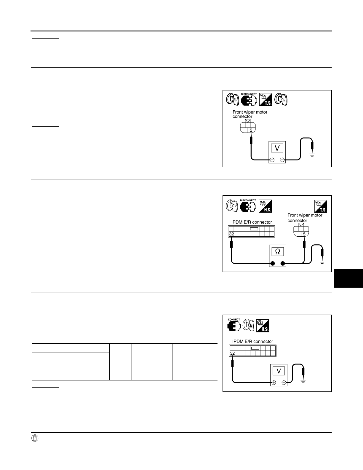
2.CHECK IPDM E/R
1. Turn ignition switch OFF.
2. Disconnect front wiper motor connector.
3. Turn ignition switch ON.
4. Check voltage between front wiper harness connector and
ground.
A
B
C
5 – Ground : Battery voltage.
OK or NG
OK >> GO TO 4.
NG >> GO TO 3.
3.CHECK FRONT WIPER AUTO STOP CIRCUIT
1. Turn ignition switch OFF.
2. Disconnect IPDM E/R connector.
3. Check continuity between IPDM E/R harness connector and
front wiper motor harness connector.
32 – 5 : Continuity should exist.
4. Check continuity between IPDM E/R harness connector and
ground.
32 – Ground : Continuity should not exist.
OK or NG
OK >> Replace IPDM E/R.
NG >> Repair harness or connector.
4.CHECK IPDM E/R
PKIA7662E
PKIA5195E
D
E
F
G
H
I
J
WW
1. Turn ignition switch OFF.
2. Connect front wiper motor connector.
3. Turn ignition switch ON.
4. Check voltage between IPDM E/R harness connector and
ground while front wiper motor is stopped and while it is operating.
IPDM E/R connector Terminal
OK or NG
OK >> Replace IPDM E/R.
NG >> Replace front wiper motor.
Only Front Wiper Low Does Not Operate INFOID:0000000001328556
1.ACTIVE TEST
With CONSULT-III
1. Select “FRONT WIPER” of IPDM E/R active test item.
(+)
E7 32 Ground
(-) Condition
Voltage
(Approx.)
Wiper stopped 0 V
Wiper operating Battery voltage
WW-19
L
M
N
O
PKIA5196E
P
Page 20
FRONT WIPER AND WASHER SYSTEM
Revision: 2007 April
2008 FX35/FX45
< SERVICE INFORMATION >
2. With operating the test item, check that front wiper “LO” operation.
Without CONSULT-III
Start up auto active test. Refer to PG-20, "
Does front wiper operate normally?
YES >> Check combination switch (wiper switch). Refer to LT-104, "Combination Switch Inspection".
NO >> GO TO 2.
Auto Active Test"
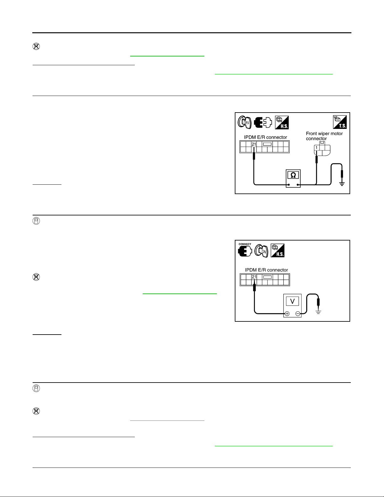
2.CHECK FRONT WIPER MOTOR CIRCUIT
1. Turn ignition switch OFF.
2. Disconnect IPDM E/R connector and front wiper motor connector.
3. Check continuity between IPDM E/R harness connector and
front wiper motor harness connector.
21 – 1 : Continuity should exist.
4. Check continuity between IPDM E/R harness connector and
ground.
21 – Ground : Continuity should not exist.
OK or NG
OK >> GO TO 3.
NG >> Repair harness or connector.
3.CHECK IPDM E/R
PKIB6024E
With CONSULT-III
1. Connect IPDM E/R connector and front wiper motor connector.
2. Select “FRONT WIPER” of IPDM E/R active test item.
3. With operating the test item, check voltage between IPDM E/R
harness connector and ground.
21 – Ground : Battery voltage.
Without CONSULT-III
1. Connect IPDM E/R connector and front wiper motor connector.
2. Start up auto active test. Refer to PG-20, "
3. Check voltage between IPDM E/R harness connector and
ground.
21 – Ground : Battery voltage.
OK or NG
OK >> Replace front wiper motor.
NG >> Replace IPDM E/R.
Auto Active Test".
SKIA9167E
Only Front Wiper High Does Not Operate INFOID:0000000001328557
1.ACTIVE TEST
With CONSULT-III
1. Select “FRONT WIPER” of IPDM E/R active test item.
2. With operating the test item, check that front wiper “HI” operation.
Without CONSULT-III
Start up auto active test. Refer to PG-20, "
Auto Active Test".
Does front wiper operate normally?
YES >> Check combination switch (wiper switch). Refer to LT-104, "Combination Switch Inspection".
NO >> GO TO 2.
2.CHECK FRONT WIPER MOTOR CIRCUIT
1. Turn ignition switch OFF.
WW-20
Page 21
FRONT WIPER AND WASHER SYSTEM
Revision: 2007 April
2008 FX35/FX45
< SERVICE INFORMATION >
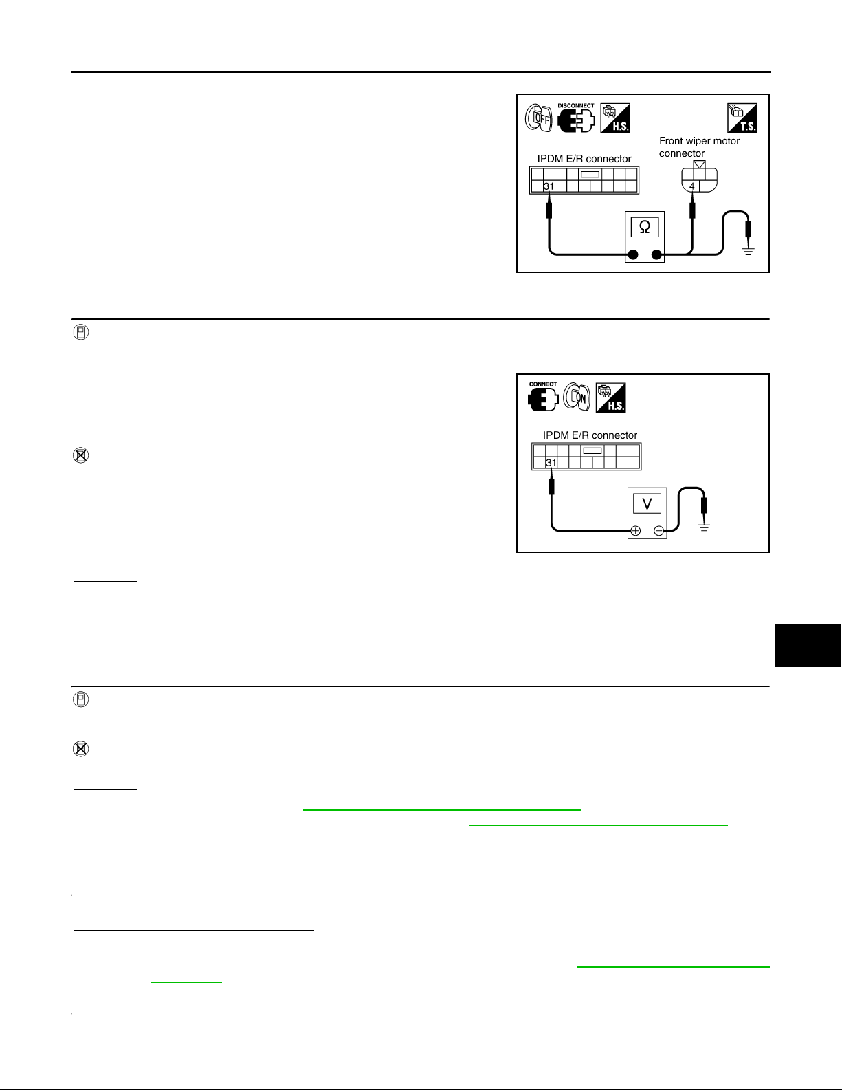
2. Disconnect IPDM E/R connector and front wiper motor connector.
3. Check continuity between IPDM E/R harness connector and
front wiper motor harness connector.
A
31 – 4 : Continuity should exist.
4. Check continuity between IPDM E/R harness connector and
ground.
31 – Ground : Continuity should not exist.
OK or NG
OK >> GO TO 3.
NG >> Repair harness or connector.
3.CHECK IPDM E/R
With CONSULT-III
1. Connect IPDM E/R connector and front wiper motor connector.
2. Select “FRONT WIPER” of IPDM E/R active test item.
3. With operating the test item, check voltage between IPDM E/R
harness connector and ground.
31 – Ground : Battery voltage.
Without CONSULT-III
1. Connect IPDM E/R connector and front wiper motor connector.
2. Start up auto active test. Refer to PG-20, "
3. Check voltage between IPDM E/R harness connector and
ground.
31 – Ground : Battery voltage.
Auto Active Test".
PKIA5197E
PKIA5198E
B
C
D
E
F
G
H
I
OK or NG
OK >> Replace front wiper motor.
NG >> Replace IPDM E/R.
Only Front Wiper Intermittent Does Not Operate INFOID:0000000001328558
1.CHECK COMBINATION SWITCH
With CONSULT-III
1. Select “FR WIPER INT” of BCM data monitor item.
2. With operating the front wiper switch, check the monitor status.
Without CONSULT-III
Refer to LT-104, "
OK or NG
OK >> Replace BCM. Refer to BCS-13, "Removal and Installation of BCM".
NG >> Check combination switch (wiper switch) Refer to LT-104, "
Combination Switch Inspection".
Combination Switch Inspection".
Front Wiper Interval Time Is Not Controlled by Vehicle Speed INFOID:0000000001328559
1.CHECK FUNCTION OF COMBINATION METER
Confirm that speedometer operates normally.
Does speedometer operate normally?
YES >> GO TO 2.
NO >> Combination meter vehicle speed system malfunction. Refer to DI-17, "
Inspection".
Vehicle Speed Signal
2.CHECK CAN COMMUNICATION BETWEEN BCM AND COMBINATION METER
J
WW
L
M
N
O
P
Select “BCM” on CONSULT-III, and perform self-diagnosis for “BCM”.
WW-21
Page 22

FRONT WIPER AND WASHER SYSTEM
Revision: 2007 April
2008 FX35/FX45
< SERVICE INFORMATION >
Displayed self-diagnosis results
NO DTC>>Replace BCM. Refer to BCS-13, "Removal and Installation of BCM".
CAN COMM CIRCUIT>>Check CAN communication line of BCM. Refer to LAN-43, "
tion Chart".
CAN System Specifica-
Front Wiper Intermittent Operation Switch Position Cannot Be Adjusted INFOID:0000000001328560
1.CHECK CIRCUIT BETWEEN COMBINATION SWITCH AND BCM
With CONSULT-III
1. Select “INT VOLUME” of BCM data monitor item.
2. Check that “INT VOLUME”, changes in order form 1 to 7 according to wiper switch operation.
Without CONSULT-III
Refer to LT-104, "
OK or NG
OK >> Replace BCM. Refer to BCS-13, "Removal and Installation of BCM".
NG >> Check combination switch (wiper switch). Refer to LT-104, "
Combination Switch Inspection".
Combination Switch Inspection".
Wiper Does Not Wipe When Front Washer Operates INFOID:0000000001328561
1.CHECK CIRCUIT BETWEEN COMBINATION SWITCH AND BCM
With CONSULT-III
1. Select “FR WASHER SW” of BCM data monitor item.
2. Check that “FR WASHER SW” turn ON-OFF according to front wiper switch operation.
Without CONSULT-III
Refer to LT-104, "
OK or NG
OK >> Replace BCM Refer to BCS-13, "Removal and Installation of BCM".
NG >> Check combination switch (wiper switch). Refer to LT-104, "
Combination Switch Inspection".
Combination Switch Inspection".
After Front Wiper Operate for 10 Seconds, They Stop for 20 Seconds, and After Repeating the Operation Five Times, They Become Inoperative
CAUTION:
• When auto-stop signal has not varied for 10 seconds or longer while IPDM E/R is operating front wip-
ers, IPDM E/R considers that front wipers are locked, and stops wiper output. That causes this symptom.
• This status can be checked by “DATA MONITOR” of “IPDM E/R” on which “WIPER PROTECTION”
item shows “BLOCK”.
INFOID:0000000001328562
1.CHECK WIPER MOTOR SIGNAL
With CONSULT-III
1. Select “WIP AUTO STOP” of BCM data monitor item.
2. Check that “WIP AUTO STOP” turns “ACT P” - “STOP P” linked with wiper operation.
Without CONSULT-III
GO TO 2.
OK or NG
OK >> Replace IPDM E/R.
NG >> GO TO 2.
2.CHECK WIPER AUTO STOP CIRCUIT
1. Turn ignition switch OFF.
2. Disconnect IPDM E/R connector and front wiper motor connector.
WW-22
Page 23
FRONT WIPER AND WASHER SYSTEM
Revision: 2007 April
2008 FX35/FX45
< SERVICE INFORMATION >
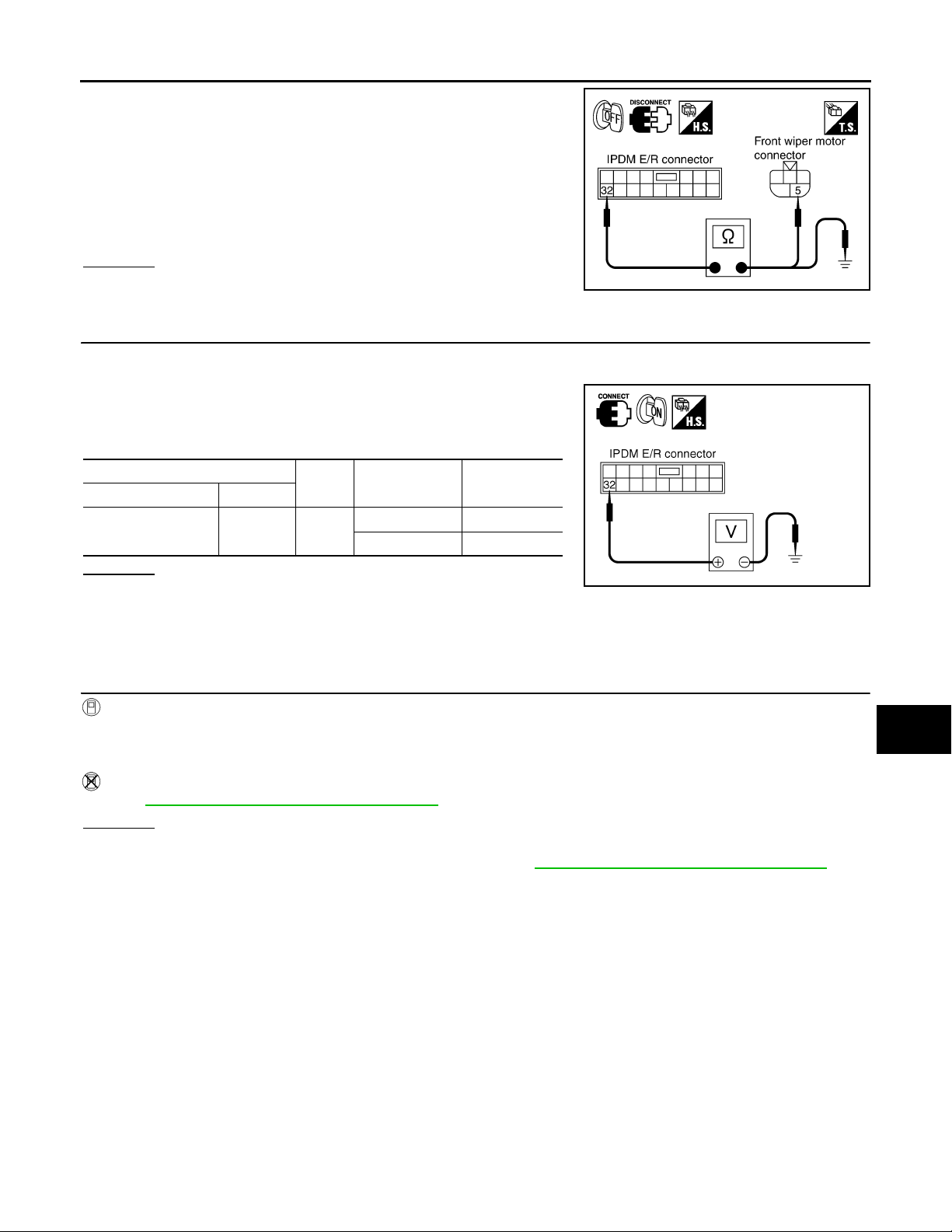
3. Check continuity between IPDM E/R harness connector and
front wiper motor harness connector.
32 – 5 : Continuity should exist.
4. Check continuity between IPDM E/R harness connector and
ground.
A
B
32 – Ground : Continuity should not exist.
OK or NG
OK >> GO TO 3.
PKIA5195E
NG >> Repair harness or connector.
3.CHECK FRONT WIPER MOTOR
1. Connect IPDM E/R connector and front wiper connector.
2. Turn ignition switch ON.
3. Check voltage between IPDM E/R harness connector and
ground while front wiper motor is stopped and while it is operating.
(+)
IPDM E/R connector Terminal
E7 32 Ground
OK or NG
(-) Condition
Wiper stopped 0 V
Wiper operating Battery voltage
Voltage
(Approx.)
PKIA5196E
OK >> Replace IPDM E/R.
NG >> Replace front wiper motor.
Front Wiper Does Not Stop INFOID:0000000001328563
1.CHECK CIRCUIT BETWEEN COMBINATION SWITCH AND BCM
C
D
E
F
G
H
I
J
With CONSULT-III
1. Select “FR WIPER INT”, “FR WIPER LOW”, “FR WIPER HI”, and “FR WASHER SW” of BCM data monitor item.
2. With operating the wiper switch, check the monitor status.
Without CONSULT-III
Refer to LT-104, "
Combination Switch Inspection".
OK or NG
OK >> Replace IPDM E/R.
NG >> Check combination switch (wiper switch). Refer to LT-104, "
Combination Switch Inspection".
Removal and Installation of Front Wiper Arms, Adjustment of Wiper Arms Stop Location
REMOVA L
1. Turn front wiper switch ON to operate wiper motor, and then turn front wiper switch OFF (auto stop).
2. Open hood, remove front wiper arm caps, and remove washer tube from washer tube joint.
3. Remove front wiper arm nuts.
4. Raise front wiper arms, and remove front wiper arms from the vehicle.
INSTALLATION
INFOID:0000000001328564
WW
L
M
N
O
P
WW-23
Page 24
FRONT WIPER AND WASHER SYSTEM
Revision: 2007 April
2008 FX35/FX45
< SERVICE INFORMATION >
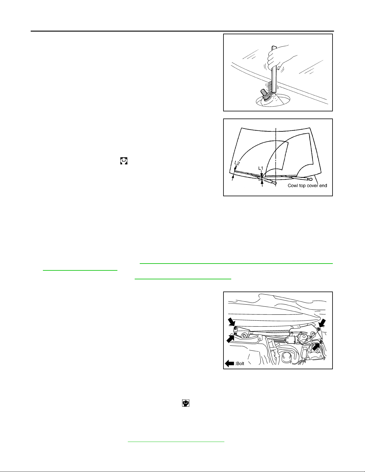
1. Clean up the pivot area as shown in the figure. This will reduce
possibility of front wiper arm nuts looseness.
2. Prior to front wiper arms installation, turn front wiper switch ON
to operate wiper motor, and then turn front wiper switch OFF
(auto stop).
3. Install washer tube to washer tube joint.
4. Lift the blade up and then set it down onto windshield glass surface to set the blade center to clearance “L1” & “L2” immediately.
5. Tighten front wiper arm nuts to specified torque.
Front wiper arm nuts : 23.6 N·m (2.4 kg-m, 17 ft-lb)
6. Spray washer fluid. Turn on wiper switch ON to operate wiper
motor, and then turn front wiper switch OFF (auto stop).
7. Make sure that wiper blades stop within clearance “L1” & “L2”.
SEL024J
PKIA9951E
Clearance “L1” : 49.4 ± 5.0 mm (1.945 ± 0.2 in)
Clearance “L2” : 43.0 ± 5.0 mm (1.693 ± 0.2 in)
8. Install front wiper arm caps.
Removal and Installation of Front Wiper Drive Assembly INFOID:0000000001328565
REMOVA L
1. Remove front wiper arms. Refer to WW-23, "Removal and Installation of Front Wiper Arms, Adjustment of
Wiper Arms Stop Location".
2. Remove cowl top cover. Refer to EI-23, "
3. Remove washer tube.
4. Disconnect wiper motor connector.
5. Remove front wiper drive assembly mounting bolts, and remove
front wiper drive assembly from the vehicle.
INSTALLATION
1. Install front wiper drive assembly to the vehicle.
Component Parts Location".
SKIA5070E
2. Connect wiper motor connector. Turn front wiper switch ON to operate wiper motor, and then turn front
wiper switch OFF (auto stop).
3. Install washer tube to washer tube joint.
4. Install cowl top cover. Refer to EI-23, "
Front wiper drive assembly mounting bolt : 4.5 N·m (0.46 kg-m, 40 in-lb)
Component Parts Location".
WW-24
Page 25
FRONT WIPER AND WASHER SYSTEM
Revision: 2007 April
2008 FX35/FX45
< SERVICE INFORMATION >
5. Install front wiper arms and arm caps. Refer to WW-23, "Removal and Installation of Front Wiper Arms,
Adjustment of Wiper Arms Stop Location".
6. Install front wiper arm washer tube.
A
Disassembly and Assembly of Front Wiper Drive Assembly INFOID:0000000001328566
PKIC9716E
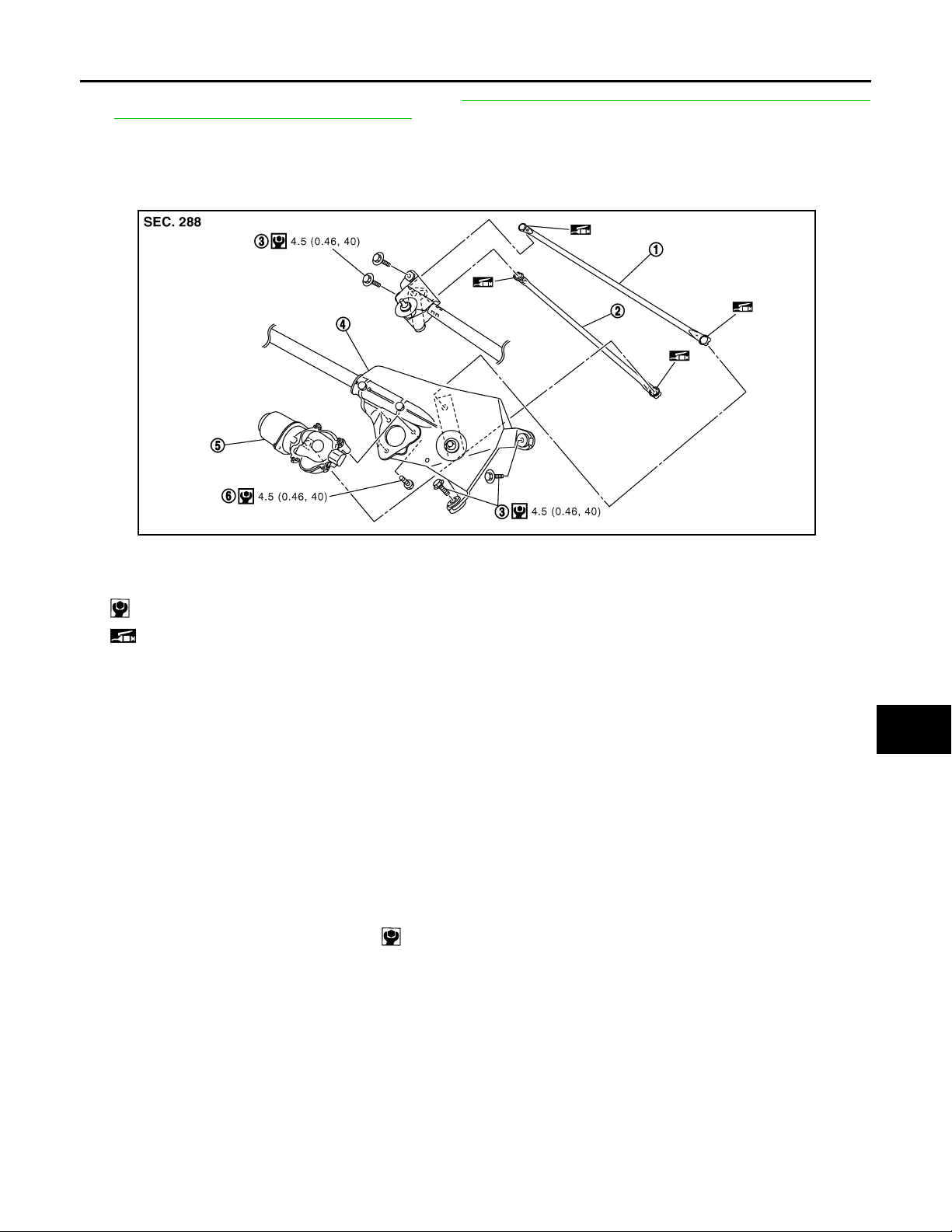
1. Wiper linkage 2 2. Wiper linkage 1 3. Wiper motor frame mounting bolt
4. Wiper motor mounting frame 5. Wiper motor 6. Wiper motor mounting bolt
: N·m (kg-m, in-lb)
: Should be lubricated with grease.
B
C
D
E
F
G
H
I
DISASSEMBLY
1. Remove wiper linkages from wiper motor and motor frame.
2. Remove wiper motor mounting bolts, and remove wiper motor from wiper motor mounting frame.
CAUTION:
Be careful not to bend wiper linkages and not to damage the resin part of ball joint when removing
wiper linkages.
ASSEMBLY
1. Connect wiper motor connector. Turn front wiper switch ON to operate wiper motor, and then turn front
wiper switch OFF (auto stop).
2. Disconnect wiper motor connector.
3. Install wiper motor to wiper motor mounting frame.
Wiper motor mounting bolts :4.5 N·m (0.46 kg-m, 40 in-lb)
4. Install wiper linkages to wiper frame and wiper motor.
CAUTION:
• Never drop the wiper motor or cause it to interfere with other parts.
• Check joint of motor arm and wiper linkages (at retainer) for grease conditions. Apply grease if nec-
essary.
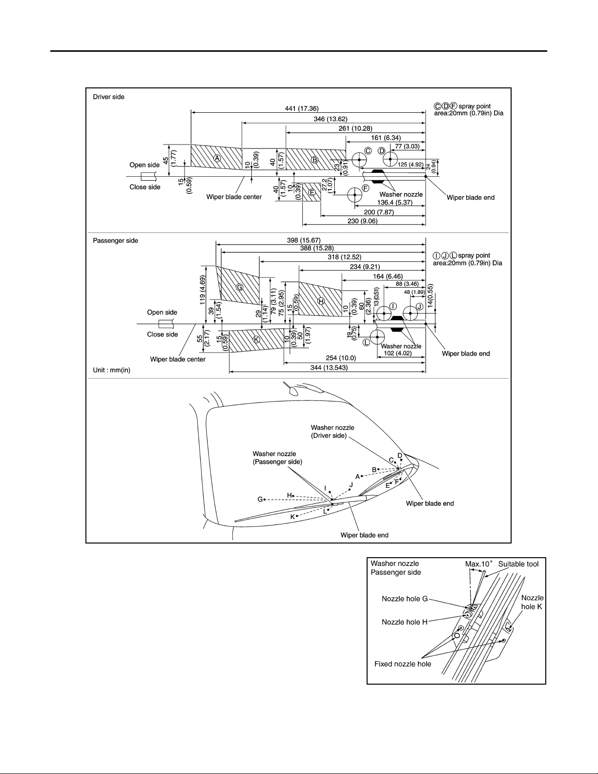
Washer Nozzle Adjustment INFOID:0000000001328567
1. When wiper blade position is in auto stop condition, remove wiper motor connector to ensure wiper arms
do not move.
2. Adjust each nozzle position (A, B, E, G, H, and K) so that spray positions are in the range of shaded parts.
CAUTION:
J
WW
L
M
N
O
P
WW-25
Page 26
FRONT WIPER AND WASHER SYSTEM
Revision: 2007 April
2008 FX35/FX45
< SERVICE INFORMATION >
Only washer nozzles (A, B, E, G, H, and K) can be adjusted. Washer nozzles (C, D, F, I, J, and L)
cannot be adjusted because of fixed nozzles.
PKIB3558E
SKIA5073E
WW-26
Page 27
FRONT WIPER AND WASHER SYSTEM
Revision: 2007 April
2008 FX35/FX45
< SERVICE INFORMATION >
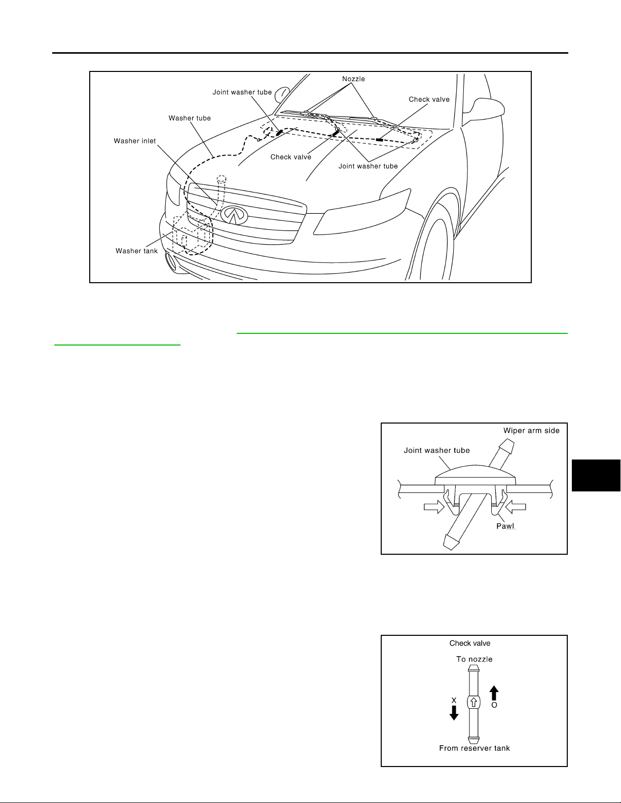
Washer Tube Layout INFOID:0000000001328568
A
B
C
D
E
PKID0570E
Removal and Installation of Front Washer Nozzle INFOID:0000000001328569
Replace wiper arm assembly. Refer to WW-23, "Removal and Installation of Front Wiper Arms, Adjustment of
Wiper Arms Stop Location".
CAUTION:
Removal/installation of the washer nozzle as a unit must not be done.
Removal and Installation of Front Washer Tube Joint INFOID:0000000001328570
REMOVA L
1. Remove upwards while pressing the pawls on reverse side.
2. Remove washer tube.
PKIA1159E
INSTALLATION
Installation is the reverse order of removal.
F
G
H
I
J
WW
L
M
Inspection of Washer Nozzle INFOID:0000000001328571
CHECK VALVE
Blow check valve. Confirm that the air ventilates. Also confirm that
inhalation is impossible.
CAUTION:
A check valve is provided in the washer fluid line. Be careful not
to connect check valve to washer tube in the wrong direction.
N
O
P
PKIA3131E
WW-27
Page 28
FRONT WIPER AND WASHER SYSTEM
Revision: 2007 April
2008 FX35/FX45
< SERVICE INFORMATION >
Inspection of Front Wiper and Washer Switch Circuit
INFOID:0000000001328572
Refer to LT-104, "Combination Switch Inspection".
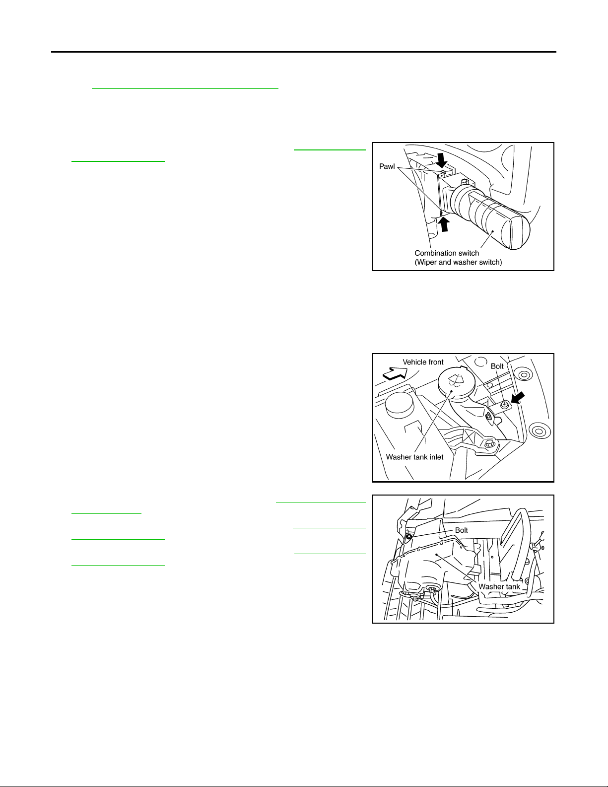
Removal and Installation of Front Wiper and Washer Switch INFOID:0000000001328573
REMOVA L
1. Remove steering column upper cover. Refer to IP-10, "Compo-
nent Parts Location".
2. Disconnect wiper and washer switch connector.
3. Pull wiper and washer switch toward the passenger door while
pressing pawls in direction shown by the arrow in the figure, and
remove it from the base.
PKIB6026E
INSTALLATION
Installation is the reverse order of removal.
Removal and Installation of Washer Tank INFOID:0000000001328574
REMOVA L
1. Remove bolt and pull out washer tank inlet out of washer tank.
2. Remove front fillet molding (RH). Refer to EI-14, "
Component
Parts Location".
3. Remove fender protector front (RH). Refer to EI-24, "
Compo-
nent Parts Location".
4. Remove front bumper fascia assembly. Refer to EI-14, "
Compo-
nent Parts Location".
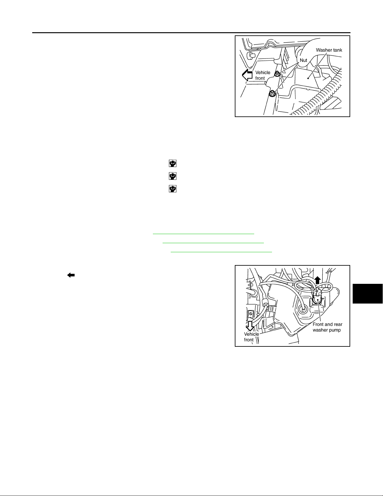
5. Disconnect washer pump connector and wash fluid level sensor
connector.
6. Remove washer tank mounting bolt and nuts.
SKIA5076E
PKIC9705E
WW-28
Page 29
FRONT WIPER AND WASHER SYSTEM
Revision: 2007 April
2008 FX35/FX45
< SERVICE INFORMATION >
7. Remove washer tube, and remove washer tank from the vehicle.
PKIC9707E
INSTALLATION
Installation is the reverse order of removal.
NOTE:
After installation, add water up to the upper level of the washer tank inlet, and check for water leaks.
Washer tank mounting bolt : 5.7 N·m (0.58 kg-m, 50 in-lb)
Washer tank mounting nut : 5.7 N·m (0.58 kg-m, 50 in-lb)
Washer tank inlet mounting bolt : 6.8 N·m (0.69 kg-m, 60 in-lb)
Removal and Installation of Front and Rear Washer Pump INFOID:0000000001328575
A
B
C
D
E
F
G
REMOVA L
1. Remove fillet molding (RH). Refer to EI-14, "Component Parts Location".
2. Remove fender protector (RH). Refer to EI-24, "
3. Remove bumper fascia assembly. Refer to EI-14, "
Component Parts Location".
Component Parts Location".
4. Disconnect washer pump connector and tube.
5. Pull out front and rear washer pump in direction shown by the
arrow ( ) in the figure. Remove front and rear washer pump
from washer tank.
INSTALLATION
Installation is the reverse order of removal.
NOTE:
When installing front and rear washer pump, there should be no packing twists, etc.
PKIC9706E
H
I
J
WW
L
M
N
O
P
WW-29
Page 30
REAR WIPER AND WASHER SYSTEM
Revision: 2007 April
2008 FX35/FX45
< SERVICE INFORMATION >
REAR WIPER AND WASHER SYSTEM
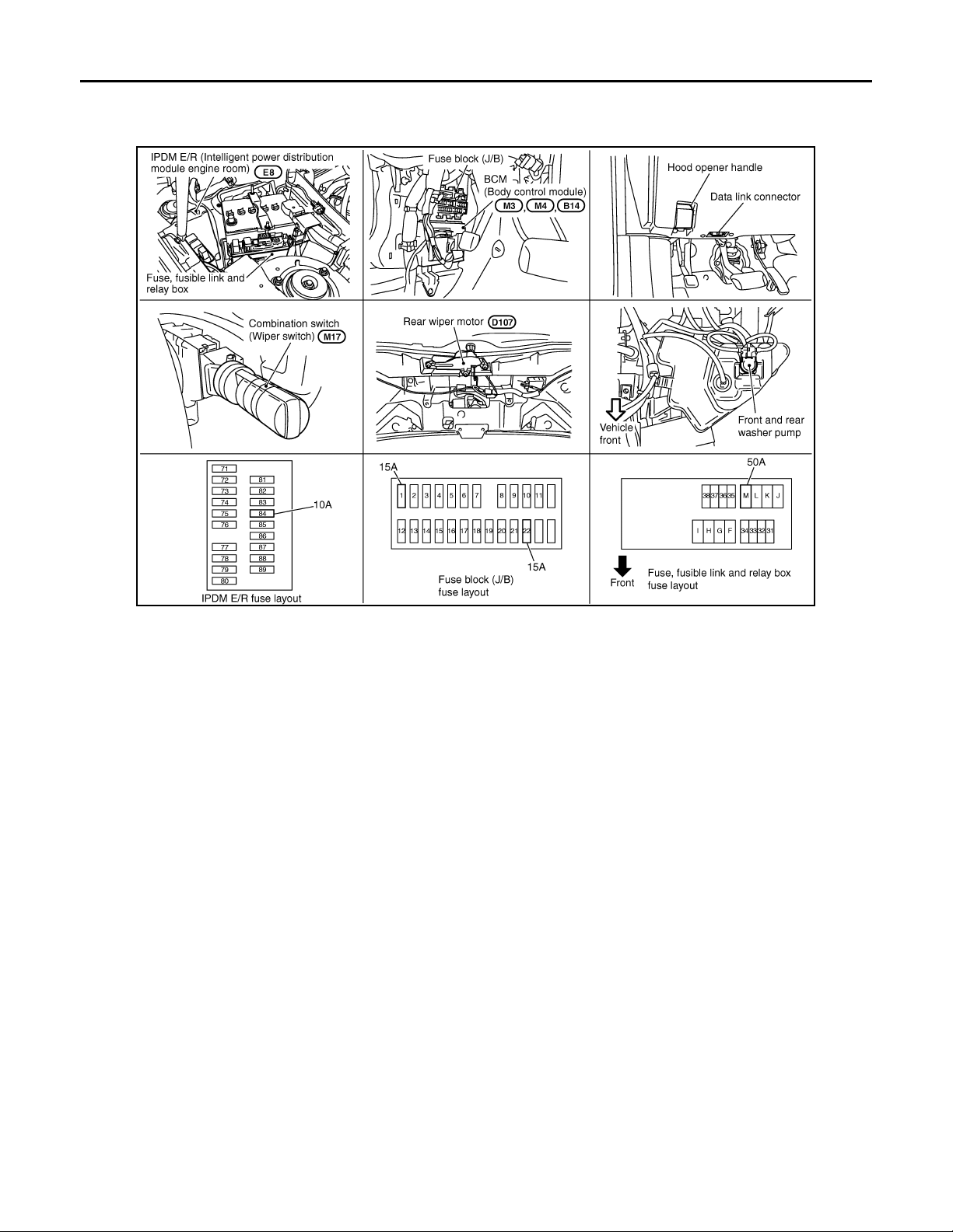
Component Parts and Harness Connector Location INFOID:0000000001328576
PKIC9708E
System Description INFOID:0000000001328577
• Wiper switch (combination switch) is composed of a combination of 5 output terminals and 5 input terminals.
Terminal combination status is read by BCM (body control module) when switch is turned ON.
• BCM controls rear wiper ON and INT (intermittent) operation.
Power supplied at all times
• through 50 A fusible link (letter M, located in fuse, fusible link and relay box)
• to BCM terminal 55,
• through 15 A fuse [No. 22, located in fuse block (J/B)]
• to BCM terminal 42.
When ignition switch ON or START position, power is supplied
• through 15 A fuse [No.1, located in fuse block (J/B)]
• to BCM terminal 38,
• through 10 A fuse [No. 84, located in IPDM E/R (intelligent power distribution module engine room)]
• to combination switch terminal 14.
Ground is supplied
• to BCM terminals 49 and 52
• through grounds M35, M45 and M85,
• to combination switch terminal 12
• through grounds M35, M45 and M85.
REAR WIPER OPERATION
When the wiper switch is in rear wiper ON position, BCM detects rear wiper ON signal by BCM wiper switch
reading function.
BCM operates rear wiper motor, power is supplied
• through BCM terminal 70
• to rear wiper motor 4.
Ground is supplied
• to rear wiper motor terminal 2
• through grounds B15 and B45.
With power and ground supplied, the rear wiper operates.
WW-30
Page 31

REAR WIPER AND WASHER SYSTEM
Revision: 2007 April
2008 FX35/FX45
< SERVICE INFORMATION >
INTERMITTENT OPERATION
The rear wiper motor operates the wiper arms at low speed approximately every 7 seconds.
When the wiper switch is in rear wiper INT position, BCM detects rear wiper INT signal by BCM wiper switch
reading function (Refer to BCS-4, "
BCM operates rear wiper motor, power supplied
• through BCM terminal 70
• to rear wiper motor terminal 4.
Ground is supplied
• to rear wiper motor terminal 2
• through grounds B15 and B45.
With power and ground supplied, rear wiper operates at intermittent.
AUTO STOP OPERATION
With rear wiper switch turned OFF, rear wiper motor will continue to operate until wiper arm reaches rear wiper
stopper.
Then wiper motor turns the other way and wiper arm moves once until wiper arm reaches stopper.
WASHER OPERATION
When the wiper switch is in rear wiper washer position, BCM detects rear wiper washer signal by BCM wiper
switch reading function (Refer to BCS-4, "
is supplied
• to combination switch terminal 11
• through front and rear washer pump terminal 2,
• to front and rear washer pump terminal 1
• through combination switch terminal 13
• through combination switch terminal 12
• through grounds M35, M45 and M85.
With ground supplied, front and rear washer pump is operated.
When the BCM detects that washer pump has operated for. 0.4 seconds or linger, BCM operates rear wiper
pump low speed.
When the BCM detects washer switch is OFF, low speed operation cycles approximately 3 times and then
stops.
System Description").
System Description"), and combination switch (wiper switch) ground
A
B
C
D
E
F
G
H
I
BCM WIPER SWITCH READING FUNCTION
Refer to BCS-4, "System Description".
J
WW
L
M
N
O
P
WW-31
Page 32
REAR WIPER AND WASHER SYSTEM
Revision: 2007 April
2008 FX35/FX45
< SERVICE INFORMATION >
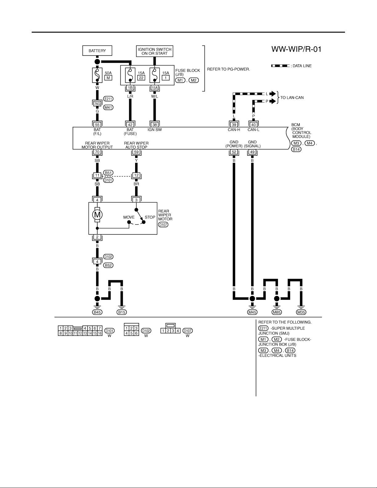
Wiring Diagram - WIP/ R -
INFOID:0000000001328578
TKWM4376E
WW-32
Page 33
REAR WIPER AND WASHER SYSTEM
Revision: 2007 April
2008 FX35/FX45
< SERVICE INFORMATION >
A
B
C
D
E
F
G
H
I
J
WW
L
M
N
O
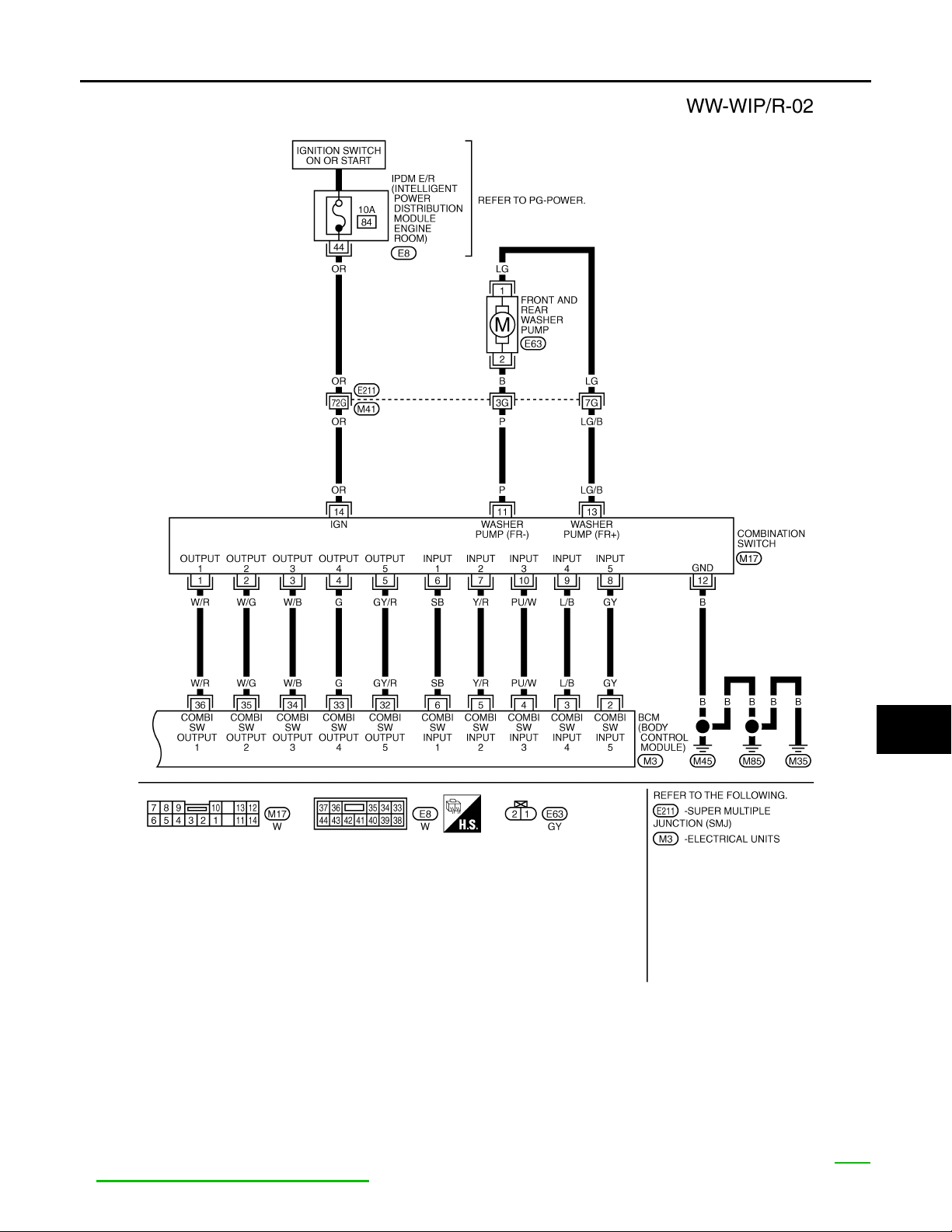
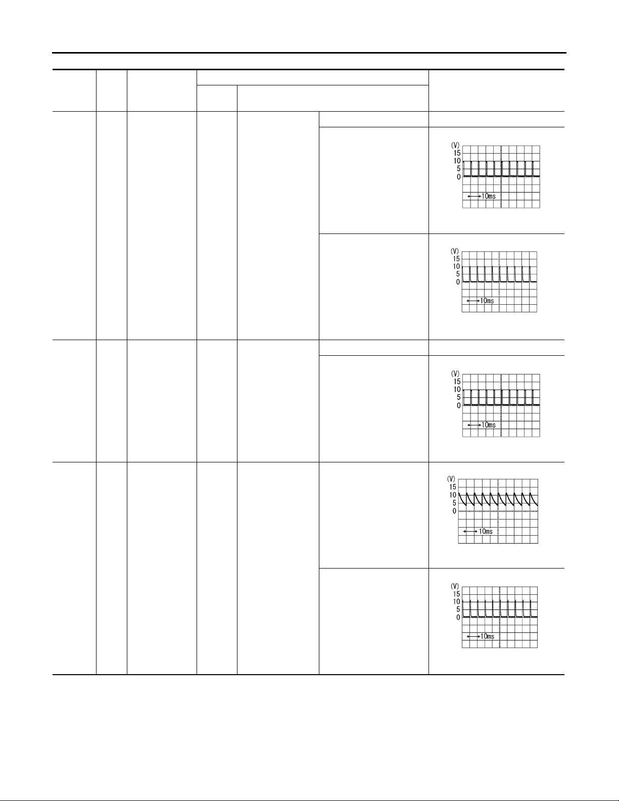
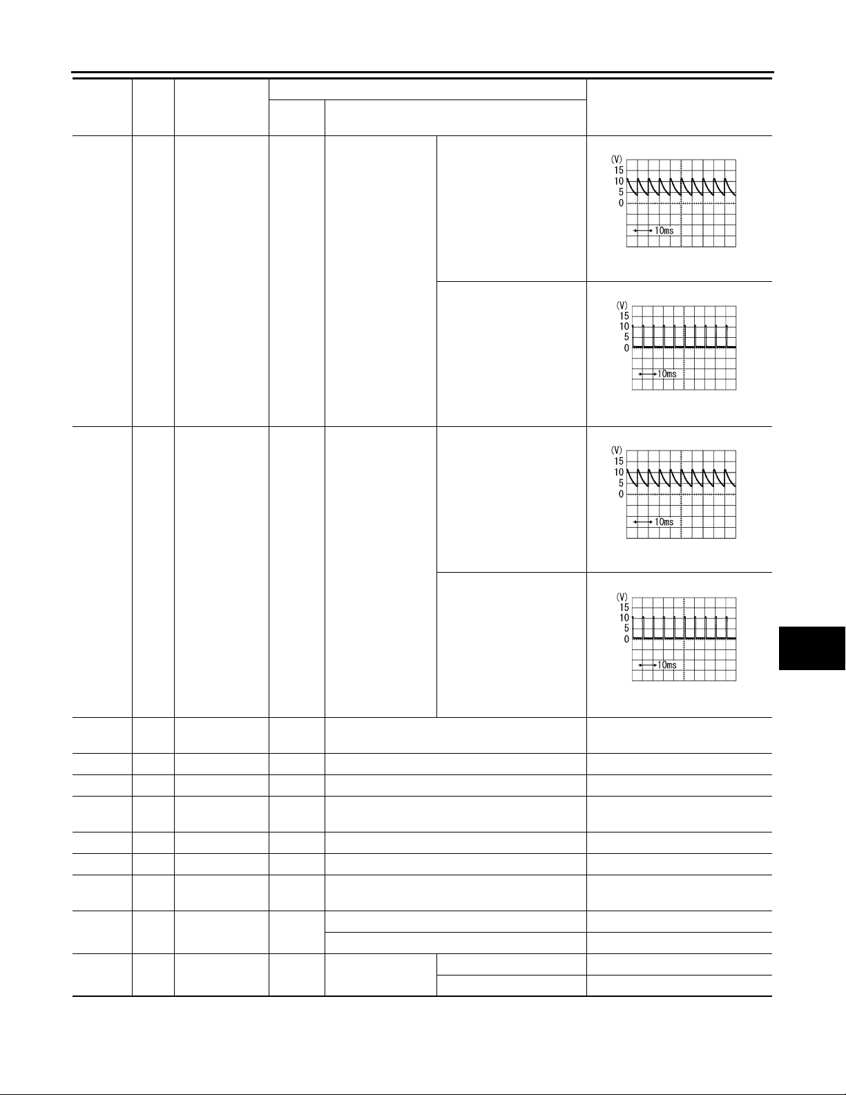
Terminal and Reference Value for BCM INFOID:0000000001328579
CAUTION:
• Check combination switch system terminal waveform under the loaded condition with lighting
switch, turn signal switch and wiper switch OFF not to be fluctuated by overloaded.
• Turn wiper intermittent dial position to 4 except when checking waveform or voltage of wiper intermittent dial position. Wiper intermittent dial position can be confirmed on CONSULT-III. Refer to WW-
15, "CONSULT-III Functions (BCM)".
TKWM4377E
P
WW-33
Page 34
REAR WIPER AND WASHER SYSTEM
Revision: 2007 April
2008 FX35/FX45
< SERVICE INFORMATION >
Terminal
No.
Wire
color
5Y/R
Signal name
Combination
switch input 2
Ignition
switch
ON
Measuring condition
Operation or condition
Lighting, turn, wiper switch
(Wiper intermittent
dial position 4)
Reference value
OFF Approx. 0 V
Rear washer switch
PKIB4959J
Approx. 1.0 V
Rear wiper switch ON
PKIB4955J
Approx. 0.8 v
OFF Approx. 0 V
6SB
32 GY/R
Combination
switch input 1
Combination
switch output 5
ON
ON
Lighting, turn,
wiper switch
(Wiper intermittent
dial position 4)
Lighting, turn,
wiper switch
(Wiper intermittent
dial position 4)
Rear wiper INT
PKIB4959J
Approx. 1.0 V
OFF
PKIB4960J
Approx. 7.0 - 7.5 V
Rear wiper ON
PKIB4956J
Approx. 1.0 V
WW-34
Page 35
REAR WIPER AND WASHER SYSTEM
Revision: 2007 April
2008 FX35/FX45
< SERVICE INFORMATION >
Terminal
No.
33 G
Wire
color
Signal name
Combination
switch output 4
Ignition
switch
ON
Measuring condition
Operation or condition
Lighting, turn, wiper switch
(Wiper intermittent
dial position 4)
OFF
Rear wiper switch INT
OFF
Reference value
Approx. 7.2 V
Approx. 1.2 V
A
B
C
PKIB4960J
D
E
F
PKIB4958J
G
H
Lighting, turn, wip-
34 W/B
38 W/L
39 L CAN − H— — —
40 P CAN − L— — —
42 L/R
49 B Ground ON — Approx. 0 V
52 B Ground ON — Approx. 0 V
55 G
59 Y
70 SB
Combination
switch output 3
Ignition switch
(ON)
Battery power
supply
Battery power
supply
Rear wiper auto
stop signal
Rear wiper motor output signal
ON
ON — Battery voltage
OFF — Battery voltage
OFF — Battery voltage
ON
ON Wiper switch
er switch
(Wiper intermittent
dial position 4)
Rear washer switch
Wiper operating Approx. 0 V
Wiper stopped Battery voltage
OFF Approx. 0 V
ON Battery voltage
Approx. 7.2 V
Approx. 1.2 V
PKIB4960J
PKIB4958J
I
J
WW
L
M
N
O
P
How to Proceed with Trouble Diagnosis INFOID:0000000001328580
1. Confirm the symptoms and customer complaint.
WW-35
Page 36
REAR WIPER AND WASHER SYSTEM
Revision: 2007 April
2008 FX35/FX45
< SERVICE INFORMATION >
2. Understand operation description and function description. Refer to WW-30, "System Description".
3. Perform the Preliminary Check. Refer to WW-36, "
Preliminary Check".
4. Check symptom and repair or replace the cause of malfunction.
5. Does the rear wiper and washer operate normally? If YES, GO TO 6. If NO, GO TO 4.
6. INSPECTION END
Preliminary Check INFOID:0000000001328581
CHECK POWER SUPPLY AND GROUND CIRCUIT
1.CHECK FUSES
Check for blown fuses.
Unit Power source Fuse and fusible link No.
M
22
BCM
Front and rear washer pump Ignition ON or START 84
Refer to WW-32, "Wiring Diagram - WIP/ R -".
Battery
Ignition ON or START 1
OK or NG
OK >> GO TO 2.
NG >> If fuse is blown, be sure to eliminate cause of malfunction before installing new fuse, Refer to PG-
3, "Schematic".
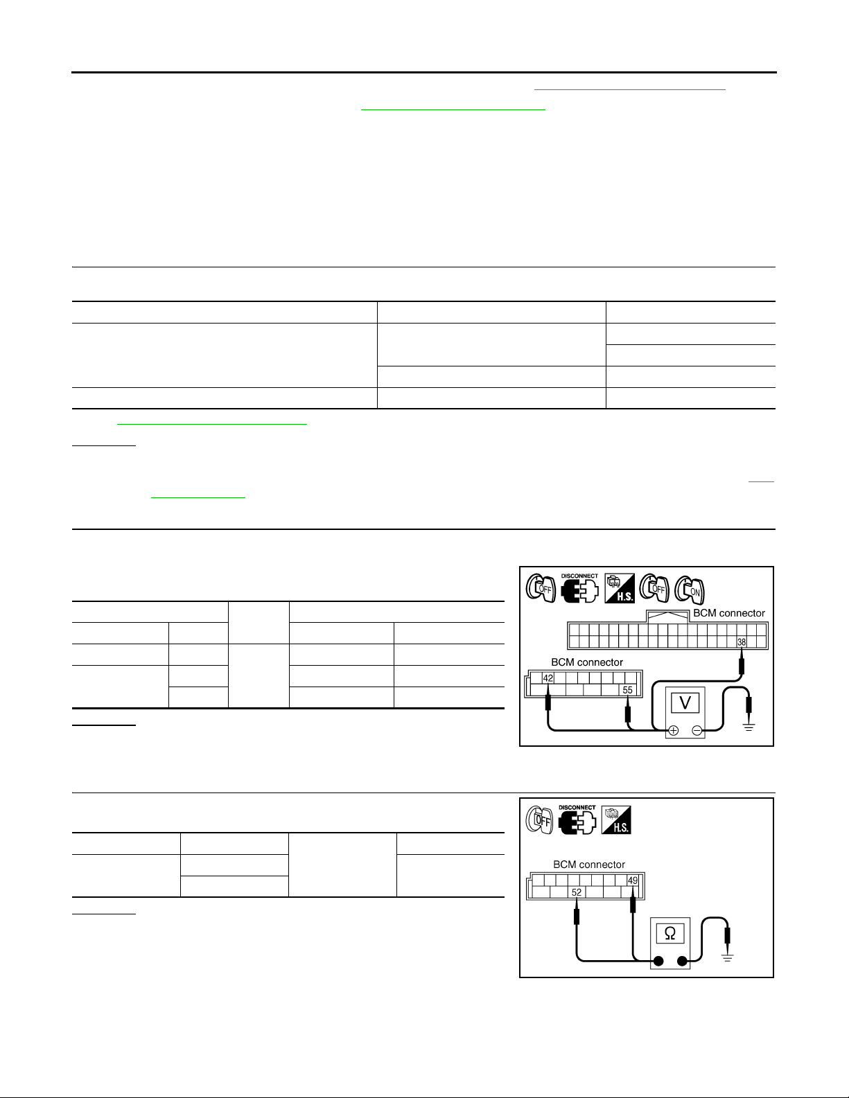
2.CHECK POWER SUPPLY CIRCUIT
1. Turn ignition switch OFF.
2. Disconnect BCM connector.
3. Check voltage between BCM harness connector and ground.
(+)
BCM connector Terminal OFF ON
M3 38
M4
42 Battery voltage Battery voltage
55 Battery voltage Battery voltage
(-)
Ground
Ignition switch position
Approx. 0 V Battery voltage
OK or NG
OK >> GO TO 3.
NG >> Repair harness or connector.
3.CHECK GROUND CIRCUIT
Check continuity between BCM harness connector and ground.
BCM connector Termin al
M4
49
52
OK or NG
OK >> INSPECTION END
NG >> Repair harness or connector.
Ground
Continuity
Yes
PKIA7520E
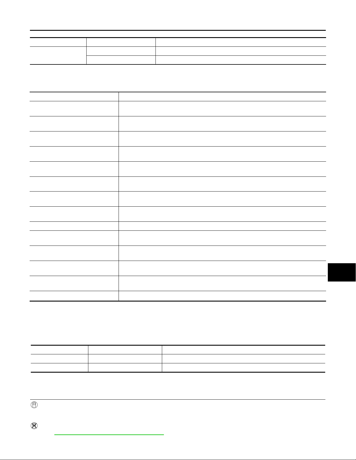
CONSULT-III Functions (BCM) INFOID:0000000001328582
CONSULT-III can display each diagnostic item using the diagnostic test mode shown following.
SKIA5294E
WW-36
Page 37
REAR WIPER AND WASHER SYSTEM
Revision: 2007 April
2008 FX35/FX45
< SERVICE INFORMATION >
BCM diagnosis position Diagnosis mode Description
WIPER
DATA MONITOR Displays BCM input data in real time.
ACTIVE TEST Device operation can be checked by applying a drive signal to device.
DATA MONITOR
Display Item List
Monitor item Contents
IGN ON SW “ON/OFF”
IGN SW CAN “ON/OFF”
FR WIPER HI “ON/OFF”
FR WIPER LOW “ON/OFF”
FR WIPER INT “ON/OFF”
FR WASHER SW “ON/OFF”
INT VOLUME “1 - 7”
FR WIPER STOP “ON/OFF”
VEHICLE SPEED “km/h” Displays status vehicle speed as judged from vehicle speed signal.
RR WIPER ON “OFF ”
RR WIPER INT “OFF”
RR WASHER SW “OFF”
RR WIPER STOP “OFF”
H/L WASH SW
NOTE:
This item is displayed, but cannot be monitored.
NOTE
“ON/OFF” —
Displays status (ignition switch IGN position: ON/other: OFF) of ignition switch judged from the
ignition switch signal.
Displays status (ignition switch IGN position: ON/other: OFF) of ignition switch judged from the
ignition switch signal (CAN communication lines).
Displays status (front wiper switch high position: ON/other: OFF) of front wiper high switch
judged from the front wiper switch signal.
Displays status (front wiper switch low position: ON/other: OFF) of front wiper low switch
judged from the front wiper switch signal.
Displays status (front wiper switch intermi ttent position: ON/other: OFF) of front wiper intermittent switch judged from the front wiper switch signal.
Displays status (front washer switch ON position: ON/other: OFF) of front washer switch
judged from the front wiper switch signal.
Displays status (wiper intermittent dial position setting 1- 7) of intermittent volume switch
judged from the front wiper switch signal.
Displays status (front wiper stop position: ON/move: OFF) of front wiper motor stop judged
from the front wiper auto stop signal .
Displays status (rear wiper switch ON position: ON/other: OFF) of rear wiper switch judged
from the rear wiper switch signal.
Displays status (rear wiper switch intermittent position: ON/other: OFF) of rear wiper intermittent switch judged from the rear wiper switch si gnal.
Displays status (rear washer switch ON po sition: ON/other: OFF) of rear washer swi tch judged
from the rear wiper switch signal.
Displays status (rear wiper stop position: OFF/move: ON) of rear wiper motor stop judged from
the rear wiper auto stop signal.
ACTIVE TEST
A
B
C
D
E
F
G
H
I
J
WW
L
M
Display Item List
Front wiper output FR WIPER With a certain operation (OFF, HI, LO, INT), front wiper can be operated.
Rear wiper output RR WIPER Rear wiper can be operated by any ON-OFF operation
Rear Wiper Does Not Operate INFOID:0000000001328583
1.CHECK CIRCUIT BETWEEN COMBINATION SWITCH AND BCM
With CONSULT-III
1. Select “RR WIPER ON” of BCM data monitor item.
2. With operating the wiper switch, check the monitor status.
Without CONSULT-III
Refer to LT-104, "
N
T est item Display on CONSULT-III screen Description
O
P
Combination Switch Inspection".
WW-37
Page 38
REAR WIPER AND WASHER SYSTEM
Revision: 2007 April
2008 FX35/FX45
< SERVICE INFORMATION >
OK or NG
OK >> GO TO 2.
NG >> Check combination switch (wiper switch). Refer to LT-104, "
Combination Switch Inspection".
2.ACTIVE TEST
With CONSULT-III
1. Select “REAR WIPER” of BCM active test item.
2. With operating the test item, check the rear wiper operation.
Without CONSULT-III
GO TO 3.
Does rear wiper operate normally?
YES >> Replace BCM. Refer to BCS-13, "Removal and Installation of BCM".
NO >> GO TO 3.
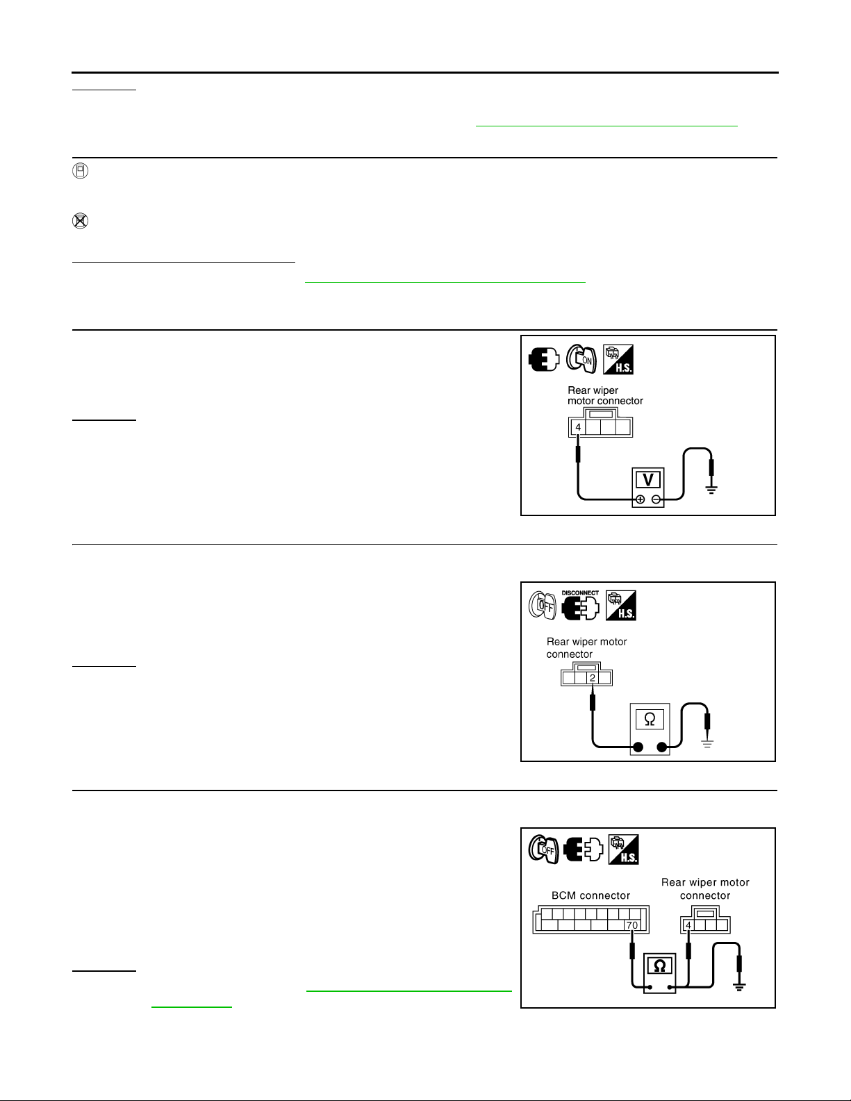
3.CHECK BCM
With rear wiper switch ON, check voltage between rear wiper motor
harness connector and ground.
4 – Ground : Battery voltage.
OK or NG
OK >> GO TO 4.
NG >> GO TO 5.
4.CHECK GROUND CIRCUIT
1. Turn ignition switch OFF.
2. Disconnect rear wiper motor connector.
3. Check continuity between rear wiper motor harness connector
and ground.
2 – Ground : Continuity should exist.
OK or NG
OK >> Replace rear wiper motor.
NG >> Repair harness or connector.
5.CHECK REAR WIPER CIRCUIT
1. Turn ignition switch OFF.
2. Disconnect BCM connector and rear wiper motor connector.
3. Check continuity between BCM harness connector and rear
wiper motor harness connector.
70 – 4 : Continuity should exist.
4. Check continuity between BCM harness connector and ground.
PKIB1784E
PKIA5200E
OK or NG
OK >> Replace BCM. Refer to BCS-13, "Removal and Installa-
NG >> Repair harness or connector.
70 – Ground : Continuity sh ould not exi st.
tion of BCM".
WW-38
PKID0795E
Page 39
REAR WIPER AND WASHER SYSTEM
Revision: 2007 April
2008 FX35/FX45
< SERVICE INFORMATION >
Rear Wiper Does Not Return to Stop Position INFOID:0000000001328584
1.CHECK REAR WIPER MOTOR CIRCUIT
A
With CONSULT-III
1. Select “RR WIPER STOP” of BCM data monitor item.
2. Check that “RR WIPER STOP”, turn ON-OFF linked with rear wiper switch operation.
Without CONSULT-III
GO TO 2.
OK or NG
OK >> Replace BCM. Refer to BCS-13, "Removal and Installation of BCM".
NG >> GO TO 2.
2.CHECK REAR WIPER AUTO STOP CIRCUIT
1. Turn ignition switch OFF.
2. Disconnect BCM connector and rear wiper motor connector.
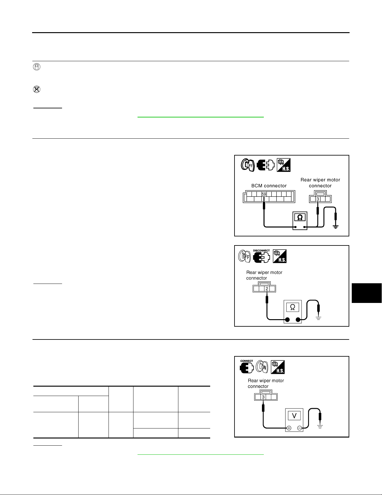
3. Check continuity between BCM harness connector and rear
wiper motor harness connector.
59 – 3 : Continuity should exist.
4. Check continuity between BCM harness connector and ground.
59 – Ground : Continuity should not exist.
5. Check continuity between rear wiper motor harness connector
and ground.
B
C
D
E
F
G
H
PKID0796E
I
2 – Ground : Continuity should exist.
OK or NG
OK >> GO TO 3.
NG >> Repair harness or connector.
3.CHECK REAR WIPER MOTOR SIGNAL
1. Connect BCM connector and rear wiper motor connector.
2. Turn ignition switch ON.
3. Check voltage between rear wiper motor harness connector and
ground while rear wiper motor is stopped and while it is operating.
(+)
Rear wiper motor
Connector
D107 3 Ground
Terminal
(-) Condition
Wiper stopped
Wiper operating 0 V
OK or NG
OK >> Replace BCM. Refer to BCS-13, "Removal and Installation of BCM".
NG >> Replace rear wiper motor.
Voltage
(Approx.)
Battery
voltage
PKIA5200E
PKIA5203E
J
WW
L
M
N
O
P
WW-39
Page 40
REAR WIPER AND WASHER SYSTEM
Revision: 2007 April
2008 FX35/FX45
< SERVICE INFORMATION >
Only Rear Wiper ON Does Not Operate
Refer to LT-104, "Combination Switch Inspection".
INFOID:0000000001328585
Only Rear Wiper INT Does Not Operate INFOID:0000000001328586
Refer to LT-104, "Combination Switch Inspection".
Wiper Does Not Wipe When Rear Washer Operates INFOID:0000000001328587
Refer to LT-104, "Combination Switch Inspection".
Rear Wipers Do Not Stop INFOID:0000000001328588
1.CHECK CIRCUIT BETWEEN COMBINATION SWITCH AND BCM
With CONSULT-III
1. Select “RR WIPER INT”, “RR WIPER ON”, and “RR WASHER SW” of BCM data monitor item.
2. With operating the wiper switch, check the monitor status.
Without CONSULT-III
Refer to LT-104, "
OK or NG
OK >> Replace BCM. Refer to BCS-13, "Removal and Installation of BCM".
NG >> Check combination switch (wiper switch). Refer to LT-104, "
Removal and Installation of Rear Wiper Arm, Adjustment of Wiper Arms S top Location
Combination Switch Inspection".
Combination Switch Inspection".
INFOID:0000000001328589
REMOVA L
1. Turn rear wiper switch ON to operate wiper motor, then turn rear wiper switch OFF (auto stop).
2. Remove rear wiper arm cap, and remove rear wiper arm nut.
3. Remove rear wiper arm from the vehicle.
INSTALLATION
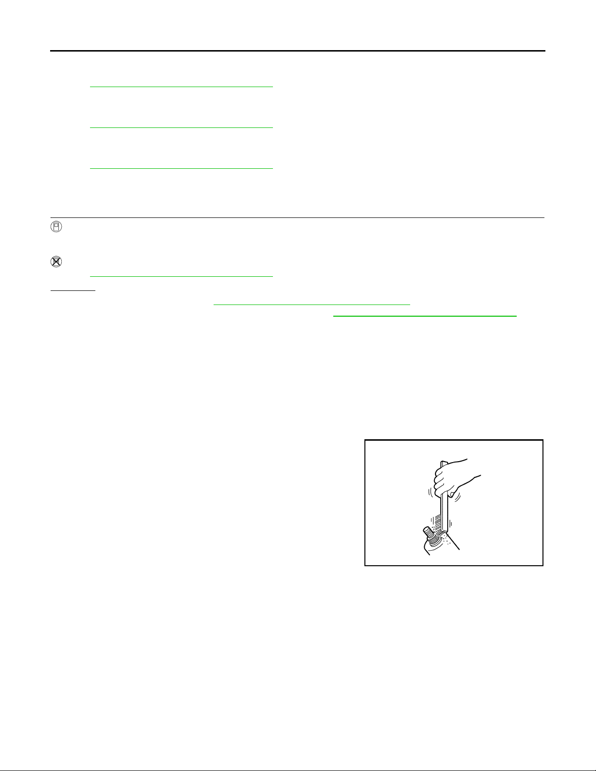
1. Clean up the pivot area as shown in the figure. This will reduce
possibility of rear wiper arm nuts looseness.
2. Prior to rear wiper arms installation, turn rear wiper switch ON to
operate wiper motor, and then turn rear wiper switch OFF (auto
stop).
SKIA0082J
WW-40
Page 41
REAR WIPER AND WASHER SYSTEM
Revision: 2007 April
2008 FX35/FX45
< SERVICE INFORMATION >
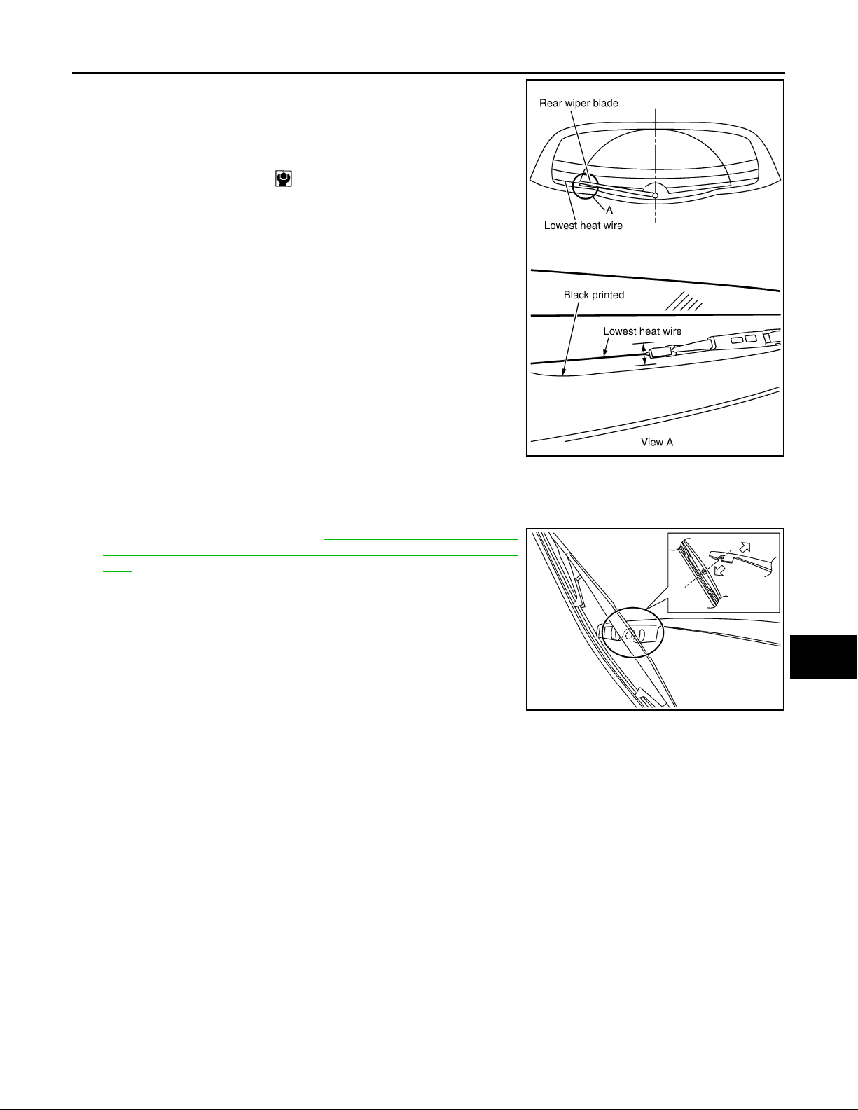
3. Lift the blade up and then set it down onto back door window
glass surface to set the blade center to lowest heat wire immediately.
4. Tighten rear wiper arm nuts to specified torque.
Rear wiper arm nut : 8.8 N·m (0.90 kg-m, 78 in-lb)
A
B
5. Spray washer fluid. Turn on rear wiper switch ON to operate
wiper motor, and then turn rear wiper switch OFF (auto stop).
6. Ensure that wiper blade stop within the following range.
Lowest heat wire : ± 3.75 mm (± 0.148 in)
7. Install rear wiper arm cap.
PKID0496E
Removal and Installation of Rear Wiper Blade INFOID:0000000001328590
REMOVA L
1. Remove rear wiper arm. Refer to WW-40, "Removal and Instal-
lation of Rear Wiper Arm, Adjustment of Wiper Arms Stop Location".
2. Turn rear wiper blade 90 degrees against rear wiper arm, and
pull it out downward for removal.
CAUTION:
Replace rear wiper blade as rear wiper blade assembly.
C
D
E
F
G
H
I
J
WW
INSTALLATION
Installation is the reverse order of removal.
WW-41
SKIA6169E
L
M
N
O
P
Page 42
REAR WIPER AND WASHER SYSTEM
Revision: 2007 April
2008 FX35/FX45
< SERVICE INFORMATION >
Removal and Installation of Rear Wiper Motor
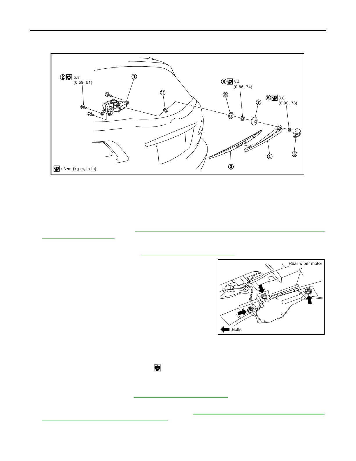
1. Rear wiper motor 2. Rear wiper mounting bolts 3. Rear wiper blade
4. Rear wiper arm 5. Rear wiper arm cap 6. Rear wiper arm nut
7. Pivot cap 8. Nut 9. Washer
10. Cushion rubber
INFOID:0000000001328591
SKIB7578E
REMOVA L
1. Remove rear wiper arm. Refer to WW-40, "Removal and Installation of Rear Wiper Arm, Adjustment of
Wiper Arms Stop Location".
2. Remove pivot cap, and remove nut from vehicle.
3. Remove back door finisher. Refer to EI-47, "
Component Parts Location".
4. Disconnect rear wiper motor connector.
5. Remove rear wiper motor mounting bolts and remove rear wiper
motor from vehicle.
CAUTION:
Never remove cushion rubber.
PKIB3588E
INSTALLATION
1. Install rear wiper motor to the vehicle.
Rear wiper motor mounting bolts : 5.8 N·m (0.59 kg-m, 51 in-lb)
2. Connect rear wiper motor connector. Turn rear wiper switch ON to operate rear wiper motor, and then turn
rear wiper switch OFF (auto stop).
3. Install back door finisher. Refer to EI-47, "
4. Install pivot cap, and nut.
5. Install rear wiper arm and rear wiper arm caps. Refer to WW-40, "
Arm, Adjustment of Wiper Arms Stop Location".
CAUTION:
Never drop the wiper motor or cause it to contact other parts.
Component Parts Location".
Removal and Installation of Rear Wiper
WW-42
Page 43
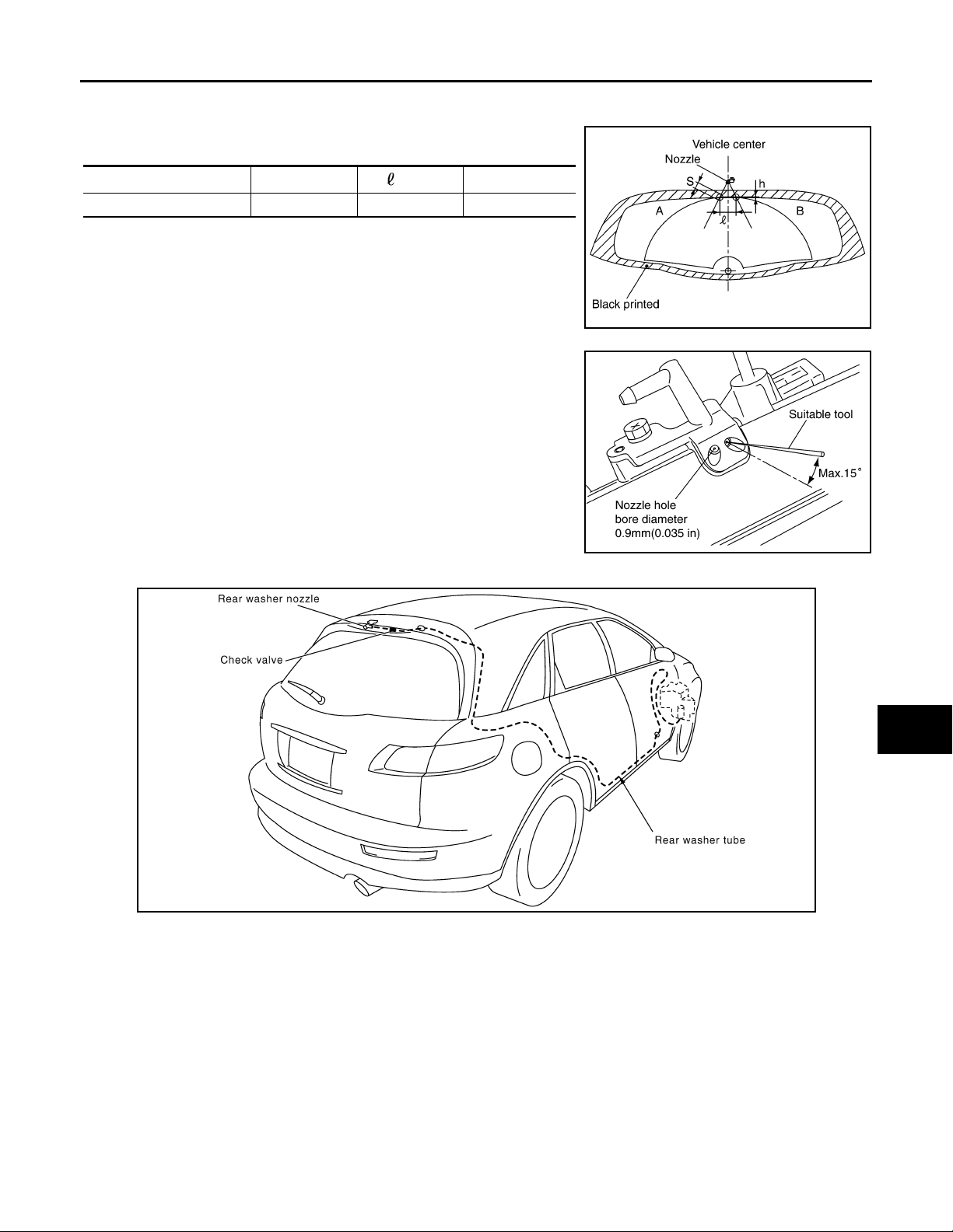
REAR WIPER AND WASHER SYSTEM
Revision: 2007 April
2008 FX35/FX45
< SERVICE INFORMATION >
Washer Nozzle Adjustment INFOID:0000000001328592
• Adjust spray positions as shown in the figure.
Unit: mm (in)
Spray position h (height)
A, B 2.5 (0.0 98 ) 8 0 (3.1 5) 30 (1.18)
(width)
φS
SKIA5088E
A
B
C
D
• Insert a needle or suitable tool into the nozzle hole and move it to
adjust the spray position.
Adjustable range : ± 15° (In any direction)
SKIA5087E
Washer Tube Layout INFOID:0000000001328593
E
F
G
H
I
J
WW
L
Removal and Installation of Washer Nozzle INFOID:0000000001328594
REMOVA L
M
PKIC9709E
N
O
P
WW-43
Page 44
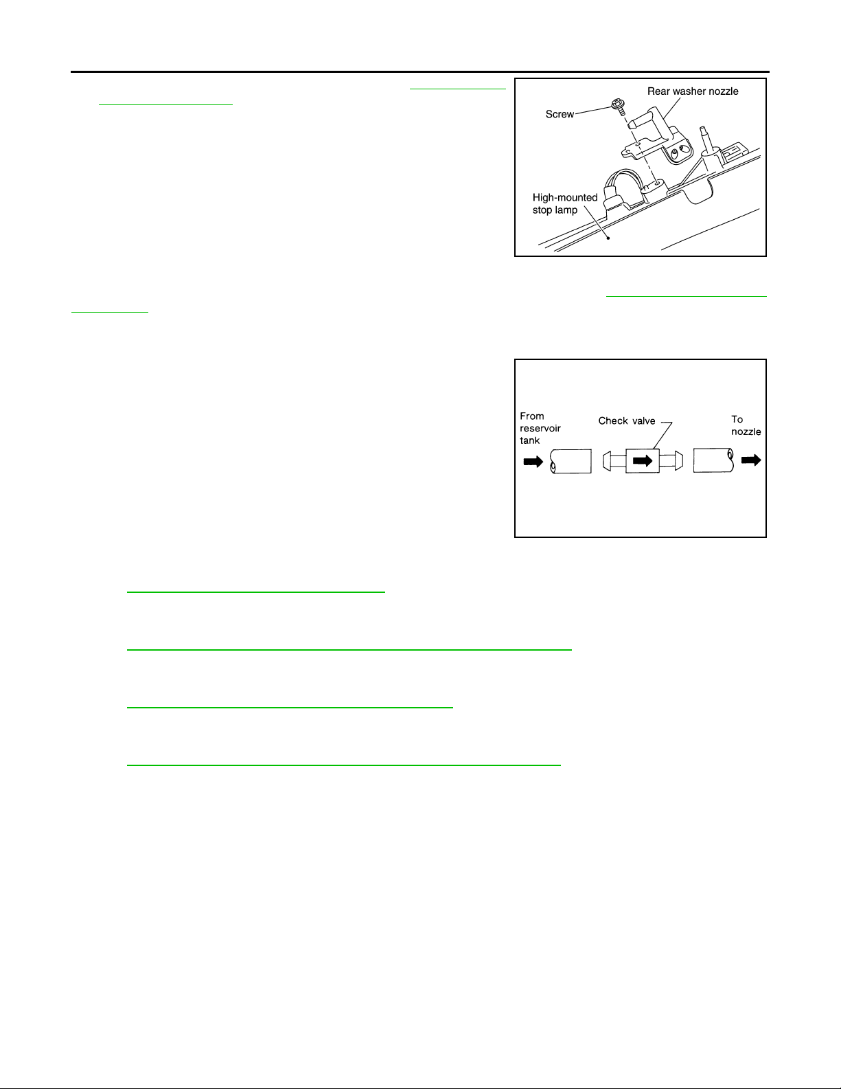
REAR WIPER AND WASHER SYSTEM
Revision: 2007 April
2008 FX35/FX45
< SERVICE INFORMATION >
1. Remove high-mounted stop lamp. Refer to LT-114, "High-
Mounted Stop Lamp".
2. Remove screw and remove washer nozzle from high-mounted
stop lamp.
PKIB6132E
INSTALLATION
Installation is the reverse order of removal. Adjust nozzle spray location. Refer to WW-43, "Washer Nozzle
Adjustment".
Check Valve INFOID:0000000001328595
Blow check valve. Confirm that the air ventilates. Also confirm that
inhalation is impossible.
CAUTION:
A check valve is provided in the washer fluid line. Be careful not
to connect check valve to washer tube in the wrong direction.
SEL411H
Inspection of Front Wiper and Washer Switch Circuit INFOID:0000000001328596
Refer to LT-104, "Combination Switch Inspection".
Removal and Installation of Rear Wiper and Washer Switch INFOID:0000000001328597
Refer to WW-28, "Removal and Installation of Front Wiper and Washer Switch".
Removal and Installation of Washer Tank INFOID:0000000001328598
Refer to WW-28, "Removal and Installation of Washer Tank".
Removal and Installation of Front and Rear Washer pump INFOID:0000000001328599
Refer to WW-29, "Removal and Installation of Front and Rear Washer Pump".
WW-44
Page 45
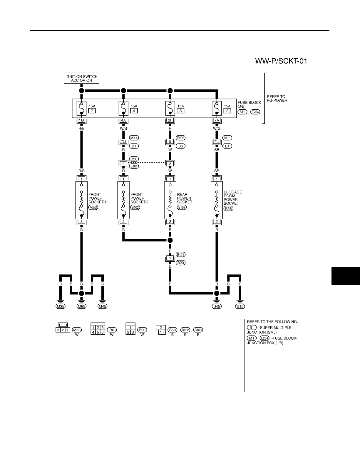
< SERVICE INFORMATION >
Revision: 2007 April
2008 FX35/FX45
POWER SOCKET
POWER SOCKET
Wiring Diagram - P/SCKT - INFOID:0000000001328600
A
B
C
D
E
F
G
H
TKWM4490E
I
J
WW
L
M
N
O
P
Removal and Installation of Front Power Socket - 1 INFOID:0000000001328601
REMOVA L
WW-45
Page 46
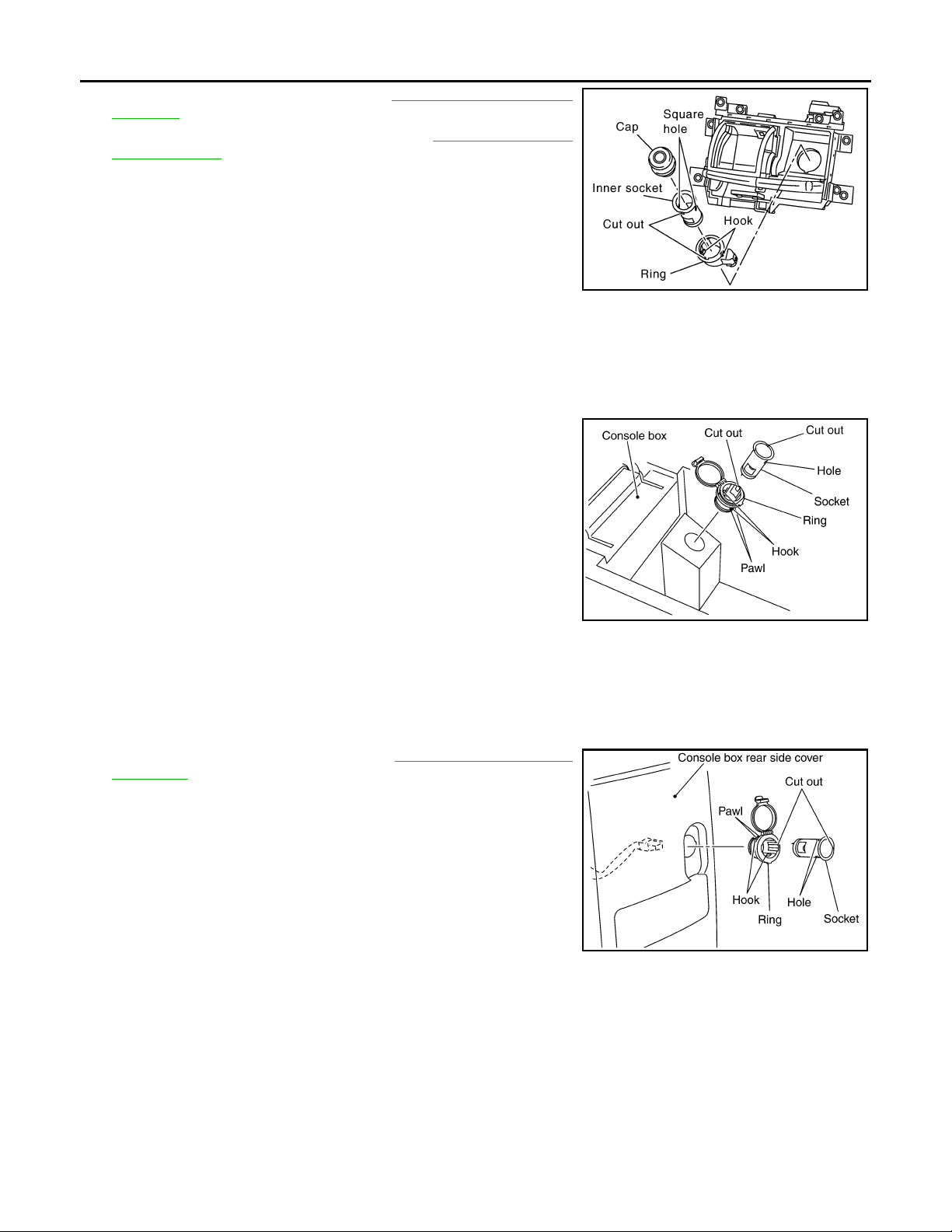
POWER SOCKET
Revision: 2007 April
2008 FX35/FX45
< SERVICE INFORMATION >
1. Remove A/T console finisher. Refer to IP-10, "Component Parts
Location".
2. Remove instrument clock finisher. Refer to IP-10, "
Parts Location".
3. Disconnect power socket connector.
4. Remove inner socket from the ring while pressing the hook on
the ring out from square hole.
5. Remove ring from ashtray while pressing pawls.
Component
PKIC9710E
INSTALLATION
Installation is the reverse order of removal.
Removal and Installation of Front Power Socket - 2 INFOID:0000000001328602
REMOVA L
1. Remove inner socket from the ring. While pressing the hook on
the ring out from square hole.
2. Remove ring from power socket finisher while pressing pawls.
3. Disconnect power socket connector.
SKIA5096E
INSTALLATION
Installation is the reverse order of removal.
Removal and Installation of Rear Power Socket INFOID:0000000001328603
REMOVA L
1. Remove console rear finisher. Refer to IP-16, "Disassembly and
Assembly".
2. Disconnect power socket connector.
3. Remove inner socket from the ring. While pressing the hook on
the ring out from square hole.
4. Remove ring from power socket finisher while pressing pawls.
SKIA5094E
INSTALLATION
Installation is the reverse order of removal.
Removal and Installation of Luggage Room Power Socket INFOID:0000000001328604
REMOVA L
WW-46
Page 47
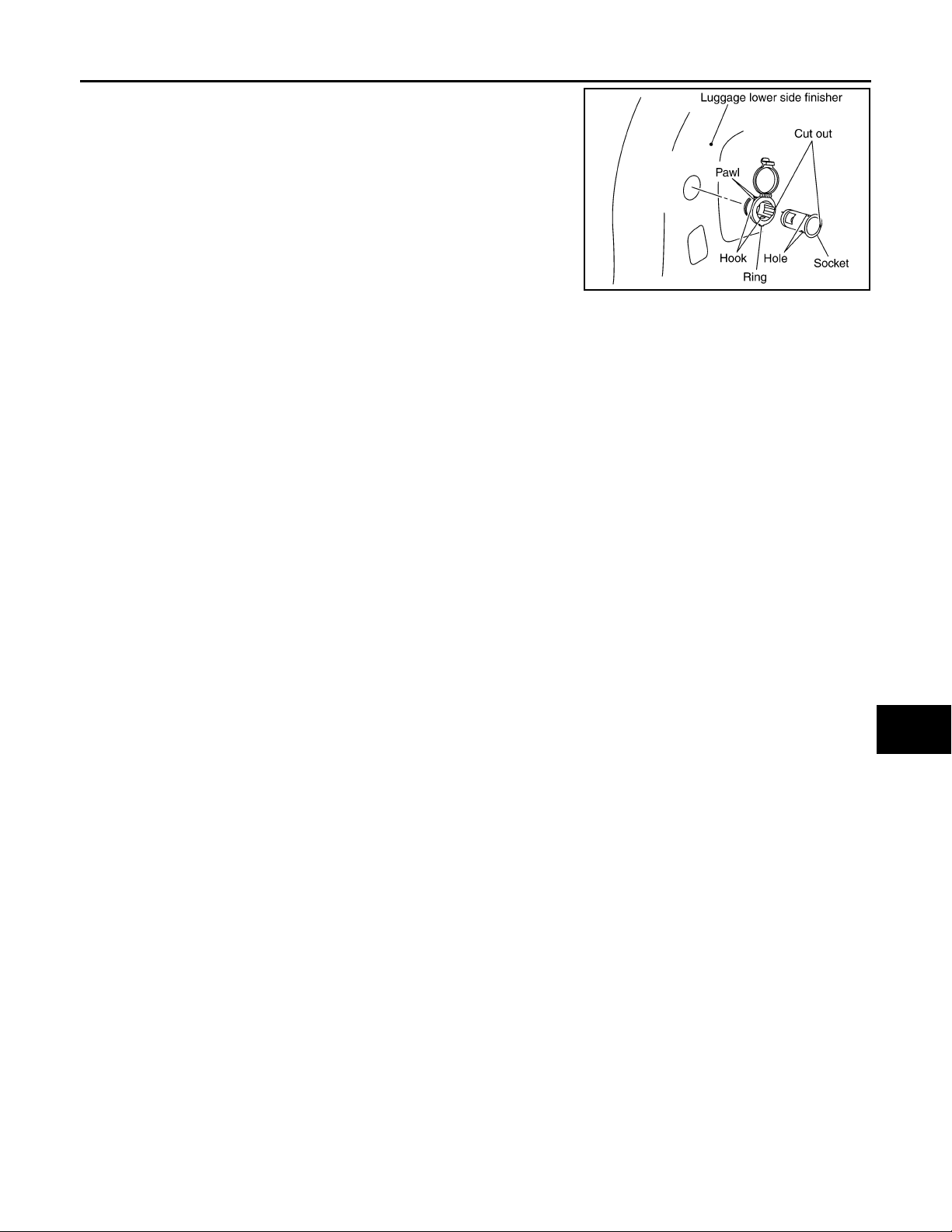
POWER SOCKET
Revision: 2007 April
2008 FX35/FX45
< SERVICE INFORMATION >
1. Remove inner socket from the ring. While pressing the hook on
the ring out from square hole.
2. Remove ring from power socket finisher while pressing pawls.
3. Disconnect power socket connector.
INSTALLATION
Installation is the reverse order of removal.
A
B
C
SKIA5097E
D
E
F
G
H
I
J
WW
L
M
N
O
P
WW-47
Page 48
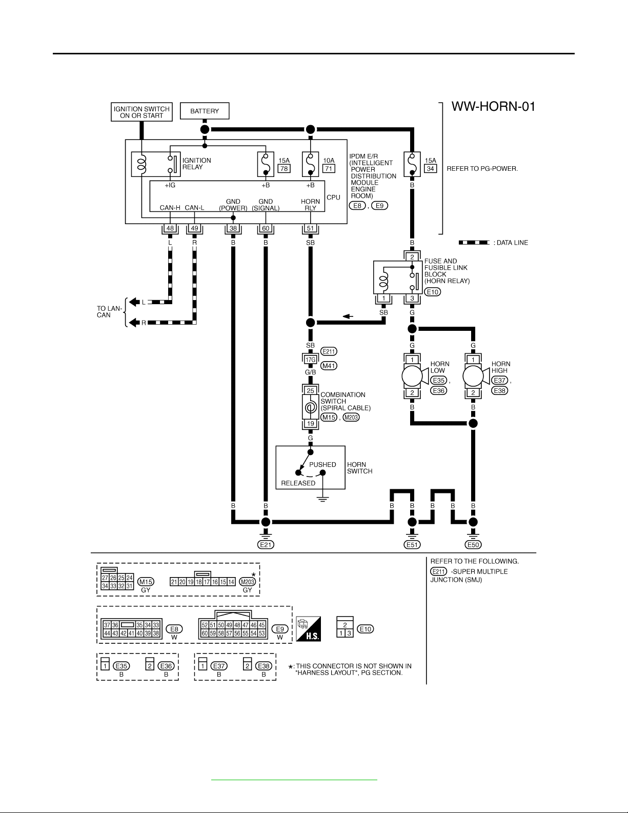
HORN
Revision: 2007 April
2008 FX35/FX45
< SERVICE INFORMATION >
HORN
Wiring Diagram - HORN - INFOID:0000000001328605
Removal and Installation INFOID:0000000001328606
REMOVA L
1. Remove front grille. Refer to EI-22, "Component Parts Location".
TKWM4378E
WW-48
Page 49
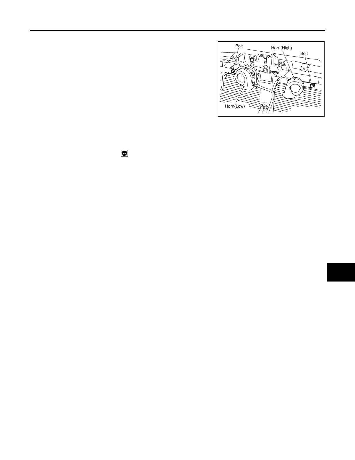
HORN
Revision: 2007 April
2008 FX35/FX45
< SERVICE INFORMATION >
2. Disconnect all horn connectors.
3. Remove horn mounting bolt and remove horn from vehicle.
A
B
C
INSTALLATION
Installation is the reverse order of removal.
• Tighten horn bolt to specified torque.
Horn mounting bolt : 5.8 N·m (0.59 kg-m, 51 in-lb)
SKIA5093E
D
E
F
G
H
I
J
WW
L
M
N
O
P
WW-49
 Loading...