

WT8076
Passive Infrared (PIR) Controller
Version 1.0 25-May-1995
Weltrend Semiconductor, Inc. All Rights Reserved
偉詮電子股份有限公司
1
Weltrend Semiconductor Inc.
新竹市科學工業園區工業東九路 24 號 2 樓
2F, No. 24, Industry E. 9th RD., Science-Based Industrial Park, Hsin-Chu, Taiwan
TEL:886-3-5780241 FAX:886-3-5794278.5770419
eltrend
GENERAL DESCRIPTION
The WT8076 is a PIR controller IC which integrates amplifier, window detector and light control
functions. The light can be controlled by a Relay or Triac with adjustable delay time. A CDS interface is
provided to sense day time and night time. A walk-test fuction helps user while setting up the light set.
The line remote control function can switch the light set between auto mode and always-on mode.
FEATURES
• Adjustable detection range
• Adjustable delay time
• CDS interface to differentiate night time and day time
• Walk-test function
• Line remote control to switch auto mode and always on mode
• Relay or Triac output
• High noise immunity
• Low power consumption ( operating 500uA, standby 130uA, Typ. )
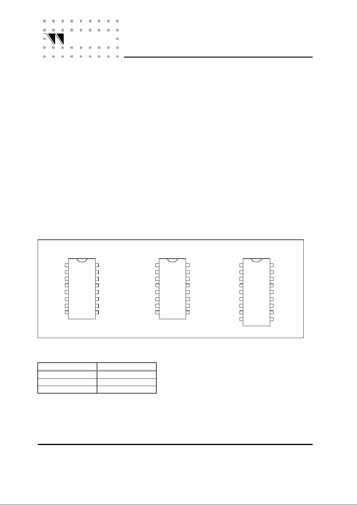
PIN ASSIGNMENT
UOU1
NII1
II1
VREF
GND
TB
TCI
UOU2
NII2
II2
CDS
VDD
ZCD
RELAY
TRIAC
1
2
3
4
5
6
7
8
16
15
14
13
12
11
10
9
1
2
3
4
5
6
7
8
16
15
14
13
12
11
10
9
GND
TB
TCI
TRIAC
RELAY
ZCD
VDD
VREF
II1
NII1
UOU1
UOU2
NII2
II2
CDS
UOU1
NII1
II1
VREF
GND
TB
TCI
UOU2
NII2
II2
CDS
VDD
ZCD
RELAYTRIAC
1
2
3
4
5
6
7
8
9
18
17
16
15
14
13
12
11
10
ND
WK
WT8076N16P1 WT8076S16P1 WT8076N18P2
Ordering Information
PART No. PACKAGE
WT8076N16P1 16 Pin P-DIP
WT8076S16P1 16 Pin SOIC
WT8076N18P2 18 Pin P-DIP

WT8076
Passive Infrared (PIR) Controller
Weltrend Semiconductor Inc.
2
eltrend
PIN DESCRIPTION
Pin No.
N16P1 S16P1 N18P1
Name Descriptions
1 13 1 UOU1 Output of the first stage OP amplifier.
2 14 2 NII1 Non-inverting input of the first stage OP amplifier.
3 15 3 II1 Inverting input of the first stage OP amplifier.
4 16 4 VREF Reference voltage output.
5 1 5 GND Ground.
6 2 6 TB Time Base. A RC oscillaror is connected on this pin.
Typical frequency is 30kHz.
7 3 7 --- No connection.
8 4 8 TCI Time control input. A RC oscillator is connected on this
pin. It controls the delay time of the light.
9 5 9 TRIAC Triac control pin. Active low.
10 6 10 RELAY Relay control pin. Active hight.
11 7 11 ZCD Zero-crossing input. It detects the zero-crossing point of
the AC line. The ouput of TRIAC pin is synchronous to this
pin.
* * 12 WKT Walk-Test function enable/disable. Internal pull low. The
walt-test function is disbled when this pin is high level.
* * 13 ND Night and day detection enable/disable. Internal pull low.
The night-and-day detection is disbled when this pin is
high level.
12 8 14 VDD Power supply.
13 9 15 CDS Connect a photo-sensitive resistor to detect night time
and day time. If the input level is lower than 1.2V, it is
day time. If the input level is higher than 1.9V, it is night
time.
14 10 16 II2 Inverting input of the second stage OP amplifier.
15 11 17 NII2 Non-inverting input of the second stage OP amplifier.
16 12 18 UOU2 Output of the second stage OP amplifier.
* WT8076N16P1 and WT8076S16P1 : Walk-Test and Night&Day function is always enabled.
WT8076
Passive Infrared (PIR) Controller
Weltrend Semiconductor Inc.
3
eltrend
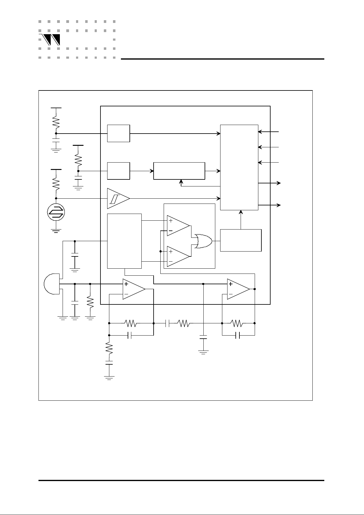
BLOCK DIAGRAM
1.25V
1.95V
OSC
OSC
CONTROL
LOGIC
Window
Detector
3.2V
REF.
VOLTAGE
UOU2II2UOU1II1
NII1
VREF
VDD
VDD
VDD
System Clock
WKT
ND
ZCD
RELAY
TRIAC
TB
TCI
CDS
NII2
PIR
CDS
WT8076 Block Diagram
1.6V
WT8076
Pulse Width
Detector
Counter

WT8076
Passive Infrared (PIR) Controller
Weltrend Semiconductor Inc.
4
eltrend
FUNCTIONAL DESCRIPTION
PIR Amplifier
The amplifier has two stages, please see block diagram . The voltage gain and frequency response can
be adjusted by the external resisters and capacitors.
Window Detector
If the amplified PIR signal is between VH (1.95V) and VL (1.25V), the signal is ignored and the output of
the window detector is low level. If the amplified signal is larger than VH or smaller than VL, the output of
the window detector is high level.
Pulse Width Detector
The pulse width detector detects the pulse width of the window detecter's output. If the pulse width is
less than 90ms ( fTB = 30kHz ), this pulse is ignored. If the pulse width is larger than 90ms, it will trigger
the light to turn on.
Light Control
The light is controlled by the RELAY pin or TRIAC pin. The RELAY pin outputs a high level when a valid
pulse is detected. The delay time is determined by the RC on the TCI pin. If another valid pulse
occurs during the delay time, the delay time will be reset. Fig. 1 shows the relationships.
The TRIAC pin is an open drain NMOS output. The turn on angle is about 24O .
1.95V
1.25V
UOU2 Pin
Signal on
<90ms >90ms >90ms >90ms<90ms
90ms
Window detector
output
RELAY pin
Pulse width
detector output
TRIAC pin
ZCD pin
Figure.1 Timing Relationship
delay time

WT8076
Passive Infrared (PIR) Controller
Weltrend Semiconductor Inc.
5
eltrend
CDS Interface
The CDS interface detects the level on the CDS pin. If the level is higher than 1.95V, it is night time.
If the level is lower than 1.25V, it is day time.
Operating Modes
The operating modes of WT8076 are:
(1) Auto mode:
The light will turn on when a valid pulse is detected in the night time.
(2) Always on mode:
If the ND pin is low level, the light is always on in the night time. When it detects day time, the
light will be turn off, and back to auto mode.
If the ND pin is high level, the light is always on.
(3) Walk-test mode:
The walk-test mode is active after the power is on. This mode is same as the auto mode except
the CDS is ignored. That is, the light will be turn on when a valid pulse is detected no matter it is
night time or day time.
Remote Control
To switch auto mode between always on mode, the WT8076 detects the zero crossings of the AC line. If
the line switch OFF and ON one time in 3 seconds, it toggles the auto mode and always on mode.
Time Base
The RC oscillator on the TB pin generates the system clock. The frequency is 30kHz typically (R
=30Kohm, C=1000pF) .
The following parameters are decided by the time base :
(1) Trigger angle of the TRIAC (24O , if time base is 30kHz).
(2) Pulse width (90ms,if time base is 30kHz).
(3) Remote control switch time.
(4) Disable PIR after the light is off.
(5) Total walk-test time.
The RC oscillator on the TCI pin sets the delay time. Figure 2 shows the relationship betwteen delay
time and the R ( C=1000pF).

WT8076
Passive Infrared (PIR) Controller
Weltrend Semiconductor Inc.
6
eltrend
ELECTRICAL CHARACTERISTICS
Absolute Maximum Ratings
Item Symbol Ratings Uit
supply voltage
VDD
6 V
Input Voltage
VIN
-0.5 to VDD+0.5 V
Operating Temperature
TOPR
-25 to 70
O
C
StorageTemperature
TSTG
-65 to 150
O
C
Power Dissipation
PD
500 mW
Note: Stress above those conditions listed may cause permente damage to the device.
Electrical Characteristics ( VDD=5.0V, TA=25
O
C )
Item Symbol Test Condition Min Typ Max Unit
Operating Voltage
VDD
4.5 5 5.5 V
Standby Current
IDDS
- 130 600 mA
Operating Current
IDDO
No load on output. - 500 1000 mA
Reference Voltage
VREF
3 3.2 3.4 V
Ripple of VREF - - 0.5 mV
Time Base Frequency
fTB
R=30K,C=1000p 28 30 32 kHz
CDS VT+
VT+
- 1.95 2.1 V
CDS VT-
VT+
1 1.25 - V
TCI Frequency
fTCI
- - 50k Hz
TRIAC pin Sink Current
IOL
VOL = 1.5V - - 15 mA
RELAY pin Source Current
IOH
VOH = 3.5V - - 5 mA
Characteristics of OP Amplifier ( VDD=5.0V, TA=25
O
C )
Item Symb
ol
Test Condition Min Typ Max Unit
Input Bias Current
Ibias
- - 10 nA
Input Offset Current
Ioffset
- - 10 nA
Input Offset Voltage
Voffset
- - 5 mV
Output Swing Voltage
Vswing
RL=470K 4 - - V
Output Source Current
Isource
7 - - uA
Output Sink Current
Isink
3.5 - - mA
Differential Gain
Av
- 100 - dB
Commom Mode Rejection Ration
CMRR
- 65 - dB
Power Supply Rejection Ration
PSRR
- 80 - dB

WT8076
Passive Infrared (PIR) Controller
Weltrend Semiconductor Inc.
7
eltrend
TYPICAL APPLICATION CIRCUIT
18 17 16 15 14 13 12 11 10
1 2 3 4 5 6 7 8 9
UOU1 NII1 II1 VREF GND TB TCI TRIAC
UOU2 NII2 II2 CDS VDD ND WKT ZCD RELAY
WT8076
560K
0.047u
Lamp
ZD1
12V
ZD2
5.6V
220u
25V
2.4K
1M470K
100u
10V
R10
R11
R9
D1
1N4001
C11
C10
C12
R12
47
0.47u/250V
R13
100
0.047u
250V
C13
AC
110V
R5
820K
R4
15K
C5
33u
C6
0.1u
C3
100u
C1
1000p
C2
R1R2
30K 20K
1000p
R3
47K
C4
0.01u
PIR
R7
R6
C9
C8
C7
47u
15K47u
CDS
R8
51K
RELAY
R14
5.6K
WT8076N18P1 Application Circuit For RELAY Output
L
N
FUSE
D3
1N4148
Note:
(1) To adjust delay time, change R1 value. ( R1=20K, delay time is about 10 sec )
(2) For different CDS, R8 value should be adjusted.

WT8076
Passive Infrared (PIR) Controller
Weltrend Semiconductor Inc.
8
eltrend
Note:
(1) To adjust delay time, change R1 value. ( R1=20K, delay time is about 10 sec )
(2) For different CDS, R8 value should be adjusted.
18 17 16 15 14 13 12 11 10
1 2 3 4 5 6 7 8 9
UOU1 NII1 II1 VREF GND TB TCI TRIAC
UOU2 NII2 II2 CDS VDD ND WKT ZCD RELAY
WT8076
560K
0.047u
Lamp
ZD1
5.6V
1M470K
100u
10V
R10
R11
R9
D1
1N4004
C11
C10
R12
47
0.1u/250V
AC
110V
R5
820K
R4
15K
C5
33u
C6
0.1u
C3
100u
C1
1000p
C2
R1R2
30K 20K
1000p
R3
47K
C4
0.01u
PIR
R7
R6
C9
C8
C7
47u
15K47u
CDS
R8
51K
WT8076N18P1 Application Circuit For TRIAC Output
L
N
100K
TRIAC
R13
330
 Loading...