

Page 1

ROAD WHEELS & TIRES
E SUSPENSION
A
B
SECTION WT
CONTENTS
PRECAUTIONS .......................................................... 3
Precautions for Supplemental Rest raint System
(SRS) “AIR BAG” and “SEAT BELT PRE-TEN-
SIONER” .................................................................. 3
Precautions .............................................................. 3
Service Notice .......................................................... 4
PREPARATION ........................................................... 5
Special Service Tools ............................................... 5
Commercial Service Tools ........................................ 5
NOISE, VIBRATION AND HARSHNESS (NVH)
TROUBLESHOOTING .......................... ...................... 6
NVH Troubleshooting Chart ..................................... 6
LOW TIRE PRESSURE WARNING SYSTEM ............ 7
System Description .................................................. 7
DESCRIPTION ................................ ...................... 7
FUNCTION ...................................... ............. ......... 7
TRANSMITTER ........................ ............. ................ 7
ANTENNA .......................... ................................... 7
LOW TIRE PRESSURE WARNING CONTROL
UNIT ................................... ................................... 7
LOW TIRE PRESSURE WARNING LAMP AND
BUZZER ...................... .......................................... 8
TIRE PRESSURE WARNING CHECK SWITCH ..... 8
VEHICLE INFORMATION DISPLAY ..................... 8
System Diagram ....................................................... 9
COMPONENTS FUNCTION DESCRIPTION ....... 9
TROUBLE DIAGNOSIS ............................................ 10
How to Perform Trouble Diagnosis ........................ 10
BASIC CONCEPT ............................................... 10
INTRODUCTION ............................. ............. ....... 10
WORK FLOW .......................................................11
Component Parts Location ..................................... 12
Circuit Diagram ...................................................... 13
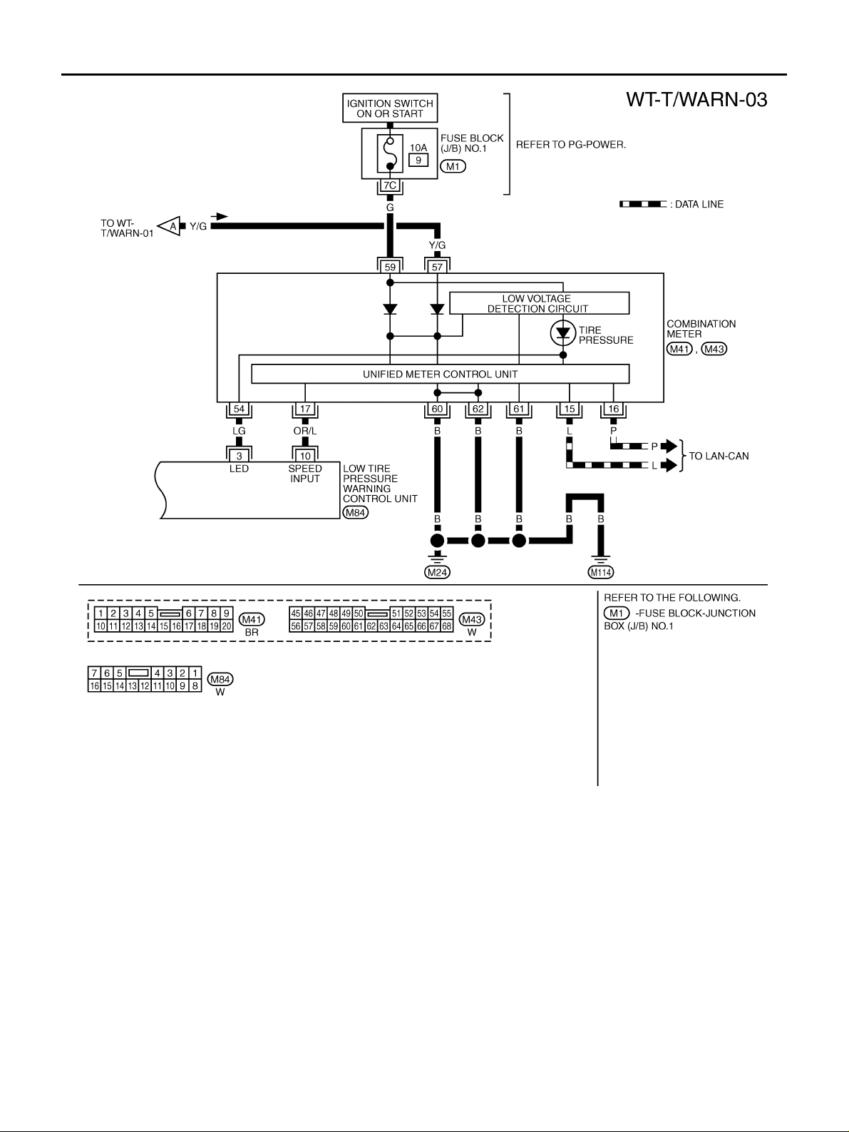
Wiring Diagram — T/WARN — .............................. 14
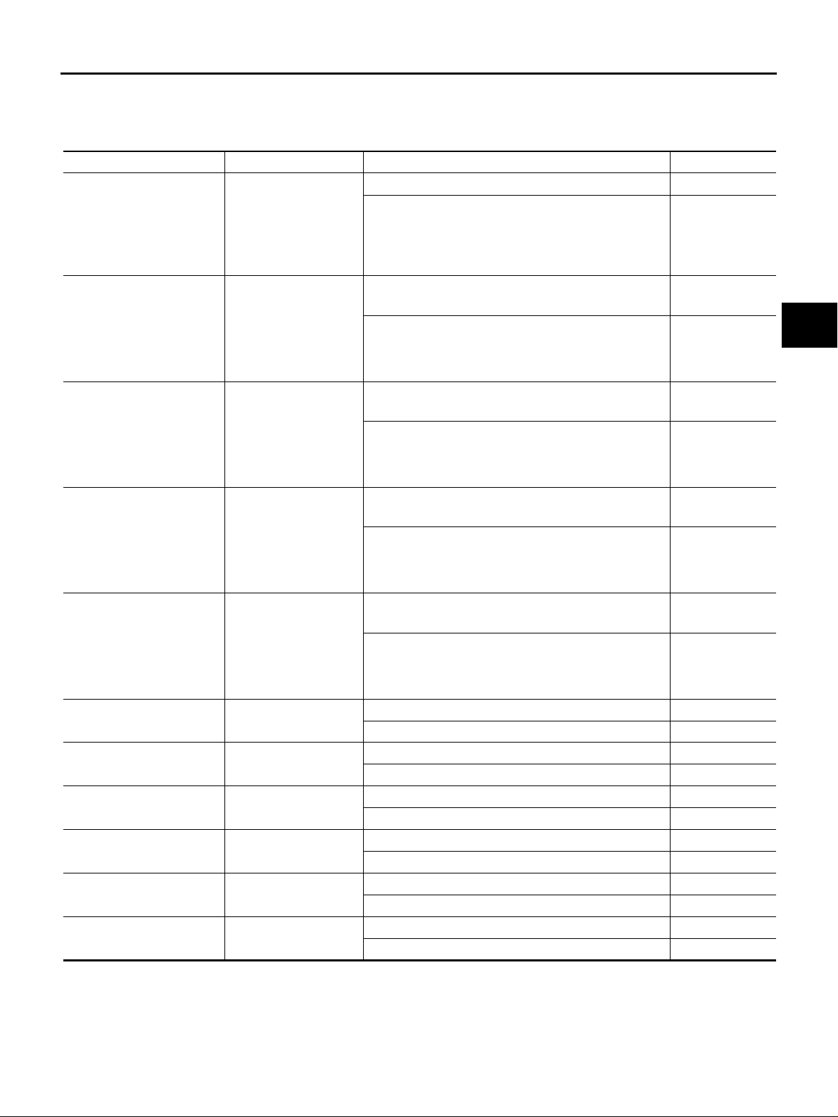
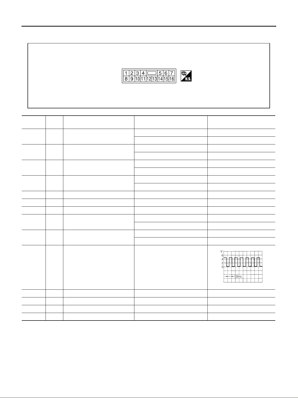
Low Tire Pressure Warning Control Unit Input/Out-
put Signal Reference Values .................................. 17
LOW TIRE PRESSURE WARNING CONTROL
UNIT INSPECTION TABLE ................................. 17
CONSUL T-II Function (AIR PRESSURE MONI-
TOR) ...................................................................... 19
ROAD WHEELS & TIRES
FUNCTION .................................. ........................19
CONSULT-II SETTING PROCEDURE ................19
WORK SUPPORT MODE ................................... 19
SELF-DIAG RESULT MODE ............................... 19
DATA MONITOR MODE ......................................21
LOW TIRE PRESSURE WARNING CONTROL
UNIT PART NUMBER MODE ............................. 21
Self-Diagnostic Procedure ......................................21
SELF-DIAGNOSTIC PROCEDURE (WITH
CONSULT-II) ....................................................... 21
SELF-DIAGNOSTIC PROCEDURE (WITHOUT
CONSULT-II) ....................................................... 21
ERASE SELF-DIAGNOSIS ...................... ....... ....23
ID Registration Procedure ........ ...... ....... ...... ....... .... 24
ID REGISTRATION WITH TRANSMITTER
ACTIVATION TOOL ............................................24
ID REGISTRATION WITHOUT T RANSMITTER
ACTIVATION TOOL ............................................24
Transmitter Wake Up Operation ............................. 25
WITH ACTIVATION TOOL .................................. 25
Inspections Before Trouble Diagnosis ....................26
DIAGNOSTIC PROCEDURE ..............................26
Trouble Diagnosis Chart for Symptoms .................. 26
Low Tire Pressure Warning Lamp Symptom Chart ...27
TROUBLE DIAGNOSIS FOR SYSTEM ... ...... ....... .... 29
Power Supply Circuit ..............................................29
LOW TIRE PRESSURE WARNING CONTROL
UNIT TERMINALS AND REFERENCE VALUE ...29
DIAGNOSTIC PROCEDURE ..............................29
Transmitter (NO DATA) ........................................... 31
CONSUL T-II REFERENCE VALUE IN DATA
MONITOR MODE ................................................ 31
DIAGNOSTIC PROCEDURE ..............................31
Transmitter (CHECKSUM ERR, CODE ERR, BATT
VOLT LOW) ............................................................33
CONSUL T-II REFERENCE VALUE IN DATA
MONITOR MODE ................................................ 33
DIAGNOSTIC PROCEDURE ..............................33
Transmitter (PRESSDATA ERR) ............................ 35
CONSUL T-II REFERENCE VALUE IN DATA
C
D
WT
F
G
H
I
J
K
L
M
Revision: 2005 November 2006 Q45
WT-1
Page 2

MONITOR MODE ................................................35
DIAGNOSTIC PROCEDURE ... ....... ...... ....... ....... 35
Vehicle Speed Signal ..............................................36
CONSULT-II REFERENCE VALUE IN DATA
MONITOR MODE ................................................36
LOW TIRE PRESSURE WARNING CONTROL
UNIT TERMINALS AND REFERENCE VALUE ...36
DIAGNOSTIC PROCEDURE ... ....... ...... ....... ....... 37
Component Inspection ............................................39
COMBINATION FLASHER UNIT ........................39
TROUBLE DIAGNOSIS FOR SYMPTOMS ..............40
Low Tire Pressure Warning Lamp Does Not Turn
ON for Approx.1 Second When Ignition Switch Is
Turned ON ..............................................................40
DIAGNOSTIC PROCEDURE ... ....... ...... ....... ....... 40
Low Tire Pressure Warning Lamp Stays ON When
Ignition Switch Is Turned ON ..................................42
DIAGNOSTIC PROCEDURE ... ....... ...... ....... ....... 42
Low Tire Pressure Warning Lamp Blinks When Igni-
tion Switch Is Turned ON ........................................44
SYMPTOM: ...................................... ...... ....... ....... 44
DIAGNOSTIC PROCEDURE ... ....... ...... ....... ....... 44
Hazard Warning Lamp Blinks When Ignition Switch
Is Turned ON ..........................................................45
DIAGNOSTIC PROCEDURE ... ....... ...... ....... ....... 45
“TIRE PRESSURE” Information In Display Does
Not Exist .................................................................46
DIAGNOSTIC PROCEDURE ...............................46
ID Registration Cannot Be Completed ....................48
DIAGNOSTIC PROCEDURE ...............................48
CONTROL UNIT ................... ....... ...... ....... ...... ....... ....49
Removal and Installation .........................................49
REMOVAL ........................................................ ....49
INSTALLATION ................................................ ....49
COMBINATION FLASHER UNIT ..............................50
Removal and Installation .........................................50
REMOVAL ........................................................ ....50
INSTALLATION ................................................ ....50
TRANSMITTER .........................................................51
Removal and Installation .........................................51
REMOVAL ........................................................ ....51
INSTALLATION ................................................ ....51
ROAD WHEEL ..........................................................53
Inspection ..................... ............. ............. ............. ....53
ALUMINUM WHEEL ............................................53
STEEL WHEEL (FOR EMERGENCY USE) ........53
ROAD WHEEL TIRE ASSEMBLY .............................54
Balancing Wheels (Bonding Weight Type) ..............54
REMOVAL ........................................................ ....54
WHEEL BALANCE ADJUSTMEN T .......... ....... ....54
Tire Rotation ............................................................55
SERVICE DATA AND SPECIFICATIONS (SDS) ......56
Road Wheel ....................... ....... ...... ........................56
Tire ......................................................... .................56
Tightening Torque ...................................................56
Revision: 2005 November 2006 Q45
WT-2
Page 3
PRECAUTIONS
PRECAUTIONS PFP:00001
Precautions for Supplemental Restraint System (SRS) “AIR BAG” and “SEAT BELT PRE-TENSIONER”
NES000CS
A
The Supplemental Rest raint System such as “AIR BAG” and “SEAT BELT PRE-TENSIONER”, used al ong
with a front seat belt, helps to redu ce th e risk or se verit y of i njury to the driv er and front passenge r for ce rtain
types of collision. This system includes seat belt switch inputs and dual st age front air bag modules. The SRS
system uses the seat belt switches to determine the front air bag deployment, and may only deploy one front
air bag, depending on the severity of a collision and whether the front occupants are belted or unbelted.
Information necessary to service the system safely is included in the SRS and SB section of this Service Manual.
WARNING:
● To avoid rendering the SRS inopera tive, whi ch could incr ease the risk of pe rsonal injury or death
in the event of a collision which would result in air bag inflation, all maintenance must be performed by an authorized NISSAN/INFINITI dealer.
● Improper maintenance, inc luding incorrect removal and installation of the SRS, can lead to per-
sonal injury ca use d by unintentional ac tiv atio n o f the s ys tem . F or re moval of Spiral C ab le and Air
Bag Module, see the SRS sec tion.
● Do not use electrical test equ ipment o n any circu it related to the SRS unless in structed to in this
Service Manual. SRS wiring harnesses can be identified by yellow and/ or orange harnesses or
harness connectors.
Precautions NES000CU
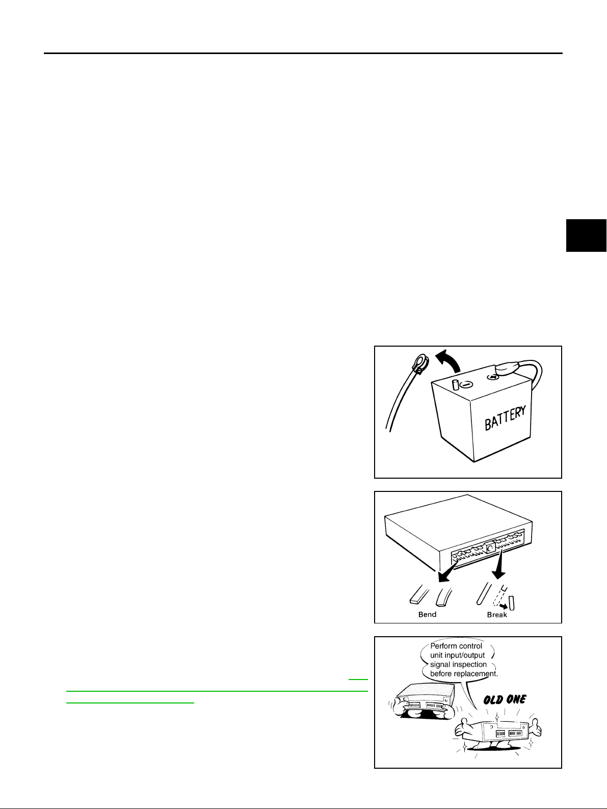
● Before connecting or disconnecting the low tire pressure
warning control unit harness connector, turn ignition
switch “OFF” and disconnect the battery cable from the
negative terminal. Battery voltage is applied to low tire
pressure warning control unit even if ignition switch is
turned “OFF”.
B
C
D
WT
F
G
H
I
● When connecting or disconnecting pin connectors i nto or
from low tire pressure warning control unit, take care not to
damage pin terminals (bend or brea k).
When connecting pin connectors make sure that there are
not any bends or breaks on low tire pressure warning control unit pin terminals.
● Before replacing low tire pressure warning control unit, per-
form low tire pressure warning control unit input/output
signal inspection and make sure whether low tire pressure
warning control unit func tion s p rope rl y or not. Refe r to WT-
17, "Low Tire Pressure Warning Control Unit Input/Output
Signal Reference Values" .
SEF289H
SEF291H
J
K
L
M
SDIA1848E
Revision: 2005 November 2006 Q45
WT-3
Page 4

PRECAUTIONS
Service Notice NES000CV
● ID registration is required when replacing or rotating wheels, replacing transmitter or low tire pressure
warning control unit. Refer to WT-24, "
ID Registration Procedure" .
Revision: 2005 November 2006 Q45
WT-4
Page 5
PREPARATION
PREPARATION PFP:00002
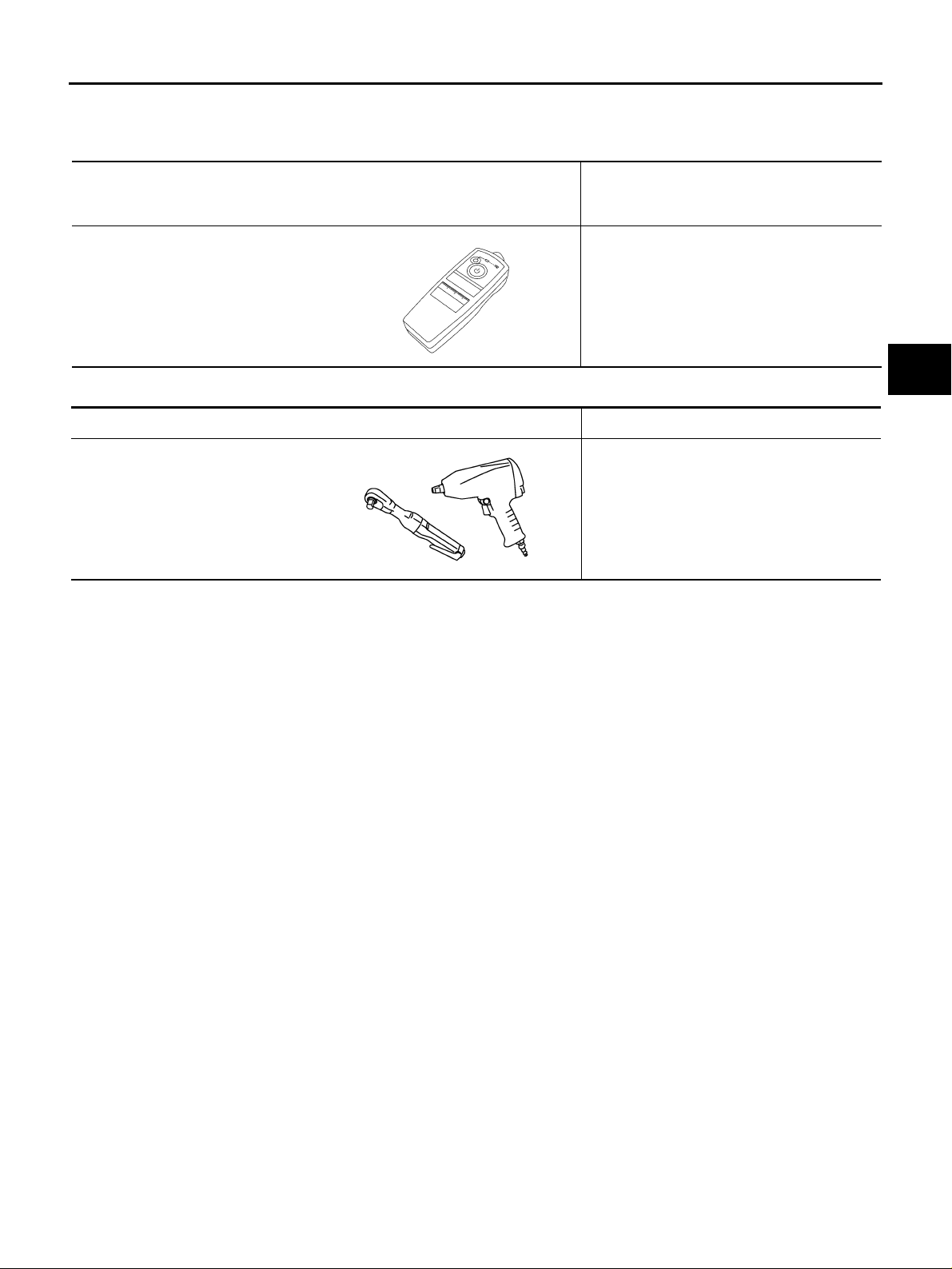
Special Service Tools NES000CW
The actual shapes of Kent-Moore tools may differ from those of spec ial ser vi ce tool s illust rat ed here.
Tool number
(Kent-Moore No.)
Tool name
Description
A
B
—
(J-45295)
Transmitter activation tool
SEIA0462E
ID registration
Commercial Service Tools NES000CX
Tool name Description
Power tool Removing wheel nuts
PBIC0190E
C
D
WT
F
G
H
I
J
K
M
L
Revision: 2005 November 2006 Q45
WT-5
Page 6
NOISE, VIBRATION AND HARSHNESS (NVH) TROUBLESHOOTING
NOISE, VIBRATION AND HARSHNESS (NVH) TROUBLESHOOTING PFP:00003 NVH Troubleshooting Chart NES00070
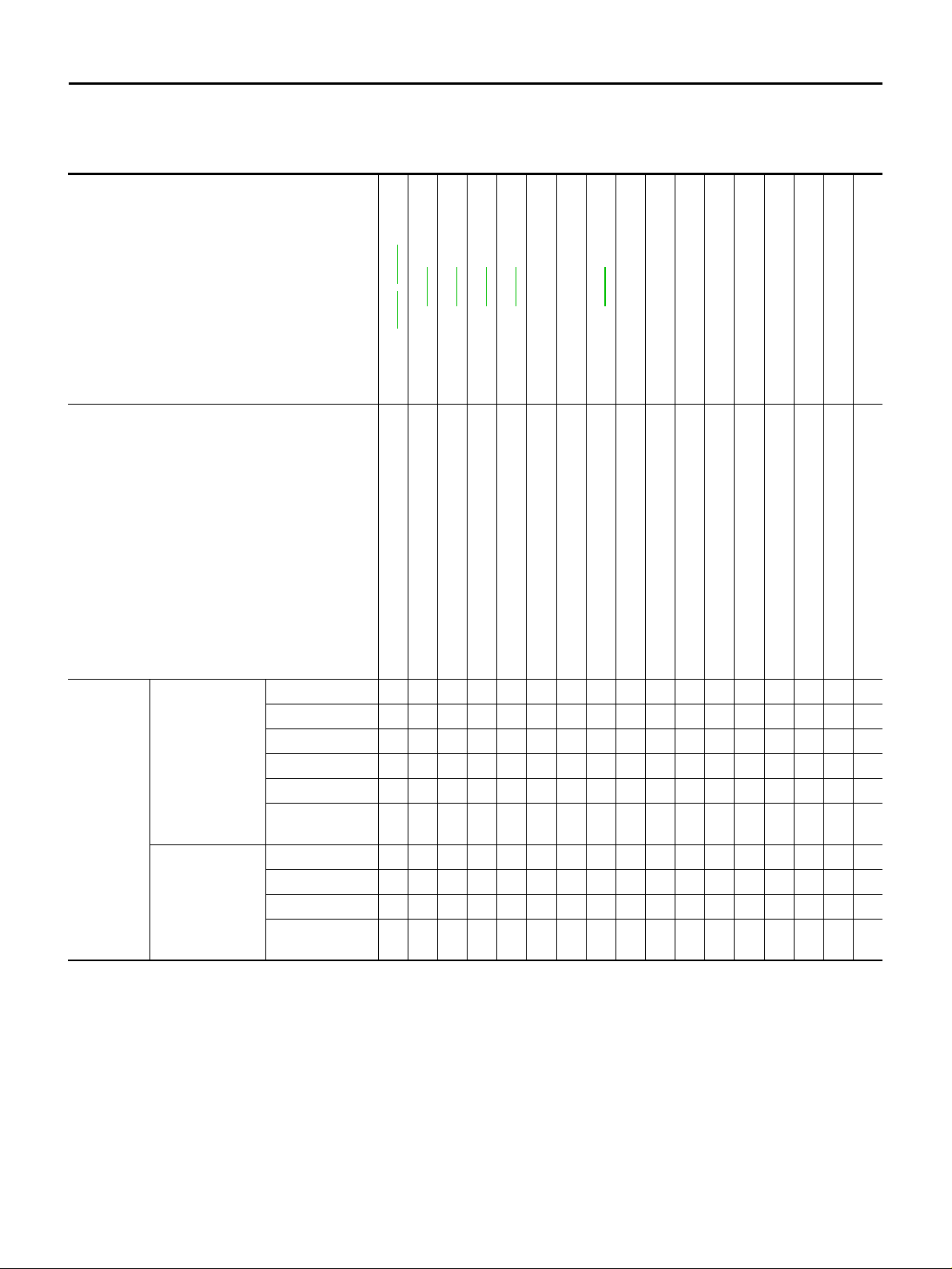
Use the chart below to help you fi nd the cause of the symptom. If necessary, repair or replace these parts .
Reference page
Possible cause and SUSPECTED PARTS
Noise Ч ЧЧЧЧЧЧ ×××× ××××
Shake Ч ЧЧЧЧЧ ×× ×× ××××
Vibration ×××××××
TIRES
Symptom
ROAD WHEEL
×: Applicable
Shimmy Ч ЧЧЧЧЧЧЧ ×× × ××
Judder Ч ЧЧЧЧЧ × ×× × ××
Poor quality ride
or handling
Noise × ×× × ЧЧЧЧЧ ×××
Shake × ×× × × ××× ×××
Shimmy, judder × ×× × ××× ××
Poor quality ride
or handling
—
—
WT-53
WT-54
WT-56
WT-55
FAX-4, FSU-7
Improper installation, looseness
Out-of-round
Imbalance
Incorrect tire pressure
Uneven tire wear
Deformation or damage
Ч ЧЧЧЧЧ × ×× ×
× ×× × ×××
WT-56
NVH in PR section
NVH in RFD section
NVH in FAX and FSU sections
NVH in RAX and RSU sections
Refer to TIRES in this chart
Refer to ROAD WHEEL in this chart
Non-uniformity
Incorrect tire size
PROPELLER SHAFT
DIFFERENTIAL
FRONT AXLE AND FRONT SUSPENSION
REAR AXLE AND REAR SUSPENSION
TIRES
ROAD WHEEL
NVH in RAX section
NVH in BR section
DRIVE SHAFT
BRAKE
NVH in PS section
STEERING
Revision: 2005 November 2006 Q45
WT-6
Page 7
LOW TIRE PRESSURE WARNING SYSTEM
LOW TIRE PRESSURE WARNING SYSTEM PFP:40300
System Description NES00075
DESCRIPTION
During driving, the low tire pressure warning system receives the signal transmitted from the transmitter
installed in each w he el , an d g iv es al arm s w he n th e t ire pressure becom es lo w. The control unit of this system
has pressure judgement and trouble diagnosis functions.
A
B
FUNCTION
When the low tir e pressure warning system detects low inflation pressure or another unusu al symptom, the
warning lamps on the instrument panel comes on. To start the self-diagnostic results mode, ground the selfdiagnostic (check) terminal. The malfunction location is indicated by the warning lamp flashing and the buzzer
sounds.
TRANSMITTER
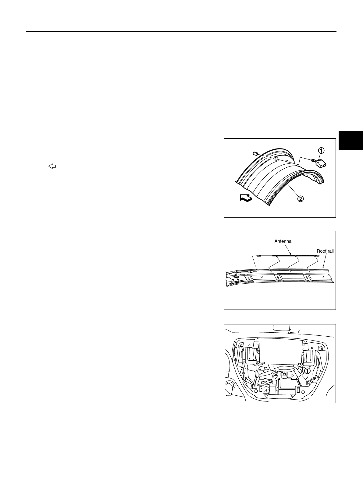
A sensor-transmitter (1) integrated with a valve is installed on a
wheel (2), and transmits a dete ct ed air pre ss ure si gn al in the form of
a radio wave.
Outer
:
SEIA0768E
ANTENNA
Receives the radio wav e si gn al transmitted by the transm itter.
C
D
WT
F
G
H
I
J
LOW TIRE PRESSURE WARNING CONTROL UNIT
Reads the radio wave signal re ceived by the antenna, and c ontrols
the low tire pressure warning lamp and the buzzer operations. It also
has a judgement function to detect a system malfunction.
1: Low tire pressure warning control unit
SEIA0042E
SEIA0739E
K
L
M
Revision: 2005 November 2006 Q45
WT-7
Page 8
LOW TIRE PRESSURE WARNING SYSTEM
LOW TIRE PRESSURE WARNING LAMP AND BUZZER
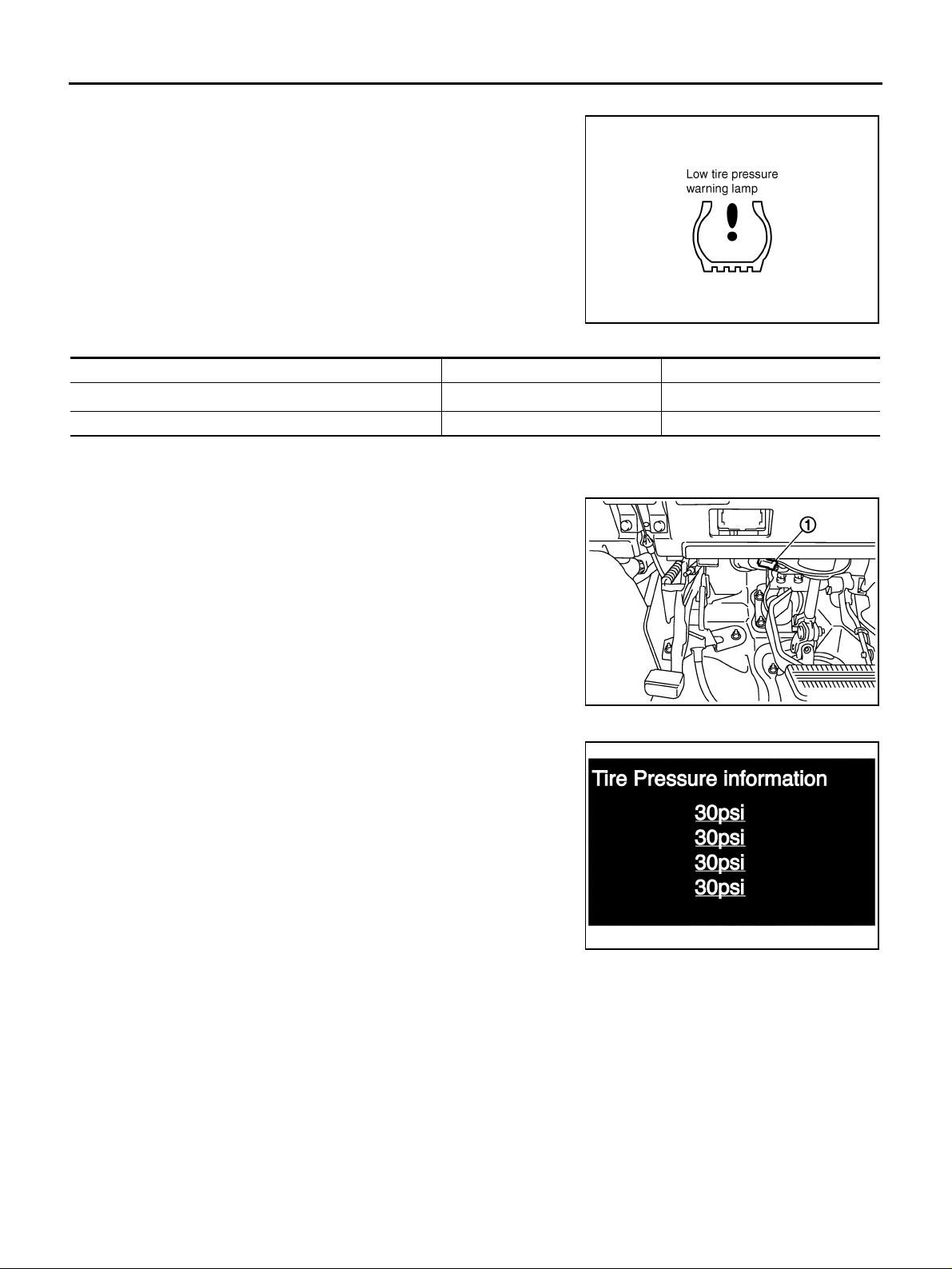
● Turns ON when there is a malfunction in low tire pressure warn-
ing system.
● Turns ON when ignition switch is turned ON, for purpose of lamp
check. Turns OFF approximately for 1 second after the engine
starts if system is no rmal.
Low Tire Pressure Warning Lamp
Condition Warning lamp Buzzer
2
Less than 186 kPa (1.86 kg/cm
System malfunction ON OFF
*: Standard air pressure is for 230 kPa (2.3 kg/cm2 , 33 psi) vehicle.
, 27 psi)*
TIRE PRESSURE WARNING CHECK SWITCH
The following item can be checked by grounding the tire pressure
warning check switch (1) harness connector terminal.
● The low tire pressure warning lamp in the combination meter will
flicker according to the self-diagnostic results.
ON Sounds for 10 sec.
SEIA0434E
VEHICLE INFORMATION DISPLAY
Displays the air pressure of each tire.
● After the ignition switc h is turned ON, the pressure valu es are
not be displayed until the data of all four wheels stabilizes.
SEIA0740E
SEIA0044E
Revision: 2005 November 2006 Q45
WT-8
Page 9
LOW TIRE PRESSURE WARNING SYSTEM
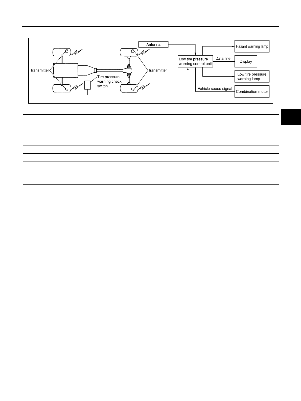
System Diagram NES000CY
A
B
C
SEIA0741E
COMPONENTS FUNCTION DESCRIPTION
Component parts Function
Low tire pressure warning control uni t Monitors tire pressure and controls the low tire pressure warning lamp and turn signal lamp.
Transmitter Converts tire pressure signals to radio signals .
Antenna Receives radio signals converted from tir e pres sure signals.
Display Displays the air pressure of each tire.
Tire pressure warning check switch Allows a mode to be switched to a diagnosis mode.
Hazard warning lamp ID registration of each wheel has been complet ed, turn si gnal lamp flashes two times.
Combination meter Transmitters the vehicle speed signal to low tire pressure warn ing cont rol unit.
Low tire pressure warning lamp Illuminates if malfunction is detected in electrical system of low tire pressure warning system.
D
WT
F
G
H
I
J
K
Revision: 2005 November 2006 Q45
WT-9
L
M
Page 10
TROUBLE DIAGNOSIS
TROUBLE DIAGNOSIS PFP:00004 How to Perform Trouble Diagnosis NES000CZ
BASIC CONCEPT
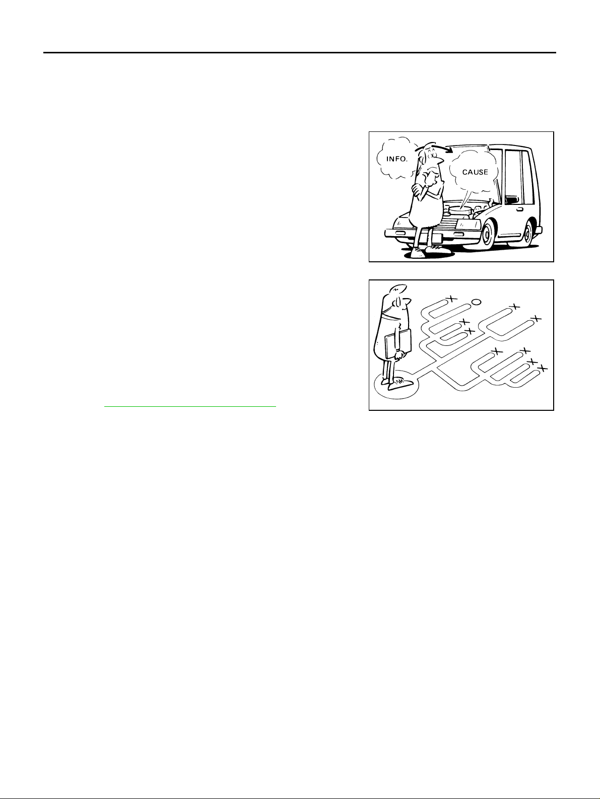
● To perform trouble diagnosis, it is th e most im portant to ha ve unde rstanding abou t vehic le systems (con-
trol and mechanism) thoroughly.
● It is also important to clarify cus tome r comp laints be fore in spec -
tion.
First of all, reproduce symptoms, and understand them fully.
Ask customer about his/her complaint s carefully. I n some cases,
it will be necessary to check symptoms by driving vehicle with
customer.
CAUTION:
Customers are not profes sional. It is dangerous to m ak e an
easy guess like “maybe the customer means that...,” or
“maybe the customer mentions this symptom”.
SEF233G
● It is essential to check symptoms right from the beginning in
order to repair malfunctions completely.
For intermittent malfunctions, reproduce symptoms based on
interview with customer and past examples. Do not perform
inspection on ad hoc basis. Most intermittent malfunctions are
caused by poor contacts. In this case, it will be effective to shake
suspected harness or connector by ha nd. When repairing wit hout any symptom diagnosis, you cannot judge if malfunctions
have actually been eliminated.
● After completing diagnosis, always erase diagnostic memory.
Refer to WT-23, "
● For intermittent malfunctions, move harness or harness connec-
tor by hand. Then check for poor contact or reproduced open circuit.
ERASE SELF-DIAGNOSIS" .
SEF234G
INTRODUCTION
● Before troubleshooting, verify customer complaints.
● If a vehicle malfunction is difficult to reproduce, harnesses, harness connectors or terminals may be mal-
functioning. Hold and shake these parts to make sure they are securely connected.
● When using a circuit tester to measure voltage or resistance of each circuit, be careful not to damage or
deform connector terminals.
Revision: 2005 November 2006 Q45
WT-10
Page 11
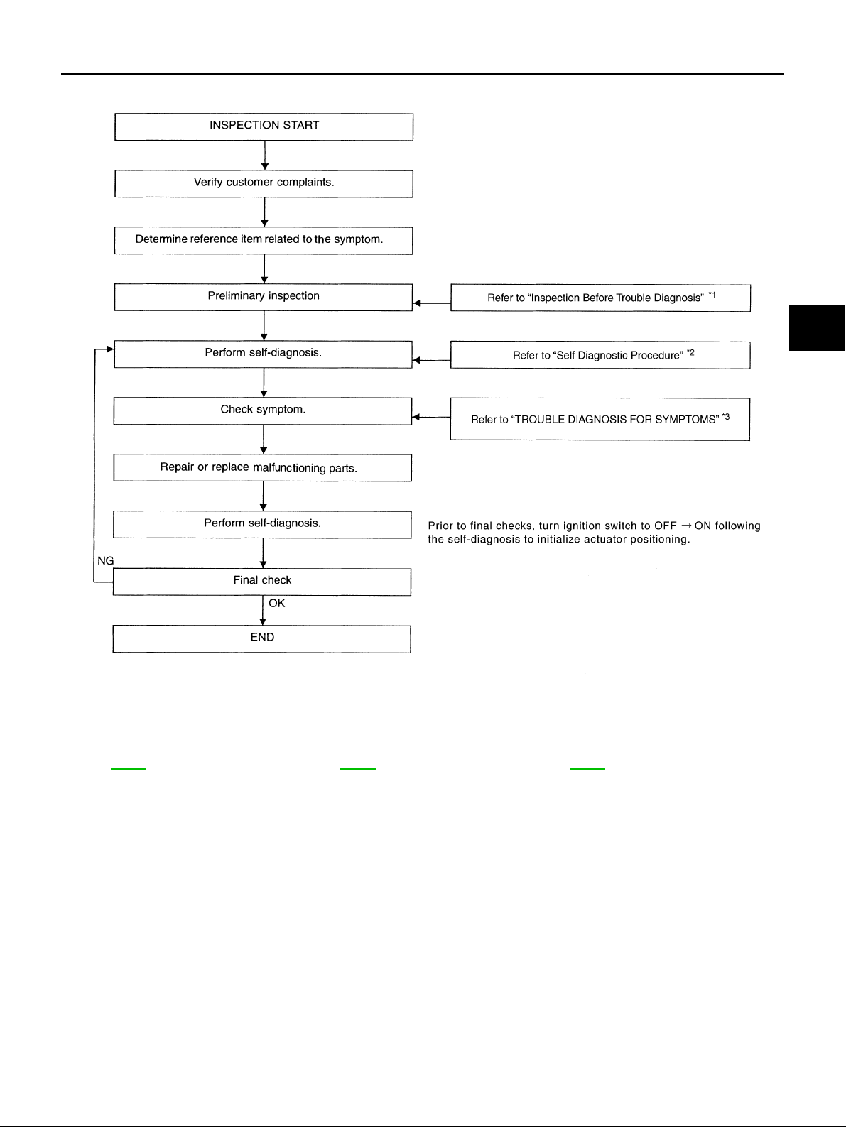
WORK FLOW
TROUBLE DIAGNOSIS
A
B
C
D
WT
F
G
*1: WT-26 *2: WT-21 *3: WT-40
H
I
J
K
L
SEIA0770E
M
Revision: 2005 November 2006 Q45
WT-11
Page 12
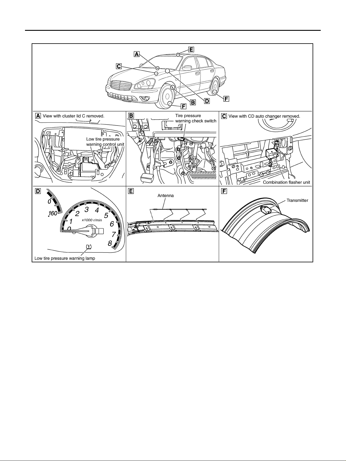
TROUBLE DIAGNOSIS
Component Parts Location NES000D1
SEIA0783E
Revision: 2005 November 2006 Q45
WT-12
Page 13
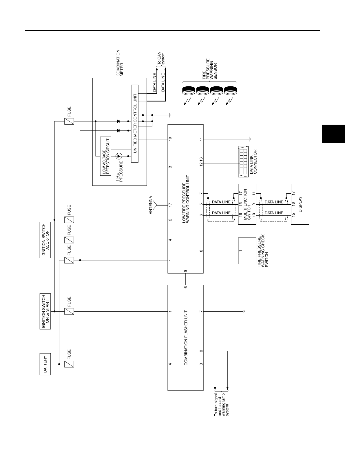
TROUBLE DIAGNOSIS
Circuit Diagram NES000D2
A
B
C
D
WT
F
G
H
K
M
I
J
L
TEWM0092E
Revision: 2005 November 2006 Q45
WT-13
Page 14
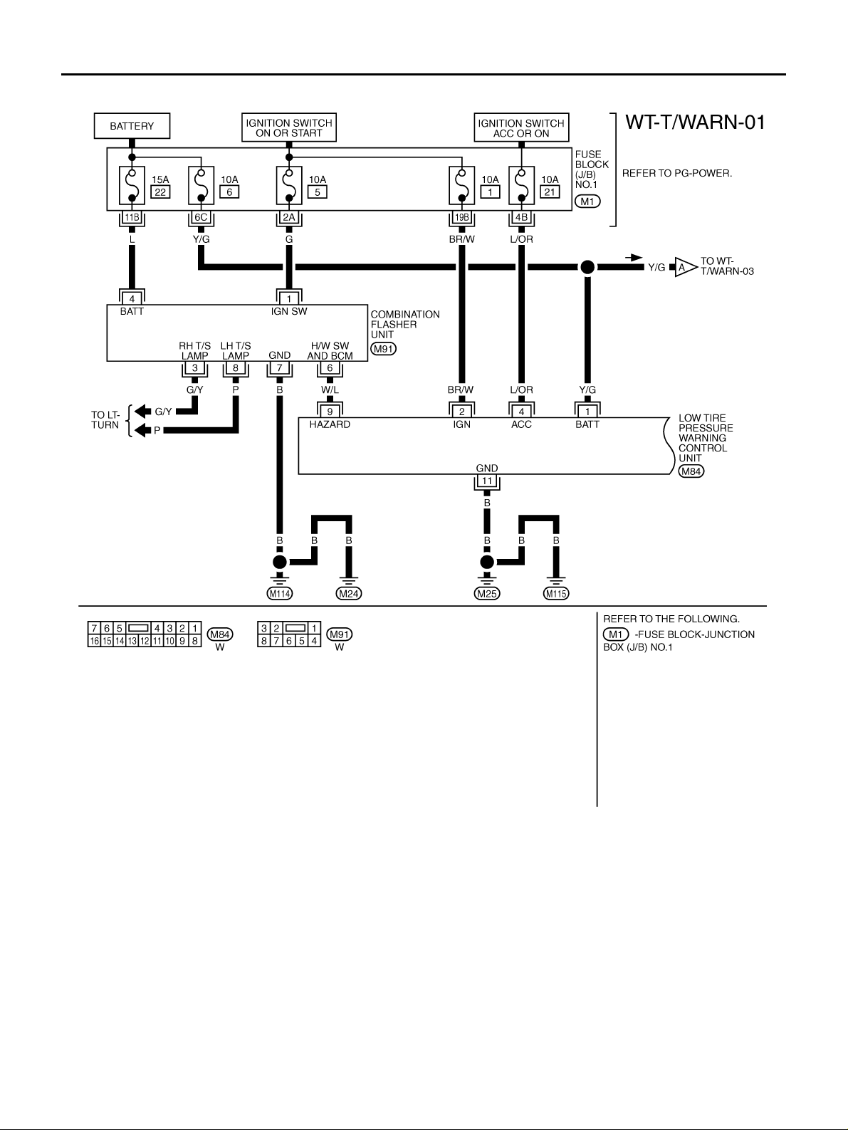
TROUBLE DIAGNOSIS
Wiring Diagram — T/WARN — NES00076
TEWM0080E
Revision: 2005 November 2006 Q45
WT-14
Page 15
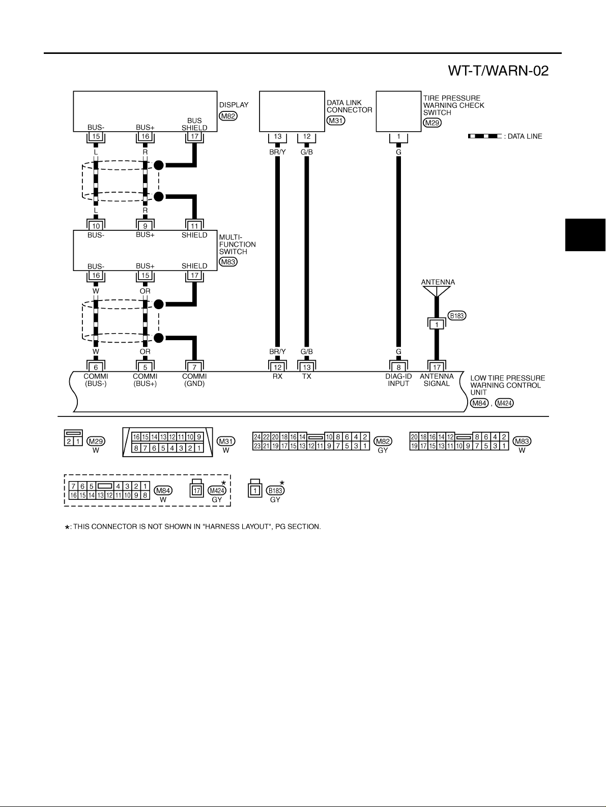
TROUBLE DIAGNOSIS
A
B
C
D
WT
F
G
TEWM0125E
H
I
J
K
L
M
Revision: 2005 November 2006 Q45
WT-15
Page 16
TROUBLE DIAGNOSIS
TEWM0082E
Revision: 2005 November 2006 Q45
WT-16
Page 17
TROUBLE DIAGNOSIS
Low Tire Pressure Warning Control Unit Input/Output Signal Reference Values
NES000D4
LOW TIRE PRESSURE WARNING CONTROL UNIT INSPECTION TABLE
Specifications with CONSULT-II
Monitor item [Unit] Content Condition Display value
Vehicle stopped 0 km/h (0 MPH)
VHCL SPEED SE [km/h] or
[mph]
AIR PRESS FL [kPa], [kg/
2
] or [psi]
cm
AIR PRESS FR [kPa], [kg/
2
] or [psi]
cm
AIR PRESS RR [kPa], [kg/
2
] or [psi]
cm
AIR PRESS RL [kPa], [kg/
2
] or [psi]
cm
ID REGST FL [DONE/YET]
ID REGST FR [DONE /YET]
ID REGST RR [DONE/YET]
ID REGST RL [DONE/YET]
WARNING LAMP [ON/OFF]
BUZZER [ON/OFF] Condition of sound
Wheel speed
Condition of front LH
tire air pressure
Condition of front RH
tire air pressure
Condition of rear RH
tire air pressure
Condition of rear LH tire
air pressure
Condition of front LH ID
registration
Condition of front RH ID
registration
Condition of rear RH ID
registration
Condition of rear LH ID
registration
Low tire pressure warning lamp condition
Vehicle running
CAUTION:
Check air pressure of tire under standard condition.
Just after the engine is started
Start engine and drive at 40 km/h (25 MPH) or more for
several minutes.
Just after the engine is started
Start engine and drive at 40 km/h (25 MPH) or more for
several minutes.
Just after the engine is started
Start engine and drive at 40 km/h (25 MPH) or more for
several minutes.
Just after the engine is started
Start engine and drive at 40 km/h (25 MPH) or more for
several minutes.
Transmitter ID registered DONE
Transmitter ID unregist ered YET
Transmitter ID registered DONE
Transmitter ID unregist ered YET
Transmitter ID registered DONE
Transmitter ID unregist ered YET
Transmitter ID registered DONE
Transmitter ID unregist ered YET
Low tire pressure warning lamp: ON ON
Low tire pressure warning lamp: OFF OFF
Sound heard ON
Sound not heard OFF
Approximately
equal to the indication on speedometer (Inside of
±10%)
0 kPa (0 kg/cm
0 psi)
Approximately
equal to the indication on tire
gauge value
0 kPa (0 kg/cm
0 psi)
Approximately
equal to the indication on tire
gauge value
0 kPa (0 kg/cm
0 psi)
Approximately
equal to the indication on tire
gauge value
0 kPa (0 kg/cm
0 psi)
Approximately
equal to the indication on tire
gauge value
A
B
C
D
2
,
WT
F
2
,
G
H
2
,
I
2
,
J
K
L
M
Revision: 2005 November 2006 Q45
WT-17
Page 18
TROUBLE DIAGNOSIS
Specifications Between Low Tire Pressure Warning Control Unit Terminals
LOW TIRE PRESSURE WARNING CONTROL UNIT CONNECTOR LAYOUT
Data are reference value and are measured between each terminal and ground.
Terminal
1Y/G
2 BR/W Power supply
3 LG Low tire pressure warning lamp
4 L/OR Power supply (ACC)
5 OR Display data line (+) Ignition switch: ON 0 - 5 V (alternately repeated)
6 W Display data line (-) Ignition switch: ON 0 - 5 V (alternately repeated)
7 — Display ground — —
8 G Tire pressure warning check switch
9 W/L Hazard warning lamp switch
Wire
color
Item Condition Data (Approx.)
Power supply
(Memory back-up)
Ignition switch: ON Battery voltage
Ignition switch: OFF Battery voltage
Ignition switch: ON Battery voltage
Ignition switch: OFF 0 V
Low tire pressure warning lamp: ON 5 - 8 V
Low tire pr e ssu re wa r ni n g l a mp : OF F 0 V
Ignition switch: ACC Battery voltage
Ignition switch: OFF 0 V
Ignition switch: ON 5 V
Ignition switch: OFF 5 V
Ignition switch: ON Battery voltage
Ignition switch: OFF Battery voltage
SEIA0743E
10 OR/L Vehicle speed Vehicle speed: 40 km/h (25 MPH)
ELF1080D
11 B Ground Always 0 V
12 BR/Y Data link connector (RX) — —
13 G/B Da ta link connector ( TX) — —
17 — Antenna — —
CAUTION:
When using circuit tester or oscilloscope to me asure vo ltage for inspection, be sur e not to ext end forcibly any connec tor terminals.
Revision: 2005 November 2006 Q45
WT-18
Page 19
TROUBLE DIAGNOSIS
CONSULT-II Function (AIR PRESSURE MONITOR) NES000D5
FUNCTION
CONSULT-II can display each diagnostic item using the diagnostic test modes shown following.
Diagnostic test mode Function
Work support
Self-diagnostic results ● Self-diagnostic results can be read and erased quickly. WT-19
Data monitor ● Input/Output data in the low tire pressure warning control u nit can be read . WT-21
ECU part number ● Low tire pressure warning control unit part number can be read. WT-21
● This mode enables a technician to adjust some devices faster and more accu-
rately by following the indications on CONSU LT-II.
CONSULT -II SETTING PROCEDURE
Refer to GI-36, "CONSULT-II Start Procedure" .
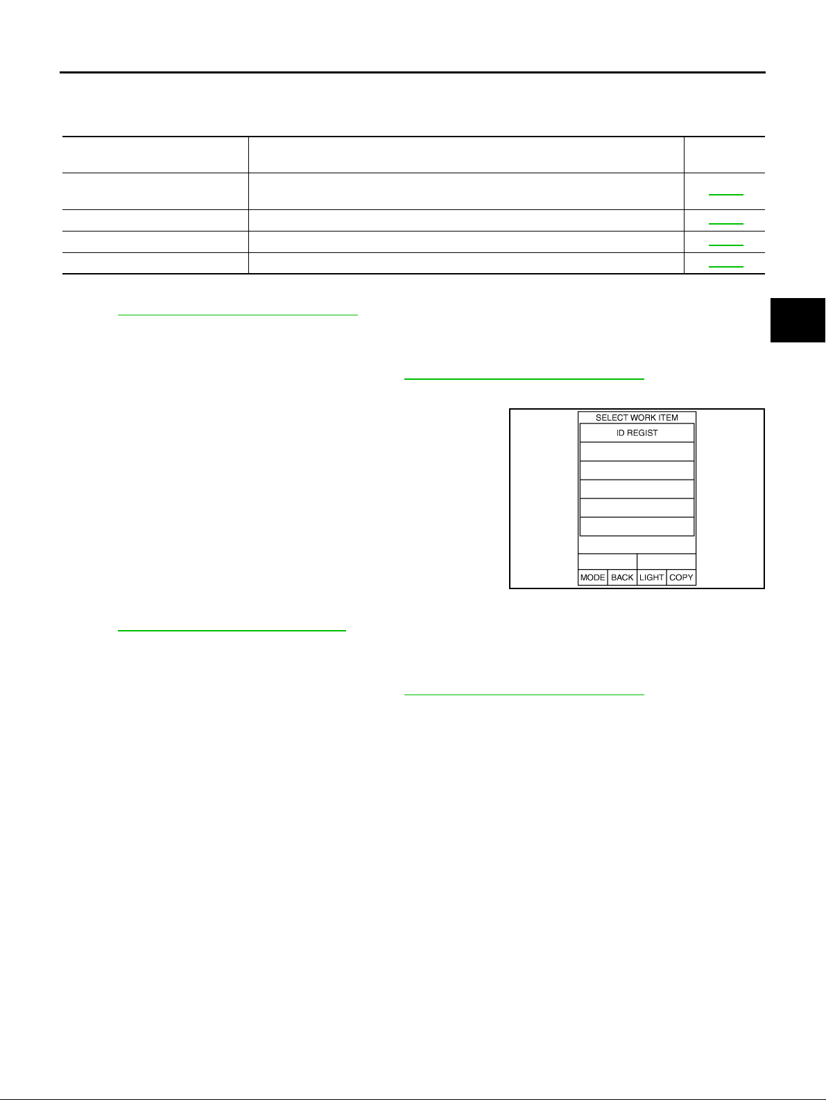
WORK SUPPORT MODE
Operation Procedure
1. Perform “CONSULT -II Start Procedure”. Refer to GI-36, "CONSULT-II Start Procedure" .
2. Touch “WORK SUPPORT”.
3. Select from “SELECT WORK ITEM”, screen of work support
mode is displayed.
Reference
page
WT-19
A
B
C
D
WT
F
G
ID Regist
Refer to WT-24, "ID Registration Procedure" .
SELF-DIAG RESULT MODE
Operation Procedure
1. Perform “CONSULT -II Start Procedure”. Refer to GI-36, "CONSULT-II Start Procedure" .
2. With engine at idle, touch “SELF-DIAG RES ULTS”.
Display shows malfunction experienced since the last erasing operation.
NOTE:
The details for “TIME” are as follows:
● “0”: Error currently detected with low tire pressure warn in g contro l unit.
● Except for “0”: Error detected in the past and memorized with low tire pressure warning control unit.
Detects frequency of driving after DTC occurs (frequency of turning ignition switch “ON/OFF”).
H
I
SEIA0772E
J
K
L
M
Revision: 2005 November 2006 Q45
WT-19
Page 20

TROUBLE DIAGNOSIS
Display Item List
Items
(CONSULT-II screen terms)
FLAT TIRE FL
FLAT TIRE FR
FLAT TIRE RR
FLAT TIRE RL
[NO DATA] FL Data from front LH transmitter cannot be received.
[NO DATA] FR Data from front RH transmitter cannot be received.
[NO DATA] RR Data from rear RH transmitter cannot be receive d.
[NO DATA] RL Data from rear LH transmitter cannot be received.
[CHECKSUM ERR] FL Checks um data from front LH trans mit te r is malfunct ioni ng.
[CHECKSUM ERR] FR Checksum data from front RH transmitter is malfunctioning.
[CHECKSUM ERR] RR Checksum data from rear RH transmitter is malfunctioning.
[CHECKSUM ERR] RL Checksum data from rear LH transmitter is malfunctioning.
[PRESSDATA ERR] FL Air pressure data from front LH transmitter is malfunction.
[PRESSDATA ERR] FR Air pressure data from front RH transmitter is malfunction.
[PRESSDATA ERR] RR Air pressure data from rear RH transmitter is malfunction.
[PRESSDATA ERR] RL Air pressure data from rear LH transmitter is malfunction.
[CODE ERR] FL Function code data from front LH transmitter is malfunctioni ng.
[CODE ERR] FR Function code data from front RH transmitter is malfunct ioni ng.
[CODE ERR] RR Function cod e data from rear RH trans mit te r is malfunct i oning.
[CODE ERR] RL Funct ion code data from rear LH transmitter is malfunctioning.
[BATT VOLT LOW] FL Battery voltage of front LH transmitter drops.
[BATT VOLT LOW] FR Battery voltage of front RH transmitter drops.
[BATT VOLT LOW] RR Battery voltage of rear RH transmitter drops.
[BATT VOLT LOW] RL Battery voltage of rear LH transmitter drops.
RECEIVER ID NO REG No ID registration has been made to the low tire pressure warning control unit.
NOTE:
Before performing the self-d iagnosis, be sure to regist er the ID, or else the ac tual malfunction locat ion may be different from that displayed on CONSULT-II.
Front LH tire pressure drops to 186 kPa (1.86 kg/cm
Front RH tire pressure drops to 186 kPa (1.86 kg/cm
Rear RH tire pressure drops to 186 kPa (1.86 kg/cm
Rear LH tire pressure drops to 186 kPa (1.86 kg/cm
Diagnostic item is detected when... Check item
2
, 27 psi) or less
2
, 27 psi) or less
2
, 27 psi) or less
2
, 27 psi) or less
WT-26, "
Before Trouble Diag-
WT- 31, "
WT- 33, "
(CHECKSUM ERR,
CODE ERR, BATT
WT- 35, "
(PRESSDATA ERR)"
WT- 33, "
(CHECKSUM ERR,
CODE ERR, BATT
WT- 33, "
(CHECKSUM ERR,
CODE ERR, BATT
WT-48, "
tion Cannot Be Com-
Inspections
nosis"
Transmitter
(NO DATA)"
Transmitter
VOLT LOW)"
Transmitter
Transmitter
VOLT LOW)"
Transmitter
VOLT LOW)"
ID Registra-
pleted"
How to Erase Self-diagnostic Results
1. Perform applicable inspection of malfunctioning item and then repair or replace.
2. Turn ignition switch “ON” and select “SELF-DIAG RESULTS” mode for “AIR PRESSURE MONITOR” with
CONSULT-II.
3. Touch “ERASE” on CONSULT-II screen to erase DTC memory.
CAUTION:
If memory cannot be erased, perform applicable diagnosis.
Revision: 2005 November 2006 Q45
WT-20
Page 21
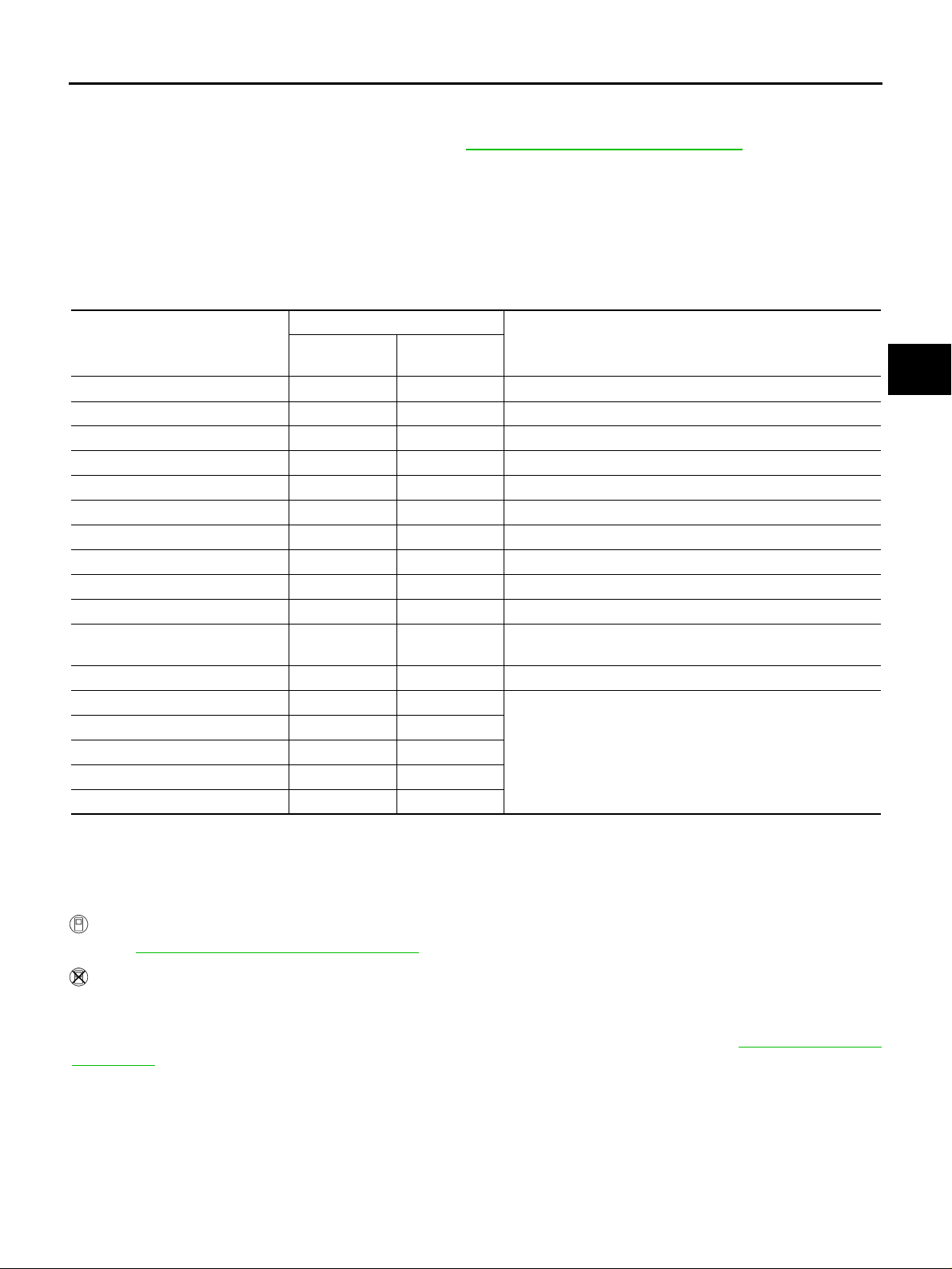
TROUBLE DIAGNOSIS
DATA MONITOR MODE
Operation Procedure
1. Perform “CONSULT -II Start Procedure”. Refer to GI-36, "CONSULT-II Start Procedure" .
2. Touch “DATA MONITOR”.
3. Select from “SELECT MONITOR ITEM”, screen of data monitor mo de is displayed.
NOTE:
When malfunction is detected, CONSULT-II performs REAL-TIME DIAGNOSIS.
Also, any malfunction detected while in this mode will be displayed in real time.
Display Item List
×: Standard –: Not applicable
Monitor item selection
Monitored item (Unit)
VHCL SPEED SE [km/h] or [mph] ××Vehicle speed is displayed.
AIR PRESS FL [kpa] or [psi] ××Senses the front LH tire pressure is displayed.
AIR PRESS FR [kPa] or [psi] ××Senses the front RH tire pressure is displayed.
AIR PRESS RR [kpa] or [psi] ××Senses the rear RH tire pressure is displayed.
AIR PRESS RL [kpa] or [psi] ××Senses the rear LH tire pressure is displayed.
ID REGST FL [DONE/YET] ××Registration status of front LH ID is displayed.
ID REGST FR [DONE/YET] ××Registration status of front RH ID is displayed.
ID REGST RR [DONE/YET] ××Registration status of rear RH ID is displayed.
ID REGST RL [DONE/YET] ××Reg istr ation status of rear LH ID is displa yed.
WARNING LAMP [ON/OFF] ××Control status of low tire pressure warning lamp is displayed.
BUZZER [ON/OFF] ××
Voltage [V] – × The value measured by the voltage probe is di splayed.
Frequency [Hz] – ×
DUTY-HI (high) [%] – ×
DUTY-LOW (low) [%] – ×
PLS WIDTH-HI [msec] – ×
PLS WIDTH-LOW [msec] – ×
MAIN
SIGNALS
SELECTION
FROM MENU
Control status of buzzer in low tire pressure warnin g lamp
control unit is displayed.
The value measured by the pulse probe is displayed.
Remarks
LOW TIRE PRESSURE WARNING CONTROL UNIT PART NUMBER MODE
Ignore the low tire pressure warning control unit part number displayed in the “ECU PART NUMBER”.
Refer to parts catalog to order the low tire pressure warning control unit.
Self-Diagnostic Procedure NES000D6
SELF-DIAGNOSTIC PROCEDURE (WITH CONSULT-II)
Refer to WT-19, "SELF-DIAG RESULT MODE" .
A
B
C
D
WT
F
G
H
I
J
K
L
M
SELF-DIAGNOSTIC PROCEDURE (WITHOUT CONSULT-II)
Description
The low tire pressure warning lamp in the combination meter will flicker according to the self-diagnostic
results. As for the details of the low tire pressure warning lamp fli cker ing patterns, ref er to WT-22, "
Procedure" .
Revision: 2005 November 2006 Q45
WT-21
Diagnostic
Page 22
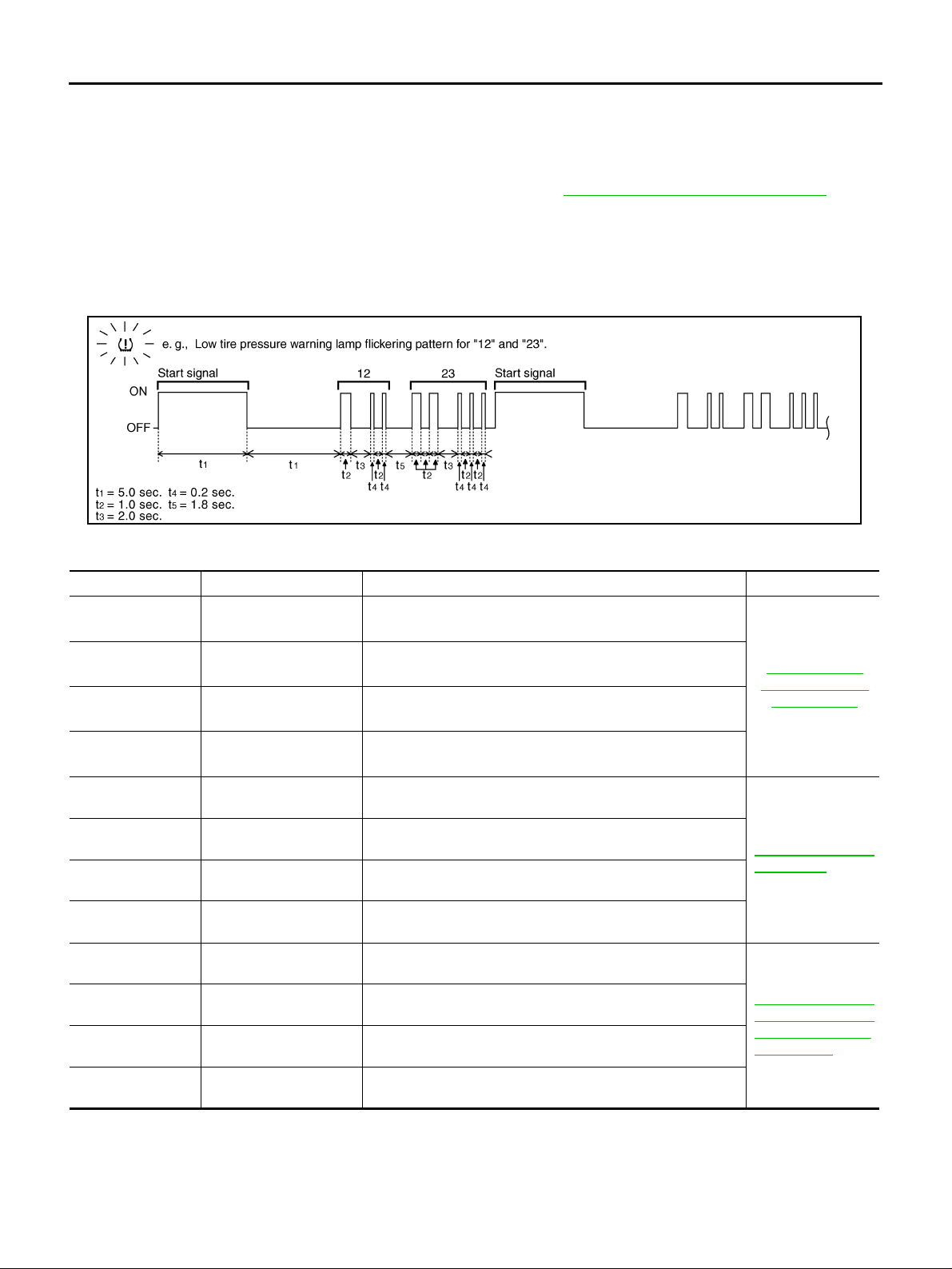
TROUBLE DIAGNOSIS
Diagnostic Procedure
1. Start the engi ne.
2. Perform the following procedures to enter the corresponding signals.
a. Ground the tire pressure warning check switch harness connector terminal 1 for more than 5 seconds.
b. Read the flickering of low tire pressure warning lamp. Refer to WT-22, "
NOTE:
When the low tire pressure warning lamp flashes 5 Hz and continues repeating it, the system is normal.
Judgement Self-diagnosis
When a malfunction is detected, the malfunction route is indicated by flickering of the low tire pressure warning lamp.
Judgement Self-diagnosis" .
SEIA0745E
NOTE:
When the low tire pressure warn ing lamp flashes 5 Hz and continues repeating it, the system is normal.
Flickering pattern Items Diagnostic item is detected when... Check item
15
16
17
18
21
22
23
24
31
32
33
34
Tire pressure value
(front LH)
Tire pressure value
(front RH)
Tire pressure value
(rear RH)
Tire pressure value
(rear LH)
Transmitter no data
(front LH)
Transmitter no data
(front RH)
Transmitter no data
(rear RH)
Transmitter no data
(rear LH)
Transmitter checksum
error (front LH)
Transmitter checksum
error (front RH)
Transmitter checksum
error (rear RH )
Transmitter checksum
error (rear L H )
Front LH tire pressure drops to 186 kPa (1.86 kg/cm
or less
Front RH tire pressure drops to 186 kPa (1.86 kg/cm
or less
Rear RH tire pressure drops to 186 kPa (1.86 kg/cm
or less
Rear LH tire pressure drops to 186 kPa (1.86 kg/cm
or less
Data from front LH transmitter cannot be received.
Data from front RH transmitter cannot be received.
Data from rear RH transmitter cannot be received.
Data from rear LH transmitter cannot be received.
Checksum data from front LH transmitter is malfun ct ion in g.
Checksum data from front RH transmitter is malfunctioning.
Checksum data from rear RH transmitter is mal fun ct ion in g.
Checksum data from rear LH transmitter is malfunct i oni ng.
2
, 27 psi)
2
, 27 psi)
2
, 27 psi)
2
, 27 psi)
WT-26, "
tions Before Trou-
WT- 31, "
(NO DATA)"
WT- 33, "
(CHECKSUM ERR,
CODE ERR, BATT
VOLT LOW)"
Inspec-
ble Diagn osis"
Transmitter
Transmitter
Revision: 2005 November 2006 Q45
WT-22
Page 23
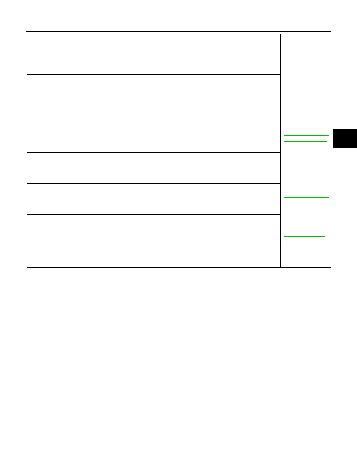
TROUBLE DIAGNOSIS
Flickering pattern Items Diagnostic item is detected when... Check item
35
36
37
38
41
42
43
44
45
46
47
48
51
No flickering
Transmitter pressure
data error (front LH)
Transmitter pressure
data error (front RH)
Transmitter pressure
data error (rear RH)
Transmitter pressure
data error (rear LH)
Transmitter function
code error (front LH)
Transmitter function
code error (front RH)
Transmitter function
code error (rear RH)
Transmitter function
code error (rear LH)
Transmitter battery voltage low (front LH)
Transmitter battery voltage low (front RH)
Transmitter battery voltage low (rear RH)
Transmitter battery voltage low (rear LH)
Low tire pressure warning control unit
Tire pressu re war ni ng
check switch
Air pressure data from front LH transmitter is malfunction.
Air pressure data from front RH transmitter is malfunction.
Air pressure data from rear RH transmitter is malfunction.
Air pressure data from rear LH transmitter is malfunction.
Function code data from front LH transmitter is malfunctioning.
Function code data from front RH transmitter is malfunctioning.
Function code data from rear RH transmitter is malfunctioning.
Function code data from rear LH transmitter is malfunctioning.
Battery voltage of front LH transmitter drops.
Battery voltage of front RH transmitter drops.
Battery voltage of rear RH transmitter drops.
Battery voltage of rear LH transmitter drops.
No ID registration has been made to the low tire pressure
warning control unit.
Tire pressure warning check switch circuit is open. —
WT-35, "
(PRESSDATA
ERR)"
WT-33, "
(CHECKSUM ERR,
CODE ERR, BATT
VOLT LOW)"
WT-33, "
(CHECKSUM ERR,
CODE ERR, BATT
VOLT LOW)"
WT-48, "
tration Cannot Be
Completed"
Transmitter
Transmitter
Transmitter
ID Regis-
A
B
C
D
WT
F
G
H
I
J
ERASE SELF-DIAGNOSIS
● In order to make it ea sier to find the cause of h ard-to-duplicate ma lfunctions, malfunct ion information is
stored into the control unit as necessary during use by the user. This memory is not erased no matter how
many times the ignition switch is turned “ON” and “OFF”.
● However, this information is erased by turning ignition switch “OFF” after performing self-diagnostics or by
erasing the me mory using the CONS ULT-II. Refer to WT-20, "
How to Erase Self-diagnostic Results" .
K
L
M
Revision: 2005 November 2006 Q45
WT-23
Page 24
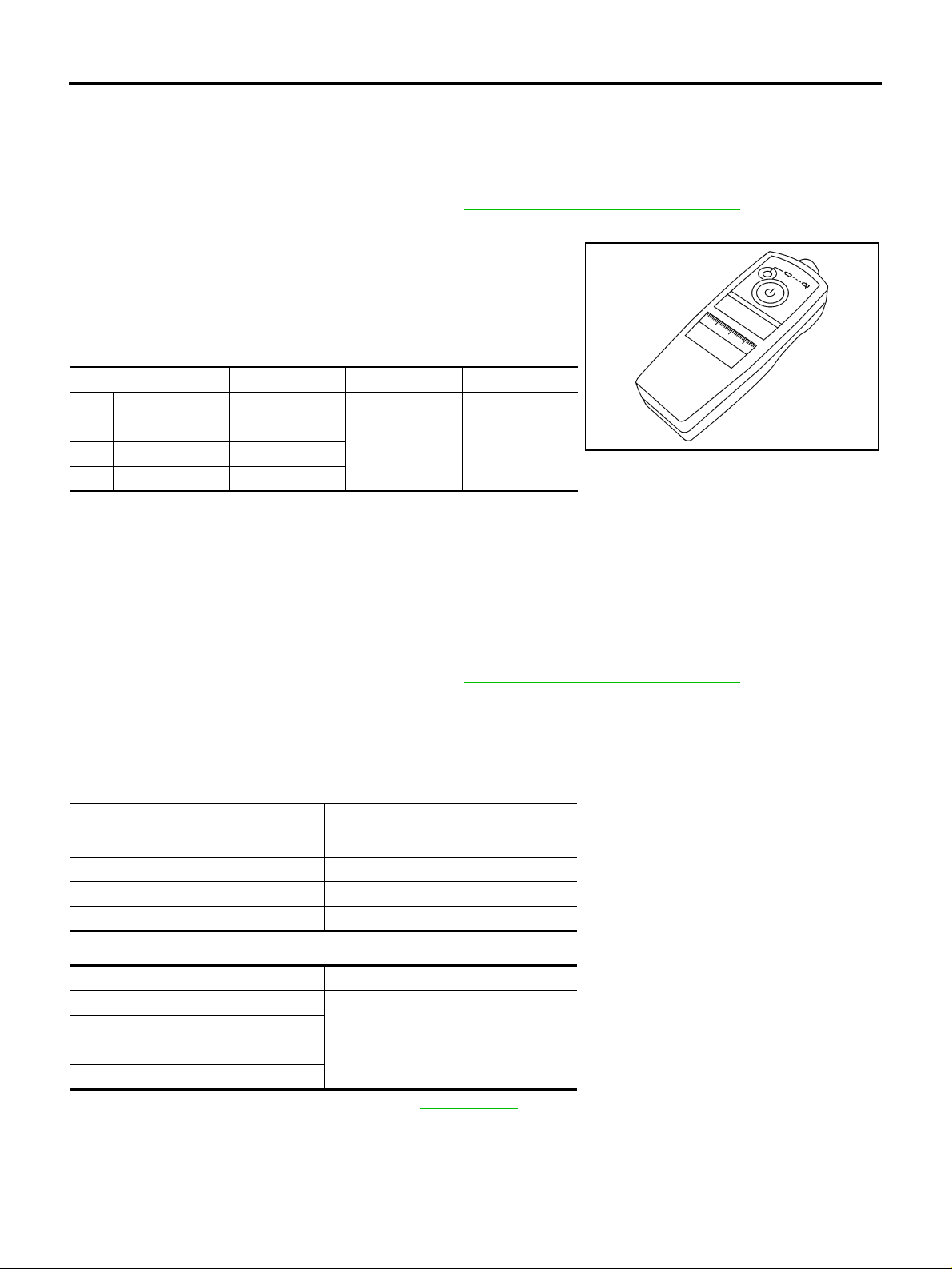
TROUBLE DIAGNOSIS
ID Registration Procedure NES000HE
ID REGISTRATION WITH TRANSMITTER ACTIVATION TOOL
CAUTION:
This procedure must be done after replacement of a transmitter, low tire pressure warning co ntrol
unit, or rotating wheels.
1. Perform “CONSULT-II Start Procedure”. Refer to GI-36, "
2. Touch “WORK SUPPORT” on “SELECT DIAG MODE” screen, and select “ID REGIST”.
3. With the transmitter activation tool (J-45295) pushed against the
front-left transmitter position of the air valve, press and hold the
button for 5 seconds.
4. Register the IDs in order from FR LH, FR RH, RR RH, to RR LH.
When ID registr ati o n of each w h eel ha s be en co mpl ete d, buzze r
sounds and turn signal lamp blinks.
Activation tire position Buzzer Turn signal lamp CONSU LT-II
1 Front LH Once
2 Front RH 2 times
3 Rear RH 3 times
4 Rear LH 4 times
2 times flashing
5. After completing all ID registrations, press “END” to complete the procedure.
NOTE:
Be sure to regist er the ID s in or der from FR LH, FR RH, R R RH, to RR LH, or the sel f-diagno stic resu lts display will not function pro perly.
CONSULT-II Start Procedure" .
“YET”
↓
“DONE”
SEIA0460E
ID REGISTRATION WITHOUT TRANSMITTER ACTIVATION TOOL
CAUTION:
This procedure must be done after replacement of a transmitter, low tire pressure warning co ntrol
unit, or rotating wheels.
1. Perform “CONSULT-II Start Procedure”. Refer to GI-36, "
2. Touch “WORK SUPPORT” on “SELECT DIAG MODE” screen, and select “ID REGIST”.
3. Adjust the tire pressure to the values shown in the table below for ID registration, and drive the vehicle at
40 km/h (25 MPH) or more for several minutes.
NOTE:
If ID registration is unable, buzzer beeps.
Tire position
Front LH 240 (2.4, 34)
Front RH 220 (2.2, 31)
Rear RH 200 (2.0, 29)
Rear LH 180 (1.8, 26)
Tire pressure kPa (kg/cm
4. After completing all ID registrations, press “END” to complete the procedure.
Activation tire position CONSULT-II
Front LH
Front RH
Rear RH
Rear LH
“YET”
↓
“DONE”
5. Inflate all tires to proper pressure. Refer to WT-56, "
CONSULT-II Start Procedure" .
2
, psi)
Tire" .
Revision: 2005 November 2006 Q45
WT-24
Page 25
TROUBLE DIAGNOSIS
Transmitter Wake Up Operation NES000HF
WITH ACTIVATION TOOL
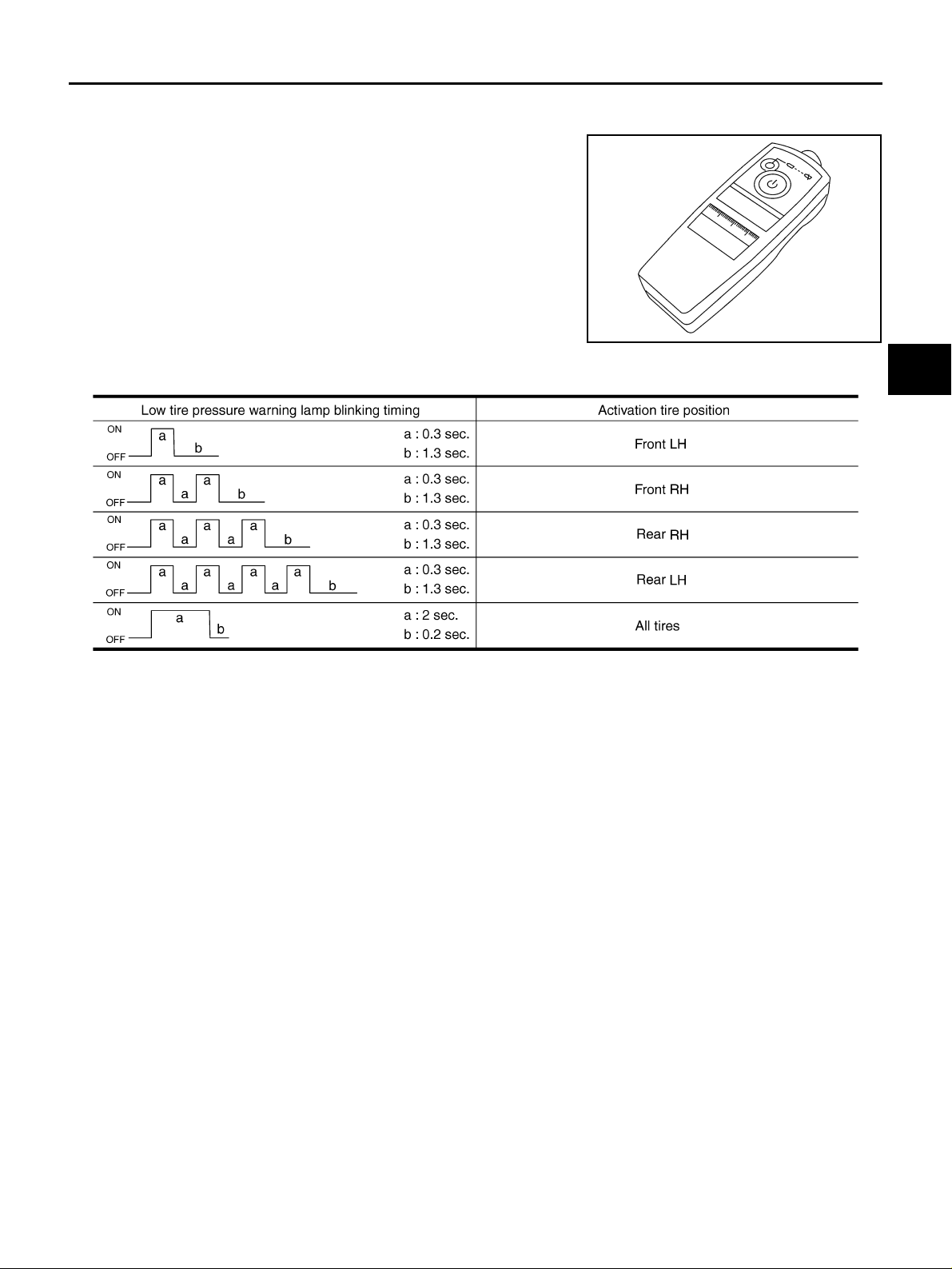
1. With the transmitter activation tool (J-45295) pushed against the
front-left transmitter, press and hold the button for 5 seconds.
● When ignition s witch ON, an d then low tire p ressure warni ng
lamp blinks as per the followin g diagram, t he respec tive then
transmitter must be wake up.
SEIA0460E
A
B
C
D
WT
F
G
SEIA0762E
2. Regist er the ID of w heel that low ti re pressure w arning lamp fl ashes. Whe n wake up of registered wheel
has been completed, hazard warning lamp flashes two times.
3. After completing wake up all transmitters, make sure low tire pressure warning lamp goes out.
H
I
J
K
L
M
Revision: 2005 November 2006 Q45
WT-25
Page 26
TROUBLE DIAGNOSIS
Inspections Before Trouble Diagnosis NES000D0
DIAGNOSTIC PROCEDURE
1. CHECK ALL TIRE PRESSURES
Check all tire pressures. Refer to WT-56, "
Tire" .
OK or NG
OK >> GO TO 2.
NG >> Check the condition of wheels (flat ti re etc.). Then, adjust tire pressure to the spec ified value.
2. CHECK LOW TIRE PRESSURE WARNING LAMP
● Turn ignition sw itch “OFF”.
● Check low tire pressure warning lamp “ON” for approx. 1 second when turned ignition switch “ON”.
Dose low tire pressure warning lamp
“ON” for approx. 1 second?
YES >> GO TO 3.
NO >> Go to WT-40, "
Low Tire Pressure Warning Lamp Does Not Turn ON for Approx.1 Second When
Ignition Switch Is Turned ON" .
3. CHECK LOW TIRE PRESSURE WARNING CONTROL UNIT HARNESS CONNECTOR
1. Disconnect low tire pressure warning control unit harness connector.
2. Check low tire pressure warning control unit pin terminals for damage or loose connection with harness
connector.
OK or NG
OK >> GO TO 4.
NG >> Repair or replace damaged parts.
4. CHECK DTC
Drive at a speed of 40 km/h (25 MPH) or more for several minutes without stopping after perform self-diagnosis. Refer to WT -21, "
Self-Diagnostic Procedure" .
OK or NG
OK >> INSPECTION END
NG >> Perform the self-diagnosis, inspect detected malfunction.
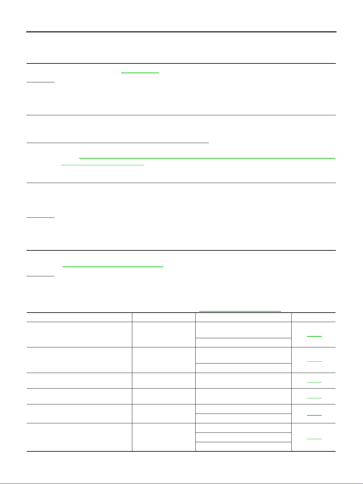
Trouble Diagnosis Chart for Symptoms NES000D3
If low tire pressure warning lamp turns ON, perform self-diagnosis. Refer to WT-21, "Self-Diagnostic Procedure" .
Symptom Condition Check item Reference page
Low tire pressure warning lamp does not
turn ON for approx.1 second when ignition
switch is turned ON.
Low tire pressure warning lamp stays ON
when ignition switch is turned ON.
Low tire pressure warning lamp blinks when
ignition switch is turned ON.
Hazard warning lamp blinks when ignition
switch is turned ON.
“TIRE PRESSURE” information in display
does not exist.
ID registration cannot be completed. Engine running
Ignition ON
Ignition ON
Ignition ON Tire pressure warning check switch WT-44
Ignition ON Combination flasher unit WT-45
Ignition ON
Power supply and ground for low tire
pressure warning control unit
Combination meter
Power supply and ground for low tire
pressure warning control unit
Combination meter
Power supply
Display circuit
Transmitter wake up
ID registration
Transmitter
WT-40
WT-42
WT-46
WT-48
Revision: 2005 November 2006 Q45
WT-26
Page 27
TROUBLE DIAGNOSIS
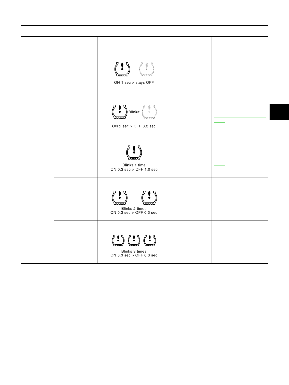
Low Tire Pressure Warning Lamp Symptom Chart NES000DN
Diagnosis
Item
Symptom
(Ignition switch “ON”)
Warning light comes
on immediately and
turns off after 1 second.
Low tire pressure warning lamp Cause Action
All wheel transmitters are “activated”
(working).
SEIA0592E
None (system OK)
A
B
C
D
Low tire pressure warning
lamp
Warning light blinks
on for 2 seconds,
then turns off for 0.2
seconds-repeats.
Warning light blinks 1
time.
Warning light blinks 2
times.
Warning light blinks 3
times.
SEIA0593E
PEIA0073E
SEIA0595E
All wheel transmitters are not activated.
Front LH wheel
transmitter is not
activated.
Front RH wheel
transmitter is not
activated.
Rear RH wheel
transmitter is not
activated.
Activate all wheel transmitters. Refer to WT-25,
"Transmitter Wake Up Operation" .
Activate front LH wheel
transmitter. Refer to WT-25,
"Transmitter Wake Up Operation" .
Activate front RH wheel
transmitter. Refer to WT-25,
"Transmitter Wake Up Operation" .
Activate rear RH wheel
transmitter. Refer to WT-25,
"Transmitter Wake Up Operation" .
WT
F
G
H
I
J
K
L
SEIA0596E
Revision: 2005 November 2006 Q45
WT-27
M
Page 28
TROUBLE DIAGNOSIS
Diagnosis
Item
Low tire pressure warning
lamp
Turn signal
lamp
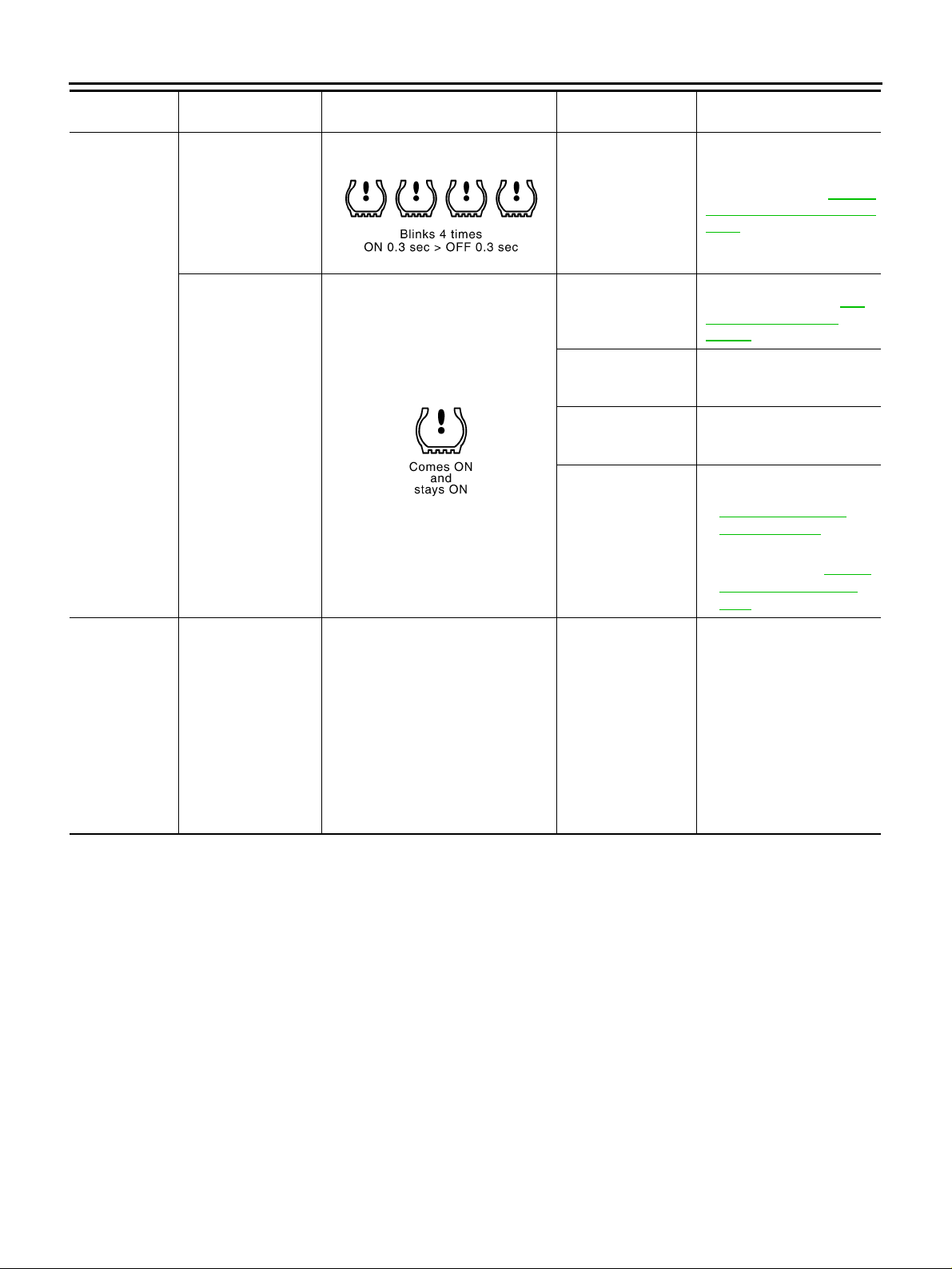
NOTE:
If more than one wheel transmitter is NOT activated, the warning light blinking patterns for those wheels will com bine. (Example: one
blink/“OFF”/three blinks = Rear LH and Rear RH transm itt ers are not act ivat ed. )
Symptom
(Ignition switch “ON”)
Warning light blinks 4
times.
Warning light comes
on and does not turn
off.
Turn signal lamp
does not flash 2
times or buzzer does
not sound after transmitter activation.
Low tire pressure warning lamp Cause Action
Activate rear LH wheel
transmitter. Refer to WT-25,
"Transmitter Wake Up Operation" .
Check tire pressure with
CONSULT-II. Refer to WT-
21, "DATA MONITOR
MODE" .
Check the fuse for combination meter from battery.
Install or replace (if needed).
Check low tire pressure
warning control unit connector. Re-connect if needed.
● Perform CONSULT-I I
Self-Diagnosis. Refer to
WT-19, "
RESULT MODE" .
– Perform ID Registration if
needed. Refer to WT-24,
"ID Registration Procedure" .
1. Install new battery.
2. Make sure ignition is “ON”
during activation.
3. Position tool correctly during activation.
4. None
SELF-DIAG
—
SEIA0597E
SEIA0598E
Rear LH wheel transmitter is not activated.
Tire pressure is low.
The fuse for combination meter from
battery is pulled out.
Low tire pressure
warning control unit
connector pulled out.
Low tire pressure or
low tire pressure
warning system malfunction.
1. Tool J-45295 (special service tool) battery low.
2. Ignition “OFF” during activation.
3. Tool No. J-45295
(special service tool)
not positioned correctly.
4. Transmitters
already activated.
Revision: 2005 November 2006 Q45
WT-28
Page 29
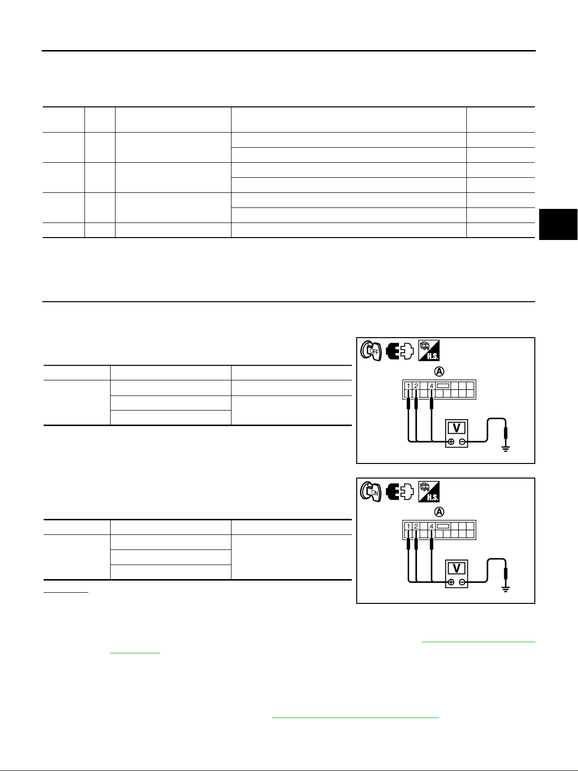
TROUBLE DIAGNOSIS FOR SYSTEM
TROUBLE DIAGNOSIS FOR SYSTEM PFP:00000
Power Supply Circuit NES000D7
LOW TIRE PRESSURE WARNING CONTROL UNIT TERMINALS AND REFERENCE VALUE
Data are reference value and are measured between each terminal and ground.
Terminal
1Y/G
2 BR/W Power supply
4 L/OR Power supply
11 B Ground Always 0 V
CAUTION:
When using a circuit tester to measure voltage for inspection, be sure not to extend forcibly any connector terminals.
Wire
color
Power supply
(Memory back-up)
Item Condition Data (Approx .)
Ignition switch: ON Battery voltage
Ignition switch: OFF Battery voltage
Ignition switch: ON Battery voltage
Ignition switch: OFF 0 V
Ignition switch: ACC Battery voltage
Ignition switch: OFF 0 V
DIAGNOSTIC PROCEDURE
1. CHECK POWER SUPPLY
1. Turn ignition switch “OFF”.
2. Disconnect low tire pressure warning control unit harness connector.
3. Check voltage between low tire pressure warning control unit
harness connector (A) terminals and ground.
A
B
C
D
WT
F
G
H
Connector Terminal Voltage (Approx.)
1 - Ground Battery voltage
M84
2 - Ground
4 - Ground
0 V
4. Turn ign ition switch “ON”. (Do not start engine.)
5. Check voltage between low tire pressure warning control unit
harness connector (A) terminals and ground.
Connector Terminal Voltage (Approx.)
1 - Ground
M84
4 - Ground
Battery voltage2 - Ground
OK or NG
OK >> GO TO 2.
NG >> Check the following. If a ny it ems ar e dam aged , rep air or
replace damaged parts .
● 10A fuses [No. 1, 6, 21 located in the fus e b lock (J/B) No .1] . Refe r to PG-2, "POW ER SUPPLY
ROUTING" .
● Harness for short or open between battery and low tire pressure warning control unit harness
connector M84 terminal 1.
● Harness for short or open between igniti on switch and low tire pre ssure warning control unit
harness connector M84 terminals 2 and 4.
● Battery and ignition swit ch. Refer to PG-2, "POWER SUPPLY ROUTING" .
SEIA0746E
SEIA0747E
I
J
K
L
M
Revision: 2005 November 2006 Q45
WT-29
Page 30
TROUBLE DIAGNOSIS FOR SYSTEM
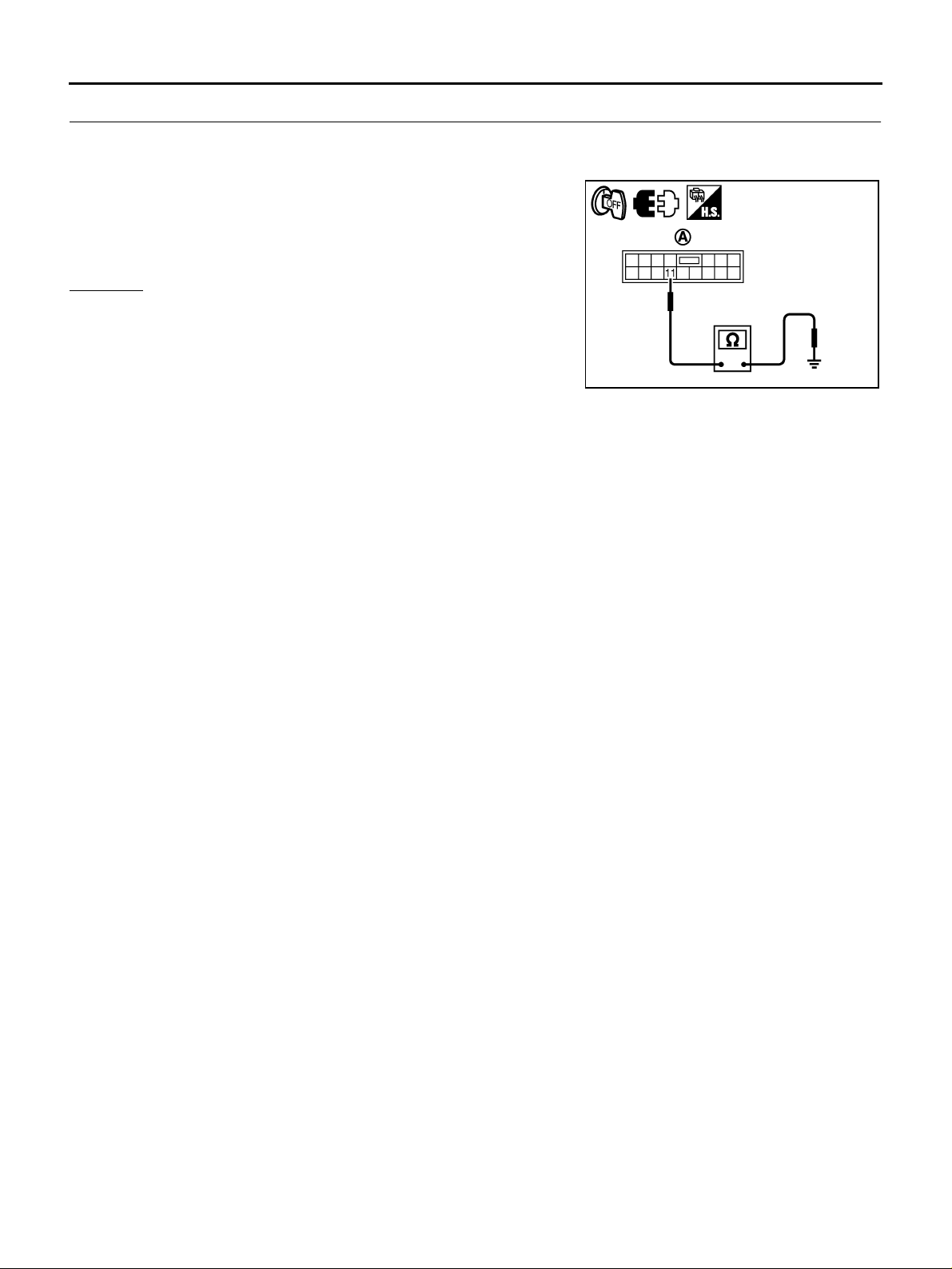
2. CHECK GROUND CIRCUIT
1. Turn ignition switch “OFF”.
2. Disconnect low tire pressure warning control unit harness connector.
3. Check cont inuity betw een low tire pressure w arning contr ol unit
harness connector (A) M84 terminals 11.
Continuity should exist.
Also check harn ess for short to power.
OK or NG
OK >> INSPECTION END
NG >> Repair open circuit or short to power in harn ess or con-
nectors.
SEIA0748E
Revision: 2005 November 2006 Q45
WT-30
Page 31
TROUBLE DIAGNOSIS FOR SYSTEM
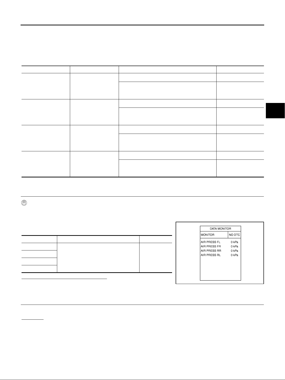
Transmitter (NO DATA) NES000DF
● Check the following if “[NO DATA] FL”, “[NO DATA] FR”, “[NO DATA] RR” or “[NO DATA] RL ” is detected in
self-diagnosis results wit h CONSU LT-II or “flickering pattern fo r 21, 22, 2 3 or 24 ” is det ected in self-dia gnosis results without CONSULT-II.
CONSULT -II REFERENCE VALUE IN DATA MONITOR MODE
Data are reference value.
Monitored item Content Condition Display value
2
, 0 psi)
2
, 0 psi)
2
, 0 psi)
2
, 0 psi)
AIR PRESS FL [kPa],
2
] or [psi]
[kg/cm
AIR PRESS FR [kPa],
2
] or [psi]
[kg/cm
AIR PRESS RR [kPa],
2
] or [psi]
[kg/cm
AIR PRESS RL [kPa],
2
] or [psi]
[kg/cm
Condition of front LH tire
air pressure
Condition of front RH tire
air pressure
Condition of rear LH tire
air pressure
Condition of rear RH tire
air pressure
Just after the engine is started
Start engine and drive at 40 km/h (25 MPH) or more
for several minutes.
Just after the engine is started
Start engine and drive at 40 km/h (25 MPH) or more
for several minutes.
Just after the engine is started
Start engine and drive at 40 km/h (25 MPH) or more
for several minutes.
Just after the engine is started
Start engine and drive at 40 km/h (25 MPH) or more
for several minutes.
0 kPa (0 kg/cm
Approximately equal to
the indication on tire
gauge value
0 kPa (0 kg/cm
Approximately equal to
the indication on tire
gauge value
0 kPa (0 kg/cm
Approximately equal to
the indication on tire
gauge value
0 kPa (0 kg/cm
Approximately equal to
the indication on tire
gauge value
A
B
C
D
WT
F
G
H
DIAGNOSTIC PROCEDURE
1. CHECK AIR PRESSURE SIGNAL
With CONSULT-II
1. Start engine.
2. Select “DATA MONITOR” mode for “AIR PRESSURE MONITOR” with CONSULT-II.
3. Read out the value of “AIR PRESS F L”, “AIR PRESS FR”, “AIR
PRSEE RR” and “AIR PRESS RL”.
Monitored item Condition Display value
AIR PRESS FL
AIR PRESS FR
AIR PRESS RR
AIR PRESS RL
Start engine and drive at 40 km/h (25 MPH)
or more for several minutes.
0 kPa
Are all tire pre s sures displayed 0 kPa?
YES >> GO TO 2.
SEIA0749E
NO >> GO TO 4.
2. CHECK ANTENNA CONNECTOR
Check antenna and feeder connector B183 for damage or loose connections.
OK or NG
OK >> Check low tire pressure warning control unit pin terminals for damage or loose connection with
harness connector. If any items are damaged, repair or replace damaged parts.
NG >> Repair or replace antenna or feeder connector.
I
J
K
L
M
Revision: 2005 November 2006 Q45
WT-31
Page 32
TROUBLE DIAGNOSIS FOR SYSTEM
3. CHECK ID REGISTRATION
Perform the ID registration of all transmitters. Refer to WT-24, "
Can ID registration of all transmitters be completed?
YES >> GO TO 4.
NO >> Replace malfunctioning transmitter the n GO TO 5.
ID Registration Procedure " .
4. CHECK LOW TIRE PRESSURE WARNING SYSTEM
1. Drive at a spee d of 40 km/h (25 MPH) or more for several minutes without stopping.
2. Check all tire pressures with CONSULT-II “DATA MONITOR ITEM” within 15 minutes after vehicle speed
becomes 17 km/h (11 MPH).
“DATA MONITOR ITEM” displayed the standardized value without turning low tire pressure warning
Does
lamp ON?
YES >> INSPECTION END
NO >> Replace low tire pressure warning control unit.
5. CHECK ID REGISTRATION
1. Perform the ID registration of all transmitters. Refer to WT-24, "
2. Drive at a sp eed o f 40 km/h (25 M PH) or mo re for 3 min utes , and then dr ive the v ehicle at any spee d fo r
10 minutes. Then check all tire pressures with CONSULT-II “DATA MONITOR ITEM” within 5 minutes.
Does
“DATA MONITOR ITEM” displayed the standardized value without turning low tire pressure warning
lamp ON?
YES >> INSPECTION END
NO >> Perform the self-diagnosis, inspect detected malfunction.
ID Registration Procedure" .
Revision: 2005 November 2006 Q45
WT-32
Page 33
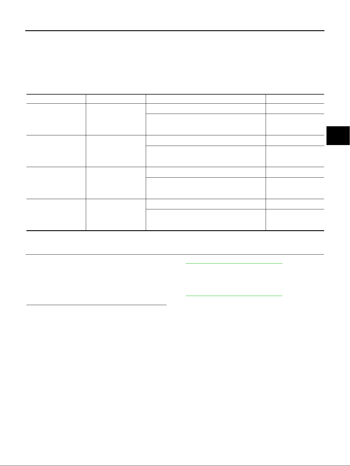
TROUBLE DIAGNOSIS FOR SYSTEM
Transmitter (CHECKSUM ERR, CODE ERR, BATT VOLT LOW) NES000DG
● Check the following if “[CHECKSUM ERR] FL”, “[CHECKSUM ERR] FR”, “[CHECKSUM ERR] RR”,
“[CHECKSUM ERR] RL”, “[CODE ERR] FL”, “[CODE ERR] FR”, “[CODE ERR] RR”, “[CODE ERR] RL”,
“[BATT VOLT LOW] FL”, “[BATT VOLT LOW] FR”, “[BATT VOLT LOW] RR” or “[BATT VOLT LOW] RL” is
detected in se lf-diagnosis res ul ts w ith CO NS ULT-II or “flickering pattern for 31, 32, 33, 34, 41, 42 , 43, 44,
45, 46, 47 or 48” is detected in self-diagnosis results without CONSULT-II.
A
B
CONSULT -II REFERENCE VALUE IN DATA MONITOR MODE
Data are reference value.
Monitored item Content Condition Display value
2
, 0 psi)
2
, 0 psi)
AIR PRESS FL [kPa],
[kg/cm2 ] or [psi]
AIR PRESS FR [kPa],
2
] or [psi]
[kg/cm
AIR PRESS RR [kPa],
2
] or [psi]
[kg/cm
AIR PRESS RL [kPa],
2
] or [psi]
[kg/cm
Condition of front LH tire
air pressure
Condition of front RH tire
air pressure
Condition of rear LH tire
air pressure
Condition of rear RH tire
air pressure
Just after the engine is started
Start engine and drive at 40 km/h (25 MPH) or more
for several minutes.
Just after the engine is started
Start engine and drive at 40 km/h (25 MPH) or more
for several minutes.
Just after the engine is started
Start engine and drive at 40 km/h (25 MPH) or more
for several minutes.
Just after the engine is started
Start engine and drive at 40 km/h (25 MPH) or more
for several minutes.
0 kPa (0 kg/cm
Approximately equal to
the indication on tire
gauge value
0 kPa (0 kg/cm2 , 0 psi)
Approximately equal to
the indication on tire
gauge value
0 kPa (0 kg/cm
Approximately equal to
the indication on tire
gauge value
0 kPa (0 kg/cm2 , 0 psi)
Approximately equal to
the indication on tire
gauge value
DIAGNOSTIC PROCEDURE
1. CHECK ID REGISTRATION
1. Perform the ID registration of all transmitters. Refer to WT-24, "
2. Drive at a speed of 40 km/h (25 MPH) or more for 3 minutes, and then drive the vehicle at any speed for
10 minutes. Then check all tire pressures with CONSULT-II “DATA MONITOR ITEM” within 5 minutes.
3. Perform the self-diagnosis, Replace malfunctioning transmitter.
4. Perform the ID registration of all transmitters. Refer to WT-24, "
Can ID registration of all transmitters be completed.
YES >> GO TO 5.
NO >> GO TO 2.
ID Registration Procedure " .
ID Registration Procedure " .
C
D
WT
F
G
H
I
J
K
L
M
Revision: 2005 November 2006 Q45
WT-33
Page 34
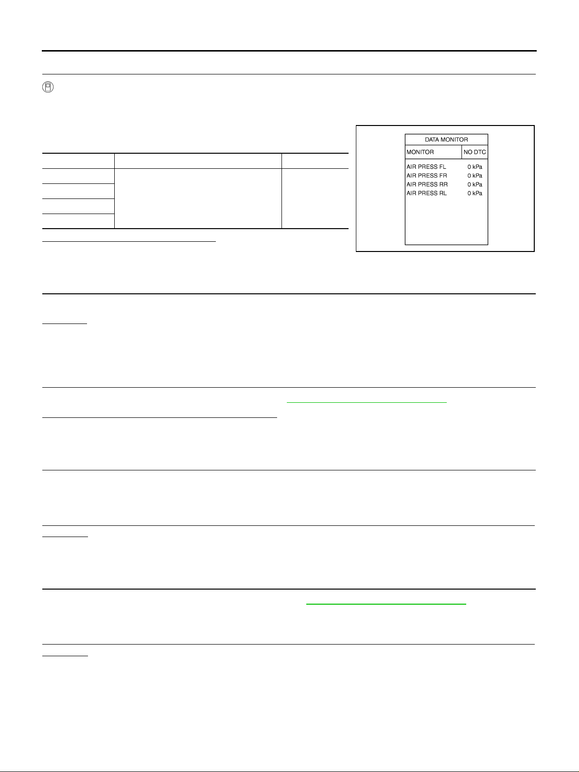
TROUBLE DIAGNOSIS FOR SYSTEM
2. CHECK AIR PRESSURE SIGNAL
With CONSULT-II
1. Start engine.
2. Select “DATA MONITOR” mode for “AIR PRESSURE MONITOR” with CONSULT-II.
3. Read out the value of “AIR PRESS FL”, “AIR PRESS FR”, “AIR
PRSEE RR” and “AIR PRESS RL”.
Monitored item Condition Display value
AIR PRESS FL
AIR PRESS FR
AIR PRESS RR
AIR PRESS RL
Are all tire pre ssures displayed 0 kPa?
YES >> GO TO 3.
NO >> GO TO 5.
Start engine and drive at 40 km/h (25 MPH)
or more for seve r a l minutes.
0 kPa
SEIA0749E
3. CHECK ANTENNA CONNECTOR
Check antenna and feeder connector B183 for damage or loose connections.
OK or NG
OK >> Check low tire pressure warning c ontrol unit pin termin als for damage or loos e connection with
harness connector. If any items are damaged, repair or replace damaged parts.
NG >> Repair or replace antenna or feeder connector.
4. CHECK ID REGISTRATION
Perform the ID registration of all transmitters. Refer to WT-24, "
Can ID registration of all transmitters be completed?
YES >> GO TO 5.
NO >> Replace malfunctioning transmitter the n GO TO 6.
ID Registration Procedure " .
5. CHECK LOW TIRE PRESSURE WARNING SYSTEM
1. Drive at a spee d of 40 km/h (25 MPH) or more for several minutes without stopping.
2. Check all tire pressures with CONSULT-II “DATA MONITOR ITEM” within 15 minutes after vehicle speed
becomes 17 km/h (11 MPH).
Does
“DATA MONITOR ITEM” displayed the standardized value without turning low tire pressure warning
lamp ON?
YES >> INSPECTION END
NO >> Replace low tire pressure warning control unit.
6. CHECK ID REGISTRATION
1. Perform the ID registration of all transmitters. Refer to WT-24, "
2. Drive at a sp eed o f 40 km/h (25 M PH) or mo re for 3 min utes , and then dr ive the v ehicle at any spee d fo r
10 minutes. Then check all tire pressures with CONSULT-II “DATA MONITOR ITEM” within 5 minutes.
“DATA MONITOR ITEM” displayed the standardized value without turning low tire pressure warning
Does
lamp ON?
YES >> INSPECTION END
NO >> GO TO 2.
ID Registration Procedure" .
Revision: 2005 November 2006 Q45
WT-34
Page 35
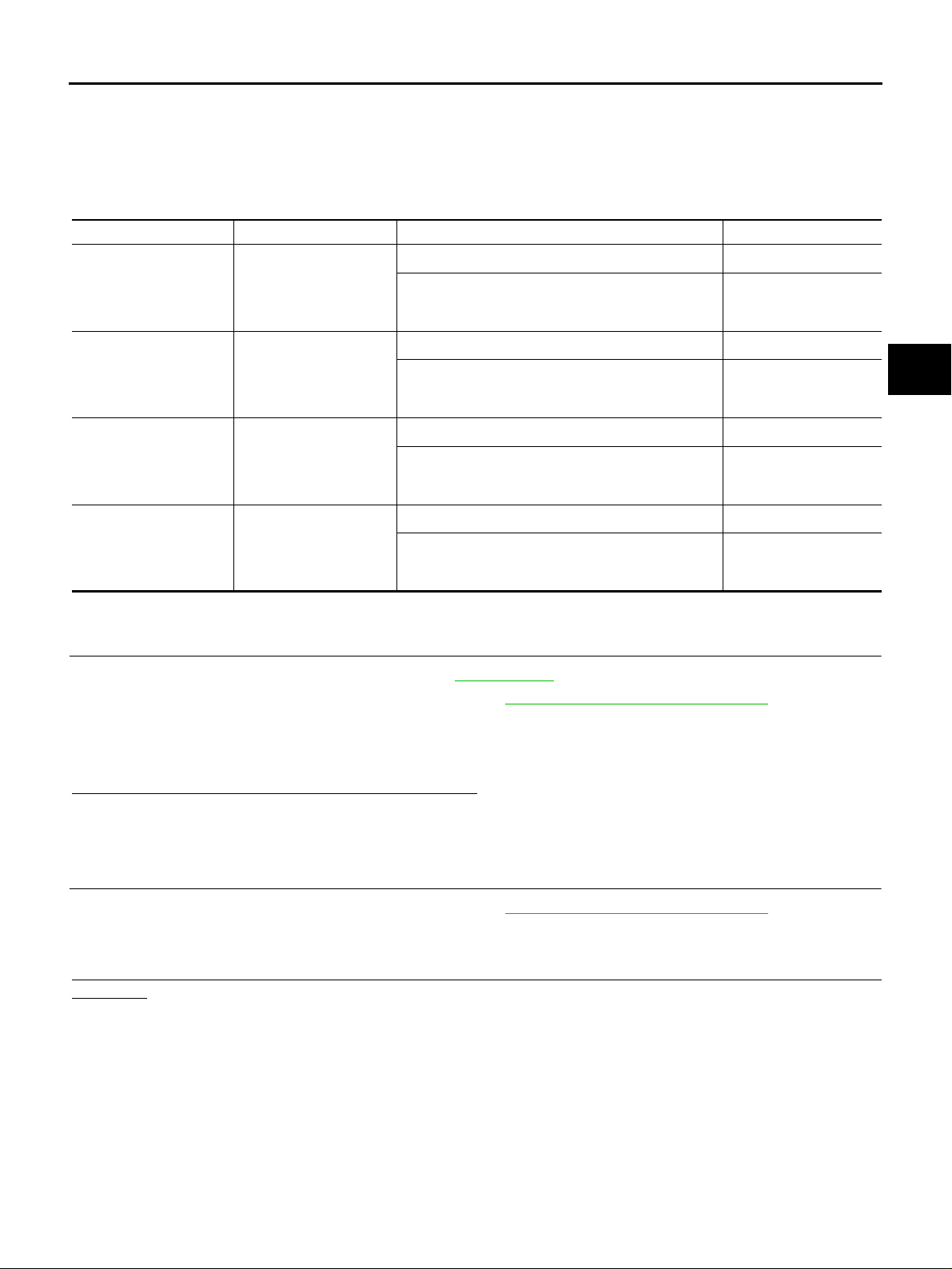
TROUBLE DIAGNOSIS FOR SYSTEM
Transmitter (PRESSDATA ERR) NES0007F
● Check the following if “[PRESSDATA ERR] FL”, “[PRESSDATA ERR] FR”, “[PRESSDATA ERR] RR” or
“[PRESSDATA ERR] RL” is detect ed in self-diagnosis results with CONSULT-II or “flickering pattern for
35, 36, 37 or 38” is detected in self-diagnosis results without CONSULT-II.
CONSULT -II REFERENCE VALUE IN DATA MONITOR MODE
Data are reference value.
Monitored item Content Condition Display value
2
, 0 psi)
2
, 0 psi)
2
, 0 psi)
2
, 0 psi)
AIR PRESS FL [kPa],
2
] or [psi]
[kg/cm
AIR PRESS FR [kPa],
2
] or [psi]
[kg/cm
AIR PRESS RR [kPa],
2
] or [psi]
[kg/cm
AIR PRESS RL [kPa],
2
] or [psi]
[kg/cm
Condition of front LH tire
air pressure
Condition of front RH tire
air pressure
Condition of rear LH tire
air pressure
Condition of rear RH tire
air pressure
Just after the engine is started
Start engine and drive at 40 km/h (25 MPH) or more
for several minutes.
Just after the engine is started
Start engine and drive at 40 km/h (25 MPH) or more
for several minutes.
Just after the engine is started
Start engine and drive at 40 km/h (25 MPH) or more
for several minutes.
Just after the engine is started
Start engine and drive at 40 km/h (25 MPH) or more
for several minutes.
0 kPa (0 kg/cm
Approximately equal to
the indication on tire
gauge value
0 kPa (0 kg/cm
Approximately equal to
the indication on tire
gauge value
0 kPa (0 kg/cm
Approximately equal to
the indication on tire
gauge value
0 kPa (0 kg/cm
Approximately equal to
the indication on tire
gauge value
A
B
C
D
WT
F
G
H
DIAGNOSTIC PROCEDURE
1. CHECK TIRE PRESSURE
1. Adjust tire pressure to specified value. Refer to WT-56, "
2. Perform the ID registration of all transmitters. Refer to WT-24, "
3. Drive at a speed of 40 km/h (25 MPH) or more for several minutes without stopping.
4. Check all tire pressures with CONSULT-II “DATA MONITOR ITEM” within 15 minutes after vehicle speed
become 17 km/h (11 MPH).
What is display CONSULT-II
“DATA MONITOR ITEM”?
438.60 kPa (4.47 kg/cm2 , 63.60 psi)>>Replace malfunctioning transmitter.
Other than 438.60 kPa (4.47 kg/cm
2
, 63.60 psi)>>INSPECTION END
Tire" .
ID Registration Procedure " .
2. CHECK LOW TIRE PRESSURE WARNING SYSTEM
1. Perform the ID registration of all transmitters. Refer to WT-24, "
2. Drive at a speed of 40 km/h (25 MPH) or more for 3 minutes, and then drive the vehicle at any speed for
10 minutes. Then check all tire pressures with CONSULT-II “DATA MONITOR ITEM” within 5 minutes.
Does
“DATA MONITOR ITEM” displayed the standardized value without turning low tire pressure warning
lamp ON?
YES >> INSPECTION END
NO >> Perform the self-diagnosis, inspect detected malfunction.
ID Registration Procedure " .
I
J
K
L
M
Revision: 2005 November 2006 Q45
WT-35
Page 36
TROUBLE DIAGNOSIS FOR SYSTEM
Ve hicle Speed Signal NES0007G
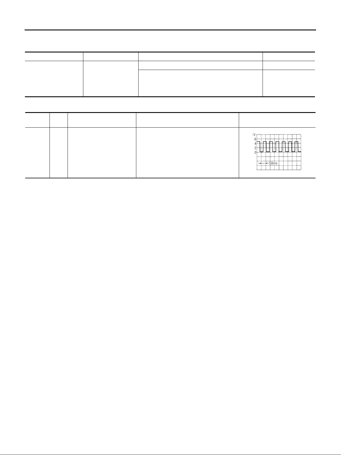
CONSULT-II REFERENCE VALUE IN DATA MONITOR MODE
Data are reference value.
Monitored item Content Condition Display value
Vehicle stopped 0 km/h (0 MPH)
VHCL SPEED SE [km/h]
or [mph]
Wheel speed
Vehicle running
CAUTION:
Check air pressure of tire under standard condition.
LOW TIRE PRESSURE WARNING CONTROL UNIT TERMINALS AND REFERENCE VALUE
Data are reference value and are measured betwee n each t erm inal and gr ound.
Terminal
10 OR/L Vehicle speed Vehicle speed: 40 km/h (25 MPH)
CAUTION:
When using a oscilloscope to measure voltage for inspection, be sure not to extend forcibly any connector terminal.
Wire
color
Item Condition Data (Approx.)
Approximately equal
to the indic ation on
speedometer (Inside
of ±10%)
ELF1080D
Revision: 2005 November 2006 Q45
WT-36
Page 37
TROUBLE DIAGNOSIS FOR SYSTEM
DIAGNOSTIC PROCEDURE
1. CHECK VEHICLE SPEED SENSOR
A
With CONSULT-II
1. Start engine.
2. Select “DATA MONITOR” mode for “AIR PRESSURE MONITOR” with CONSULT-II.
3. Read out the value of “VHCL SPEED SE”.
Condition Display value
Vehicle stopped 0 km/h (0 MPH)
Vehicle running
CAUTION:
Check air pressure of tire under standard condition.
Approximately equal to
the indication on speedometer (Inside of ±10%)
Without CONSULT-II
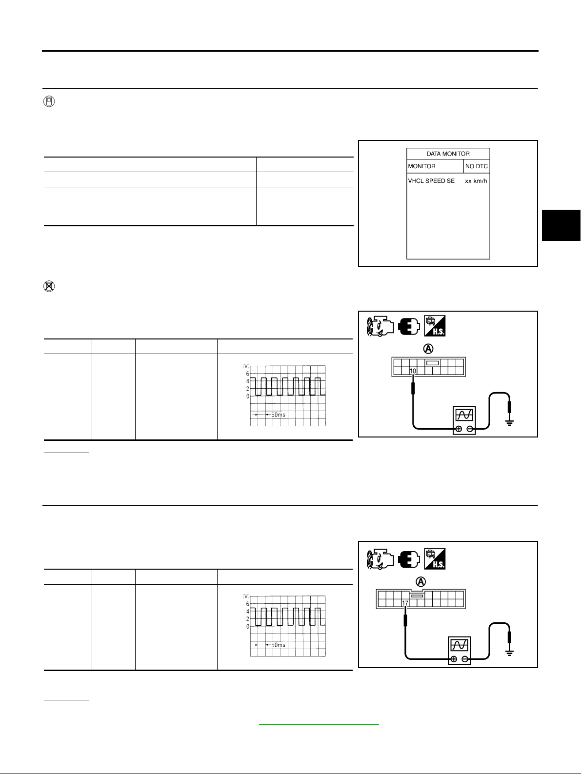
1. Start engine.
2. Check signal between low tire pressure warning control unit harness connector (A) terminal and ground with oscilloscope.
Connector Terminal Condition Data (Approx.)
M84
10 -
Ground
Vehicle speed:
40 km/h (25 MPH)
SGIA1404E
B
C
D
WT
F
G
H
I
ELF1080D
OK or NG
OK >> GO TO 4.
NG >> GO TO 2.
2. CHECK COMBINA TION METER
1. Turn ignition switch “OFF”.
2. Disconnect low tire pressure warning control unit harness connector.
3. Check signal between combination meter harness connector (A)
terminal and ground with oscilloscope.
Connector Terminal Condition Data (Approx.)
M41
17 -
Ground
Also check harness for short to ground and short to power.
OK or NG
OK >> GO TO 3.
NG >> Check combination meter. Refer to DI-16, "
Vehicle speed:
40 km/h (25 MPH)
ELF1080D
Trouble Diagnosis" .
J
SEIA0763E
K
L
M
SEIA0764E
Revision: 2005 November 2006 Q45
WT-37
Page 38
TROUBLE DIAGNOSIS FOR SYSTEM
3. CHECK HARNESS BETWEEN LOW TIRE PRESSURE WARNING CONTROL UNIT AND COMBINA-
TION METER
1. Turn ignition switch “OFF”.
2. Disconnect low tire pressure warning control unit harness connector and the combination meter harness
connector.
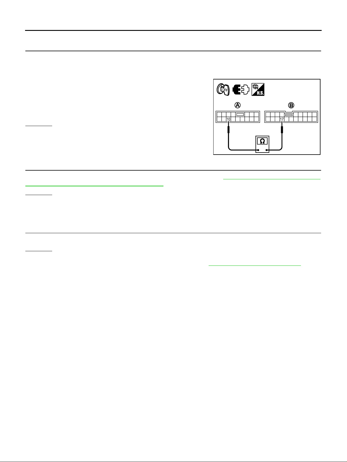
3. Check cont inuity betw een low tire pressure w arning contr ol unit
harness connector (A) M84 terminal 10 and combination meter
harness connector (B) M41 terminal 17.
Continuity should exist.
Also check harness for short to ground and short to power.
OK or NG
OK >> GO TO 4.
NG >> Repair or replace damaged parts.
SEIA0765E
4. CHECK LOW TIRE PRESSURE WARNING CONTROL UNIT
Check low tire pre ssur e warnin g co ntrol u nit inpu t/outp ut si gnal . Ref er to WT-17, "
Control Unit Input/Output Signal Reference Values" .
OK or NG
OK >> GO TO 5.
NG >> Check low tire pressure w arning control unit pi n terminals for dama ge or loose connectio n with
harness connector. If any items are damaged, repair or replace damaged parts.
Low Tire Pressure Warning
5. CHECK DTC
Perform the self-diagnosis, after driving a vehicle for a while.
OK or NG
OK >> INSPECTION END
NG >> Replace low tire pressure warning control unit. Refer to WT-49, "
Removal and Installatio n" .
Revision: 2005 November 2006 Q45
WT-38
Page 39
TROUBLE DIAGNOSIS FOR SYSTEM
Component Inspection NES000HK
COMBINATION FLASHER UNIT
1. Turn ignition switch “OFF”.
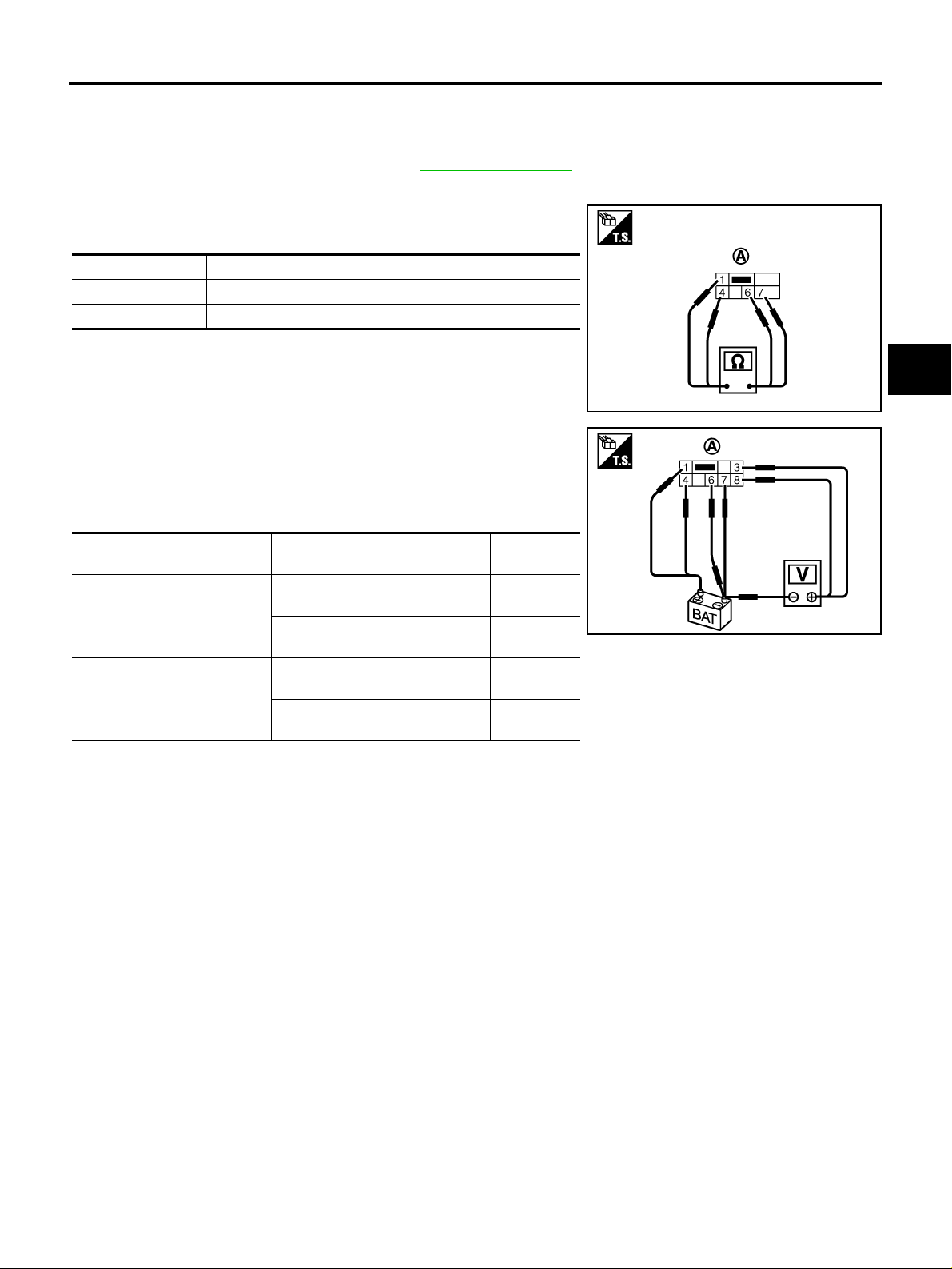
2. Remove combination flasher unit. Refer to WT-50, "
3. Check resistance between the following terminals.
● Combination flasher unit connector (A) terminals 1 and 7.
● Combination flasher unit connector (A) terminals 4 and 6.
Terminal Resistance (Approx.)
1 – 7 89 kΩ
4 – 6 78 Ω
REMOVAL" .
SEIA0785E
A
B
C
D
WT
4. Apply 12 V direct current to combination flasher unit connector
(A) terminals 1 and 4 (positive), and to terminals 6 and 7 (negative).
5. Check voltege between combination flasher unit connector (A)
terminals 3, 8 (positive) and battery (negative).
Terminal Condition
3 (positive) – battery (negative)
8 (positive) – battery (negative)
With terminal 6 connected with
negative terminal of battery.
Without terminal 6 connected with
negative terminal of battery.
With terminal 6 connected with
negative terminal of battery.
Without terminal 6 connected with
negative terminal of battery.
Voltege
(Approx.)
6 V
0 V
6 V
0 V
6. If NG, replace combination flasher unit.
SEIA0786E
F
G
H
I
J
K
L
M
Revision: 2005 November 2006 Q45
WT-39
Page 40
TROUBLE DIAGNOSIS FOR SYMPTOMS
TROUBLE DIAGNOSIS FOR SYMPTOMS PFP:00007
Low Tire Pressure Warning Lamp Does Not Turn ON for Approx.1 Second When
Ignition Switch Is Turned ON
DIAGNOSTIC PROCEDURE
NES0007H
1. CHECK COMBINATION METER POWER SUPPLY CIRCUIT
1. Turn ignition switch “OFF”.
2. Disconnect combination meter harness connector.
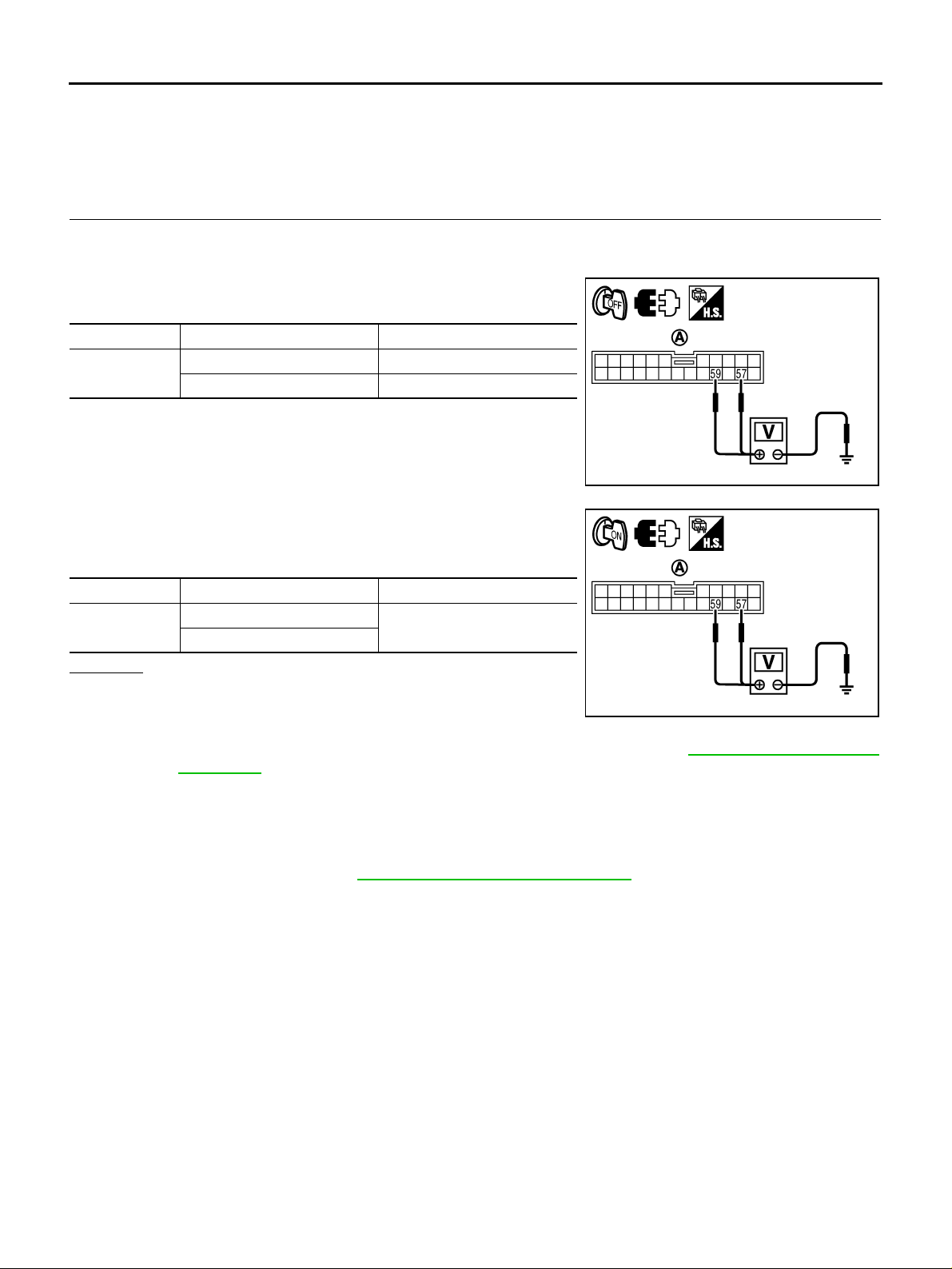
3. Check voltage between combination meter harness connector
(A) terminal and ground.
Connector Terminal Voltage (Approx.)
M43
57 - Ground Battery voltage
59 - Ground 0 V
SEIA0773E
4. Turn ignition switch “ON”. (Do not start engine.)
5. Check voltage between combination meter harness connector
(A) terminal and ground.
Connector Terminal Voltage (Approx.)
M43
57 - Ground
59 - Ground
Battery voltage
OK or NG
OK >> GO TO 2.
NG >> Check the following. I f any i tems are da mage d, rep air or
replace damaged parts.
● 10A fuse [No. 6 , 9, located in the fuse block (J/B) No.1]. Re fer to PG-2, "POWER SUPPLY
ROUTING" .
● Harness for sho rt or open betwe en bat tery an d com binat ion me ter harnes s con nector M4 3 ter -
minal 57.
● Harness for short or open between ignition switch and combination meter harness connector
M43 terminal 59.
● Ignition switch. Refer to PG-2, "POWER SUPPLY ROUTING" .
SEIA0774E
Revision: 2005 November 2006 Q45
WT-40
Page 41
TROUBLE DIAGNOSIS FOR SYMPTOMS
2. CHECK HARNESS BETWEEN LOW TIRE PRESSURE WARNING CONTROL UNIT AND COMBINA-
TION METER
1. Turn ignition switch “OFF”.
2. Disconnect combination meter harness connector and low tire pressure warning control unit harness connector.
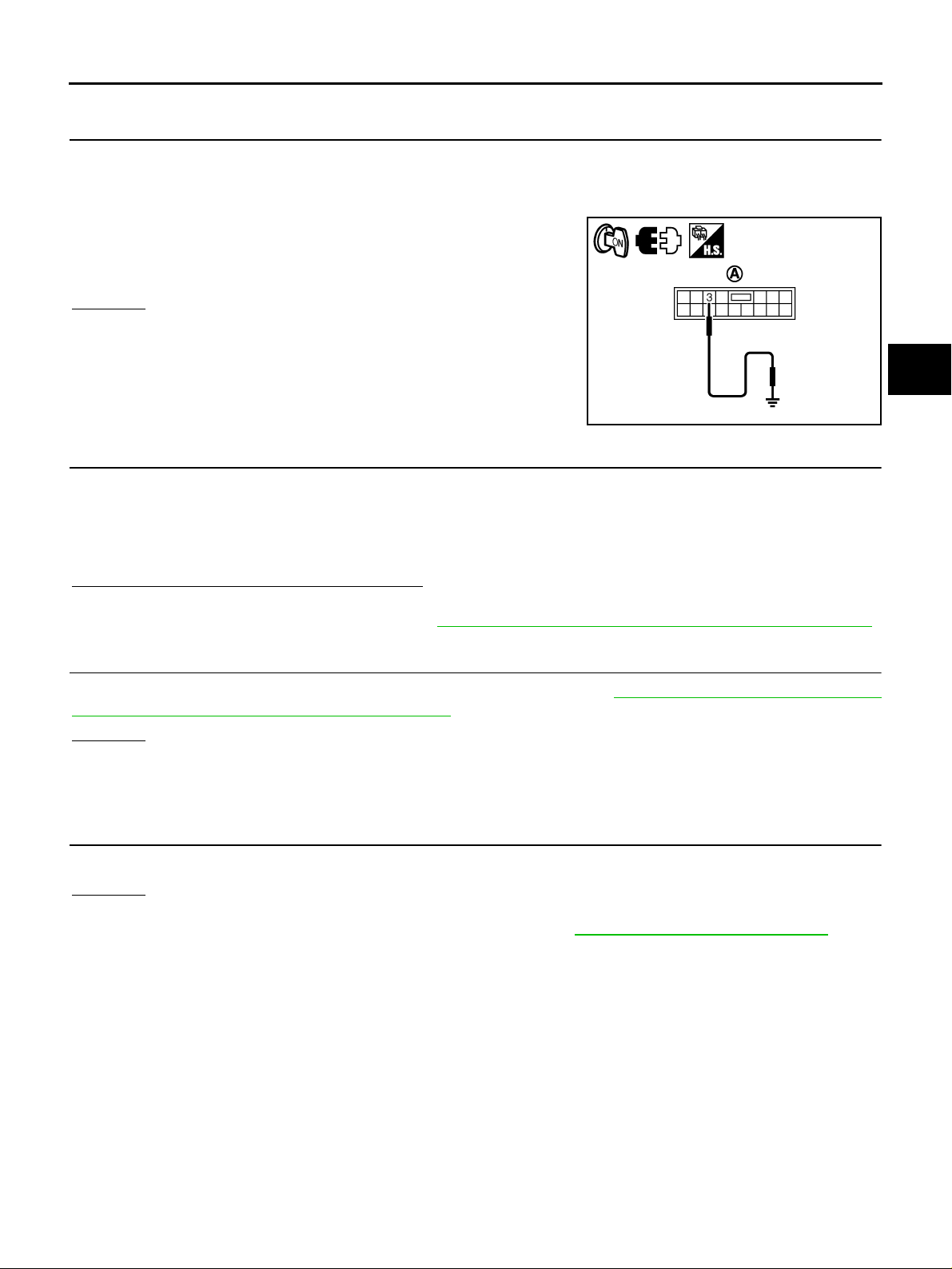
3. Check continuit y between l ow tire press ure warning c ontrol uni t
harness connector (A) M84 terminal 3 and grou nd.
Continuity should no exist.
OK or NG
OK >> GO TO 3.
NG >> Repair short to ground in harness or connector.
SEIA0751E
3. CHECK LOW TIRE PRESSURE WARNING LAMP
1. Turn ignition switch “OFF”.
2. Connect combination meter harness connector.
3. Disconnect low tire pressure warning control unit harness connector.
4. Turn ign ition switch “ON”. (Do not start engine.)
Does low tire pressure warning lamps turn ON?
OK >> GO TO 4.
NG >> Replace combination mete r. Refer to DI-24, "
Disassembly an d Assembl y for Combin atio n Meter " .
A
B
C
D
WT
F
G
H
I
4. CHECK LOW TIRE PRESSURE WARNING CONTROL UNIT
Check low tire pres sure warnin g contro l unit input /outp ut sig nal. Refer to WT-17, "
Control Unit Input/Output Signal Reference Values" .
OK or NG
OK >> GO TO 5.
NG >> Check low tire pressure warning control unit pin terminals for damage or loose connection with
harness connector. If any items are damaged, repair or replace damaged parts.
Low Tire Pressure Warning
5. CHECK SYMPTOM
Check again.
OK or NG
OK >> INSPECTION END
NG >> Replace low tire pressure warning control unit. Refer to WT-49, "
Removal and Installation" .
J
K
L
M
Revision: 2005 November 2006 Q45
WT-41
Page 42
TROUBLE DIAGNOSIS FOR SYMPTOMS
Low Tire Pressure Warning Lamp Stays ON When Ignition Switch Is Turned ON
NES0007I
DIAGNOSTIC PROCEDURE
1. CHECK SYSTEM FOR LOW TIRE PRESSURE WARNING CONTROL UNIT
Perform self-diagnosis. Refer to WT-21, "
Does the self-diagnostic results indicate any malfunctions?
YES >> Perform trouble diagnosis. Refer to WT-19, "SELF-DIAG RESULT MODE" .
NO >> GO TO 2.
Self-Diagnostic Procedure" .
2. CHECK POWER SUPPLY
1. Turn ignition switch “OFF”.
2. Disconnect low tire pressure warning control unit harness connector.
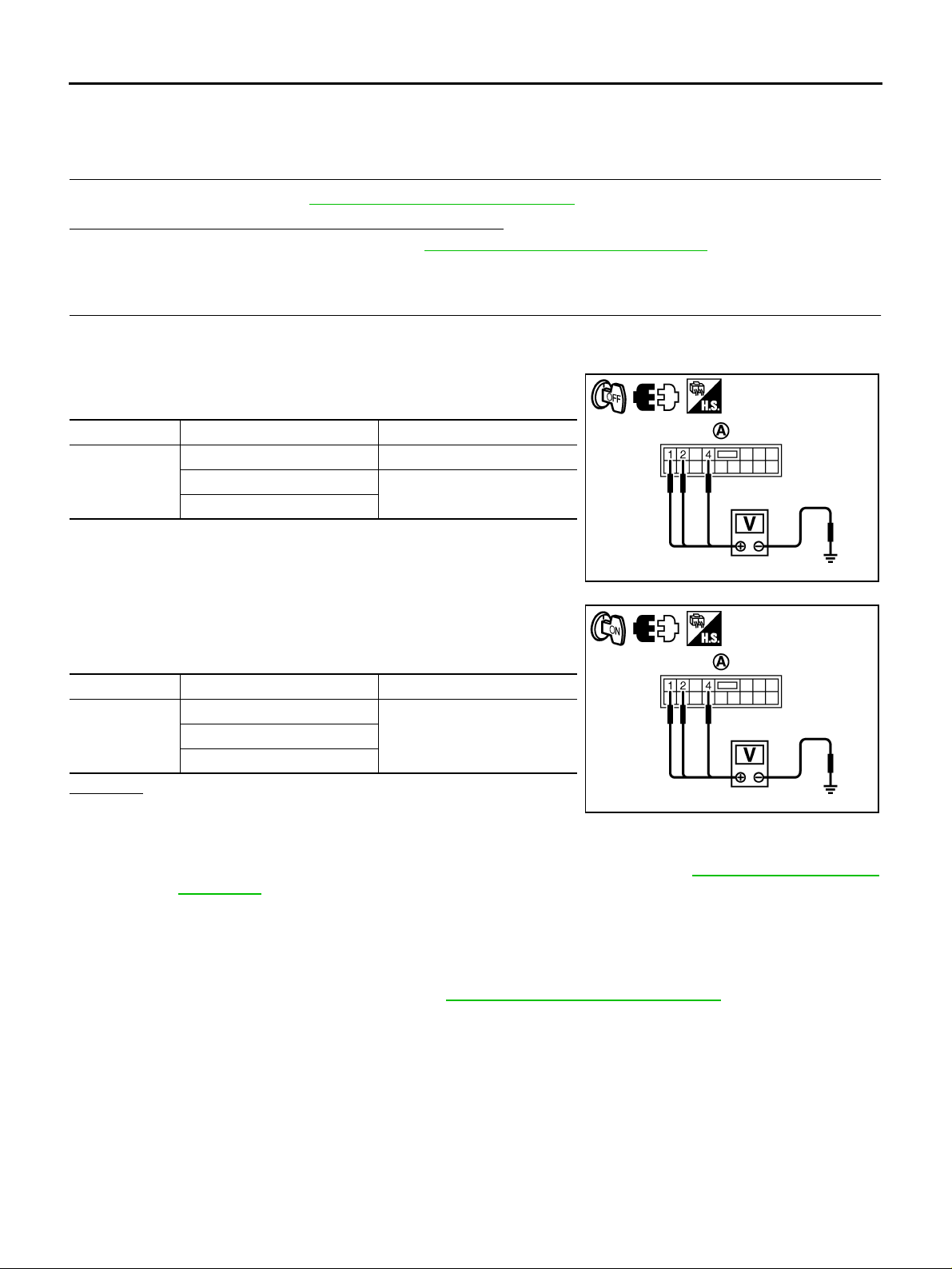
3. Check voltage between low tire pressure warning control unit
harness connector (A) terminals and ground.
Connector Terminal Voltage (Approx.)
1 - Ground Batte ry voltage
M84
2 - Ground
4 - Ground
0 V
4. Turn ignition switch “ON”. (Do not start engine.)
5. Check voltage between low tire pressure warning control unit
harness connector (A) terminals and ground.
Connector Terminal Voltage (Approx.)
1 - Ground
M84
4 - Ground
Battery voltage2 - Ground
OK or NG
OK >> GO TO 3.
NG >> Check the following. I f any i tems are da mage d, rep air or
replace damaged parts.
● 10A fuses [No. 1, 6, 21 located in the fuse block (J/B) No.1]. Refer to PG-2 , "POWER SUPPLY
ROUTING" .
● Harness for short or open between battery and low tire pressure warning control unit harness
connector M84 terminal 1.
● Harness for short or open between ignition switch and low tire pressure warning control unit
harness connector M84 terminals 2 and 4.
● Battery and ignition switch. Refer to PG-2, "POWER SUPPLY ROUTING" .
SEIA0746E
SEIA0747E
Revision: 2005 November 2006 Q45
WT-42
Page 43
TROUBLE DIAGNOSIS FOR SYMPTOMS
3. CHECK GROUND CIRCUIT
1. Turn ignition switch “OFF”.
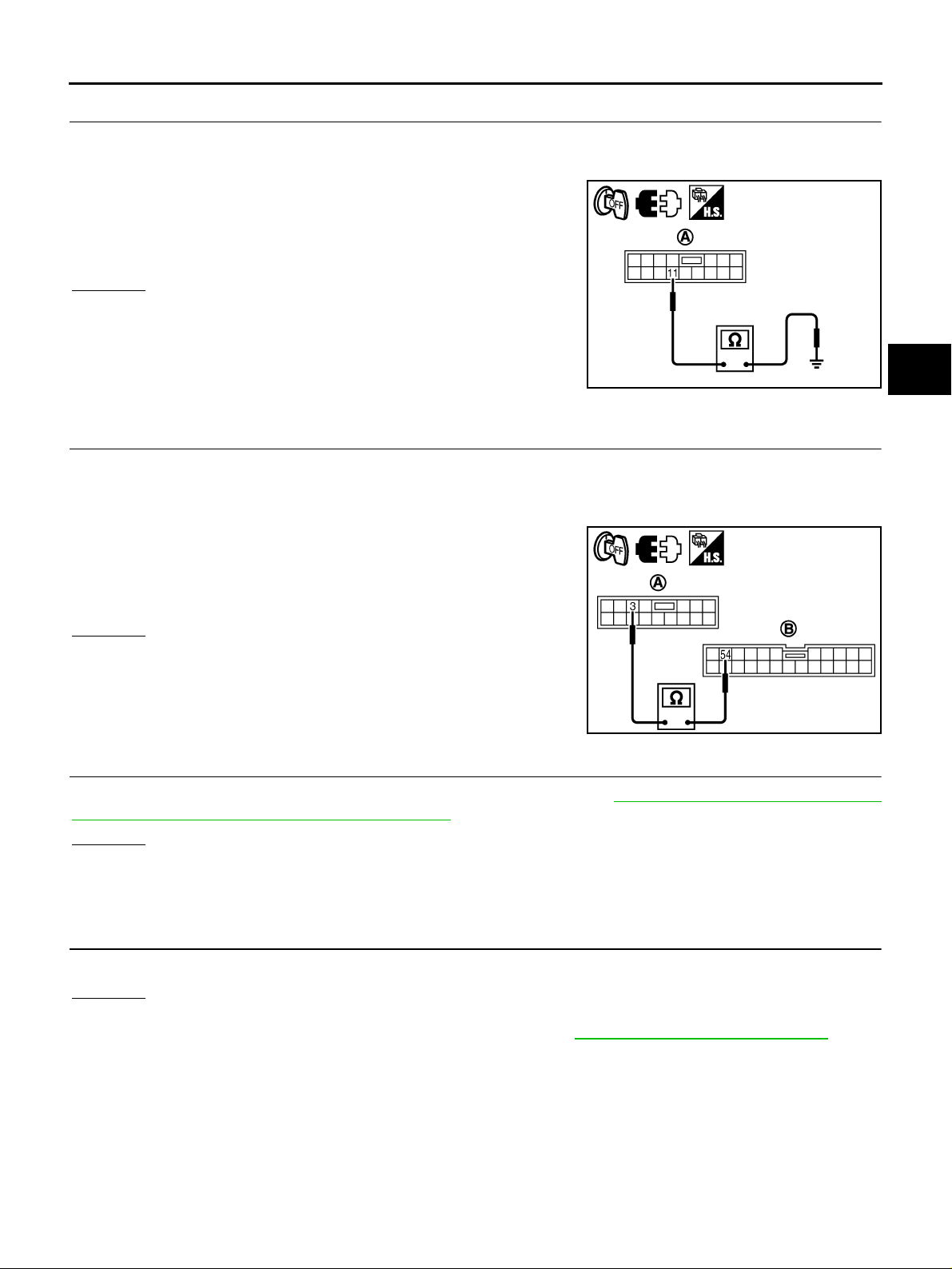
2. Disconnect low tire pressure warning control unit harness connector.
3. Check continuit y between l ow tire press ure warning c ontrol uni t
harness connector (A) M84 terminals 11.
Continuity should exist.
Also check harness for short to power.
OK or NG
OK >> GO TO 4.
NG >> Repair open circuit or short to power in harness or con-
nectors.
SEIA0748E
4. CHECK HARNESS BETWEEN LOW TIRE PRESSURE WARNING CONTROL UNIT AND COMBINA-
TION METER
1. Turn ignition switch “OFF”.
2. Disconnect combination meter harness connector and low tire pressure warning control unit harness connector.
3. Check continuit y between l ow tire press ure warning c ontrol uni t
harness connector (A) M84 terminal 3 and combination meter
harness connector (B) M43 terminal 54.
A
B
C
D
WT
F
G
H
Continuity should exist.
OK or NG
OK >> GO TO 5.
NG >> Repair open circuit in harness or connectors.
SEIA0750E
5. CHECK LOW TIRE PRESSURE WARNING CONTROL UNIT
Check low tire pres sure warnin g contro l unit input /outp ut sig nal. Refer to WT-17, "
Control Unit Input/Output Signal Reference Values" .
OK or NG
OK >> GO TO 6.
NG >> Check low tire pressure warning control unit pin terminals for damage or loose connection with
harness connector. If any items are damaged, repair or replace damaged parts.
Low Tire Pressure Warning
6. CHECK SYMPTOM
Check again.
OK or NG
OK >> INSPECTION END
NG >> Replace low tire pressure warning control unit. Refer to WT-49, "
Removal and Installation" .
I
J
K
L
M
Revision: 2005 November 2006 Q45
WT-43
Page 44
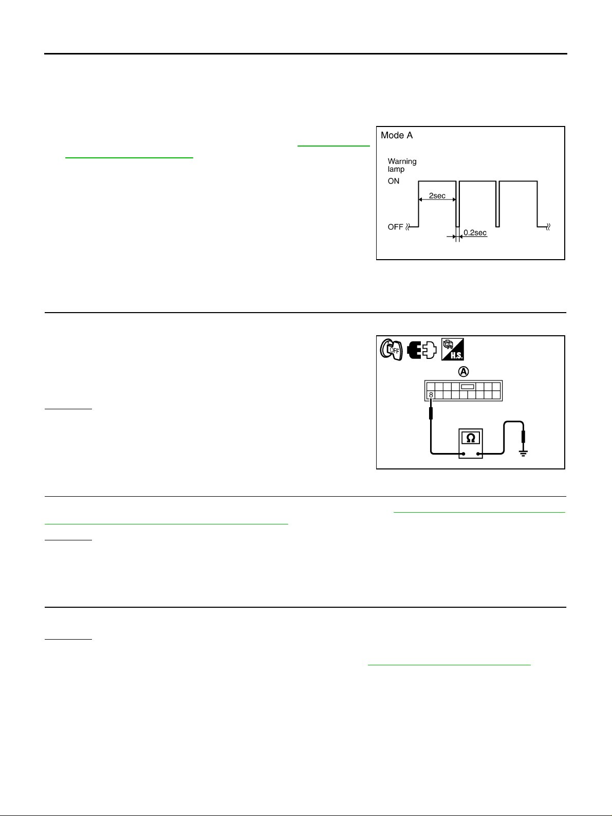
TROUBLE DIAGNOSIS FOR SYMPTOMS
Low Tire Pressure Warning Lamp Blinks When Ignition Switch Is Turned ON
SYMPTOM:
If warning lamp blinks below, the system is normal.
Blink Mode A
● This mode shows transmitter status is OFF-mode.
Perform transmitter w ake up operat ion. Ref er to WT-25, "
mitter Wake Up Operation" .
Trans-
SEIA0347E
DIAGNOSTIC PROCEDURE
1. CHECK TIRE PRESSURE WARNING CHECK SWITCH CIRCUIT
1. Turn ignition switch “OFF”.
2. Disconnect low tire pressure warning control unit connector.
3. Check cont inuity betw een low tire pressure w arning contr ol unit
harness connector (A) M84 termi nal 8 and ground.
NES0007J
Continuity should not exist.
OK or NG
OK >> GO TO 2.
NG >> Repair short to ground in harness or connector.
SEIA0752E
2. CHECK LOW TIRE PRESSURE WARNING CONTROL UNIT
Check low tire pre ssur e warnin g co ntrol u nit inpu t/outp ut si gnal . Ref er to WT-17, "
Control Unit Input/Output Signal Reference Values" .
OK or NG
OK >> GO TO 3.
NG >> Check low tire pressure w arning control unit pi n terminals for dama ge or loose connectio n with
harness connector. If any items are damaged, repair or replace damaged parts.
Low Tire Pressure Warning
3. CHECK SYMPTOM
Check again.
OK or NG
OK >> INSPECTION END
NG >> Replace low tire pressure warning control unit. Refer to WT-49, "
Removal and Installatio n" .
Revision: 2005 November 2006 Q45
WT-44
Page 45

TROUBLE DIAGNOSIS FOR SYMPTOMS
Hazard Warning Lamp Blinks When Ignition Switch Is Turned ON NES0007 K
DIAGNOSTIC PROCEDURE
1. CHECK LOW TIRE PRESSURE WARNING CONTROL UNIT CIRCUIT
A
1. Turn ignition switch “OFF”.
2. Disconnect low tire pressure warning control unit harness connector.
3. Turn ign ition switch “ON”. (Do not start engine.)
Does hazard warning lamp blinks?
YES >> Check the following. If any items are damaged, repair or replace damaged parts.
● Harness for short to ground between combination flasher unit harness connector M91 terminal
6 and low tire pressure warning control unit harness connector M84 terminal 9.
● Combination flasher unit.
NO >> GO TO 2.
2. CHECK LOW TIRE PRESSURE WARNING CONTROL UNIT
Check low tire pres sure warnin g contro l unit input /outp ut sig nal. Refer to WT-17, "
Control Unit Input/Output Signal Reference Values" .
OK or NG
OK >> GO TO 3.
NG >> Check low tire pressure warning control unit pin terminals for damage or loose connection with
harness connector. If any items are damaged, repair or replace damaged parts.
Low Tire Pressure Warning
3. CHECK SYMPTOM
Check again.
OK or NG
OK >> INSPECTION END
NG >> Replace low tire pressure warning control unit. Refer to WT-49, "
Removal and Installation" .
B
C
D
WT
F
G
H
I
J
K
M
L
Revision: 2005 November 2006 Q45
WT-45
Page 46
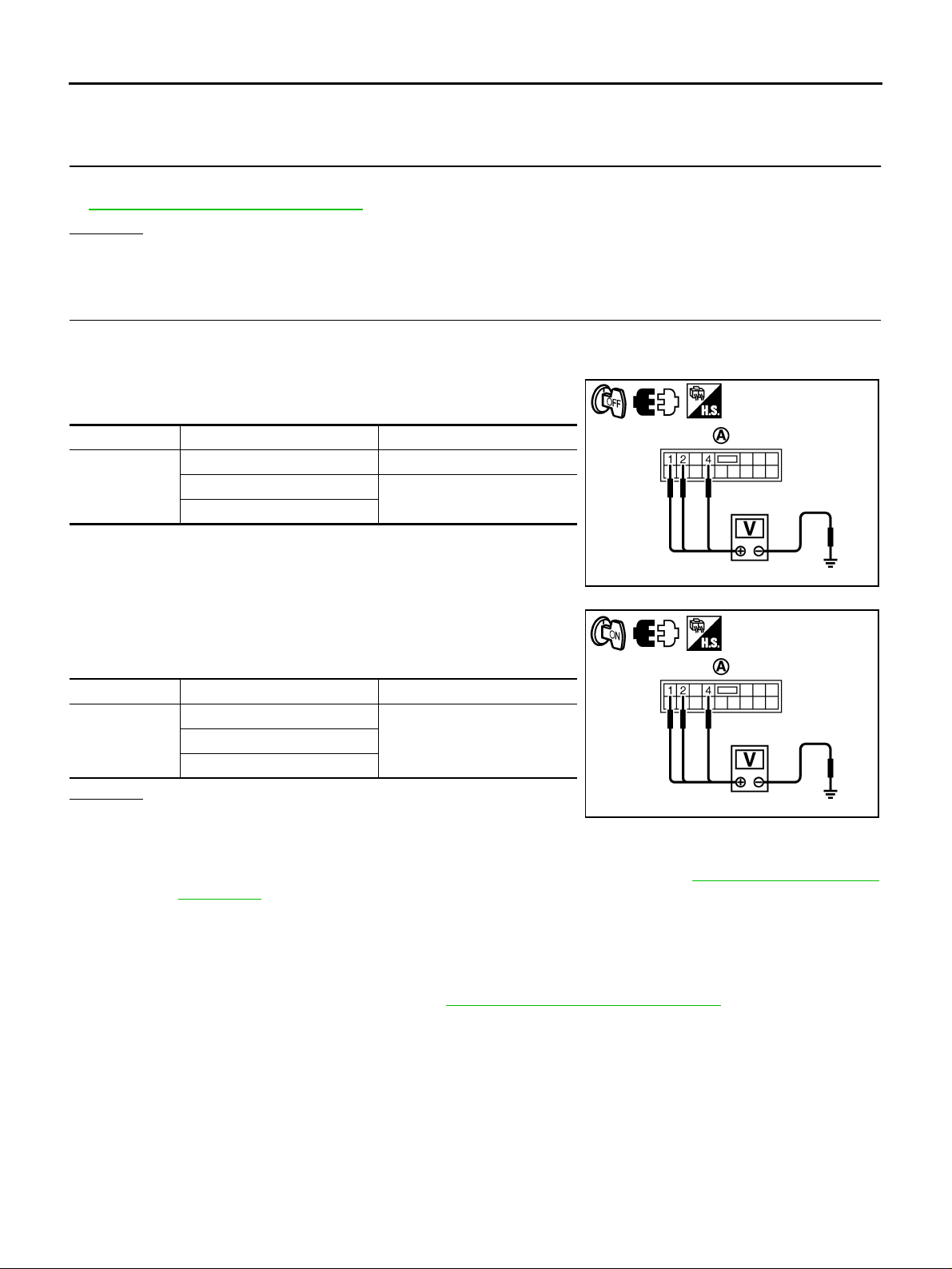
TROUBLE DIAGNOSIS FOR SYMPTOMS
“TIRE PRESSURE” Information In Display Does Not Exist NES0007L
DIAGNOSTIC PROCEDURE
1. CHECK FUSE
Check 10A fuses [ No. 21 located in th e fuse block (J/B) No.1 ] for low tire press ure wa rnin g co nt rol u nit . Re fe r
to PG-2, "
POWER SUPPLY ROUTING" .
OK or NG
OK >> GO TO 3.
NG >> GO TO 2.
2. CHECK POWER SUPPLY
1. Turn ignition switch “OFF”.
2. Disconnect low tire pressure warning control unit harness connector.
3. Check voltage between low tire pressure warning control unit
harness connector (A) terminals and ground.
Connector Terminal Voltage (Approx.)
1 - Ground Batte ry voltage
M84
2 - Ground
4 - Ground
0 V
4. Turn ignition switch “ON”. (Do not start engine.)
5. Check voltage between low tire pressure warning control unit
harness connector (A) terminals and ground.
Connector Terminal Voltage (Approx.)
1 - Ground
M84
4 - Ground
Battery voltage2 - Ground
OK or NG
OK >> GO TO 3.
NG >> Check the following. I f any i tems are da mage d, rep air or
replace damaged parts.
● 10A fuses [No. 1, 6, 21 located in the fuse block (J/B) No.1]. Refer to PG-2 , "POWER SUPPLY
ROUTING" .
● Harness for short or open between battery and low tire pressure warning control unit harness
connector M84 terminal 1.
● Harness for short or open between ignition switch and low tire pressure warning control unit
harness connector M84 terminals 2 and 4.
● Battery and ignition switch. Refer to PG-2, "POWER SUPPLY ROUTING" .
SEIA0746E
SEIA0747E
Revision: 2005 November 2006 Q45
WT-46
Page 47
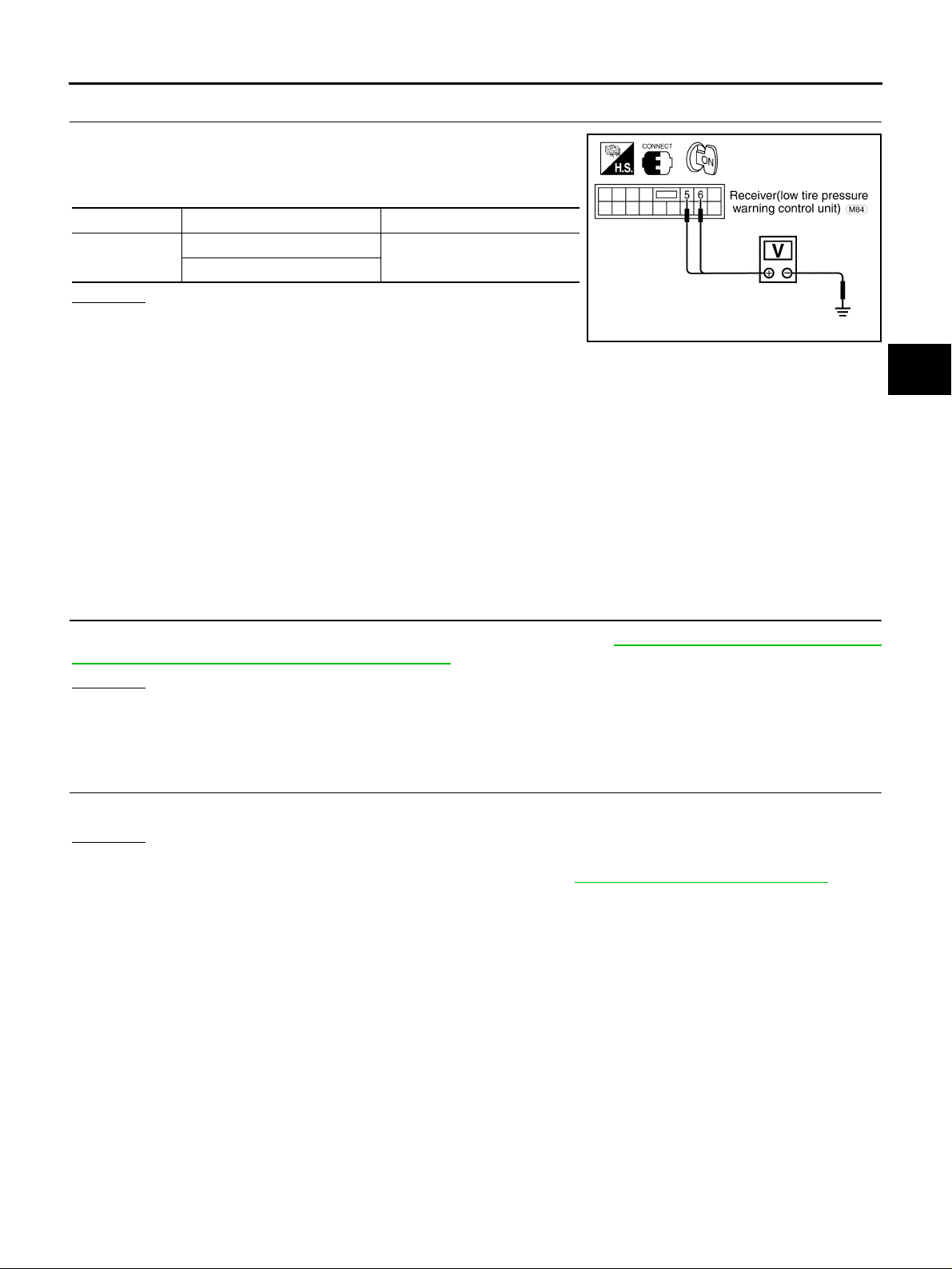
TROUBLE DIAGNOSIS FOR SYMPTOMS
3. CHECK LOW TIRE PRESSURE WARNING CONTROL UNIT SIGNAL
1. Turn ign ition switch “ON”. (Do not start engine.)
2. Check voltage between low tire pressure warning control unit
harness connector termina l and ground.
Connector Terminal Voltage (Approx.)
M84
5 - Ground
6 - Ground
OK or NG
OK >> GO TO 4.
NG >> Check the following. If a ny it ems ar e dam aged , rep air or
replace damaged parts .
● Harness for open o r sh ort be tw ee n low tire pre s su re c on tro l u ni t h arn es s c o nn ec tor M84 termi-
nal 5 and multi function switch harness connector M83 termina l 15.
● Harness for open o r sh ort be tw ee n low tire pre s su re c on tro l u ni t h arn es s c o nn ec tor M84 termi-
nal 6 and multi function switch harness connector M83 termina l 16.
● Harness for open or short between display harness connector M82 terminal 16 and multifunc-
tion switch harness connector M83 terminal 9.
● Harness for open or short between display harness connector M82 terminal 15 and multifunc-
tion switch harness connector M83 terminal 10.
● Multifunction switch
● Display
0 V (Min.) and 5 V (Max.) are
alternately repeated
A
B
C
D
SEIA0054E
WT
F
G
H
4. CHECK LOW TIRE PRESSURE WARNING CONTROL UNIT
Check low tire pres sure warnin g contro l unit input /outp ut sig nal. Refer to WT-17, "
Control Unit Input/Output Signal Reference Values" .
OK or NG
OK >> GO TO 5.
NG >> Check low tire pressure warning control unit pin terminals for damage or loose connection with
harness connector. If any items are damaged, repair or replace damaged parts.
Low Tire Pressure Warning
5. CHECK SYMPTOM
Check again.
OK or NG
OK >> INSPECTION END
NG >> Replace low tire pressure warning control unit. Refer to WT-49, "
Removal and Installation" .
I
J
K
L
M
Revision: 2005 November 2006 Q45
WT-47
Page 48

TROUBLE DIAGNOSIS FOR SYMPTOMS
ID Registration Cannot Be Completed NES0007M
DIAGNOSTIC PROCEDURE
1. ID REGISTRATION
1. Perform transmitter wake up. Refer to WT-25, "
2. Perform ID registration of all transmitters. Refer to WT-24, "
Can ID registration of all transmitters be completed?
YES >> GO TO 2.
NO >> Go to WT-31, "
Transmitter (NO DATA)" .
Transmitter Wake Up Operation" .
ID Registration Procedure" .
2. CHECK LOW TIRE PRESSURE WARNING CONTROL UNIT
Check low tire pre ssur e warnin g co ntrol u nit inpu t/outp ut si gnal . Ref er to WT-17, "
Control Unit Input/Output Signal Reference Values" .
OK or NG
OK >> GO TO 3.
NG >> Check low tire pressure w arning control unit pi n terminals for dama ge or loose connectio n with
harness connector. If any items are damaged, repair or replace damaged parts.
Low Tire Pressure Warning
3. CHECK SYMPTOM
Check again.
OK or NG
OK >> INSPECTION END
NG >> Replace low tire pressure warning control unit. Refer to WT-49, "
Removal and Installatio n" .
Revision: 2005 November 2006 Q45
WT-48
Page 49
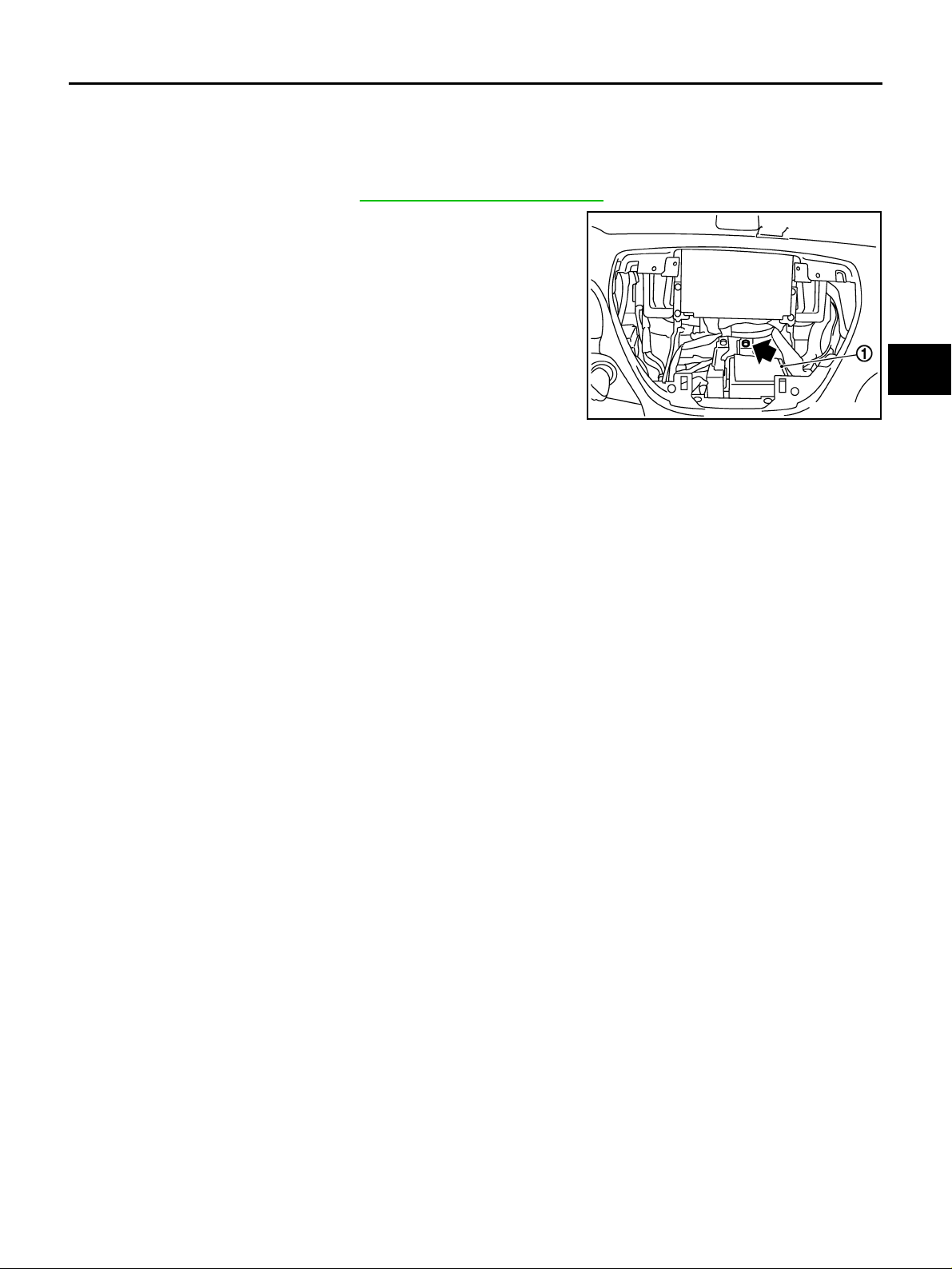
CONTROL UNIT
CONTROL UNIT PFP:40720
Removal and Installation NES000D8
REMOVAL
1. Turn the ignition switch OFF and disconnect the battery cable from the negative terminal.
2. Remove the cluster lid C. Refer to IP-1 0, "
3. Remove the low tire pressure warning control unit bolt.
4. Disconnect the low tire pressure warning control unit harness
connector and antenna harness connector.
5. Remove the low tire pressure warning control unit (1).
INSTALLATION
Note the following, and installation is the reverse order of removal.
● When installing the low tire pressure warning control unit, tighten bolt to the specified torque.
Low tire pressure warning control unit bolt : 3.4 N·m (0.35 kg-m, 30 in-lb)
Removal and Installation" .
SEIA0753E
A
B
C
D
WT
F
G
H
K
M
I
J
L
Revision: 2005 November 2006 Q45
WT-49
Page 50
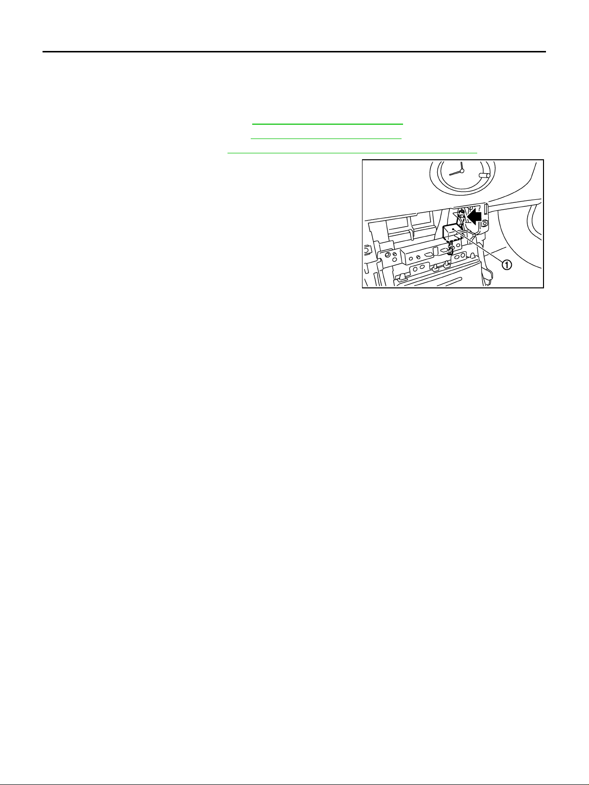
COMBINATION FLASHER UNIT
COMBINATION FLASHER UNIT PFP:25730 Removal and Installation NES000HJ
REMOVAL
1. Turn the ignition swi tch OFF and disconnect the battery cable from the negative terminal.
2. Remove cluster lid center lower. Refer to IP-10, "
3. Remove console box assembly. Refer to IP-10, "
4. Remove CD auto changer. Refer to AV-52, "
5. Remove combination flasher unit bolt.
6. Remove combination flasher unit (1).
7. Disconnect combination flasher unit harness connector.
INSTALLATION
Note the following, and installation is the reverse order of remov a l.
● When installing the low tire pressure warning control unit, tighten bolt to the specified torque.
Removal and Installation" .
Removal and Installation" .
Removal and Installation of CD Auto Changer" .
SEIA0784E
Combination flasher unit bolt : 3.4 N·m (0.35 kg-m, 30 in-lb)
Revision: 2005 November 2006 Q45
WT-50
Page 51
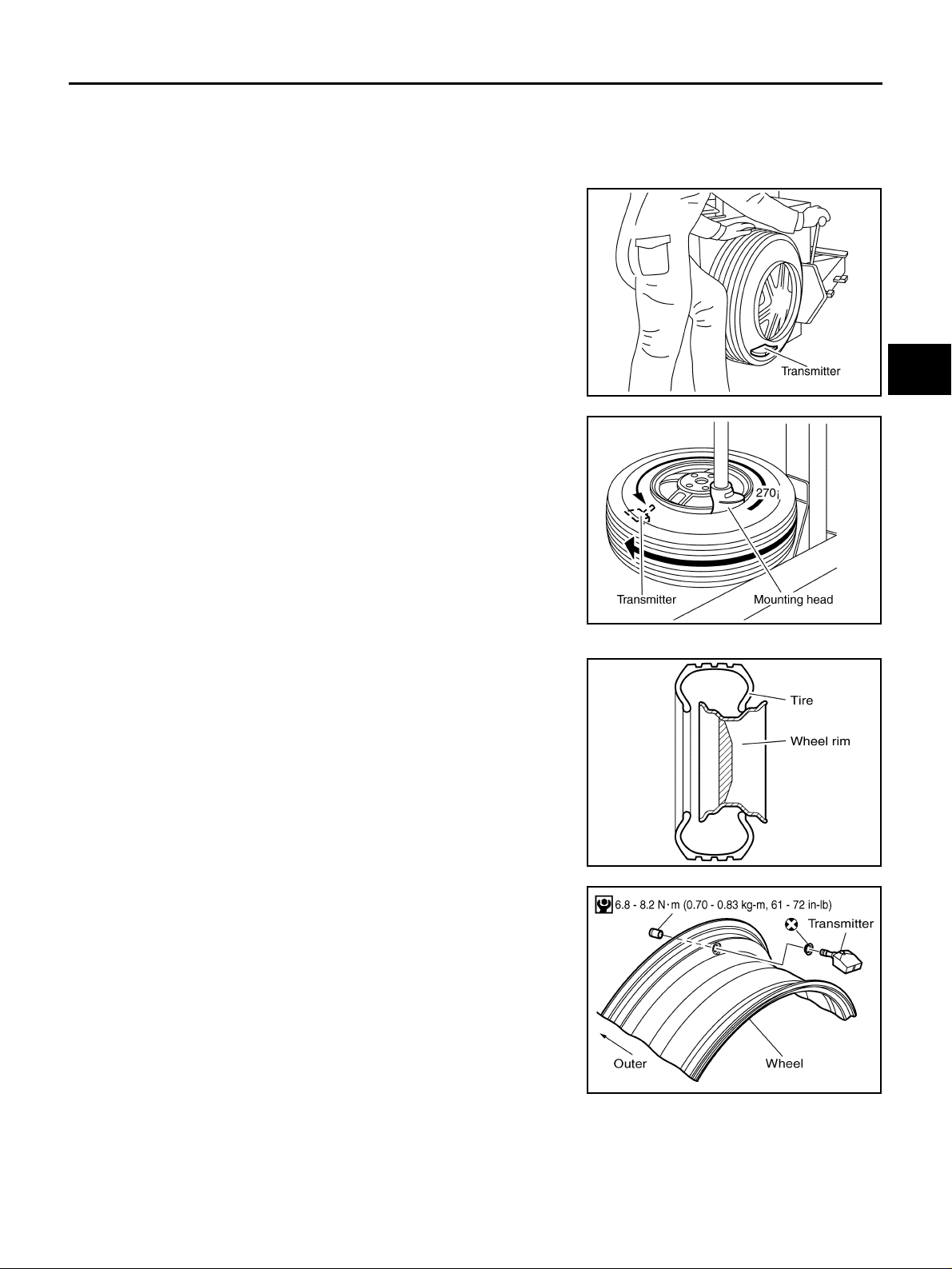
TRANSMITTER
TRANSMITTER PFP:40700
Removal and Installation NES000D9
REMOVAL
1. Deflate tire. Unscrew transmitter retaining nut and allow transmitter to fall into tire.
2. Gently bounce tire so that transmitter falls to bottom of tire.
Place on tire changing machine and break both tire beads
ensuring that the transmitter remains at the bottom of the tire.
SEIA0047E
A
B
C
D
WT
3. Turn tire so that valve hole is at bottom and bounce so that
transmitter is near valve hole. Carefully lift tire onto turntable and
position valve hole (and transmitter) 270 degree from mounting/
dismounting head.
4. Lubric ate ti re wel l and re move first si de of th e tire. Re ach in side
the tire and remove the transmitter. Remove second side of tire.
INSTALLATION
1. Put first side of tire onto rim.
2. Mount transmitter on rim and tighten nut.
CAUTION:
Speed for tightening nut should be less than 40 rpm.
SEIA0048E
SEIA0049E
F
G
H
I
J
K
L
M
SEIA0203E
Revision: 2005 November 2006 Q45
WT-51
Page 52
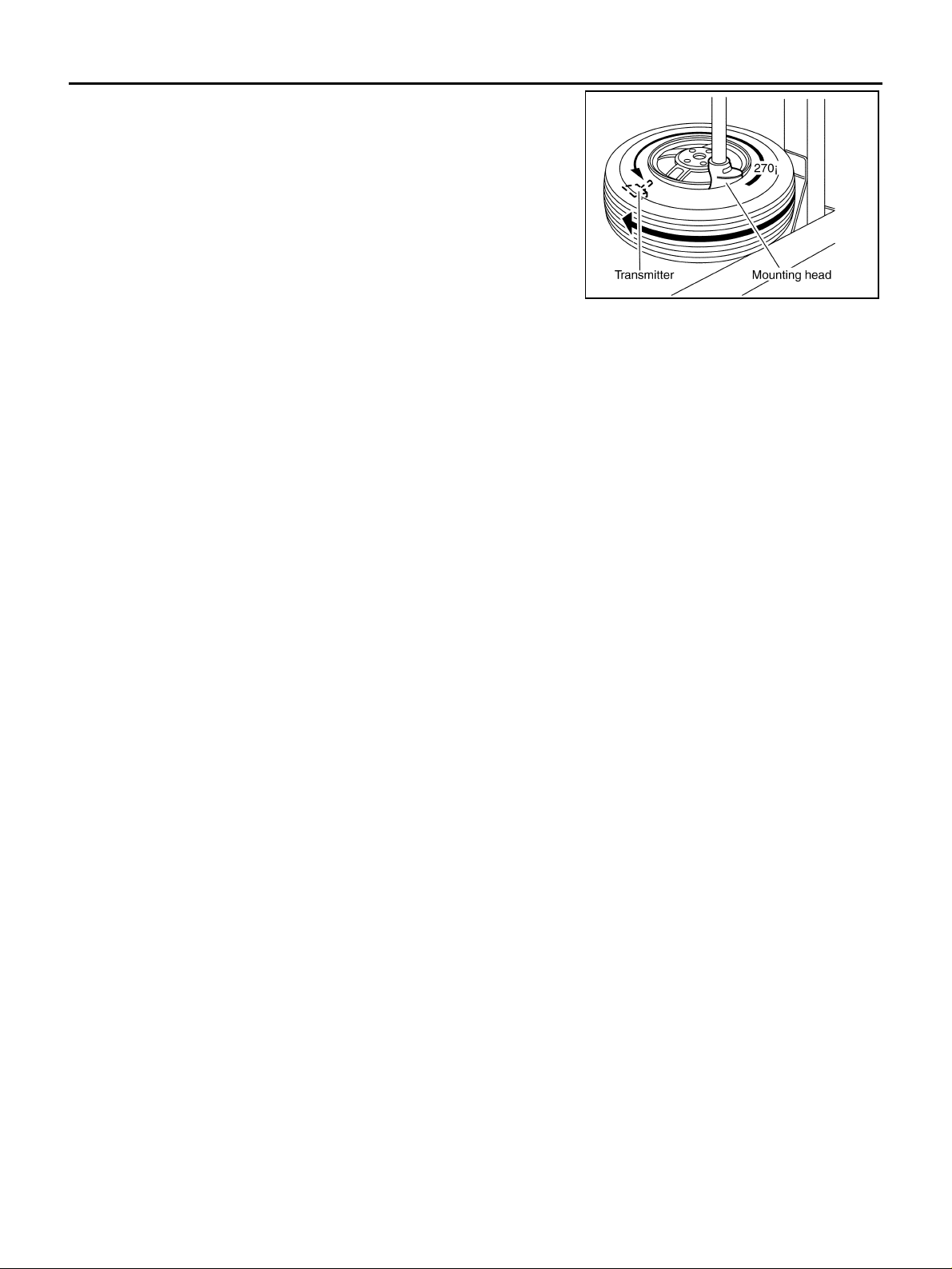
TRANSMITTER
3. Place wheel o n t u rntable of ti re m ac hi ne . En su re t h at tr an smi tte r
is 270 degree from mounting head when second side of tire is
fitted.
CAUTION:
Never touch the transmitter at mounting head.
4. Lubricate tire well and fit second side of tire as normal. Ensure
that tire does not rotate relative to rim.
5. Inflate tire and fit to appropriate wheel position.
SEIA0048E
Revision: 2005 November 2006 Q45
WT-52
Page 53
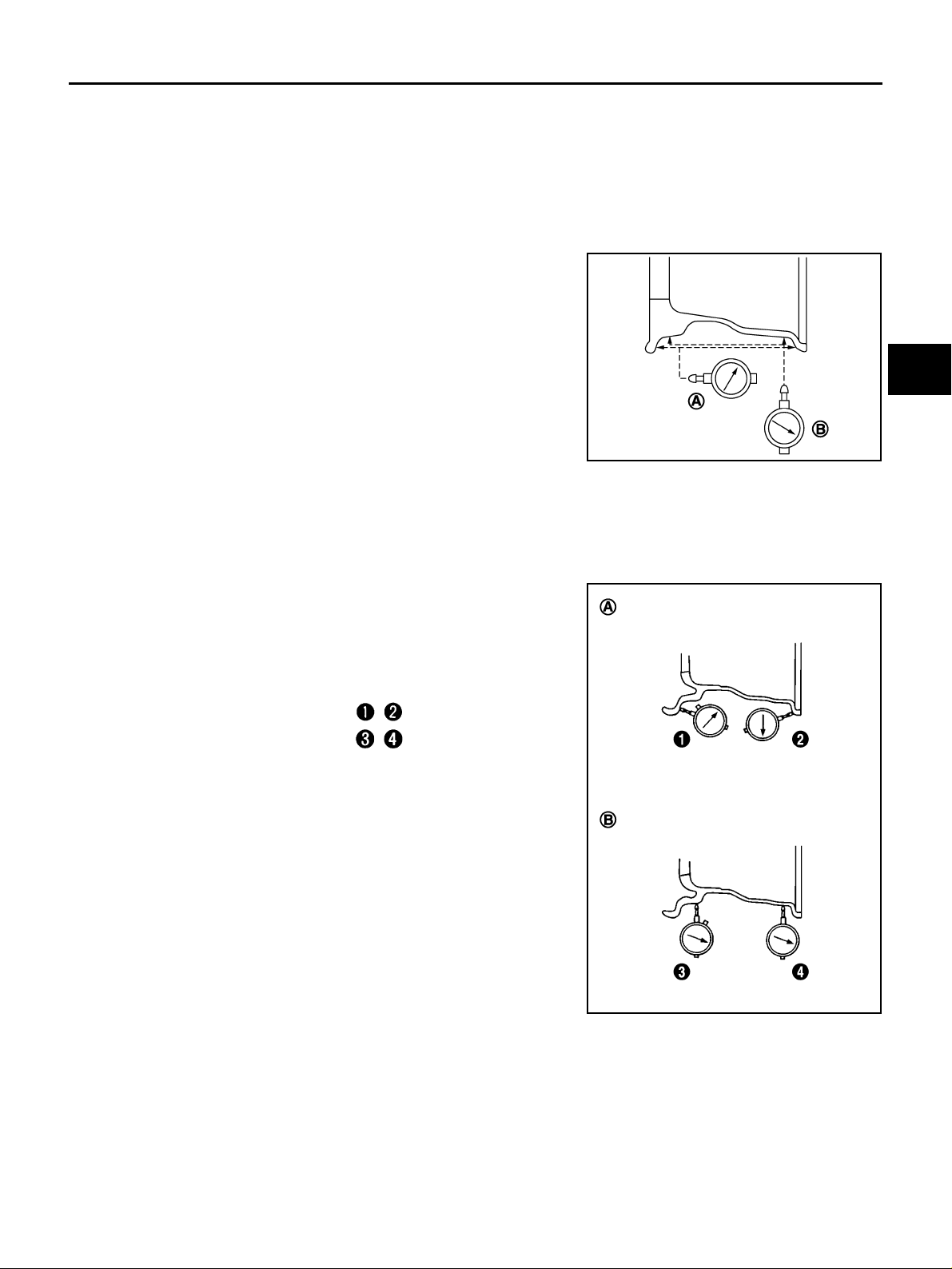
ROAD WHEEL
ROAD WHEEL PFP:40300
Inspection NES00071
ALUMINUM WHEEL
1. Check tires for wear and improper inflation.
2. Check wheels for deformation, cracks and other damage. If deformed, remove wheel and check wheel
runout.
a. Remove tire from aluminum wheel and mount on a tire balance machine.
b. Set dial indicator as shown in the figure.
Lateral runout limit (A) : 0.3 mm (0.012 in)
Radial runout limit (B) : 0.3 mm (0.012 in)
c. If the total runout value exceeds the limit, replace aluminum
wheel.
SEIA0737E
STEEL WHEEL (FOR EMERGENCY USE)
1. Check tires for wear and improper inflation.
2. Check wheels for deformation, cracks and other damage. If deformed, remove wheel and check wheel
runout.
a. Remove tire from steel wheel and mount wheel on a tir e balance machine.
b. Set two dial ind ic ators as shown in the figure.
c. Set each dial indicator to “0”.
d. Rotate whe el and check dial indicato rs at several poi nts around
the circumference of the wheel.
e. Calculate runout at each point as shown below.
Lateral runout limit (A)
Radial runout limit (B)
f. Select maximum pos itive runout va lue and the max imum nega-
tive value. Add the two valu es to determin e total runout.
CAUTION:
In case a positive or negative value is not availa ble , us e the
maximum value (negative or positive) for total runout.
: ( + )/2
: ( + )/2
A
B
C
D
WT
F
G
H
I
J
K
L
Lateral runout limit (A) : 1.5 mm (0.059 in)
Radial runout limit (B) : 1.5 mm (0.059 in)
g. If the total runout value exceeds the limit, replace steel wheel.
SEIA0738E
Revision: 2005 November 2006 Q45
WT-53
M
Page 54
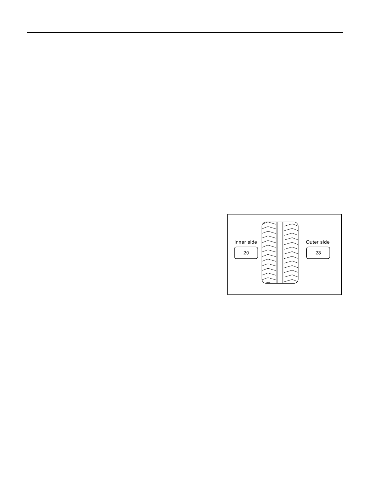
ROAD WHEEL TIRE ASSEMBLY
ROAD WHEEL TIRE ASSEMBLY PFP:40300 Balancing Wheels (Bonding Weight Type) NES00072
REMOVAL
1. Remove inner and outer balance weights from the road wheel.
CAUTION:
Be careful not to scratch the road wheel during removal.
2. Using releasing agent, remove double-faced adhesive tape from the road wheel.
CAUTION:
● Be careful not to scratch the road wheel during removal.
● After removing double-face d adhesive tape, wipe clean trace s of releasing agent from the road
wheel.
WHEEL BALANCE ADJUSTMENT
● If a tire balance mac hine has adhesion balance weigh t mode settings a nd drive-in weig ht mode setting,
select and adjust a drive-in weight mode suitable for road wheels.
1. Set road whee l on wheel balancer using the center hole as a guide. Start the tire ba lance machine.
2. When inner and outer unbalance values are shown on the wheel balancer indicator, multiply outer unbalance value by 5/3 to d eterm ine ba lanc e we ight th at sho uld be used. Sel ect th e ou ter balan ce w eight with
a value closest to the calculated value above and install it to the designated outer position of, or at the
designated angle in relation to the road wheel.
CAUTION:
● Never install the inner balance weight before installing the outer balance weight.
● Before installing the balan ce we ight, b e su re to clean the
mating surfac e of the road wheel.
a. Indicated unbalance value × 5/3 = balance weight to be installed
Calculation example:
23 g (0.81 oz) × 5/3 = 38.3 3 g ( 1.3 5 oz ) = 40 g (1 .41 oz ) bal anc e
weight (closer to calculated balance weight value)
NOTE:
Note that balance weight value must be closer to the calculated
balance weight value.
Example:
37.4 = 35 g (1.23 oz)
37.5 = 40 g (1.41 oz)
SMA054D
Revision: 2005 November 2006 Q45
WT-54
Page 55
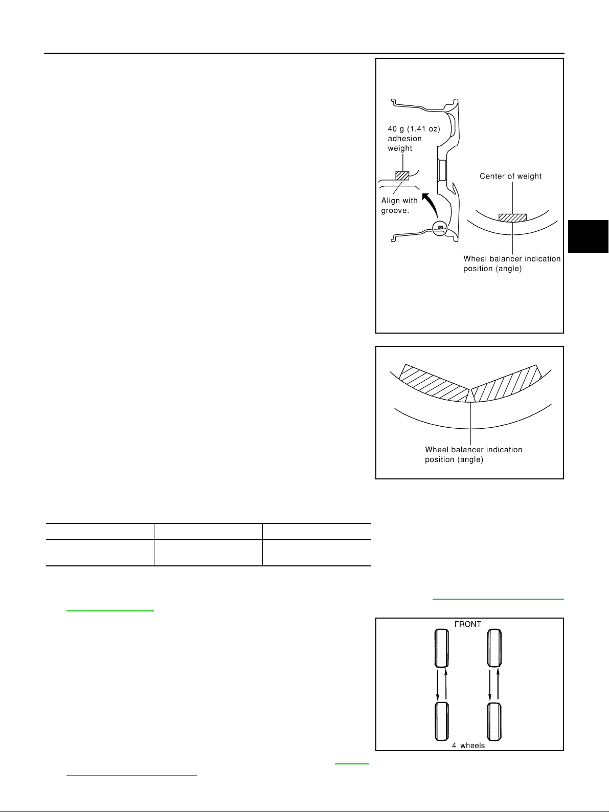
ROAD WHEEL TIRE ASSEMBLY
b. Install bala nce weight in the position shown in the figure.
c. When installing balance weight to road wheels, set it into the
grooved area on the i nner wa ll of the ro ad whe el as shown in th e
figure so tha t the ba lanc e weig ht ce nte r is ali gned with the wh eel
balancer indi cation position (angle).
CAUTION:
● Always use genuine Nissan adhesion balance weights.
● Balance weights are non-reusable; always replace with
new ones.
● Never install more th an three sheets of balance weight.
A
B
C
D
WT
F
SEIA0271E
d. If calculated balance weight value exceeds 50 g (1.76 oz), install
two balance w eight sheets in line with each o ther (as shown in
the figure).
CAUTION:
Never install one balance weight sheet on top of another.
3. Start wheel balancer again.
4. Install dri ve-in bala nce w eight on in ner side o f road w hee l in the
wheel balancer indication position (angle).
CAUTION:
Never install more than two balance weights.
SMA056D
5. Start wheel balancer. Make sure that inner and outer residual
unbalance values are 5 g (0.17 oz) each or below.
6. If either residual unbalance value exceeds 5 g (0.17 oz), repeat installation procedures.
Wheel balance Dynamic (At rim flange) Static
Maximum allowable
unbalance
5 g (0.17 oz) (one side) 10 g (0.35 oz)
Tire Ro tation NES00073
1. Follow the maintenance schedule for tire rotation service intervals. Refer to MA-6, "Introduction of Peri-
odic Maintenance" .
2. Do not include the spare tire when rotating the tires.
3. When installing the wheel, tighten wheel nuts to the specified
torque.
Wheel nuts : 108 N·m (11 kg-m, 80 ft-lb)
G
H
I
J
K
L
M
CAUTION:
● When installing wheels, tigh ten them diagonally by di vid-
ing the work two to three times in order to prevent the
wheels from developing any distortion.
● Be careful not to tighten wheel nut at torque exceeding
the criteria for preventing strain of disc rotor.
SMA829C
4. Perform th e ID registration, after tire rotation. Refer to WT-24,
"ID Registration Procedure" .
Revision: 2005 November 2006 Q45
WT-55
Page 56
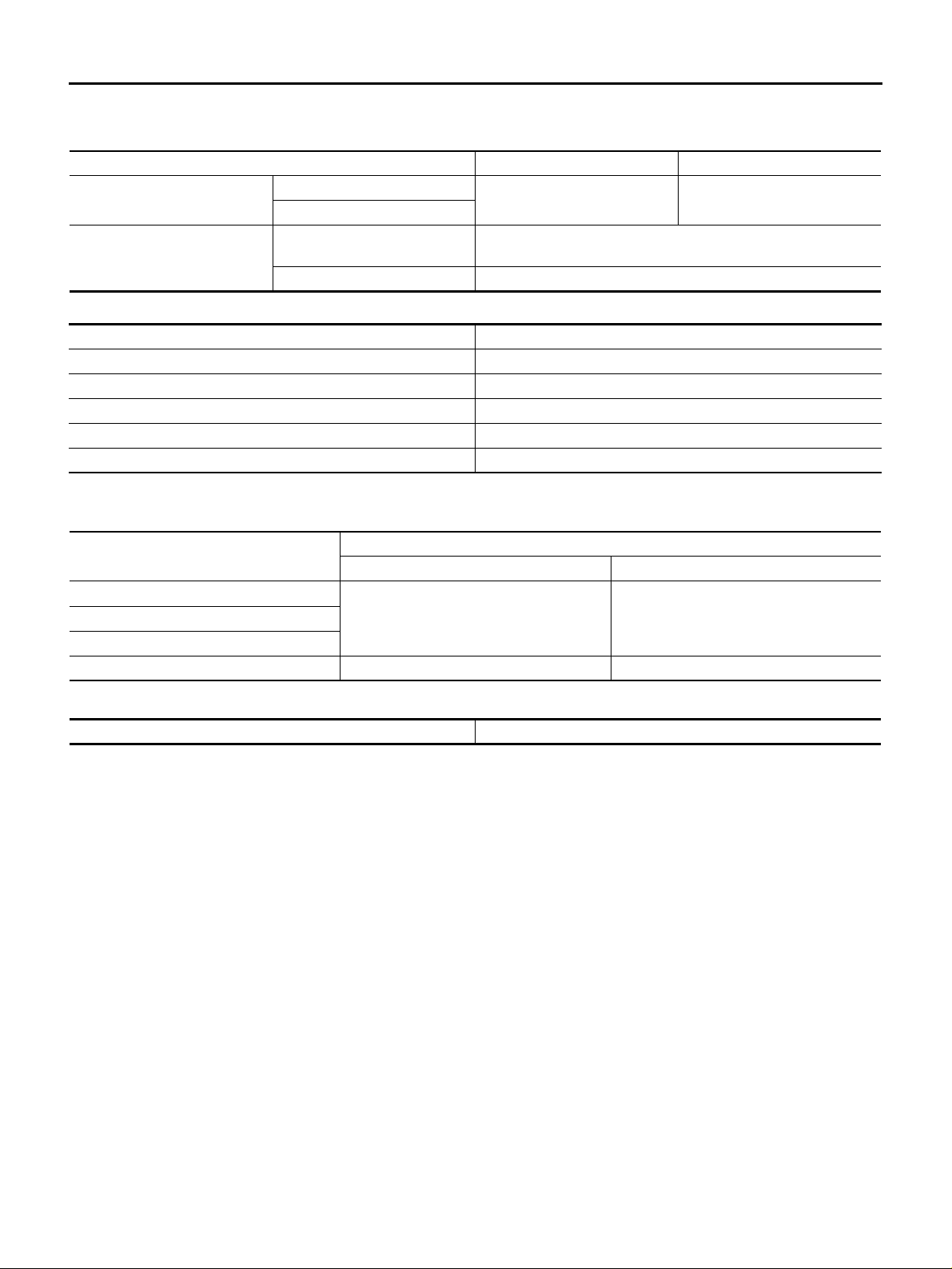
SERVICE DATA AND SPECIFICATIONS (SDS)
SERVICE DATA AND SPECIFICATIONS (SDS) PFP:00030 Road Wheel NES000DH
Kind of wheel Aluminum Steel (emergency use)
Maximum radial runout limit
Maximum allowable unbalance
Lateral runout limit
Radial runout limit
Dynamic
(On the ear part)
Static (On the ear part) 10 g (0.35 oz) or less
Wheel size Offset
17 × 7-1/2 JJ 35 (1.38)
18 × 8 JJ 40 (1.57)
18 × 7-1/2 JJ 35 (1.38)
19 × 8-1/2 JJ 40 (1.57)
16 × 4T 30 (1.18)
0.3 mm (0.012 in) 1.5 mm (0.059 in)
5 g (0.17 oz) (per side) or less
Unit: mm (in)
Tire NES000DI
Unit: kPa (kg/cm2 , psi)
Tire size
P225/55R17 95V
245/40R19 94W
T145/90D16 420 (4.2, 60) 420 (4.2, 60)
Front Rear
230 (2.3, 33) 230 (2.3, 33)P245/45R18 96V
Air pressure
Tightening Torque NES000DJ
Wheel nut 108 N·m (11 kg-m, 80 ft-lb)
Revision: 2005 November 2006 Q45
WT-56
 Loading...