

Page 1
w
24-bit 192kHz Stereo DAC
DESCRIPTION
The WM8726 is a high performance stereo DAC designed
for audio applications such as DVD, home theatre systems,
and digital TV. The WM8726 supports data input word
lengths from 16 to 24-bits and sampling rates up to 192kHz.
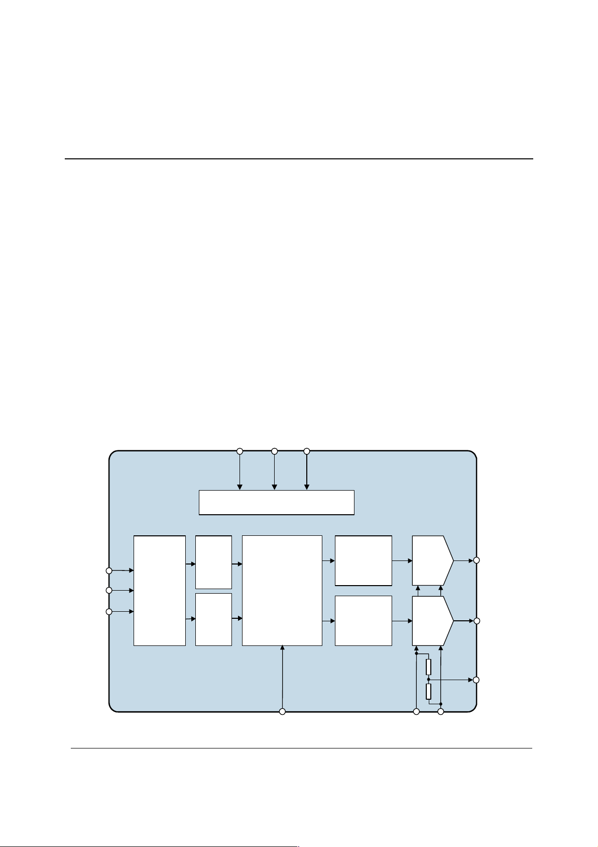
The WM8726 consists of a serial interface port, digital
interpolation filters, multi-bit sigma delta modulators and
stereo DAC in a 14-pin SOIC package.
The WM8726 has a hardware control interface for selection
of audio data interface format, mute and de-emphasis. The
WM8726 supports I
The WM8726 is an ideal device to interface to AC-3,
DTS, and MPEG audio decoders for surround sound
applications, or for use in DVD players, including supporting
the implementation of 2 channels at 192kHz for high-end
DVD-Audio applications.
2
S, right Justified or DSP interfaces.
WM8726
FEATURES
• Stereo DAC
• Audio Performance
- 100dB SNR (‘A’ weighted @ 48kHz)
- -88dB THD
• DAC Sampling Frequency: 8kHz – 192kHz
• Pin Selectable Audio Data Interface Format
• 2.7V - 5.5V Supply Operation
• 14-pin SOIC Package
• Pin Compatible with WM8725
APPLICATIONS
• DVD Players
• Home Theatre Systems
• Digital TV
• Digital Set Top Boxes
2
S, 16-bit Right Justified or DSP
- I
BLOCK DIAGRAM
BCKIN
LRCIN
DIN
AUDIO
INTERFACE
MUTE
MUTE
CONTROL
INTERFACE
DIGITAL
FILTERS
DEEMPHMUTEFORMAT
W
WM8726
SIGMA
DELTA
MODULATOR
SIGMA
DELTA
MODULATOR
RIGHT
DAC
LEFT
DAC
VOUTR
VOUTL
CAP
WOLFSON MICROELECTRONICS plc
www.wolfsonmicro.com
MCLK
GNDVDD
Production Data, March 2004, Rev 4.0
Copyright 2004 Wolfson Microelectronics plc
Page 2

WM8726 Production Data
TABLE OF CONTENTS
DESCRIPTION ............................................................................................................1
FEATURES..................................................................................................................1
APPLICATIONS ..........................................................................................................1
BLOCK DIAGRAM ......................................................................................................1
TABLE OF CONTENTS ..............................................................................................2
PIN CONFIGURATION................................................................................................3
ORDERING INFORMATION .......................................................................................3
PIN DESCRIPTION .....................................................................................................4
ABSOLUTE MAXIMUM RATINGS..............................................................................5
DC ELECTRICAL CHARACTERISTICS .....................................................................6
ELECTRICAL CHARACTERISTICS ...........................................................................6
TERMINOLOGY................................................................................................................. 7
MASTER CLOCK TIMING.................................................................................................. 8
DIGITAL AUDIO INTERFACE ............................................................................................ 8
DEVICE DESCRIPTION ..............................................................................................9
GENERAL INTRODUCTION .............................................................................................. 9
DAC CIRCUIT DESCRIPTION ........................................................................................... 9
CLOCKING SCHEMES .....................................................................................................10
DIGITAL AUDIO INTERFACE ...........................................................................................10
AUDIO DATA SAMPLING RATES.....................................................................................12
HARDWARE CONTROL MODES .....................................................................................13
DIGITAL FILTER CHARACTERISTICS.............................................................................15
DAC FILTER RESPONSES...............................................................................................15
DIGITAL DE-EMPHASIS CHARACTERISTICS........................................................16
APPLICATIONS INFORMATION ..............................................................................17
RECOMMENDED EXTERNAL COMPONENTS................................................................17
RECOMMENDED EXTERNAL COMPONENTS VALUES.................................................17
RECOMMENDED ANALOGUE LOW PASS FILTER ........................................................18
PCB LAYOUT RECOMMENDATIONS ..............................................................................18
PACKAGE DRAWING...............................................................................................19
IMPORTANT NOTICE ...............................................................................................20
ADDRESS: ........................................................................................................................20
w
PD Rev 4.0 March 2004
2
Page 3
WM8726 Production Data
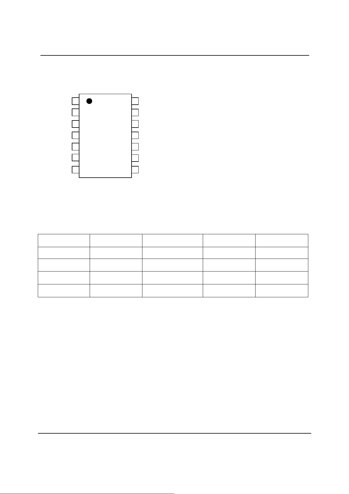
PIN CONFIGURATION
9
8
MCLK
FORMAT
DEEMPH
NC
MUTE
VOUTL
VDD
LRCIN
DIN
BCKIN
NC
CAP
VOUTR
GND
1
2
3
WM8726
4
5
6
7
14
13
12
11
10
ORDERING INFORMATION
DEVICE TEMP. RANGE PACKAGE
WM8726ED -25 to +85oC 14-pin SOIC MSL1
WM8726ED/R -25 to +85oC
WM8726GED -25 to +85oC
WM8726GED/R -25 to +85oC
Notes:
Reel quantity = 3,000
14-pin SOIC
(tape and reel)
14-pin SOIC
(lead free)
14-pin SOIC
(lead free, tape and reel)
SENSITIVITY LEVEL
MOISTURE
MSL1
MSL1
MSL1
PEAK SOLDERING
TEMP.
o
240
C
o
240
C
o
260
C
o
260
C
w
PD Rev 4.0 March 2004
3
Page 4

WM8726 Production Data
PIN DESCRIPTION
PIN NAME TYPE DESCRIPTION
1
2
3
4
5
6
7
8
9
10
11
12
13
14
Note:
1. Digital input pins have Schmitt trigger input buffers.
LRCIN Digital input Sample rate clock input
DIN Digital input Serial audio data input
BCKIN Digital input Bit clock input
NC No connect No internal connection
CAP Analogue output Analogue internal reference
VOUTR Analogue output Right channel DAC output
GND Supply Negative supply
VDD Supply Positive supply
VOUTL Analogue output Left channel DAC output
MUTE Digital input Soft mute control, Internal pull down
High Impedance = Automute
High = Mute ON
Low = Mute OFF
NC No connect No internal connection
DEEMPH Digital input De-emphasis select, Internal pull up
High = de-emphasis ON
Low = de-emphasis OFF
FORMAT Digital input Data input format select, Internal pull up
Low = 16-bit right justified or DSP ‘late’
High = 16-24-bit I
MCLK Digital input Master clock input
2
S or DSP ‘early’
w
PD Rev 4.0 March 2004
4
Page 5
WM8726 Production Data
ABSOLUTE MAXIMUM RATINGS
Absolute Maximum Ratings are stress ratings only. Permanent damage to the device may be caused by continuously operating at
or beyond these limits. Device functional operating limits and guaranteed performance specifications are given under Electrical
Characteristics at the test conditions specified.
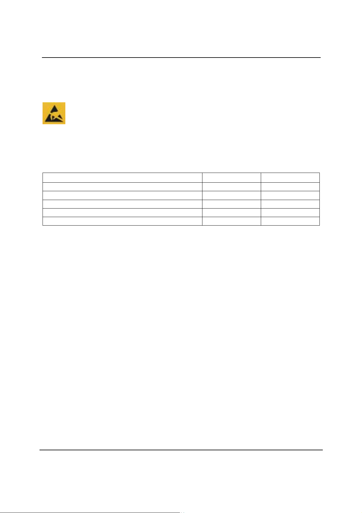
ESD Sensitive Device. This device is manufactured on a CMOS process. It is therefore generically susceptible
to damage from excessive static voltages. Proper ESD precautions must be taken during handling and storage
of this device.
Wolfson tests its package types according to IPC/JEDEC J-STD-020B for Moisture Sensitivity to determine acceptable storage
conditions prior to surface mount assembly. These levels are:
MSL1 = unlimited floor life at <30°C / 85% Relative Humidity. Not normally stored in moisture barrier bag.
MSL2 = out of bag storage for 1 year at <30°C / 60% Relative Humidity. Supplied in moisture barrier bag.
MSL3 = out of bag storage for 168 hours at <30°C / 60% Relative Humidity. Supplied in moisture barrier bag.
The Moisture Sensitivity Level for each package type is specified in Ordering Information.
CONDITION
Supply voltage
Voltage range digital inputs
Master Clock Frequency
Operating temperature range, TA
Storage temperature after soldering -65°C +150°C
MIN MAX
-0.3V +7V
GND -0.3V VDD +0.3V
50MHz
-25°C +85°C
w
PD Rev 4.0 March 2004
5
Page 6
WM8726 Production Data
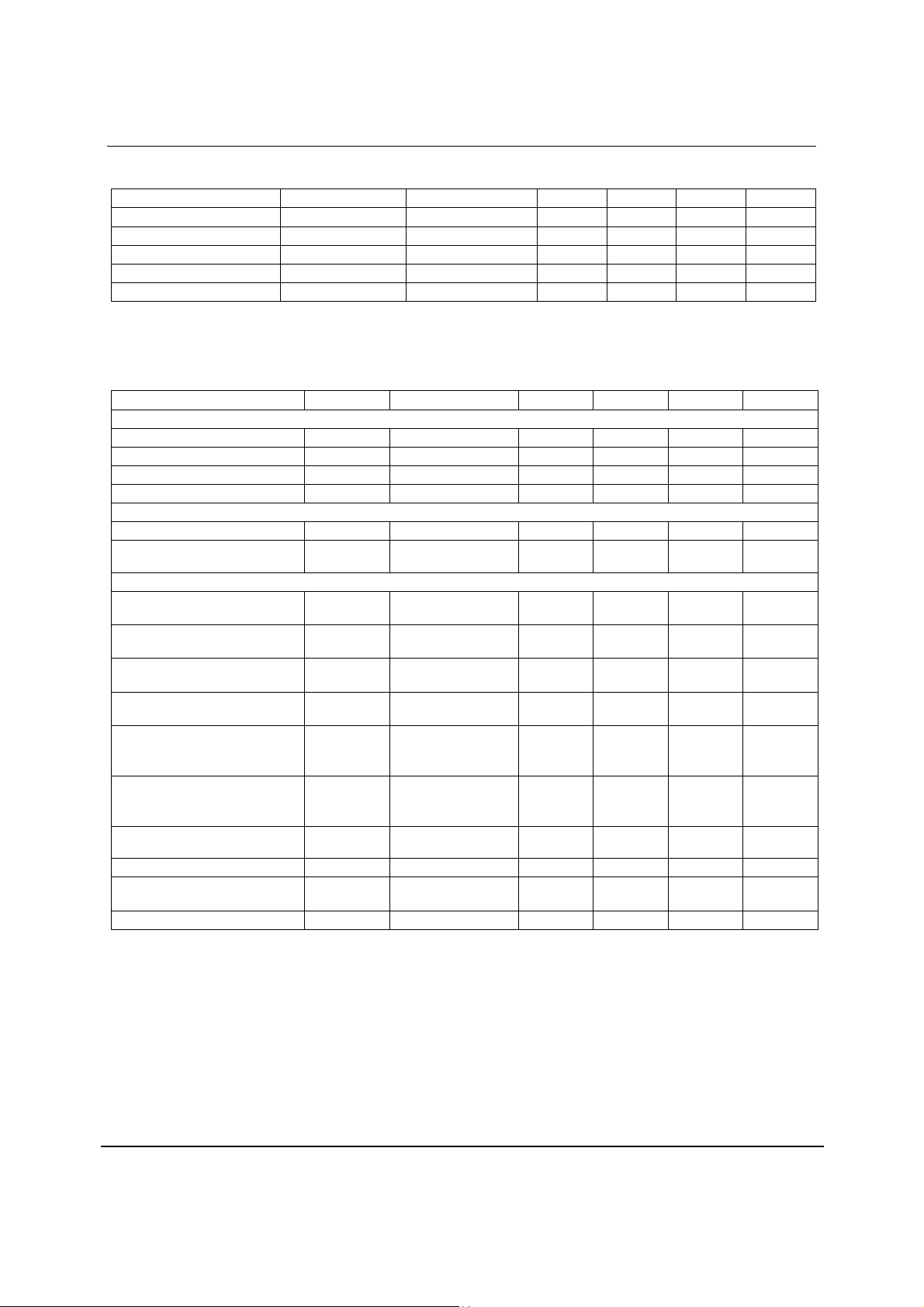
DC ELECTRICAL CHARACTERISTICS
PARAMETER SYMBOL TEST CONDITIONS MIN TYP MAX UNIT
Supply range
Ground
Supply current
Supply current
Power down current (note 4)
VDD 2.7 5.5 V
GND 0 V
VDD = 5V 27 mA
VDD = 3.3V 23 mA
VDD=3.3V 0.5 mA
ELECTRICAL CHARACTERISTICS
Test Conditions
VDD = 5V, GND = 0V, T
PARAMETER SYMBOL TEST CONDITIONS MIN TYP MAX UNIT
Digital Logic Levels (TTL Levels)
Input LOW level VIL
Input HIGH level VIH
Output LOW VOL
Output HIGH VOH
Analogue Reference Levels
Reference voltage (CAP)
Potential divider resistance R
DAC Output (Load = 10kΩΩΩΩ 50pF)
0dBFs Full scale output voltage
SNR (Note 1,2,3)
SNR (Note 1,2,3)
SNR (Note 1,2,3)
SNR (Note 1,2,3)
SNR (Note 1,2,3)
SNR (Note 1,2,3)
THD (Note 3)
Dynamic Range (Note 2)
DAC channel separation
= +25oC, fs = 48kHz, MCLK = 256fs unless otherwise stated.
A
0.8 V
2.0 V
I
= 2mA GND + 0.3V V
OL
I
= 2mA VDD - 0.3V V
OH
VDD/2 V
CAP
Non ‘A’ weighted @ fs
1kHz, 0dBFs -88 dB
1kHz, THD+N @
93 dB
VDD to CAP and CAP
to GND
At DAC outputs 1.1 x
A-weighted,
@ fs = 48kHz
A-weighted
@ fs = 96kHz
A-weighted
@ fs = 192kHz
A-weighted,
@ fs = 48kHz
VDD = 3.3V
A-weighted
@ fs = 96kHz
VDD = 3.3V
= 48kHz
-60dBFs
50k Ω
90 100 dB
97 dB
97 dB
95 dB
95 dB
98 dB
90 100 dB
VDD/5
V
rms
w
PD Rev 4.0 March 2004
6
Page 7
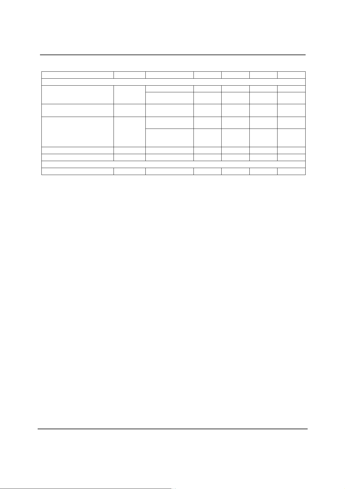
WM8726 Production Data
Test Conditions
VDD = 5V, GND = 0V, T
PARAMETER SYMBOL TEST CONDITIONS MIN TYP MAX UNIT
Analogue Output Levels
Output level
Gain mismatch
channel-to-channel
Minimum resistance load
Maximum capacitance load
Output d.c. level
Power On Reset (POR)
POR threshold
Notes:
1. Ratio of output level with 1kHz full scale input, to the output level with all zeros into the digital input, measured ‘A’ weighted
over a 20Hz to 20kHz bandwidth.
2. All performance measurements done with 20kHz low pass filter, and where noted an A-weight filter. Failure to use such a
filter will result in higher THD+N and lower SNR and Dynamic Range readings than are found in the Electrical
Characteristics. The low pass filter removes out of band noise; although it is not audible it may affect dynamic specification
values.
3. CAP pin decoupled with 10uF and 0.1uF capacitors (smaller values may result in reduced performance).
4. Power down occurs 1.5µs after MCLK is stopped.
= +25oC, fs = 48kHz, MCLK = 256fs unless otherwise stated.
A
±1 %FSR
5V or 3.3V 100 pF
VDD/2 V
1.8 V
Load = 10kΩ, 0dBFS 1.1 V
Load = 10kΩ, 0dBFS,
(VDD = 3.3V)
To midrail or a.c.
coupled
To midrail or a.c.
coupled
(VDD = 3.3V)
0.72 V
1 kΩ
1 kΩ
RMS
RMS
TERMINOLOGY
1. Signal-to-noise ratio (dB) - SNR is a measure of the difference in level between the full scale output and the output with no
signal applied. (No Auto-zero or Automute function is employed in achieving these results).
2. Dynamic range (dB) - DNR is a measure of the difference between the highest and lowest portions of a signal. Normally a
THD+N measurement at 60dB below full scale. The measured signal is then corrected by adding the 60dB to it. (e.g.
THD+N @ -60dB= -32dB, DR= 92dB).
3. THD+N (dB) - THD+N is a ratio, of the rms values, of (Noise + Distortion)/Signal.
4. Stop band attenuation (dB) - Is the degree to which the frequency spectrum is attenuated (outside audio band).
5. Channel Separation (dB) - Also known as Cross-Talk. This is a measure of the amount one channel is isolated from the
other. Normally measured by sending a full scale signal down one channel and measuring the other.
w
PD Rev 4.0 March 2004
7
Page 8
WM8726 Production Data
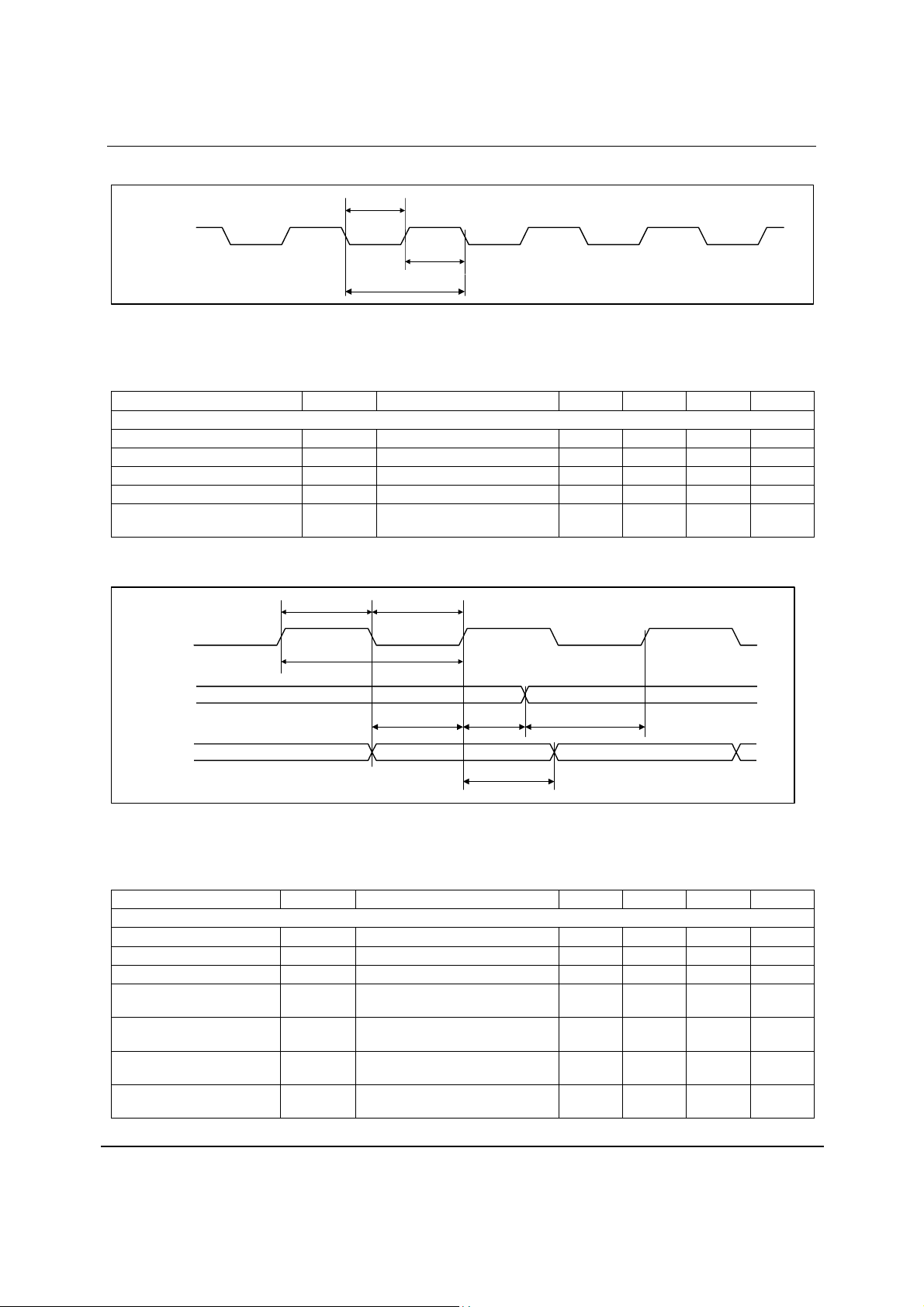
MASTER CLOCK TIMING
t
MCLKL
MCLK
t
MCLKY
t
MCLKH
Figure 1 Master Clock Timing Requirements
Test Conditions
VDD = 5V, GND = 0V, T
= +25oC, fs = 48kHz, MCLK = 256fs unless otherwise stated.
A
PARAMETER SYMBOL TEST CONDITIONS MIN TYP MAX UNIT
System Clock Timing Information
MCLK Master clock pulse width high
MCLK Master clock pulse width low
MCLK Master clock cycle time
MCLK Duty cycle
Time from MCLK stopping to power
down.
t
MCLKH
t
MCLKL
t
MCLKY
8 ns
8 ns
20 ns
40:60 60:40
1.5 12 µs
DIGITAL AUDIO INTERFACE
BCKIN
t
BCH
t
BCY
t
BCL
LRCIN
t
DS
t
LRH
t
LRSU
DIN
t
DH
Figure 2 Digital Audio Data Timing
Test Conditions
VDD = 5V, GND = 0V, T
PARAMETER SYMBOL TEST CONDITIONS MIN TYP MAX UNIT
Audio Data Input Timing Information
BCKIN cycle time
BCKIN pulse width high
BCKIN pulse width low
LRCIN set-up time to
BCKIN rising edge
LRCIN hold time from
BCKIN rising edge
DIN set-up time to BCKIN
rising edge
DIN hold time from BCKIN
rising edge
= +25oC, fs = 48kHz, MCLK = 256fs unless otherwise stated.
A
t
BCY
t
BCH
t
BCL
t
LRSU
t
LRH
t
DS
t
DH
40 ns
16 ns
16 ns
8 ns
8 ns
8 ns
8 ns
w
PD Rev 4.0 March 2004
8
Page 9

WM8726 Production Data
DEVICE DESCRIPTION
GENERAL INTRODUCTION
The WM8726 is a high performance DAC designed for digital consumer audio applications. The
range of features make it ideally suited for use in DVD players, AV receivers and other consumer
audio equipment.
The WM8726 is a complete 2-channel stereo audio digital-to-analogue converter, including digital
interpolation filter, multi-bit sigma delta with dither, and switched capacitor multi-bit stereo DAC
and output smoothing filters. It is fully compatible and an ideal partner for a range of industry
standard microprocessors, controllers and DSPs. A novel multi bit sigma-delta DAC design is
used, utilising a 128x oversampling rate, to optimise signal to noise performance and offer
increased clock jitter tolerance. (In ‘high-rate’ operation, the oversampling ratio is 64x for system
clocks of 128fs or 192fs)
Control of internal functionality of the device is provided by hardware control (pin programmed).
Operation using master clocks of 256fs, 384fs, 512fs or 768fs is provided, selection between
clock rates being automatically controlled. Sample rates (fs) from less than 8kHz to 96kHz are
allowed, provided the appropriate system clock is input. Support is also provided for up to 192kHz
using a master clock of 128fs or 192fs.
The audio data interface supports 16-bit right justified or 16-24-bit I
delayed) interface formats. A DSP interface is also supported, enhancing the interface options for
the user.
A single 2.7-5.5V supply may be used, the output amplitude scaling with absolute supply level.
Low supply voltage operation and low current consumption combined with the low pin count small
package make the WM8726 attractive for many consumer applications.
2
S (Philips left justified, one bit
The device is packaged in a small 14-pin SOIC.
DAC CIRCUIT DESCRIPTION
The W M8726 DAC is designed to allow playback of 24-bit PCM audio or similar data with high
resolution and low noise and distortion. Sample rates up to 192kHz may be used, with much lower
sample rates acceptable provided that the ratio of sample rate (LRCIN) to master clock (MCLK) is
maintained at one of the required rates.
The two DACs on the W M8726 are implemented using sigma-delta oversampled conversion
techniques. These require that the PCM samples are digitally filtered and interpolated to generate
a set of samples at a much higher rate than the up to 192kHz input rate. This sample stream is
then digitally modulated to generate a digital pulse stream that is then converted to analogue
signals in a switched capacitor DAC. The advantage of this technique is that the DAC is linearised
using noise shaping techniques, allowing the 24-bit resolution to be met using non-critical
analogue components. A further advantage is that the high sample rate at the DAC output means
that smoothing filters on the output of the DAC need only have fairly crude characteristics in order
to remove the characteristic steps, or images on the output of the DAC. To ensure that generation
of tones characteristic to sigma-delta convertors is not a problem, dithering is used in the digital
modulator along with a higher order modulator. The multi-bit switched capacitor technique used in
the DAC reduces sensitivity to clock jitter, and dramatically reduces out of band noise compared
to switched current or single bit techniques used in other implementations.
The voltage on the CAP pin is used as the reference for the DACs. Therefore the amplitude of the
signals at the DAC outputs will scale with the amplitude of the voltage at the CAP pin. An external
reference could be used to drive into the CAP pin if desired, with a value typically of about midrail
ideal for optimum performance.
The outputs of the 2 DACs are buffered out of the device by buffer amplifiers. These amplifiers
will source load currents of several mA and sink current up to 1.5mA allowing significant loads to
be driven. The output source is active and the sink is Class A, i.e. fixed value, so greater loads
might be driven if an external ‘pull-down’ resistor is connected at the output.
w
PD Rev 4.0 March 2004
9
Page 10

WM8726 Production Data
Typically an external low pass filter circuit will be used to remove residual out of band noise
characteristic of delta sigma converters. However, the advanced multi-bit DAC used in WM8726
produces far less out of band noise than single bit traditional sigma delta DACs, and so in many
applications this filter may be removed, or replaced with a simple RC pole.
CLOCKING SCHEMES
In a typical digital audio system there is only one central clock source producing a reference clock
to which all audio data processing is synchronised. This clock is often referred to as the audio
system’s Master Clock. The external master clock can be applied directly through the MCLK input
pin with no configuration necessary for sample rate selection.
Note that on the WM8726, MCLK is used to derive clocks for the DAC path. The DAC path
consists of DAC sampling clock, DAC digital filter clock and DAC digital audio interface timing. In
a system where there are a number of possible sources for the reference clock it is recommended
that the clock source with the lowest jitter be used to optimise the performance of the DAC.
The device can be powered down by stopping MCLK. In this state the power consumption is
substantially reduced.
DIGITAL AUDIO INTERFACE
Audio data is applied to the internal DAC filters via the Digital Audio Interface. Three interface
formats are supported:
• Right Justified mode
2
• I
S mode
• DSP mode
All formats send the MSB first. The data format is selected with the FORMAT pin. When
FORMAT is LOW, right justified data format is selected and word lengths up to 16-bits may be
used. When the FORMAT pin is HIGH, I
24-bits may be used. (If a word length shorter than 24-bits is used, the unused bits will be padded
with zeros). If LRCIN is 4 BCKINs or less duration, the DSP compatible format is selected. Early
and Late clock formats are supported, selected by the state of the FORMAT pin.
‘Packed’ mode (i.e. only 32 or 48 clocks per LRCIN period) operation is also supported in both I
(16-24 bits) and right justified formats, (16 bit). If a ‘packed’ format of 16-bit word length is applied
(16 BCKINS per LRCIN half period), the device auto-detects this mode and switches to 16-bit
data length.
2
S format is selected and word length of any value up to
2
I2S MODE
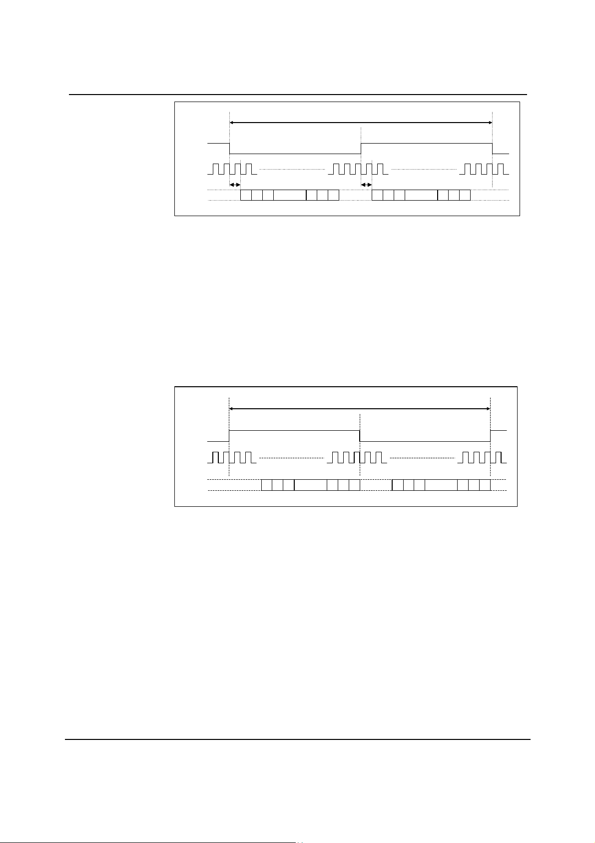
The WM8726 supports word lengths of 16-24 bits in I2S mode.
2
S mode, the digital audio interface receives data on the DIN input. Audio Data is time
In I
multiplexed with LRCIN indicating whether the left or right channel is present. LRCIN is also used
as a timing reference to indicate the beginning or end of the data words.
2
In I
S modes, the minimum number of BCKINs per LRCIN period is 2 times the selected word
length. LRCIN must be high for a minimum of word length BCKINs and low for a minimum of word
length BCKINs. Any mark to space ratio on LRCIN is acceptable provided the above requirements
are met. In I
transition. LRCIN is low during the left samples and high during the right samples.
2
S mode, the MSB is sampled on the second rising edge of BCKIN following a LRCIN
S
w
PD Rev 4.0 March 2004
10
Page 11
WM8726 Production Data
1/fs
LEFT CHANNEL RIGHT CHANNEL
LRCIN
BCKIN
MSB
1 BCKIN
n-2 n-1
n321
LSB
1 BCKIN
DIN
Figure 3 I
MSB
2
S Mode Timing Diagram
n-2 n-1
n321
LSB
RIGHT JUSTIFIED MODE
The WM8726 supports word lengths of 16-bits in right justified mode.
In right justified mode, the digital audio interface receives data on the DIN input. Audio Data is
time multiplexed with LRCIN indicating whether the left or right channel is present. LRCIN is also
used as a timing reference to indicate the beginning or end of the data words.
In right justified mode, the minimum number of BCKINs per LRCIN period is 2 times the selected
word length. LRCIN must be high for a minimum of word length BCKINs and low for a minimum of
word length BCKINs. Any mark to space ratio on LRCIN is acceptable provided the above
requirements are met.
In right justified mode, the LSB is sampled on the rising edge of BCKIN preceding a LRCIN
transition. LRCIN is high during the left samples and low during the right samples.
1/fs
LEFT CHANNEL RIGHT CHANNEL
LRCIN
BCKIN
DIN
321
14 15
16
LSBMSB
321
14 15
16
LSBMSB
Figure 4 Right Justified Mode Timing Diagram
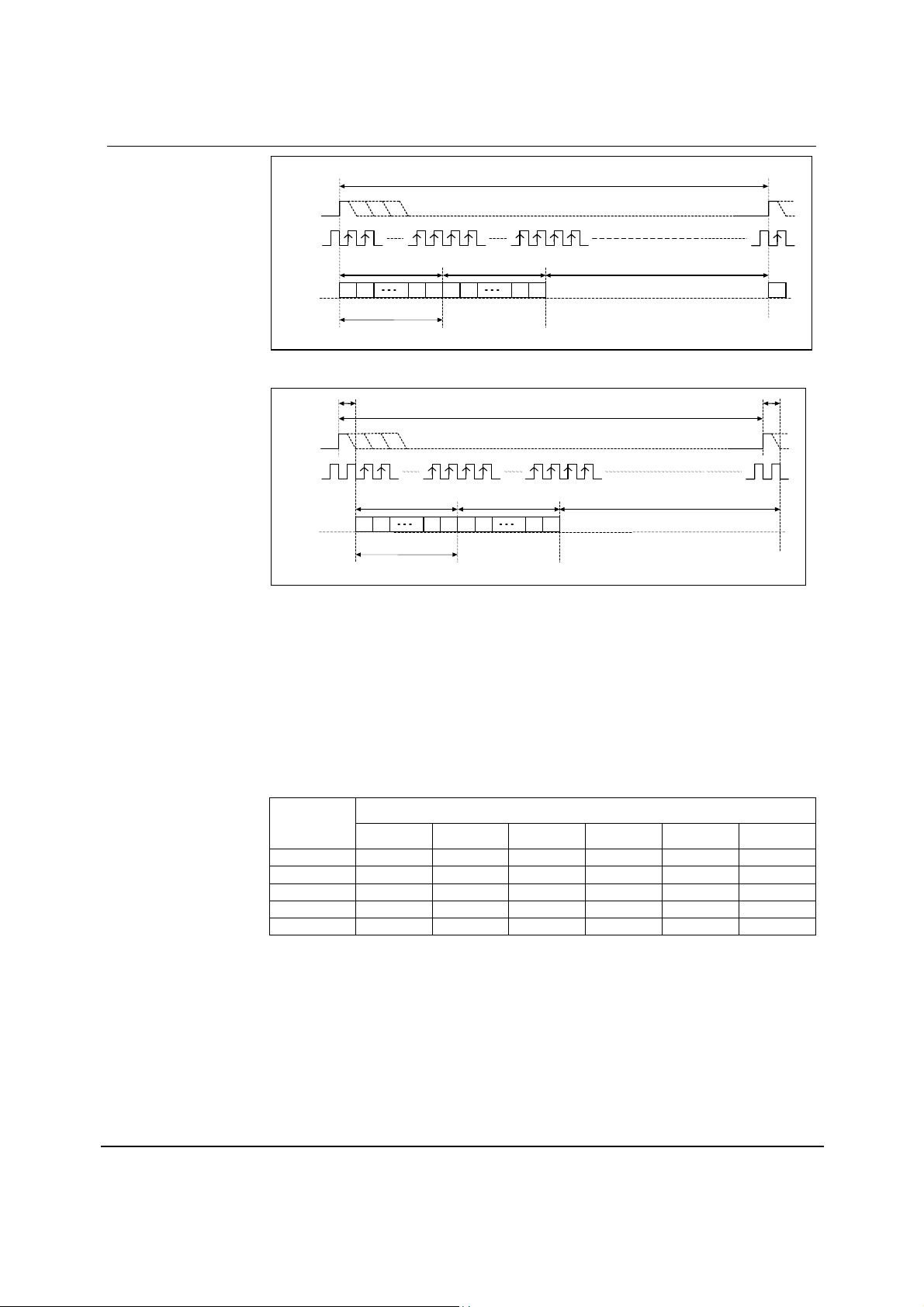
DSP MODE
A DSP compatible, time division multiplexed format is also supported by the WM8726. This
format is of the type where a ‘synch’ pulse is followed by two data words (left and right) of
predetermined word length. (16-bits). The ‘synch’ pulse replaces the normal duration LRCIN, and
DSP mode is auto-detected by the shorter than normal duration of the LRCIN. If LRCIN is of 4
BCKIN or less duration, the DSP compatible format is selected. Early and Late clock formats are
supported, selected by the state of the FORMAT pin.
w
PD Rev 4.0 March 2004
11
Page 12
WM8726 Production Data
1/fs
LRCIN
BCKIN
Max 4 BCK IN's
DIN
Input Word Length (16 bits)
Figure 5 DSP ‘Late’ Mode Timing
max 4 BCKIN 's
LRCIN
BCKIN
DIN
Figure 6 DSP ‘Early’ Mode Timing
AUDIO DATA SAMPLING RATES
The master clock for WM8726 supports audio sampling rates from 128fs to 768fs, where fs is the
audio sampling frequency (LRCIN) typically 32kHz, 44.1kHz, 48kHz, 96kHz or 192kHz. The
master clock is used to operate the digital filters and the noise shaping circuits.
LEFT CHANNEL
2 1
1 BCKIN
Input Word Length (16 bits)
15
LSB MSB
LEFT CHANNEL
2 1
RIGHT CHANNEL NO VALID DATA
2 1
16
16
15
LSB MSB
15
RIGHT CHANNEL
2 1
15
16
1/fs
16
1
1 BCKIN
NO VALID DATA
w
The WM8726 has a master clock detection circuit that automatically determines the relation
between the master clock frequency and the sampling rate (to within +/- 8 master clocks). If there
is a greater than 8 clocks error, the interface shuts down the DAC and mutes the output. The
master clock should be synchronised with LRCIN, although the W M8726 is tolerant of phase
differences or jitter on this clock.
SAMPLING
RATE
(LRCIN)
128fs 192fs 256fs 384fs 512fs 768fs
MASTER CLOCK FREQUENCY (MHZ) (MCLK)
32kHz 4.096 6.144 8.192 12.288 16.384 24.576
44.1kHz 5.6448 8.467 11.2896 16.9344 22.5792 33.8688
48kHz 6.144 9.216 12.288 18.432 24.576 36.864
96kHz 12.288 18.432 24.576 36.864 Unavailable Unavailable
192kHz 24.576 36.864 Unavailable Unavailable Unavailable Unavailable
Table 1 Master Clock Frequencies Versus Sampling Rate
PD Rev 4.0 March 2004
12
Page 13
WM8726 Production Data
HARDWARE CONTROL MODES
The WM8726 is hardware programmable providing the user with options to select input audio data
format, de-emphasis and mute.
MUTE AND AUTO MUTE OPERATION
Pin 10 (MUTE) controls selection of MUTE directly, and can be used to enable and disable the
automute function, or as an output of the automuted signal.
MUTEB PIN DESCRIPTION
0 Normal Operation, MUTE off
1
Floating
Table 2 Mute and Automute Control
1.5
1
0.5
0
-0.5
Mute DAC channels
Enable IZD, MUTE becomes an output to indicate when IZD occurs.
-1
-1.5
-2
-2.5
0 0.001 0.002 0.003 0.004 0.005 0.006
Time(s)
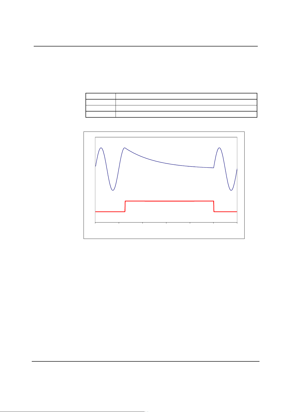
Figure 7 Application and Release of MUTE
The MUTE pin is an input to select mute or not mute. MUTE is active high; taking the pin high
causes the filters to soft mute, ramping down the audio signal over a few milliseconds. Taking
MUTE low again allows data into the filter. Refer to Figure 7.
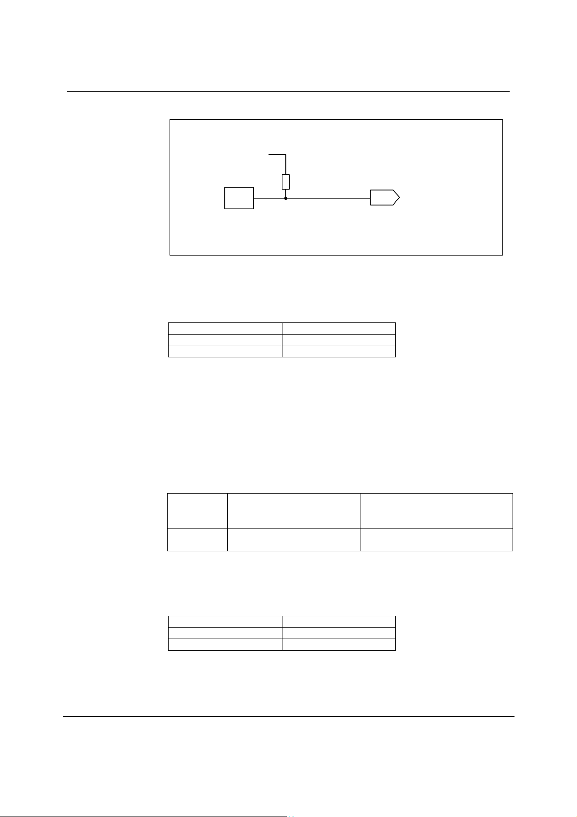
The Infinite Zero Detect (IZD) function detects a series of zero value audio samples of 1024
samples long being applied to both channels. After such an event, a latch is set whose output
(AUTOMUTED) is connected through a 10kohm resistor to the MUTE pin. Thus if the MUTE pin is
not being driven, the automute function will assert mute.
If MUTE is tied low, AUTOMUTED is overridden and will not mute. If MUTE is driven from a bidirectional source, then both MUTE and automute functions are available. If MUTE is not driven,
AUTOMUTED appears as a weak output (10k source impedance) so can be used to drive
external mute circuits. AUTOMUTED will be removed as soon as any channel receives a non-zero
input.
w
PD Rev 4.0 March 2004
13
Page 14
WM8726 Production Data
A diagram showing how the various Mute modes interact is shown below in Figure 8.
AUTOMU TED
(Internal Signal)
10k
ΩΩΩΩ
MUTE
PIN
Figure 8 Selection Logic for MUTE Modes
INPUT AUDIO FORMAT SELECTION
FORMAT (pin 13) controls the data input format.
FORMAT INPU T D ATA M ODE
0 16 bit right justified
1 16–24 bit I2S
Table 3 Input Audio Format Selection
SOFTMUTE
(Internal Signal)
Notes:
2
1. In 16-24 bit I
high for a minimum of data width BCKINs and low for a minimum of data width BCKINs,
unless Note 2. For data widths greater than 24 bits, the LSB’s will be truncated and the
most significant 24 bits will be used by the internal processing.
2. If exactly 16 BCKIN cycles occur in both the low and high period of LRCIN the WM8726 will
assume the data is 16-bit and accept the data accordingly.
S mode, any data from 16-24 bits or more is supported provided that LRCIN is
INPUT DSP FORMAT SELECTION
FORMAT 50% LRCIN DUTY CYCLE LRCIN of 4 BCKIN or Less Duration
0
1
Table 4 DSP Interface Formats
16 bit
(MSB-first, right justified)
2
S format up to 24 bit
I
(Philips serial data protocol)
DSP format – ‘late’ mode
DSP format – ‘early’ mode
DE-EMPHASIS CONTROL
DEM (pin 12) is an input control for selection of de-emphasis filtering to be applied.
DEEMPH DE-EMPHASIS
0 Off
1 On
Table 5 De-emphasis Control
w
PD Rev 4.0 March 2004
14
Page 15
WM8726 Production Data
DIGITAL FILTER CHARACTERISTICS
PARAMETER SYMBOL TEST CONDITIONS MIN TYP MAX UNIT
Passband Edge
Passband Ripple
Stopband Attenuation
-3dB 0.487fs
f < 0.444fs ±0.05 dB
f > 0.555fs -60 dB
Table 6 Digital Filter Characteristics
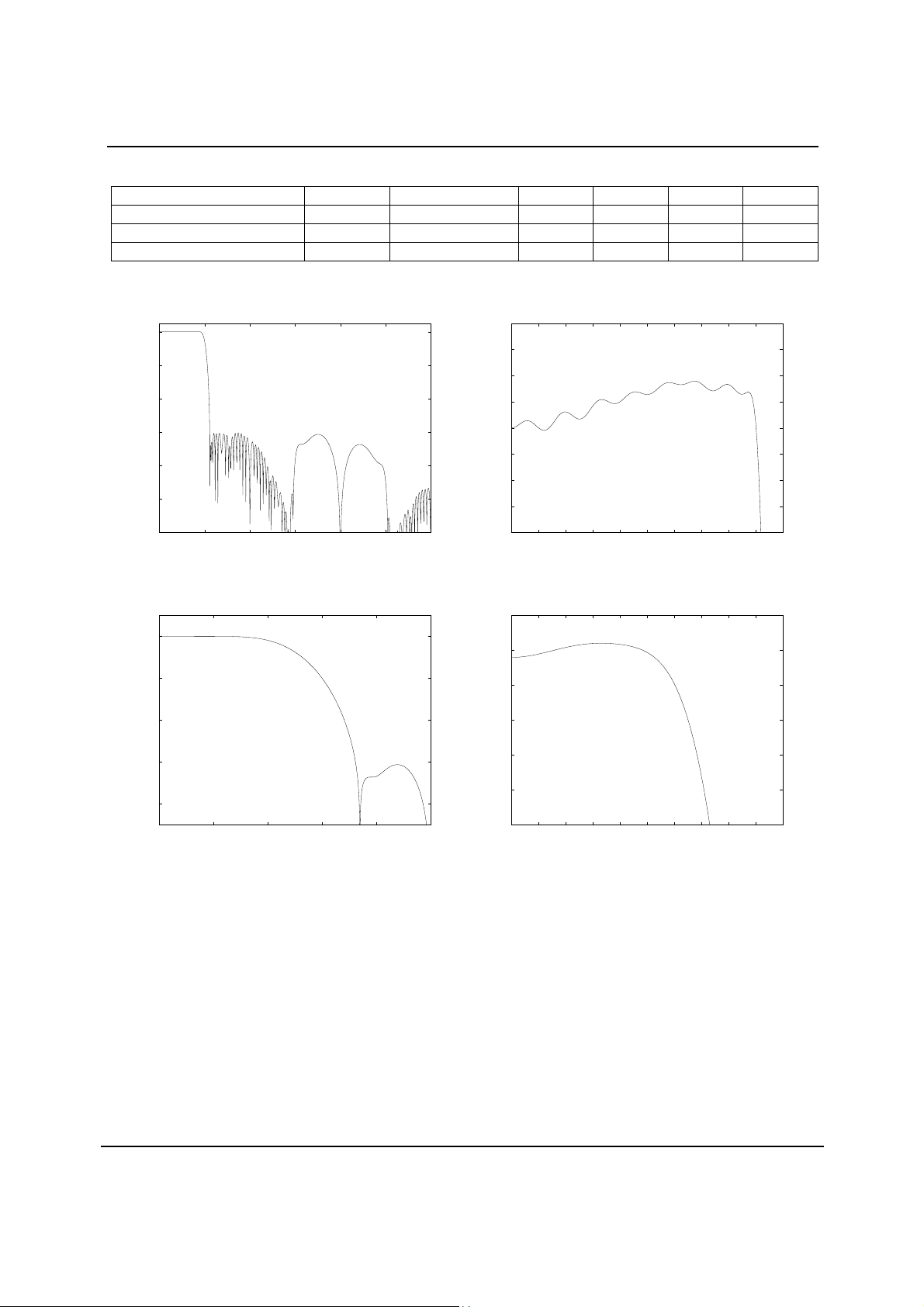
DAC FILTER RESPONSES
0
-20
-40
-60
Response (dB)
-80
-100
-120
0 0.5 1 1.5 2 2.5 3
Frequency (Fs)
Figure 9 DAC Digital Filter Frequency Response
-44.1, 48 and 96kHz
0
0.2
0.15
0.1
0.05
0
Response (dB)
-0.05
-0.1
-0.15
-0.2
0 0.05 0.1 0.15 0.2 0.25 0.3 0.35 0.4 0.45 0.5
Frequency (Fs)
Figure 10 DAC Digital Filter Ripple
-44.1, 48 and 96kHz
0.2
0
-20
-40
Response (dB)
-60
-80
0 0.2 0.4 0.6 0.8 1
Frequency (Fs)
Figure 11 DAC Digital Filter Frequency Response -192kHz
-0.2
-0.4
Response (dB)
-0.6
-0.8
-1
0 0.05 0.1 0.15 0.2 0.25 0.3 0.35 0.4 0.45 0.5
Frequency (Fs)
Figure 12 DAC Digital Filter Ripple -192kHz
w
PD Rev 4.0 March 2004
15
Page 16
WM8726 Production Data
DIGITAL DE-EMPHASIS CHARACTERISTICS
0
-2
-4
-6
Response (dB)
-8
-10
0 2 4 6 8 10 12 14 16
Frequency (kHz)
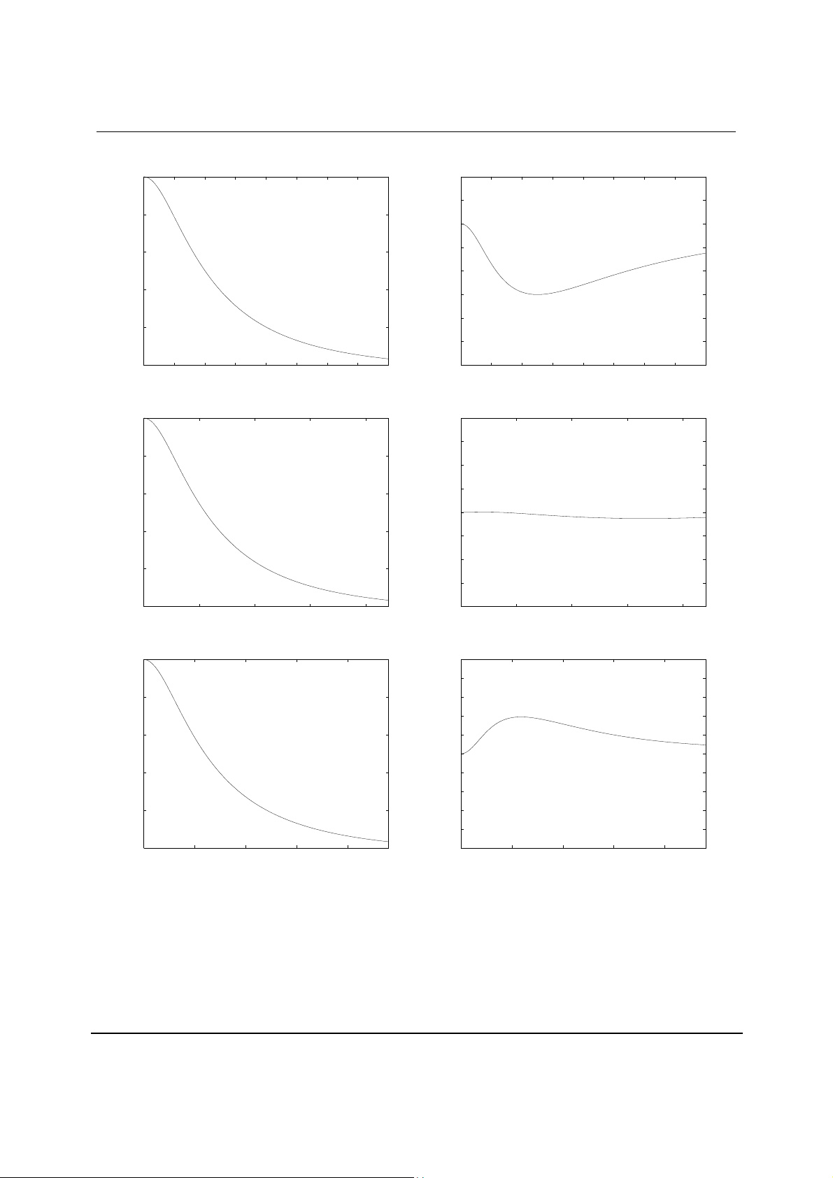
Figure 13 De-Emphasis Frequency Response (32kHz)
0
-2
-4
-6
Response (dB)
-8
-10
0 5 10 15 20
Frequency (kHz)
Figure 15 De-Emphasis Frequency Response (44.1kHz)
0
-2
-4
-6
Response (dB)
-8
-10
0 5 10 15 20
Frequency (kHz)
Figure 17 De-Emphasis Frequency Response (48kHz)
1
0.5
0
-0.5
-1
Response (dB)
-1.5
-2
-2.5
-3
0 2 4 6 8 10 12 14 16
Frequency (kHz)
Figure 14 De-Emphasis Error (32kHz)
0.4
0.3
0.2
0.1
0
Response (dB)
-0.1
-0.2
-0.3
-0.4
0 5 10 15 20
Frequency (kHz)
Figure 16 De-Emphasis Error (44.1kHz)
1
0.8
0.6
0.4
0.2
0
-0.2
Response (dB)
-0.4
-0.6
-0.8
-1
0 5 10 15 20
Frequency (kHz)
Figure 18 De-Emphasis Error (48kHz)
w
PD Rev 4.0 March 2004
16
Page 17
WM8726 Production Data
APPLICATIONS INFORMATION
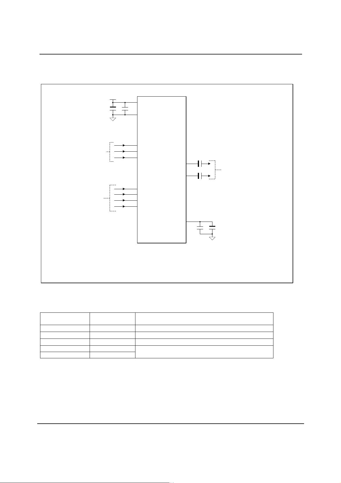
RECOMMENDED EXTERNAL COMPONENTS
Hardware Control
Audio Serial Data I/F
Notes:
1. C2, C5 should be positioned as close to th e WM8726 as possible.
2. Capacitor types should be carefully chosen. Capacitor s with very low ESR are
recommended for optimum performanc e.
3. C3 and C4 not requ ired if using the recomm ended low pass filter in Figure 20.
C
VDD
1
AGND
+
8
VDD
C
2
7
GND
13
FORMAT
12
DEEMPH
10
MUTE
1
LRCIN
14
MCLK
3
BCKIN
2
DIN
VOUTR
WM8726
VOUTL
CAP
C
6
+ +
C
9
5
C
5
Figure 19 External Component Diagram
RECOMMENDED EXTERNAL COMPONENTS VALUES
COMPONENT
REFERENCE
C1 10µF
C2 0.1µF
C3 and C4 10µF
C5 0.1µF
C6 10µF
Table 7 External Components Description
SUGGESTED
VALUE
DESCRIPTION
De-coupling for VDD
De-coupling for VDD
Output AC coupling caps to remove midrail DC level from outputs
Reference de-coupling capacitors for CAP pin
3
AC-Coupled
4
C
6
VOUTR/L
to External LPF
+
AGND
w
PD Rev 4.0 March 2004
17
Page 18
WM8726 Production Data
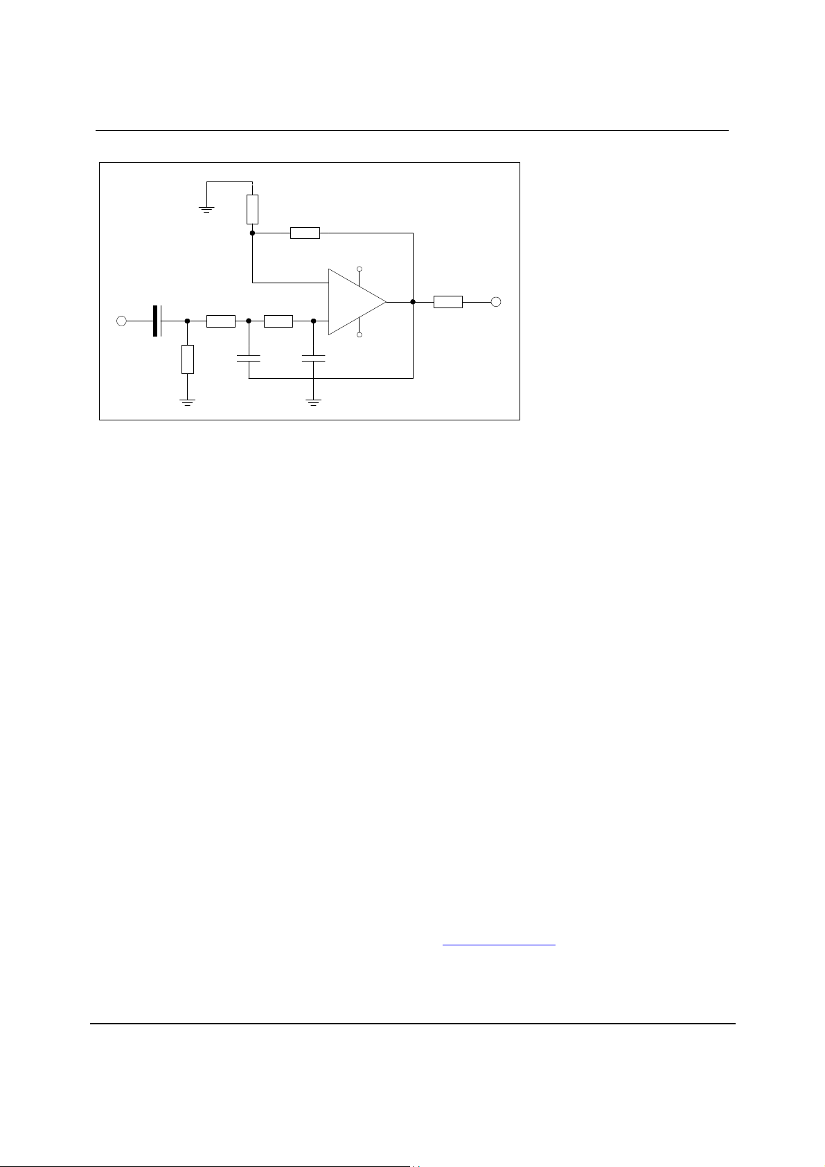
RECOMMENDED ANALOGUE LOW PASS FILTER
4.7k
Ω
4.7k
Ω
+VS
+
10uF
47k
1.8k
Ω
_
7.5K
1.0nF
Ω
+
-VS
680pF
Ω
Ω
51
Figure 20 Recommended 2
nd
Order Low Pass Filter
An external low pass filter is recommended (see Figure 20) if the device is driving a wideband
amplifier. In some applications, a passive RC filter may be adequate.
PCB LAYOUT RECOMMENDATIONS
Care should be taken in the layout of the PCB that the WM8726 is to be mounted to. The
following notes will help in this respect:
1. The VDD supply to the device should be as noise free as possible. This can be
accomplished to a large degree with a 10uF bulk capacitor placed locally to the device and a
0.1uF high frequency decoupling capacitor placed as close to the VDD pin as possible. It is
best to place the 0.1uF capacitor directly between the VDD and GND pins of the device on
the same layer to minimize track inductance and thus improve device decoupling
effectiveness.
2. The CAP pin should be as noise free as possible. This pin provides the decoupling for
the on chip reference circuits and thus any noise present on this pin will be directly coupled
to the device outputs. In a similar manner to the VDD decoupling described in 1. above, this
pin should be decoupled with a 10uF bulk capacitor local to the device and a 0.1uF
capacitor as close to the CAP pin as possible.
3. Separate analogue and digital track routing from each other. The device is split into
analogue (pins 5 – 9) and digital (pins 1 – 4 & pins 10 – 14) sections that allow the routing of
these signals to be easily separated. By physically separating analogue and digital signals,
crosstalk from the PCB can be minimized.
w
4. Use an unbroken solid GND plane. To achieve best performance from the device, it is
advisable to have either a GND plane layer on a multilayer PCB or to dedicate one side of a
2 layer PCB to be a GND plane. For double sided implementations it is best to route as
many signals as possible on the device mounted side of the board, with the opposite side
acting as a GND plane. The use of a GND plane greatly reduces any electrical emissions
from the PCB and minimizes crosstalk between signals.
An evaluation board is available for the WM8726 that demonstrates the above techniques and the
excellent performance achievable from the device. This can be ordered or the User manual
downloaded from the Wolfson web site at www.wolfsonmicro.com
PD Rev 4.0 March 2004
18
Page 19
WM8726 Production Data
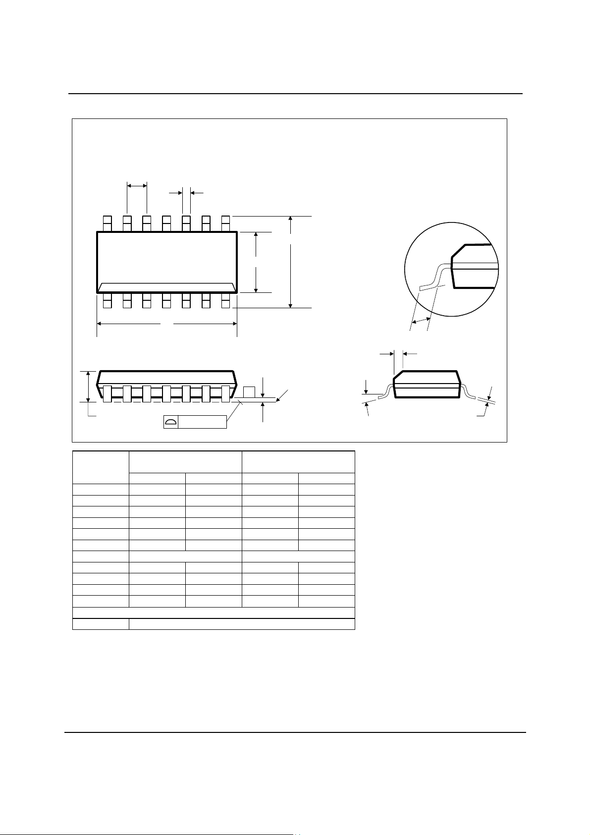
PACKAGE DRAWING
D: 14 PIN SOIC 3.9mm Wide Body
e
14
D
A
B
0.10 (0.004)
DM001.C
8
H
E
71
L
o
h x 45
A1
-C-
SEATING PLANE
α
C
Symbols
Dimensions
(mm)
Dimensions
(Inches)
MIN MAX MIN MAX
A
A1
B
1.35 1.75 0.0532 0.0688
0.10 0.25 0.0040 0.0098
0.33 0.51 0.0130 0.0200
C 0.19 0.25 0.0075 0.0098
D
E
e
8.55 8.75 0.3367 0.3444
3.80 4.00 0.1497 0.1574
1.27 BSC 0.05 BSC
H 5.80 6.20 0.2284 0.2440
h
L
αααα
REF:
NOTES:
A. ALL LINEAR DIMENSIONS ARE IN MILLIMETERS (INCHES).
B. THIS DRAWING IS SUBJECT TO CHANGE WITHOUT NOTIC E.
C. BODY DIMENSIONS DO NOT INCLUDE MOLD FLASH OR PROTRUSION, NOT TO EXCEED 0.25MM (0.010IN).
D. MEETS JEDEC.95 MS-012, VARIATION = AB. REFER TO THIS SPECIFICATION FOR FURTHER DETAILS.
0.25 0.50 0.0099 0.0196
0.40 1.27 0.0160 0.0500
o
0
o
8
o
0
8
JEDEC.95, MS-012
o
w
PD Rev 4.0 March 2004
19
Page 20

WM8726 Production Data
IMPORTANT NOTICE
Wolfson Microelectronics plc (WM) reserve the right to make changes to their products or to discontinue any product or service
without notice, and advise customers to obtain the latest version of relevant information to verify, before placing orders, that
information being relied on is current. All products are sold subject to the WM terms and conditions of sale supplied at the time
of order acknowledgement, including those pertaining to warranty, patent infringement, and limitation of liability.
WM warrants performance of its products to the specifications applicable at the time of sale in accordance with WM’s standard
warranty. Testing and other quality control techniques are utilised to the extent WM deems necessary to support this warranty.
Specific testing of all parameters of each device is not necessarily performed, except those mandated by government
requirements.
In order to minimise risks associated with customer applications, adequate design and operating safeguards must be used by
the customer to minimise inherent or procedural hazards. Wolfson products are not authorised for use as critical components in
life support devices or systems without the express written approval of an officer of the company. Life support devices or
systems are devices or systems that are intended for surgical implant into the body, or support or sustain life, and whose failure
to perform when properly used in accordance with instructions for use provided, can be reasonably expected to result in a
significant injury to the user. A critical component is any component of a life support device or system whose failure to perform
can be reasonably expected to cause the failure of the life support device or system, or to affect its safety or effectiveness.
WM assumes no liability for applications assistance or customer product design. WM does not warrant or represent that any
license, either express or implied, is granted under any patent right, copyright, mask work right, or other intellectual property
right of WM covering or relating to any combination, machine, or process in which such products or services might be or are
used. W M’s publication of information regarding any third party’s products or services does not constitute W M’s approval,
license, warranty or endorsement thereof.
Reproduction of information from the WM web site or datasheets is permissible only if reproduction is without alteration and is
accompanied by all associated warranties, conditions, limitations and notices. Representation or reproduction of this information
with alteration voids all warranties provided for an associated WM product or service, is an unfair and deceptive business
practice, and WM is not responsible nor liable for any such use.
Resale of WM’s products or services with statements different from or beyond the parameters
service voids all express and any implied warranties for the associated WM product or service, is an unfair and deceptive
business practice, and WM is not responsible nor liable for any such use.
stated by WM for that product or
ADDRESS:
Wolfson Microelectronics plc
Westfield House
26 Westfield Road
Edinburgh
EH11 2QB
United Kingdom
Tel :: +44 (0)131 272 7000
Fax :: +44 (0)131 272 7001
Email :: [email protected]
w
PD Rev 4.0 March 2004
20
 Loading...