

Page 1
WM8141
12-bit 6MSPS CIS/CCD Analogue Front End/Digitiser
Production Data, October 2000, Rev 3.0
DESCRIPTION
The WM8141 is a 12-bit analogue front end/digitiser that
processes and digitises the analogue output signals from
CCDs or Contact Image Sensors (CIS). The devi ce can be
operated as either a three channel or a single channel
device at pixel sample rates of up to 6MSPS. The device
has both external and programmable internal black level
reference options for CIS operation. The W M8141 runs off a
single supply voltage of eit her 3.3V or 5V. Alternat ively, the
device can be operated from split 5V c ore and 3.3V digital
interface supplies.
The WM8141 includes three analogue signal processing
channels each of which contains reset level clamping,
correlated double sampling and programmable offset and
gain adjust facilities. Each of these channels is time
multiplexed into a single high-s peed 12-bit resolution ADC,
which digitises the pixel image inform ation. The digital data
output is available to the user in either 12-bit parallel or
8/6/4-bit wide multiplexed form ats.
The internal control registers are programmable via a
convenient serial or parallel digital i nterface. The WM8141
typically consumes only 45mA and less t han 10µA when in
power down mode.
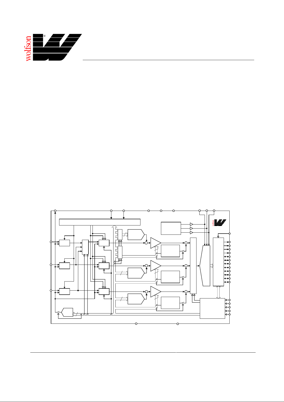
BLOCK DIAGRAM
VSMP
VRLC/VBIAS
(18)
(27)
MCLK
(28)
FEATURES
• 12-bit resolution ADC
• 6MSPS conversion rate at 5V supply
• 5V or 3.3V single supply or 5V/ 3.3V dual supply operation
• Single or 3 channel operation
• Correlated double sampling
• Programmable gain (8-bit resolution)
• Programmable offs et adjust (8-bit resolution)
• 12-bit parallel or 8/6/4-bit wide mul t i pl exed output bus
• Internally generated voltage references
• External or internal reference for CIS operation
• Low power – 225mW typical at 5V supply
• Interface and timing compatible with WM8143, WM8144
and WM8142 devices
• Drop in replacement for WM8143-12
• 32-pin TQFP package
APPLICATIONS
• Flatbed and sheetfeed scanners
• USB compatible s canners
• Multi-function peripherals
• CCD sensor interface
• Contact image sensor (CIS) interface
VRX
AVDD
(12)
DVDD1
(14)
DVDD2
(32)
VRT
(16)
(17)
VRB
(15)
TIMING CONTROLCL
V
R
S
S
R
M
U
G
X
RINP (21)
GINP (20)
BINP (19)
RLC
RLC
RLC
RLC
DAC
M
U
X
4
CDS
CDS
CDS
B
R
M
U
G
X
B
8
8
WOLFSON MICROELECTRONICS LTD
Lutton Court, Bernard Terrace, Edi nburgh, EH8 9NX, UK
Tel: +44 (0) 131 667 9386
Fax: +44 (0) 131 667 5176
Email: [email protected]
http://www.wolfson.co.uk
8
OFFSET
DAC
OFFSET
DAC
OFFSET
DAC
(13)
AGND
VREF/BIAS
PGA
+
+
+
8
PGA
8
PGA
8
I/P SIGNAL
POLARITY
ADJUST
I/P SIGNAL
POLARITY
ADJUST
I/P SIGNAL
POLARITY
ADJUST
(29)
DGND
+
M
+
U
X
+
WM8141
DATA
I/O
12
PORT
BIT
ADC
CONFIGURABLE
SERIAL/
PARALLEL
CONTROL
INTERFACE
(22) OEB
(30) OP[0]
(31) OP[1]
(1) OP[2]
(2) OP[3]
(3) OP[4]
(4) OP[5]
(5) OP[6]
(6) OP[7]
(7) OP[8]
(8) OP[9]
(9) OP[10]
(10) OP[11]/SDO
(23) SEN/STB
(25) SCK/RNW
(24) SDI/DNA
(26) RLC/ACYC
(11) NRESET
Production Data Datasheets contain final
specifications current on publication date.
Supply of products conforms to Wol fson
Microelectronics’ Term s and Conditions.
2000 Wolfson Microelectronics Ltd.
Page 2
WM8141 Production Data PIN CONFIGURATION ORDERING INFORMATION
DEVICE TEMP. RANGE PACKAGE
DVDD2
SCK/RNW
OP[1]
OP[0]
DGND
RLC/ACYC
MCLK
VSMP
WM8141CFT/V 0 to 70°C 32-pin TQFP
OP[2]
OP[3]
OP[4]
OP[5]
OP[6]
OP[7]
OP[8]
OP[9]
1
2
3
4
5
6
7
8
10 11 121314 15
OP[10]
NRESET
OP[11]/SDO
AVDD
2532 31 30 29 28 27 26
169
VRB
AGND
DVDD1
SDI/DNA
24
SEN/STB
23
OEB
22
RINP
21
GINP
20
BINP
19
VRLC/VBIAS
18
VRX
17
VRT
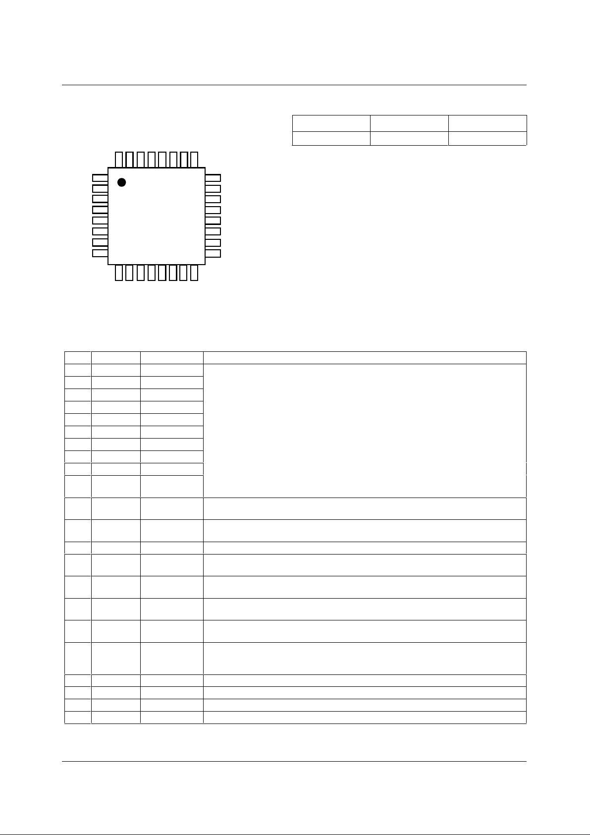
PIN DESCRIPTION
PIN NAME TYPE DESCRIPTION
1 OP[2] Digital output
2 OP[3] Digital output
3 OP[4] Digital IO
4 OP[5] Digital IO
5 OP[6] Digital IO
6 OP[7] Digital IO
7 OP[8] Digital IO
8 OP[9] Digital IO
9 OP[10] Digital IO
10 OP[11]/
Digital IO
SDO
11 NRESET Digital input
12 AVDD Supply
13 AGND Supply
14 DVDD1 Supply
15 VRB Analogue output
16 VRT Analogue output
17 VRX Analogue output
18 VRLC/
Analogue IO
VBIAS
19 BINP Analogue input
20 GINP Analogue input
21 RINP A nal ogue i nput
22 OEB Digital input
Hi-Z digital 12-bit bi-directi onal bus. There are several modes:
Hi-Z: when OEB = 1.
12-bit output: 12-bit data is out put on OP[11:0].
8-bit multiplexed output: data i s output on OP[11:4] at 2 ∗ ADC conversion rate.
6-bit multiplexed output: data i s output on OP[11:6] at 2 ∗ ADC conversion rate.
4-bit multiplexed output: data i s output on OP[11:8] at 4 ∗ ADC conversion rate.
Input 8-bit: control data i s input on OP[11:4] in parallel mode when SCK/RNW = 0,
and SEN/STB = 0.
Output 8-bit: register read back data is output in parallel on OP[ 11:4] when
SCK/RNW = 1, and SEN/STB = 0, or in serial on pin SDO when SEN/STB = 1.
Reset input, active low. This signal forces a reset of al l i nternal registers and selects
whether the serial or parallel control bus i s used (see SEN/STB).
Analogue supply (3.3/5V) for CDS, PGA and OFFSET blocks. This must be operated at
the same potential as DVDD1.
Analogue ground (0V).
Digital supply (3.3/5V) for l ogi c and clock generator. This must be operated at the same
potential as AVDD.
Lower reference voltage. This pin mus t be connected to AGND via a decoupli ng
capacitor.
Upper reference voltage. This pin must be connected to AGND vi a a decoupling
capacitor.
Input return bias voltage. This pin must be connected to AGND via a decoupling
capacitor.
Selectable analogue output voltage for RLC or single-ended bias reference. This pin
would typically be connected to AGND via a decoupling capacitor. VRLC can be
externally driven if programmed Hi-Z.
Blue channel input video.
Green channel input video.
Red channel input video.
Output Hi-Z control: all output s disabled when OEB = 1.
WOLFSON MICROELECTRONICS LTD PD Rev 3.0 October 2000
2
Page 3
Production Data WM8141
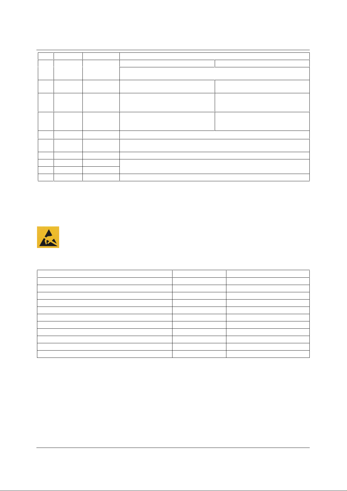
PIN NAME TYPE DESCRIPTION
23 SEN/STB Digital input
24 SDI/DNA Digital input
25 SCK/RNW Digital input
26 RLC/
ACYC
27 VSMP Digital input
28 MCLK Digital input
29 DGND Supply
30 OP[0] Digital output
31 OP[1] Digital output
32 DVDD2 Supply
Digital input
Serial Interface: Enabl e pul se, active high. Parallel Interface: S trobe, active low.
Latched on NRESET rising edge: If Low then device control is via serial int erface,
if High then device control i s via parallel interface.
Serial Interface: Seri al i nput
data signal.
Serial Interface: Seri al clock signal. Parallel Interface:
Selects whether Reset Level Clamp is
applied (active high). If RLC is required on
every pixel then this pin can be tied high.
Video sample synchronis ation pulse.
Master clock. This clock is applied at N times the input pixel rate (N = 8, 6, 3 or 2
depending on the input sampling mode).
Digital ground (0V).
Hi-Z digital 12-bit bi-directional bus, see description for pins OP[2] to OP[11]/SDO.
Digital supply (3.3/5V) f or all digital pins.
Parallel Interface: High = data,
Low = address.
High = OP[11:4] is output bus ,
Low = OP[11:4] is input bus (Hi-Z)
ACYC, auto-cycles between RINP , GINP,
BINP when in line by line mode.
ABSOLUTE MAXIMUM RATINGS
Absolute Maximum Ratings are s tres s rat ings only. P erm anent damage to the device may be c aused by c onti nuously operat ing at
or beyond these limits. Device functional operating lim its and guaranteed performance s pecifications are gi ven under Electrical
Characteristics at the test conditions s pecified
ESD Sensitive Device. Thi s device i s m anufactured on a CMOS process . It i s t herefore generi cally suscept ible
to damage from excessi ve stati c voltages . Proper ES D precautions mus t be tak en during handling and st orage
of this device.
As per JEDEC specifications A112-A and A113-B, this product requires specific storage conditions prior to surface mount
assembly. It has been classified as having a Moisture Sensitivity Level of 2 and as such will be supplied in vacuum-sealed
moisture barrier bags.
CONDITION MIN MAX
Analogue supply voltage: AVDD
Digital supply voltages: DVDD1, DVDD2
Digital ground: DGND
Analogue ground: AGND
Digital inputs, digit al out puts and digital pins
Analogue inputs (RINP, GINP , BINP)
Other pins
Operating temperature range: T
Storage temperature
Package body temperature (s ol deri ng, 10 seconds)
Package body temperature (s ol deri ng, 2 minutes)
Notes: 1. GND denotes t he vol t age of any ground pin.
2. AGND and DGND pins are intended to be operated at the same potential. Diff erential voltages between these pins
will degrade performance.
3. AVDD and DVDD1 pins are intended to be operated at t he same potential. Differential voltages between these pins
will degrade performance.
A
GND - 0.3V GND + 7V
GND - 0.3V GND + 7V
GND - 0.3V GND + 0.3V
GND - 0.3V GND + 0.3V
GND - 0.3V DVDD2 + 0.3V
GND - 0.3V AVDD + 0.3V
GND - 0.3V AVDD + 0.3V
0°C+70°C
-50°C +150°C
+240°C
+183°C
WOLFSON MICROELECTRONICS LTD PD Rev 3.0 October 2000
3
Page 4
WM8141 Production Data
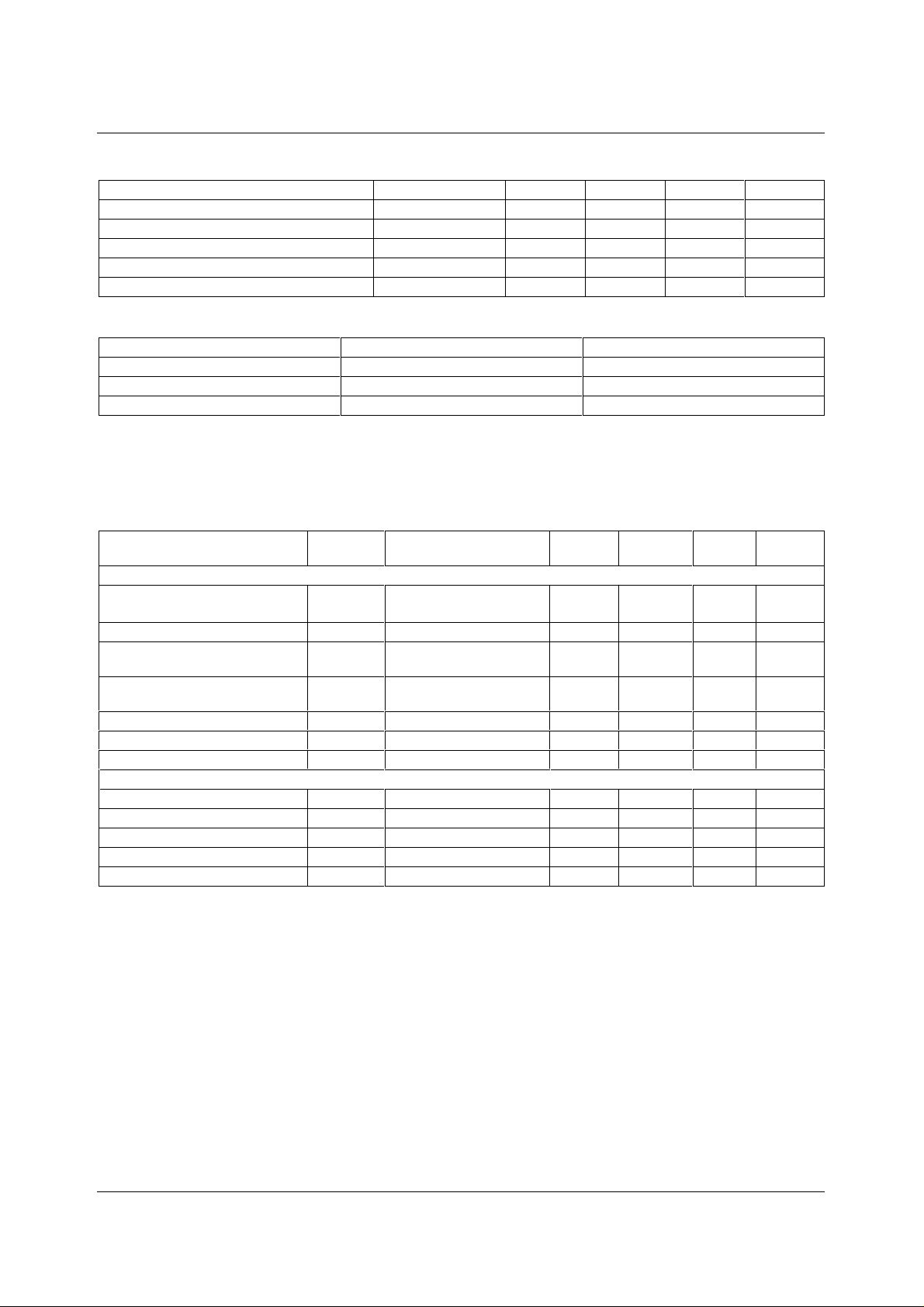
RECOMMENDED OPERATING CONDITIONS
CONDITION SYMBOL MIN TYP MAX UNITS
Operating temperature range
Digital supply voltages (5V operation)
Digital supply voltages (3. 3V operation)
Analogue supply voltage (5V operation)
Analogue supply voltage (3.3V operati on)
T
A
DVDD1, DVDD2 4.75 5 5.25 V
DVDD1, DVDD2 2.97 3.3 3.63 V
AVDD 4.75 5 5.25 V
AVDD 2.97 3.3 3.63 V
070°C
POSSIBLE POWER SUPPLY COMBINATIONS
COMBINATION AVDD, DVDD1 (VOLTS) DVDD2 (VOLTS)
155
253.3
33.33.3
ELECTRICAL CHARACTERISTICS
ANALOGUE CHARACTERISTICS (5V OPERATION)
Test Conditions
AVDD = DVDD1 = DVDD2 = 4.75 to 5.25V, AGND = DGND = 0V, T
PARAMETER SYMBOL TEST
Overall System Specification Including CDS, PGA, OFFSET and ADC Functions. No Missing Codes Guaranteed.
Full-scale input voltage range
(see Note 1)
Input signal limits (see Note 2)
Full-scale transition error
Zero-scale transition error
Differential non-linearity
Integral non-linearity
Channel to channel gain matchi ng
References
Upper reference voltage
Lower reference voltage
Input return bias voltage
Diff. reference voltage (VRT-VRB)
Output resistance VRT, V RB , VRX
V
IN
DNL 0.5 1 LSB
INL 2 LSB
VRT 2.70 2.85 3.00 V
VRB 1.25 1.35 1.45 V
VRX 0.60 0.65 0.70 V
V
RTB
CONDITIONS
Max Gain
Min Gain
Gain = 0dB;
PGA[7:0] = 4B(hex)
Gain = 0dB;
PGA[7:0] = 4B(hex)
= 0 to 70°C, MCLK = 12MHz unless otherwise stated.
A
MIN TYP MAX UNIT
0.4
4.08
0 AVDD V
20 mV
20 mV
1%
1.4 1.5 1.6 V
1 Ω
Vp-p
Vp-p
WOLFSON MICROELECTRONICS LTD PD Rev 3.0 October 2000
4
Page 5
Production Data WM8141
Test Conditions
AVDD = DVDD1 = DVDD2 = 4.75 to 5.25V, AGND = DGND = 0V, T
PARAMETER SYMBOL TEST
= 0 to 70°C, MCLK = 12MHz unless otherwise stated.
A
MIN TYP MAX UNIT
CONDITIONS
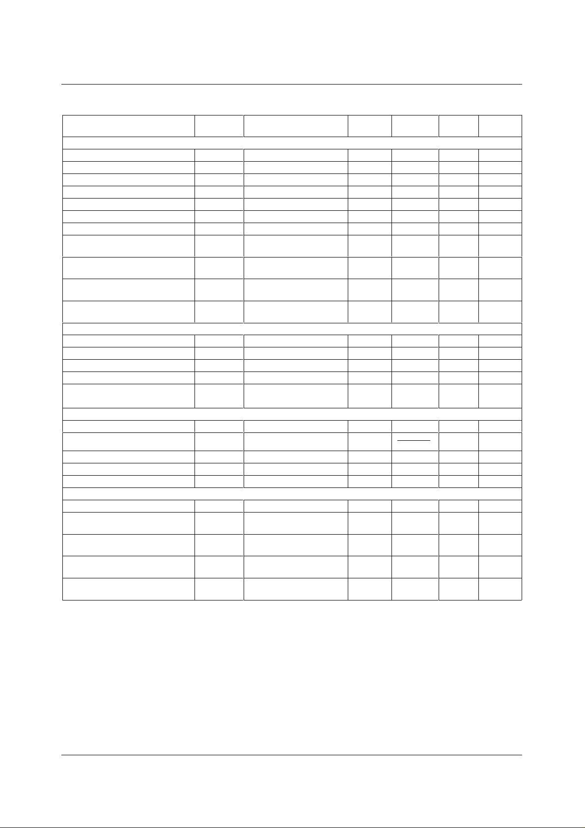
VRLC/Reset-Level Clamp (RLC)
RLC switching impedance
VRLC short-circuit c urrent
VRLC output resistance
VRLC Hi-Z leakage current
RLCDAC resolution
RLCDAC step size, RLCDAC = 0
RLCDAC step size, RLCDAC = 1
RLCDAC output voltage at
V
RLCSTEP
V
RLCSTEP
V
RLCBOT
50 Ω
5mA
2 Ω
1 µA
4bits
0.24 V/step
0.16 V/step
0.4 V
code 0(hex), RLCDACRNG = 0
RLCDAC output voltage at
V
RLCBOT
0.25 V
code 0(hex), RLCDACRNG = 1
RLCDAC output voltage at
V
RLCTOP
4.2 V
code F(hex) RLCDACRNG, = 0
RLCDAC output voltage at
V
RLCTOP
2.85 V
code F(hex), RLCDACRNG = 1
Offset DAC, Monotonicity Guaranteed
Resolution
Differential non-linearity
Integral non-linearity
Step size
Output voltage
DNL 0.1 0.5 LSB
INL 0.25 1 LSB
Code 00(hex)
Code FF(hex)
8bits
2.04 mV/step
-260
+260
mV
mV
Programmable Gain Amplifier
Resolution
Gain
Max gain, each channel
Min gain, each channel
Gain error, each channel
G
MAX
G
MIN
8bits
208
]0:7[PGA283
−
V/V
7.4 V/V
0.74 V/V
15%
Supply Currents
Total supply current – active
Total analogue supply current –
I
AVDD
45 65 mA
42 mA
active
Digital logic supply c urrent,
2mA
DVDD1 – active
Digital I/O supply c urrent,
1mA
DVDD2 – active
Supply current – full power down
10 µA
mode
Notes: 1. Full-scale input voltage denotes the maximum amplitude of the input signal at the specified gain.
2. Input signal limits are the limits within which the full-scale input voltage signal must lie.
WOLFSON MICROELECTRONICS LTD PD Rev 3.0 October 2000
5
Page 6
WM8141 Production Data
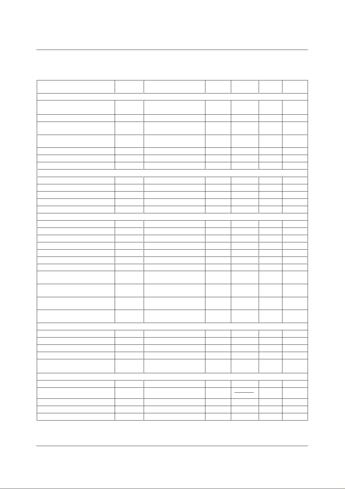
ANALOGUE CHARACTERISTICS (3.3V OPERATION)
Test Conditions
AVDD = DVDD1 = DVDD2 = 2.97V to 3.63V, AGND = DGND = 0V, T
PARAMETER SYMBOL TEST
CONDITIONS
Overall System Specification Including CDS, PGA, OFFSET and ADC Functions.
Full-scale input voltage range
(see Note 1)
Input signal limits (see Note 2)
Full-scale transition error
V
IN
Max Gain
Min Gain
Gain = 0dB;
PGA[7:0] = 4B(hex)
Zero-scale transition error
Gain = 0dB;
PGA[7:0] = 4B(hex)
Differential non-linearity
Integral non-linearity
DNL 0.5 LSB
INL 2 LSB
Channel to channel gain matchi ng
References
Upper reference voltage
Lower reference voltage
Input return bias voltage
Diff. reference voltage (VRT-VRB)
VRT 1.625 1.725 1.825 V
VRB 0.900 0.975 1.050 V
VRX 0.60 0.65 0.70 V
V
RTB
Output resistance VRT, V RB , VRX
VRLC/Reset-Level Clamp (RLC)
RLC switching impedance
VRLC short-circuit c urrent
VRLC output resistance
VRLC Hi-Z leakage current
RLCDAC resolution
RLCDAC step size, RLCDAC = 0
RLCDAC step size, RLCDAC = 1
RLCDAC output voltage at
V
RLCSTEP
V
RLCSTEP
V
RLCBOT
code 0(hex), RLCDACRNG = 0
RLCDAC output voltage at
V
RLCBOT
code 0(hex), RLCDACRNG = 1
RLCDAC output voltage at
V
RLCTOP
code F(hex), RLCDACRNG = 0
RLCDAC output voltage at
V
RLCTOP
code F(hex), RLCDACRNG = 1
Offset DAC
Resolution
Differential non-linearity
Integral non-linearity
DNL 0.1 LSB
INL 0.25 LSB
Step size
Output voltage
Code 00(hex)
Code FF(hex)
Programmable Gain Amplifier
Resolution
Gain
Max gain, each channel
Min gain, each channel
G
MAX
G
MIN
Gain error, each channel
Notes: 1. Full-scale input voltage denotes the maxim um amplitude of the input signal at the specifi ed gai n.
2. Input signal limits are the limits within which the full-s cale input voltage signal m ust lie.
= 0 to 70°C, MCLK = 8MHz unless otherwise stat ed.
A
MIN TYP MAX UNIT
0.2
2.04
0 AVDD V
20 mV
20 mV
1%
0.65 0.75 0.85 V
1 Ω
140 Ω
5mA
2 Ω
<0.1 µA
4bits
0.16 V/step
0.09 V/step
0.25 V
0.2 V
2.75 V
1.7 V
8bits
1.02 mV/step
-130
+130
8bits
208
]0:7[PGA283
−
7.4 V/V
0.74 V/V
1%
Vp-p
Vp-p
mV
mV
V/V
WOLFSON MICROELECTRONICS LTD PD Rev 3.0 October 2000
6
Page 7
Production Data WM8141
Test Conditions
AVDD = DVDD1 = DVDD2 = 2.97V to 3.63V, AGND = DGND = 0V, T
PARAMETER SYMBOL TEST
= 0 to 70°C, MCLK = 8MHz unless otherwise stat ed.
A
MIN TYP MAX UNIT
CONDITIONS
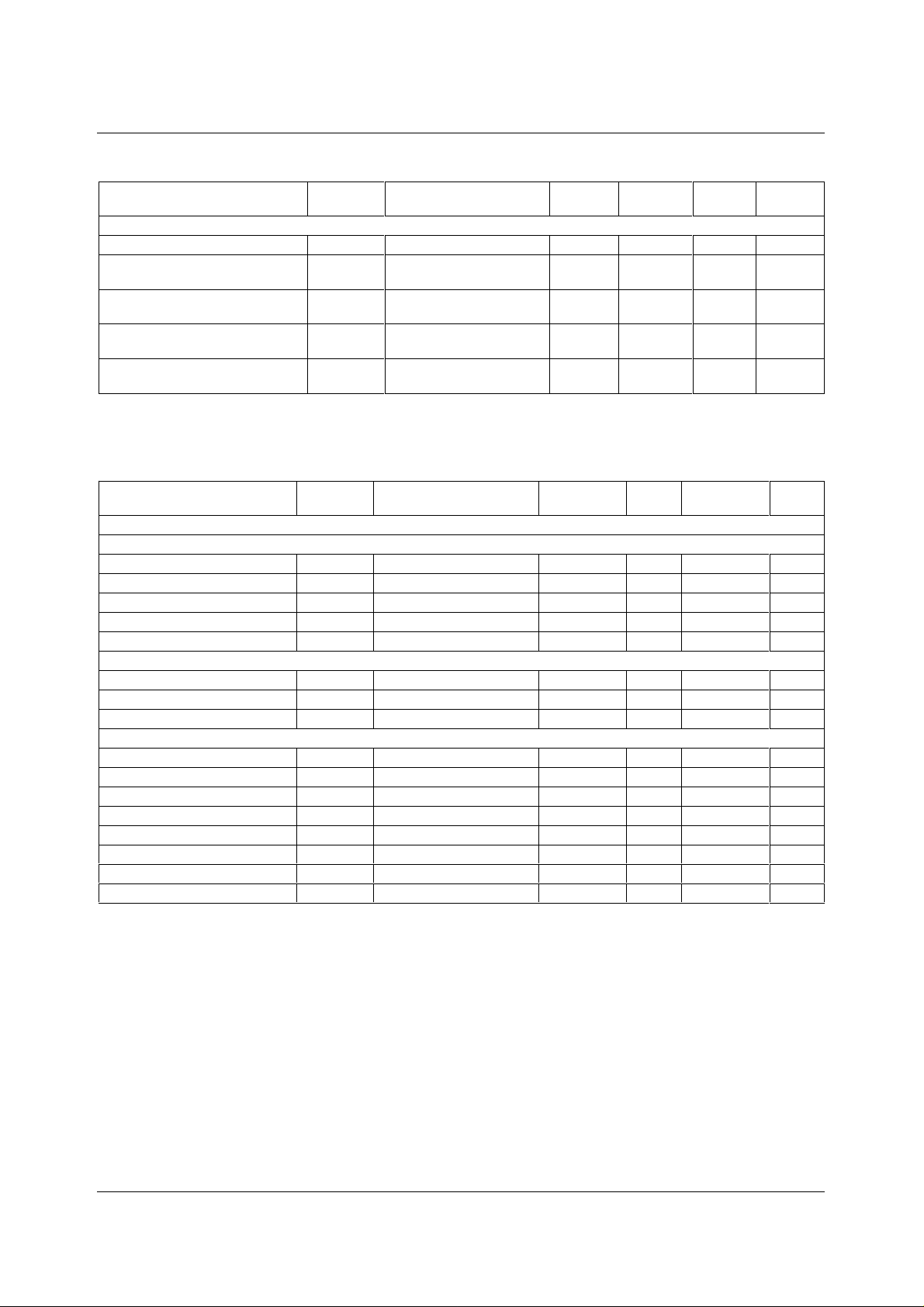
Supply Currents
Total supply current – active
Total analogue supply current –
I
AVDD
43 mA
40 mA
active
Digital logic supply c urrent,
2mA
DVDD1 – active
Digital I/O supply c urrent,
1mA
DVDD2 – active
Supply current – full power down
10 µA
mode
DIGITAL CHARACTERISTICS
Test Conditions
AVDD = DVDD1 = DVDD2 = 2.97V to 5.25V, AGND = DGND = 0V, T
PARAMETER SYMBOL TEST
CONDITIONS
DIGITAL SPECIFICATIONS
Digital Inputs
High level input voltage
Low level input voltage
High level input current
Low level input current
Input capacitance
V
IH
V
IL
I
IH
I
IL
C
I
Digital Outputs
High level output voltage
Low level output voltage
High impedance output current
V
OH
V
OL
I
OZ
IOH = 1mA DVDD2 - 0. 5 V
IOL = 1mA 0.5 V
Digital IO Pins
Applied high level input voltage
Applied low level input voltage
High level output voltage
Low level output voltage
Low level input current
High level input current
Input capacitance
High impedance output current
V
IH
V
IL
V
OH
V
OL
I
IL
I
IH
C
I
I
OZ
IOH = 1mA DVDD2 - 0. 5 V
IOL = 1mA 0.5 V
= 0 to 70°C, MCLK = 12MHz unless otherwise stated.
A
MIN TYP MAX UNIT
0.8 ∗ DVDD2 V
0.2 ∗ DVDD2 V
1 µA
1 µA
5pF
1 µA
0.8 ∗ DVDD2 V
0.2 ∗ DVDD2 V
1 µA
1 µA
5pF
1 µA
WOLFSON MICROELECTRONICS LTD PD Rev 3.0 October 2000
7
Page 8
WM8141 Production Data
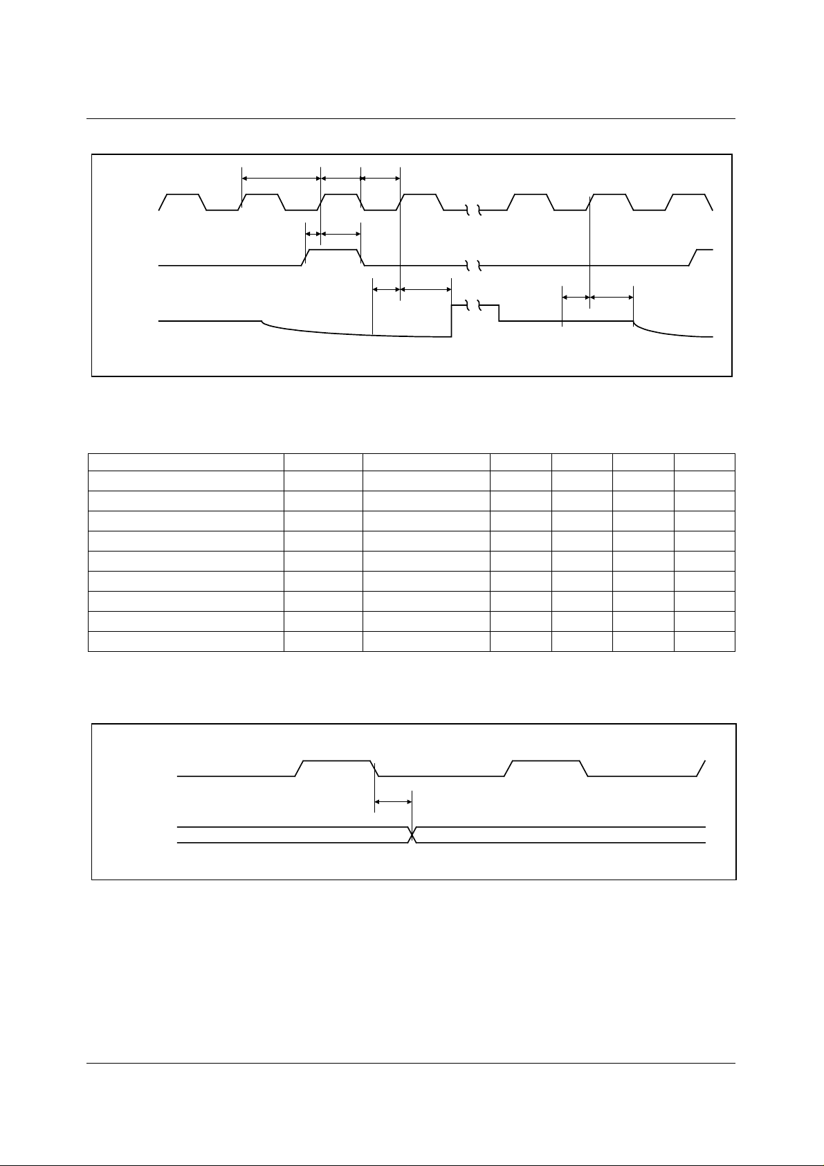
INPUT VIDEO SAMPLING
t
PER
t
MCLKH
t
MCLKL
MCLK
t
VSMPSU
t
VSMPH
VSMP
INPUT
t
VSUtVH
t
RSUtRH
VIDEO
Figure 1 Input Video Timing
Test Conditions
AVDD = DVDD1 = DVDD2 = 4.75 to 5.25V, AGND = DGND = 0V, T
= 0 to 70°C, MCLK = 12MHz unless otherwise stat ed
A
PARAMETER SYMBOL TEST CONDITIONS MIN TYP MAX UNITS
MCLK period
MCLK high period
MCLK low period
VSMP set-up time
VSMP hold time
Video level set-up tim e
Video level hold time
Reset level set-up time
Reset level hold time
Notes: 1. t
VSU
and t
denote the set-up time requi red af ter the input video signal has set tled.
RSU
t
PER
t
MCLKH
t
MCLKL
t
VSMPSU
t
VSMPH
t
VSU
t
VH
t
RSU
t
RH
83.3 ns
37.5 ns
37.5 ns
10 ns
10 ns
10 ns
15 ns
10 ns
15 ns
2. Parameters are measured at 50% of the rising/falling edge.
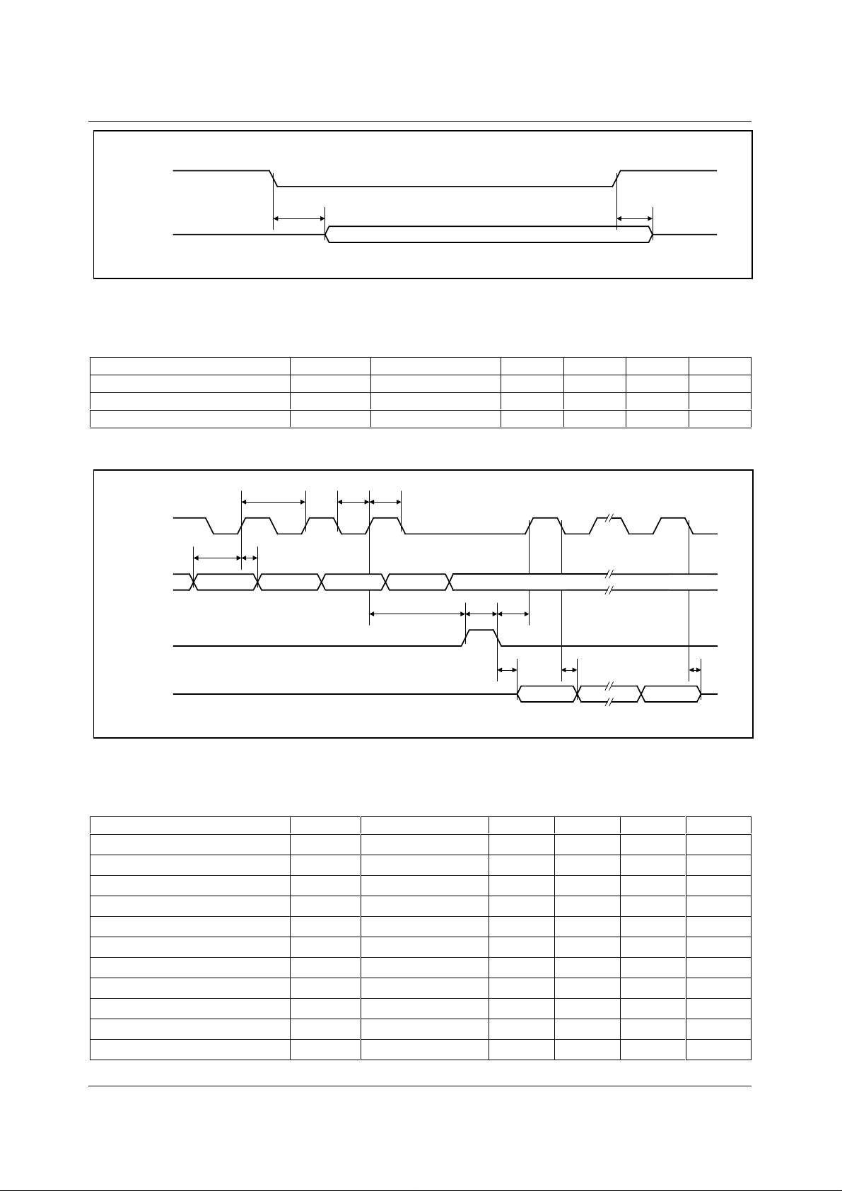
OUTPUT DATA TIMING
MCLK
t
PD
OP[11:0]
Figure 2 Output Data Timing
WOLFSON MICROELECTRONICS LTD PD Rev 3.0 October 2000
8
Page 9
Production Data WM8141
OEB
OP[11:0]
Hi-Z
t
PZE
t
PEZ
Hi-Z
Figure 3 Output Data Enable Timing
Test Conditions
AVDD = DVDD1 = DVDD2 = 4.75 to 5.25V, AGND = DGND = 0V, T
= 0 to 70°C, MCLK = 12MHz unless otherwise stat ed
A
PARAMETER SYMBOL TEST CONDITIONS MIN TYP MAX UNITS
Output propagation delay t
Output enable time t
Output disable time t
PD
PZE
PEZ
I
OH
= 1mA, I
= 1mA 75
OL
50
25
SERIAL INTERFACE
SCK
SDI
t
SPER
t
SSU
t
SH
t
SCKLtSCKH
t
SCE
t
SEWtSEC
ns
ns
ns
SEN
SDO
t
SESD
MSB LSB
t
SCSD
t
SCSDZ
Figure 4 Serial Interface Timing
Test Conditions
AVDD = DVDD1 = DVDD2 = 4.75 to 5.25V, AGND = DGND = 0V, T
= 0 to 70°C, MCLK = 12MHz unless otherwise stat ed
A
PARAMETER SYMBOL TEST CONDITIONS MIN TYP M AX UNITS
SCK period
SCK high
SCK low t
SDI set-up time
SDI hold time
SCK to SEN set-up time
SEN to SCK set-up time
SEN pulse width
SEN low to SDO out
SCK low to SDO out
SCK low to SDO high impedance
t
SPER
t
SCKH
SCKL
t
SSU
t
SH
t
SCE
t
SEC
t
SEW
t
SESD
t
SCSD
t
SCSDZ
83.3 ns
37.5 ns
37.5 ns
10 ns
10 ns
20 ns
20 ns
50 ns
35 ns
35 ns
25 ns
Note: Parameters are measured at 50% of the rising/falling edge.
WOLFSON MICROELECTRONICS LTD PD Rev 3.0 October 2000
9
Page 10
WM8141 Production Data
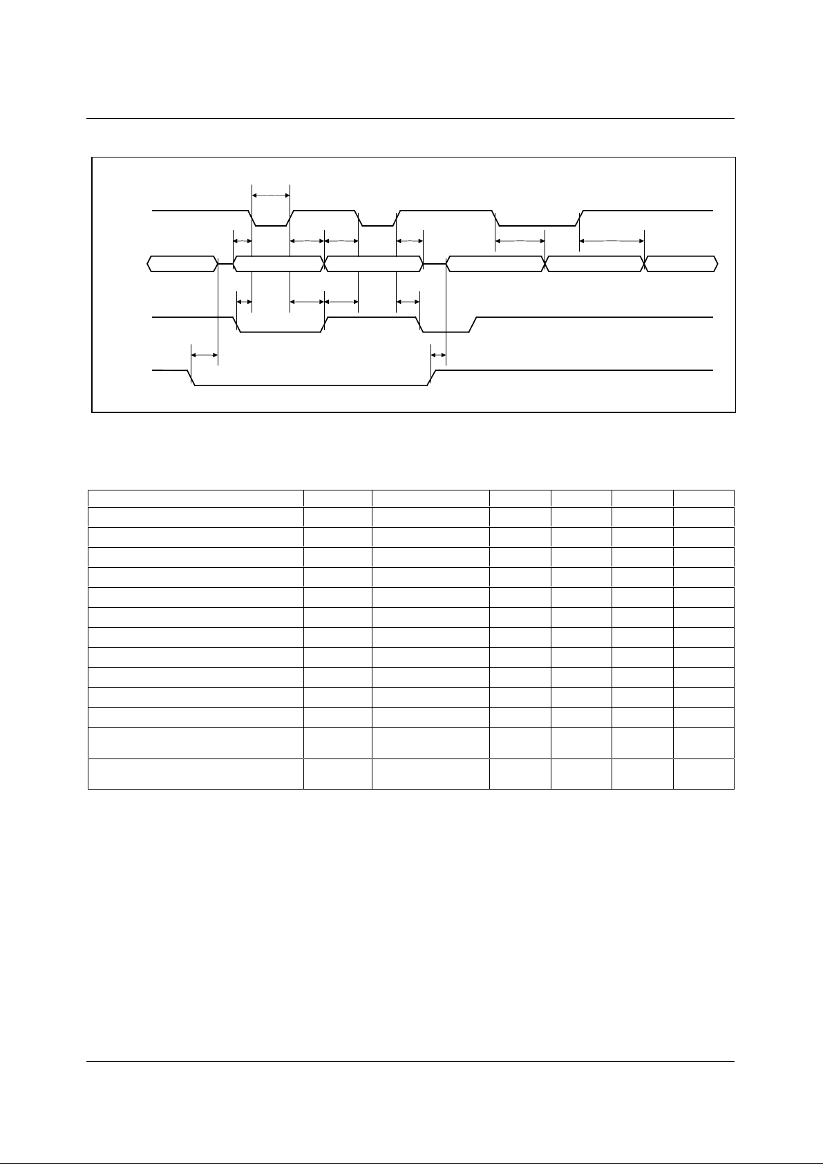
PARALLEL INTERFACE
t
STB
STB
OP[11:4]
ADC DATA OUT
t
ASU
Hi-Z
ADDRESS IN
t
ADLStADLHtADHStADHH
t
AHtDSU
DATA IN
t
DH
t
STDO
t
STAO
Hi-Z
ADC DATA OUT REG. DATA OUT
ADC DATA OUT
DNA
t
OPZ
t
OPD
RNW
Figure 5 Parallel Interface Diagram
Test Conditions
AVDD = DVDD1 = DVDD2 = 4.75 to 5.25V, AGND = DGND = 0V, T
= 0 to 70°C, MCLK = 12MHz unless otherwise stat ed
A
PARAMETER SYMBOL TEST CONDITIONS MIN TYP MAX UNITS
RNW low to OP[11:4] tri-state.
Address set-up time to STB low
DNA low set-up time to STB low
Strobe low time
Address hold time f rom STB high
DNA low hold time from S TB high
Data set-up time to STB low
DNA high set-up time to STB low
Data hold time from STB high
Data high hold time from STB high
RNW high to OP[11: 4] output
Data output propagation delay from STB
t
OPZ
t
ASU
t
ADLS
t
STB
t
t
ADLH
t
DSU
t
ADHS
t
t
ADHH
t
OPD
t
STDO
20 ns
0ns
10 ns
50 ns
AH
10 ns
10 ns
0ns
10 ns
DH
10 ns
10 ns
35 ns
35 ns
low
ADC data out propagation delay from
t
STAO
35 ns
STB high
Note: Parameters are measured at 50% of the rising/falling edge.
WOLFSON MICROELECTRONICS LTD PD Rev 3.0 October 2000
10
Page 11

Production Data WM8141
DEVICE DESCRIPTION
INTRODUCTION
A block diagram of t he devi ce showing the signal path is presented on P age 1.
The WM8141 samples up to three inputs (RINP, GINP and B INP) simultaneousl y. The device then
processes the sam pled video signal with respect to the video reset level or an internally/externally
generated reference level using either one or t hree processing channels.
Each processing channel consis ts of an Input Sampling block with opti onal Reset Level Clamping
(RLC) and Correlated Double Sampling (CDS), an 8-bit programmable offset DAC and an 8-bit
Programmable Gain Amplifier (PGA).
The ADC then converts each result i ng anal ogue signal to a 12-bit digital word. The di gi tal output from
the ADC is presented on a 12-bit wide bi-direct ional bus, with optional 8+4-bit, 6+6-bit or 4+4+4-bit
multiplexed formats.
On-chip control registers determine t he configuration of the device, including t he offsets and gains
applied to each channel. These registers are programmable via s eri al or paral l el interfaces.
INPUT SAMPLING
The WM8141 can sample and process one to three inputs t hrough one or three process ing channels
as follows:
Colour Pixel-by-Pixel: The three inputs (RINP, GINP and BI NP) are simultaneously sampled for
each pixel and a separate channel processes each input. The signals are then m ultiplexed into the
ADC, which converts all three inputs within the pixel period.
Monochrome: A single chosen input (RINP, GINP, or BINP) is sampled, processed by the
corresponding channel, and converted by t he ADC. The choic e of input and c hannel can be changed
via the control interface, e.g. on a line-by-line basis if required.
Colour Line-by-Line: A single chosen input (RINP, GINP, or BINP) is s ampled and m ultiplexed into
the red channel for processing before being converted by the ADC. The input selected can be
switched in turn (RINP → GINP → BINP → RINP…) t ogether with the PGA and Of fset DAC control
registers by pulsing the RLC/A CYC pin. This is known as auto-c ycling. Al ternatively, other sampling
sequences can be generated via the control registers. This mode causes the blue and green
channels to be powered down. Refer to the Line-by-Line Operation s ection for more details.
RESET LEVEL CLAMPING (RLC)
To ensure that the signal applied to the W M8141 lies within its input range (0V to AVDD) the CCD
output signal is usuall y level shi ft ed by coupl ing through a c apaci tor, C
WM8141 side of this capacitor to a suitabl e vol tage during the CCD reset level.
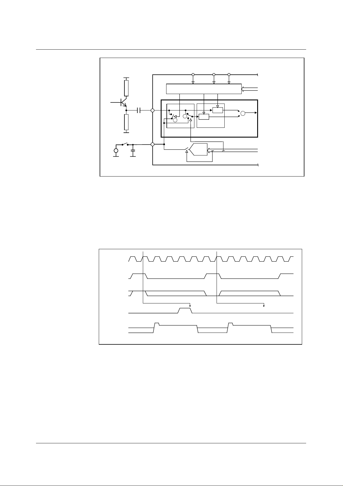
A typical input configurat ion is shown in Figure 5. A clam p pulse, CL, is generated from MCLK and
VSMP by the Timing Control B lock. When CL is ac tive the voltage on the WM8141 side of C
RINP, is forced to t he VRLC/VBIAS voltage (V
voltage at RINP initiall y remains at V
to video level) will couple through C
RLC is compatible with bot h CDS and non-CDS operating modes , as select ed by switch 2. Refer to
the CDS/non-CDS Processi ng section.
The RLC circuit clamps the
IN.
) by switch 1. When the CL pulse turns off, the
VRLC
but any subsequent variation in sensor voltage (from res et
VRLC
to RINP.
IN
, at
IN
WOLFSON MICROELECTRONICS LTD PD Rev 3.0 October 2000
11
Page 12
WM8141 Production Data
MCLK VSMP
TIMING CONTROL
R
S
S/H
CDS
4-BIT
RLC DAC
VRLCEXT
V
S/H
S
+
+
-
INPUT SAMPLING
BLOCK FOR RED
CHANNEL
FROM CONTROL
INTERFACE
TO OFFSET DAC
FROM CONTROL
INTERFACE
C
IN
EXTERNAL VRLC
VRLC/
VBIAS
RINP
RLC/ACYC
CL
2
1
RLC CDS
Figure 6 Reset Level Clamping and CDS Circuitry
If auto-cycling is not required, RLC can be s elected by pin RLC/ACYC. Figure 6 illus trates c ontrol of
RLC for a typical CCD waveform, with CL appli ed duri ng t he reset period.
The input signal applied to the RLC pin is sampled on t he positive edge of MCLK that occurs during
each VSMP pulse. The sampled level, high (or low) controls the presence (or absence) of t he internal
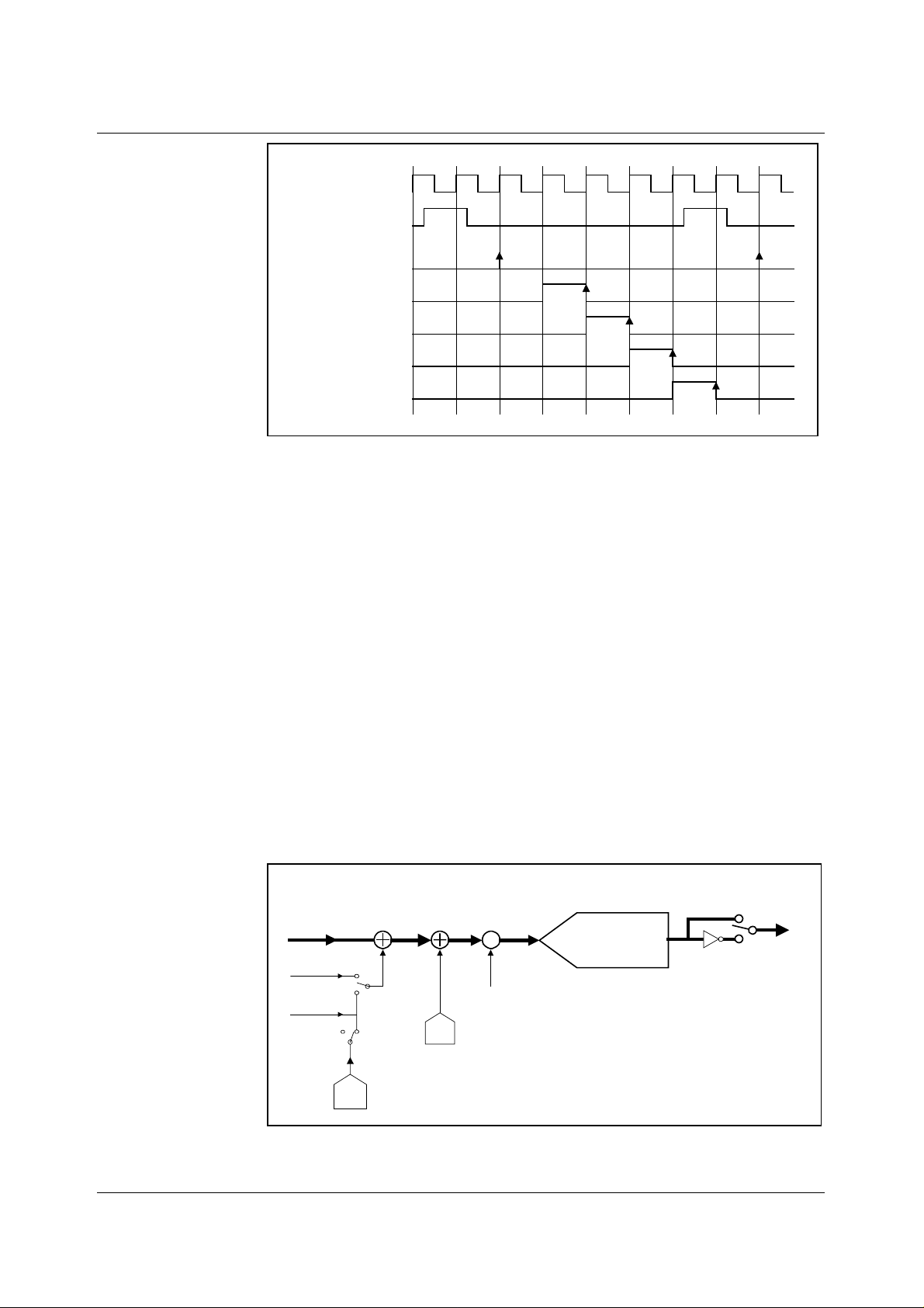
CL pulse on the next reset level. The position of CL can be adjusted by using control bits
CDSREF[1:0] (Figure 7).
If auto-cycling is required, pin RLC/ACYC is no longer available for this function and control bit
RLCINT determines whether clamping is applied.
MCLK
VSMP
RLC/ACYC
(CDSREF = 01)
INPUT VIDEO
Figure 7 Relationship of RLC Pin, MCLK and VSMP to Internal Clamp Pulse, CL
The VRLC/VBIAS pin can be dri ven internally by a 4-bit DAC (RLCDAC) by writing to cont rol bits
RLCV[3:0]. The RLCDAC range and step size may be increased by writing to control bit
RLCDACRNG. Alternatively, the VRLC/ VBIAS pin can be driven externally by writing to control bit
VRLCEXT to disable the RLCDAC and then applying a d.c. voltage to the pin.
CDS/NON-CDS PROCESSING
For CCD type input signals, the signal may be processed using CDS, which will remove pixel-by-pixel
common mode noi se. For CDS operation, the video level is processed with respect to the video reset
level, regardless of whether RLC has been performed. To sample using CDS , control bit CDS mus t
be set to 1 (default), this controls switch 2 (Figure 6) and caus es the signal reference to come from
the video reset level. The time at which the reset level is sampled, by clock R
programming control bits CDSREF[1:0], as s hown in Figure 8.
1X X0X X 0
Programmable Delay
CL
RGB RGB
No RLC on this PixelRLC on this Pixel
/CL, is adjustable by
s
RGB
WOLFSON MICROELECTRONICS LTD PD Rev 3.0 October 2000
12
Page 13
Production Data WM8141
MCLK
VSMP
VS
/CL (CDSREF = 00)
R
S
/CL (CDSREF = 01)
R
S
/CL (CDSREF = 10)
R
S
/CL (CDSREF = 11)
R
S
Figure 8 Reset Sample and Clamp Timing
For CIS type sensor signals , non-CDS process ing is used. I n this cas e, the video level is processed
with respect to the voltage on pin VRLC/VBIAS, generated internally or externally as described
above. The VRLC/VBIAS pin is s am pled by R
at the same tim e as Vs samples the video level in t his
s
mode.
OFFSET ADJUST AND PROGRAMMABLE GAIN
The output from the CDS bloc k is a dif ferential signal, which is added to the output of an 8-bit Off set
DAC to compensate for of fsets and then amplified by an 8-bit PGA . The gain and offset for each
channel are independently programmabl e by writi ng t o control bits DAC[7:0] and P GA[7:0].
In colour line-by-line mode the gai n and offset coeffici ents for each colour can be multiplexed i n order
(Red → Green → Blue → Red…) by pulsing the ACYC/RLC pin, or controlled via the FME,
ACYCNRLC and INTM[1:0] bits. Refer to the Line-by-line Operation sec tion for more details.
ADC INPUT BLACK LEVEL ADJUST
The output from the PGA must be offset to match the ful l -scale range of the ADC. For negative-going
input signals, a black level (zero differential) output from the PGA should be of fset to the top of the
ADC range. For positive going input signal the blac k level should be of fset to t he bottom of the ADC
range. This is achieved by writing to c ontrol bits PGAFS[1: 0] .
OVERALL SIGNAL FLOW SUMMARY
Figure 9 represents the processi ng of the video signal through the WM8141.
INPUT
SAMPLING
BLOCK
CDS = 1
RLC
DAC
+
RLCEXT=0
V
RLCSTEP
V
IN
V
RESET
V
VRLC
RLCEXT=1
CDS = 0
OFFSET DAC
V
1
-
*RLCV[3:0] + V
PGA
BLOCK
+
BLOCK
V
2
+
Offset
DAC
X
PGA gain
A = 208/(283-PGA[7:0])
260mV*(DAC[7:0]-127.5)/127.5
RLCBOT
OUTPUT
ADC BLOCK
V
3
analog
x (4095/VFS)
+0 if PGAFS[1:0]=11
+4095 if PGAFS[1:0]=10
+2047 if PGAFS[1:0]=0x
V
is RINP or GINP or BINP
IN
V
RESET
V
is voltage applied to VRLC pin
VRLC
CDS, RLCEXT,RLCV[3:0], DAC[7:0],
PGA[7:0], PGAFS[1:0] and INVOP are set
by programming internal control registers.
CDS=1 for CDS, 0 for non-CDS
is VIN sampled during reset clamp
INVERT
BLOCK
D
1
digital
D2 = D1 if INVOP = 0
D2 =4095-D1 if INVOP = 1
D
2
OP[11:0]
Figure 9 Overall Signal Flow
WOLFSON MICROELECTRONICS LTD PD Rev 3.0 October 2000
13
Page 14

WM8141 Production Data
The INPUT SAMPLING BLOCK produces an effective input voltage V
difference between the input video level V
difference between the input video level V
optionally set via the RLC DAC.
The OFFS ET DAC BLOCK then adds the amount of fine off set adjustment required to move the
black level of the input s i gnal towards 0V, producing V
The PGA BLOCK then amplifies the white level of the input signal to maximise the ADC range,
outputting voltage V
.
3
The ADC BLOCK then converts the analogue signal, V
The digital output is then invert ed, if required, through the OUTPUT INVER T B LOCK to produce D
CALCULATING OUTPUT FOR ANY GIVEN INPUT
The following equations describe the proc essing of the video and reset level signals through
the WM8141.
INPUT SAMPLING BLOCK: INPUT SAMPLING AND REFERENCING
If CDS = 1, (i.e. CDS operation) t he previously sampled reset level, V
input video.
V
=VIN - V
1
If CDS = 0, (non-CDS operation) the simultaneously sampled voltage on pin VRLC is subtracted
instead.
V
=VIN - V
1
................................................................... Eqn. 1
RESET
.................................................................... Eqn. 2
VRLC
. For CDS, this is the
and the input reset level V
IN
and the voltage on the VRLC/VBIAS pin, V
IN
.
2
, to a 12-bit unsigned digital out put, D1.
3
1
. For non-CDS this is the
RESET
, is subtracted from the
RESET
VRLC
,
2.
If RLCEXT = 1, V
If RLCEXT = 0, V
V
VRLC
V
is the step size of the RLC DAC and V
RLCSTEP
is an externally applied voltage on pin VRLC/VB I AS.
VRLC
is the output from the internal RLC DAC.
VRLC
=(V
∗ RLCV[3:0]) + V
RLCSTEP
................................. Eqn. 3
RLCBOT
is the minim um output of the RLC DAC.
RLCBOT
OFFSET DAC BLOCK: OFFSET (BLACK-LEVEL) ADJUST
The resultant signal V1 is added to the Offset DA C output.
V
= V1 + {260mV ∗ (DAC[7:0]-127.5) } / 27.5 ....................... Eqn. 4
2
PGA NODE: GAIN ADJUST
The signal is then mult i pl i ed by the PGA gain,
V
= V2 ∗ 208/(283- PGA[7:0]) .............................................. Eqn. 5
3
ADC BLOCK: ANALOGUE-DIGITAL CONVERSION
The analogue signal is then converted to a 12-bit unsigned number, with input range configured by
PGAFS[1:0].
D
[11:0] = INT{ (V3 /VFS) ∗ 4095} + 2047 PGAFS[1:0] = 00 or 01 ...... Eqn. 6
1
D
[11:0] = INT{ (V3 /VFS) ∗ 4095} PGAFS[1:0] = 11 ............... Eqn. 7
1
D
[11:0] = INT{ (V3 /VFS) ∗ 4095} + 4095 PGAFS[1:0] = 10 ............... Eqn. 8
1
where the ADC full-scale range, V
= 3V at AVDD=5V and VFS = 1.5V at AVDD=3.3V
FS
OUTPUT INVERT BLOCK: POLARITY ADJUST
The polarity of the digital output may be inverted by control bit INVOP.
D
[11:0] = D1[11:0] (INVOP = 0) ...................... Eqn. 9
2
D
[11:0] = 4095 – D1[11:0] (INVOP = 1) ...................... Eqn. 10
2
WOLFSON MICROELECTRONICS LTD PD Rev 3.0 October 2000
14
Page 15
Production Data WM8141
OUTPUT FORMATS
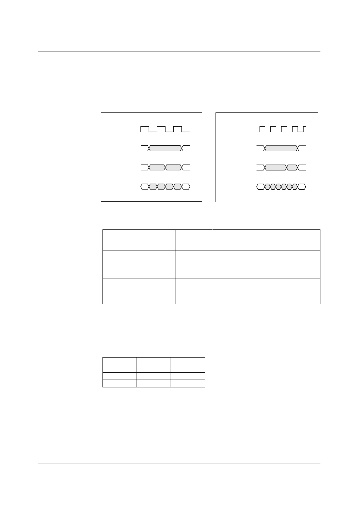
The digital data output from the ADC is availabl e to the user in eit her 12-bit parallel or 8/6/4-bit wide
multiplexed formats by s etting control bits MUXOP[1:0]. Latency of valid output data with respect to
VSMP is programmabl e by writi ng to control bits DEL[1:0]. The latency for each mode i s shown in the
Mode Timing Diagrams section.
Figure 10 shows the output data format s for Modes 1 – 2 and 4 – 6. Figure 11 shows the output data
formats for Mode 3. Table 1 summarises the output data obtained for each format .
MCLK
12-BIT PARALLEL
OUTPUT
8+4 AND 6+6-BIT
OUTPUT
4+4+4-BIT
OUTPUT
A
AB
ABCF
Figure 10 Output Data Formats
12-BIT PARALLEL
8+4 AND 6+6-BIT
Figure 11 Output Data Formats (Mode 3)
(Modes 1 − 2, 4 − 6)
OUTPUT
FORMAT
12-bit parallel 00 OP [ 11:0]
8+4-bit
multiplexed
6+6-bit
multiplexed
4+4+4-bit
multiplexed
(nibble)
MUXOP[1:0] OUTPUT
PINS
01 OP[11:4]
10 OP[11:4]
11 OP[11:8]
OUTPUT
A = d11, d10, d9, d8, d7, d6, d5, d4, d3, d2, d1, d0
A = d11, d10, d9, d8, d7, d6, d5, d4
B = d3, d2, d1, d0, PNS, CC[1], CC[0], OVRNG
A = d11, d10, d9, d8, d7, d6, CC[1] , CC[0]
B = d5, d4, d3, d2, d1, d0, PNS, OVRNG
A = d11, d10, d9, d8
B = d7, d6, d5, d4
C = d3, d2, d1, d0
F = PNS, CC[1], CC[0], OVRNG
Table 1 Details of Output Data Shown in Figures 9 and 10
MCLK
OUTPUT
OUTPUT
4+4+4-BIT
OUTPUT
A
AB
AB CFAB
FLAGS
The following flags are output during mul tiplexed modes:
PNS indicates whether the control i nterface is operating in parallel or s eri al , 1 = parallel, 0 = serial.
CC[1] and CC[0] indicate from which input the current output was s a mpled:
INPUT CC[1] CC[0]
RINP
GINP
BINP
Table 2 Input Sampled Flags CC[1:0]
OVRNG indicates that the c urrent output data was produced by an input signal that exceeded the
input range limit of the devi ce. 1 = out of range, 0 = within range.
WOLFSON MICROELECTRONICS LTD PD Rev 3.0 October 2000
00
01
10
15
Page 16
WM8141 Production Data
CONTROL INTERFACE
The internal control registers are programmable via the s erial or parallel digit al control int erface. The
register contents can also be read back via the parallel interface on OP[11:4], or via the serial
interface on pin OP[11]/S DO.
SERIAL INTERFACE: REGISTER WRITE
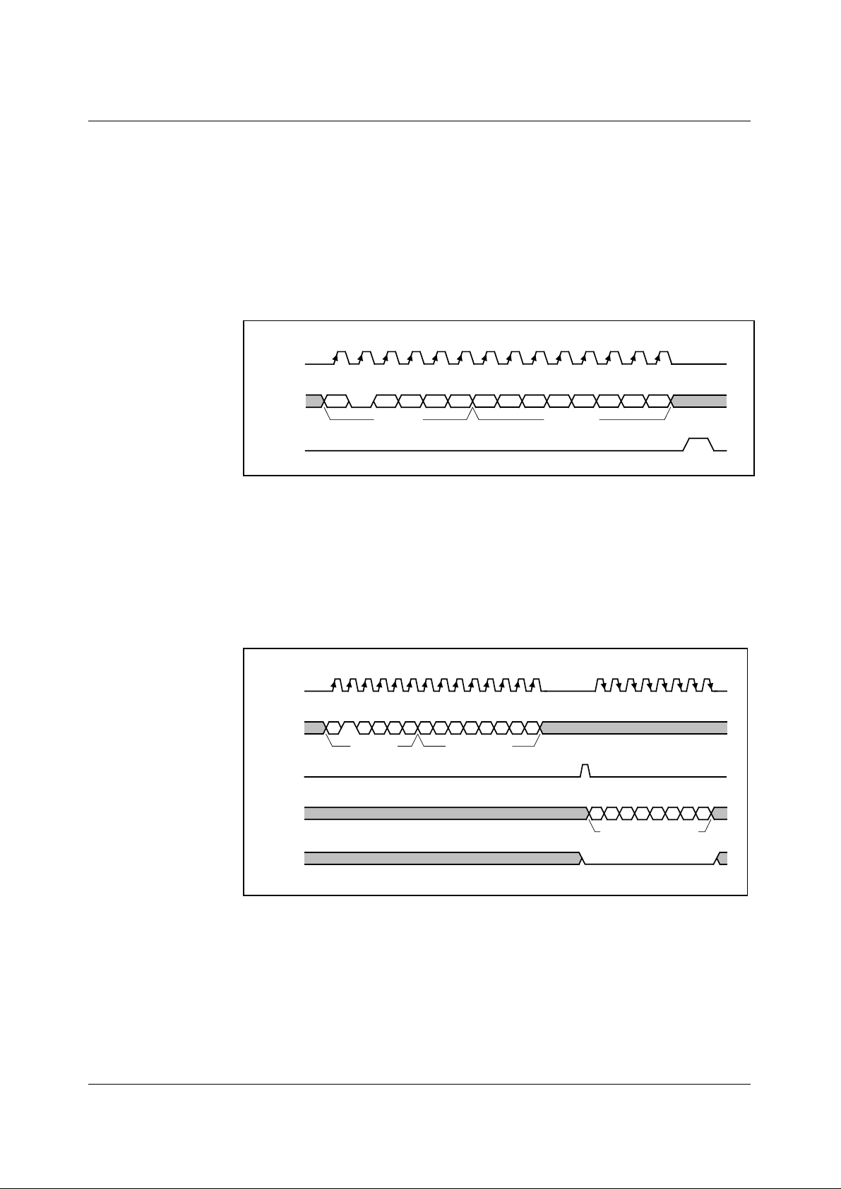
Figure 12 shows register writing in serial mode. Three pins , SCK, SDI and SEN are used. A s ix-bit
address (a5, 0, a3, a2, a1, a0) is c locked in through SDI, MSB first, fol lowed by an eight-bit data
word (b7, b6, b5, b4, b3, b2, b1, b0), also MSB first. Each bit i s latched on the rising edge of SCK.
When the data has been s hifted int o the devic e, a pulse is applied to S EN to t ransfer the dat a to the
appropriate internal register. Not e al l val i d regi sters have address bit a4 equal to 0 i n write mode.
SCK
SDI
SEN
Figure 12 Serial Interface Register Wri te
a5 0 a3a2a1a0b7b6b5b4b3b2b1b0
Address Data Word
SERIAL INTERFACE: REGISTER READ-BACK
Figure 13 shows register read-back in serial mode. Read-bac k is init iated by writing to the s erial bus
as described above but with address bit a4 set to 1, f ollowed by an 8-bit dummy dat a word. W riting
address (a5, 1, a3, a2, a1, a0) will cause the contents (d7, d6, d5, d4, d3, d2, d1, d0) of
corresponding register (a5, 0, a3, a2, a1, a0) to be output MSB fi rst on pin SDO (on the falling edge
of SCK). Note that pin SDO is shared with an output pin, OP[11], therefore OEB should always be
held low when register read-back data is expected on this pin. The next word m ay be read in to S DI
while the previous word is still being output on SDO.
SCK
SDI
SEN
SDO/
OP[11]
a51a3a2a1a0xxxxxxxx
Address Data Word
d7 d6 d5 d4 d3 d2 d1 d0
Output Data Word
OEB
Figure 13 Serial Interface Register Read-back
PARALLEL INTERFACE: REGISTER WRITE
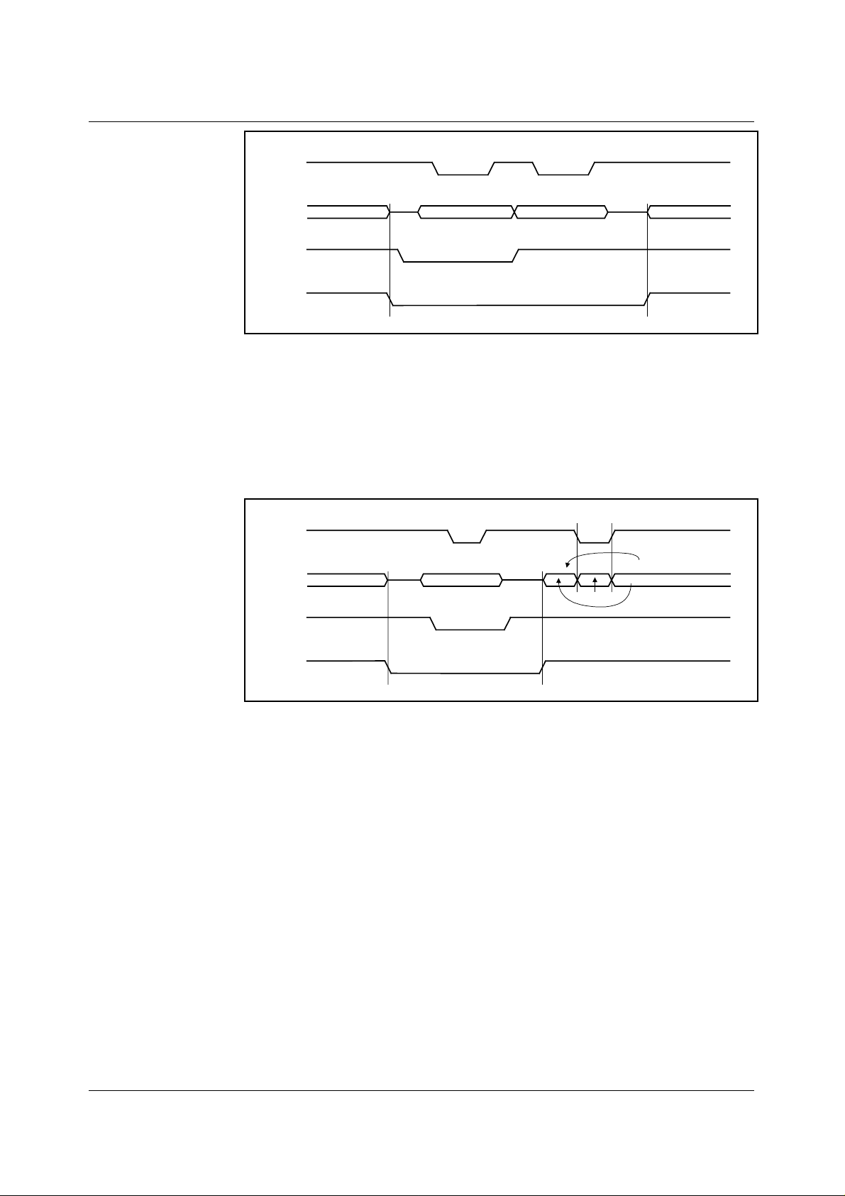
Figure 13 shows register write in parallel mode. The parallel interface uses bits OP[11:4] of the
output bus and the STB, DNA and RNW pins. P in RNW must be low during a write operation. The
DNA pin defines whether the data byte is addres s (low) or data (high). The 6-bit address (a5, 0, a3,
a2, a1, a0) is input into OP[9:4], LSB into OP[4], (OP[10] and OP[11] are ignored) when DNA is low,
then the 8-bit data word is input into OP[11:4], LSB int o OP[4], when DNA is high. The data bus
OP[11:4] for both address and data is clocked in on the falling edge of STB. Note all valid registers
have address bit a4 equal to 0.
WOLFSON MICROELECTRONICS LTD PD Rev 3.0 October 2000
16
Page 17
Production Data WM8141
STB
Driven Externally
Address Data
Driven by WM8141
Normal Output Data
OP[11:4]
Driven by WM8141
Normal Output Data
Hi-Z Hi-Z
DNA
RNW
Figure 14 Parallel Interface Register W rite
PARALLEL INTERFACE: REGISTER READ-BACK
Figure 15 shows register read-back in parallel mode. Read-back is initiated by writing the 6-bit
address (a5, 1, a3, a2, a1, a0) int o OP[9:4] by pulsing the STB pi n low. Note that a4 = 1 and pins
RNW and DNA are low. W hen RNW and DNA are high and ST B is strobed agai n, the contents (d7,
d6, d5, d4, d3, d2, d1, d0) of the corres ponding register (a5, 0, a3, a2, a1, a0) will be output on
OP[11:4], LSB on pin OP[ 4]. Until STB is pulsed low, the current c ontents of the ADC (shown as
Normal Output Data) will be present on OP[11:4]. Note that the register data becomes available on
the output data pins so OEB should be held low when read-back data is expected.
STB
Driven by WM8141
Normal Output Data
OP[11:4]
Driven by WM8141
Normal Output Data
Hi-Z
Driven Externally
Address
Hi-Z
Read Data
DNA
RNW
Figure 15 Parallel Interface Register Read-back
TIMING REQUIREMENTS
To use this device a master clock (MCLK) of up to 12MHz and a per-pixel synchronisation clock
(VSMP) of up to 6MHz are required. These clocks drive a timing control block, which produces
internal signals to cont rol the sampling of the video signal. MCLK to VSMP ratios and m aximum
sample rates for the vari ous modes are shown in Table 5.
PROGRAMMABLE VSMP DETECT CIRCUIT
The VSMP input is used to determine the sampling point and frequency of the WM8141. Under
normal operation a pulse of 1 MCLK period should be applied to VSMP at the desired sampling
frequency (as shown in the mode timi ng diagrams) and the input sample will be taken on the f irst
rising MCLK edge after VSMP has gone low. However, in certain appli cations s uch a signal m ay not
be readily available. The programmable VSMP detect circuit in the WM8141 allows the sampling
point to be derived from any signal of the correct frequency, s uch as a CCD s hift regis ter c loc k, when
applied to the VSMP pin.
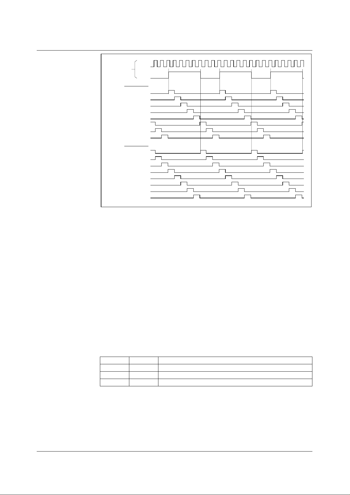
When enabled, by setting the VSMPDET control bit, the circuit detects either a risi ng or falling edge
(determined by POSNNEG cont rol bi t) on the VSMP input pin and generates an int ernal VSMP pulse.
This pulse can optionally be delayed by a number of MCLK periods, speci fied by the VDEL[ 2:0] bits.
Figure 16 shows the internal VSMP pulses that can be generated by this circuit for a typical clock
input signal. The internal VSMP pulse is then applied to the timing control block in place of the
normal VSMP pulse provided from the input pin. The sampling point then occurs on the first rising
MCLK edge after this internal VSMP pul se, as shown in the mode tim ing diagrams.
WOLFSON MICROELECTRONICS LTD PD Rev 3.0 October 2000
17
Page 18
WM8141 Production Data
REFERENCES
PINS
POSNNEG = 1
POSNNEG = 0
MCLK
VSMP
INPUT
(VDEL = 000) INTVSMP
(VDEL = 001) INTVSMP
(VDEL = 010) INTVSMP
(VDEL = 011) INTVSMP
(VDEL = 100) INTVSMP
(VDEL = 101) INTVSMP
(VDEL = 110) INTVSMP
(VDEL = 111) INTVSMP
(VDEL = 000) INTVSMP
(VDEL = 001) INTVSMP
(VDEL = 010) INTVSMP
(VDEL = 011) INTVSMP
(VDEL = 100) INTVSMP
(VDEL = 101) INTVSMP
(VDEL = 110) INTVSMP
(VDEL = 111) INTVSMP
Figure 16 Internal VSMP Pul ses Generated by Programmable VSMP Detect Circuit
The ADC reference voltages are derived from an internal bandgap reference, and buffered to pins
VRT and VRB, where they must be decoupl ed to ground. Pin VRX is driven by a s imilar buff er, and
also requires decoupling. The output buffer from the RLCDAC also requires decoupling at pin
VRLC/VBIAS
POWER SUPPLY
The WM8141 can run off either 3. 3V or 5V single supplies or from split 5V (core) and 3.3V (digit al
interface) supplies.
POWER MANAGEMENT
Power management for the devic e i s performed via the Control Interface. The device can be powered
on or off completely by the EN bit. Al ternat ively, when control bi t SE LPD i s high, only bl ocks selected
by further control bits (SELDIS[3:0]) are powered down. This allows the user to optimise power
dissipation in certain modes, or to define an intermediate standby mode t o allow a quicker recovery
into a fully active stat e. I n Line-by-li ne operation, the green and bl ue channel P GAs are aut om ati call y
powered down.
All the internal registers maintain their previous ly programmed value in power down modes and the
Control Interface inputs remain active. Table 3 summarises the power down control bit functions.
Table 3 Power Down Control
EN SELDPD
00
10
X1
Device completely powers down.
Device completely powers up.
Blocks with respective SELDIS[3:0] bit high are disabled.
WOLFSON MICROELECTRONICS LTD PD Rev 3.0 October 2000
18
Page 19
Production Data WM8141
LINE-BY-LINE OPERATION
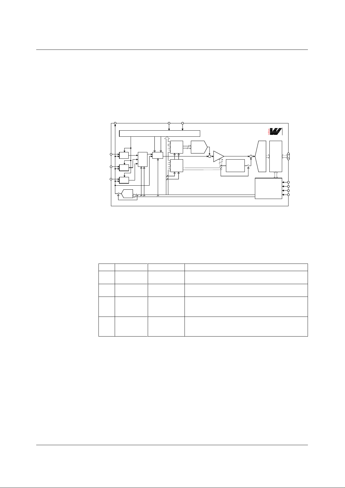
Certain linear sensors (e.g Contac t Image Sensors) give c olour output on a line-by-li ne basis. i.e a
full line of red pixels followed by a line of green pixels f ollowed by a line of blue pixels. In order to
accommodate t his type of signal the WM8141 can be set into Monochrome mode, with the input
channel switched by writing to control bits CHAN[ 1:0] between every line. Al ternatively, t he WM8141
can be placed into colour line-by-line mode by setting the LI NEBYLINE control bit. When this bit is
set the green and blue processing c hannels are powered down and the device i s forced internally to
only operate in MONO mode (because only one col our i s sampled at a tim e ) t hrough the red channel.
Figure 17 shows the signal path when operating in colour li ne-by-l i ne mode.
VSMP MCLKVRLC/VBIAS
TIMING CONTROLCL VSR
S
RINP
GINP
BINP
RLC
RLC
RLC
RLC
DAC
4
INPUT
MUX
CDS
R
G
B
R
G
B
OFFSET
MUX
PGA
MUX
8
OFFSET
DAC
Figure 17 Signal Path When in Line-by-Line Mode
PGA
+
8
I/P SIGNAL
POLARITY
ADJUST
+
WM8141
DATA
12-BIT
ADC
PORT
CONFIGURABLE
SERIAL/
PARALLEL
CONTROL
INTERFACE
I/O
OP[11:0]
SEN/STB
SCK/RNW
SDI/DNA
RLC/ACYC
In this mode the input m ultiplexer and (optionally) the P GA/Offset register m ultiplexers can be autocycled by the application of pulses to t he RLC/A CYC input pin by s ett ing the A CYCNRLC regi st er bit.
The multiplexers change on the firs t MCLK rising edge after RLC/ACY C is tak en high. Alt ernatively,
all three multiplexers can be controlled via the serial int erface by writing to regist er bits INTM[1:0] t o
select the desired colour. It is al so possible f or the input m ultiplexer to be cont rolled separat ely from
the PGA and Offset multiplexers. Table 4 describes all the multiplexer selection modes that are
possible.
FME ACYCNRLC NAME DESCRIPTION
00
01
10
Internal,
no force mux
Auto-cycling,
no force mux
Internal,
force mux
Input mux, offset and gain regi sters determined by
internal register bits INTM1, INTM0.
Input mux, offset and gain regi sters auto-cycled, RINP
→ GINP → BINP → RINP… on RLC/ACYC pulse.
Input mux selected from i nternal register bits FM1, FM0;
Offset and gain registers selected from internal regi ster
bits INTM1, INTM0.
11
Auto-cycling,
force mux
Input mux selected from i nternal register bits FM1, FM0;
Offset and gain registers auto-cycled, RINP → GINP →
BINP → RINP… on RLC/ACYC pulse.
Table 4 Colour Selection Description in Line-by-Line Mode
WOLFSON MICROELECTRONICS LTD PD Rev 3.0 October 2000
19
Page 20

WM8141 Production Data
OPERATING MODES
Table 5 summarises the m os t c om m only us ed m odes , t he cloc k waveform s required and t he regist er
contents required for CDS and non-CDS operat i on.
MODE DESCRIPTION CDS
Colour
1
Pixel-by-Pixel
Monochrome/
2
Colour
Line-by-Line
Fast
3
Monochrome/
Colour
Line-by-Line
Maximum
4
speed
Monochrome/
Colour
Line-by-Line
Slow Colour
5
Slow
6
Monochrome/
Colour
Line-by-Line
Table 5 WM8141 Operating Modes
AVAILABLE
Yes 2MSPS
Yes 2MSPS
Yes 4MSPS
Yes 1.5MSPS
Yes 1.5MSPS
MAX
SAMPLE
RATE
No 6MSPS
SENSOR
INTERFACE
DESCRIPTION
The 3 input channels
are sampled in
parallel. The signal is
then gain and offset
adjusted before being
multiplexed into a
single data stream
and converted by the
ADC, giving an output
data rate of 6MSPS
max.
As mode 1 except:
Only one input
channel at a time
is continuously
sampled.
Identical to mode 2 MCLK max
Identical to mode 2 MCLK max
Identical to mode 1 MCLK max
Identical to mode 2 MCLK max
TIMING
REQUIRE-
MENTS
MCLK max
MCLK:
VSMP
ratio is 6:1
MCLK max
MCLK:
VSMP
ratio is 6:1
MCLK:
VSMP
ratio is 3:1
MCLK:
VSMP
ratio is 2:1
MCLK:
VSMP
ratio is
2n:1, n ≥ 4
MCLK:
VSMP
ratio is
2n:1, n ≥ 4
REGISTER
CONTENTS
WITH CDS
SetReg1:
03(hex)
SetReg1:
07(hex)
Identical to
mode 2 plus
SetReg3:
bits 5:4 must
be set to
0(hex)
CDS not
possible
Identical to
mode 1
Identical to
mode 2
REGISTER
CONTENTS
WITHOUT
CDS
SetReg1:
01(hex)
SetReg1:
05(hex)
Identical to
mode 2
SetReg1:
45(hex)
Identical to
mode 1
Identical to
mode 2
Notes: 1. In Monochrome mode, SetReg3 bits 7:6 determine which input is to be sampled.
2. For Colour Line-by-Line, set control bit LINEBYLINE. For input selection, refer to Table 4, Colour Selection
Description in Line-by-Line Mode.
3. MCLK max = 12MHz at AVDD = 5V, MCLK max = 8MHz at AVDD = 3.3V.
WOLFSON MICROELECTRONICS LTD PD Rev 3.0 October 2000
20
Page 21
Production Data WM8141
OPERATING MODE TIMING DIAGRAMS
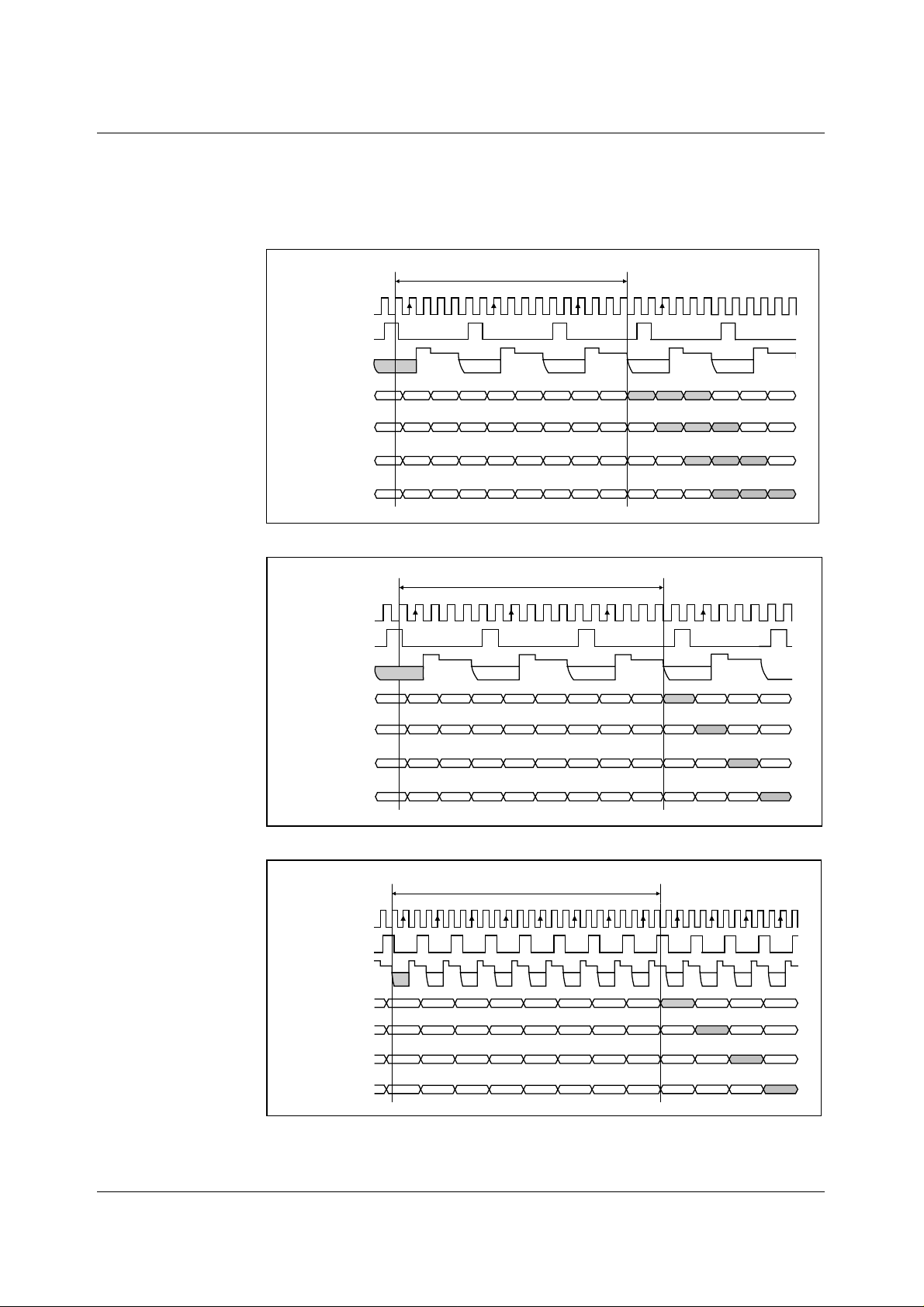
The following diagrams show 12-bit parallel format output and MCLK, VSMP and input video
requirements for operation of t he most comm only used modes as shown in Table 5. The diagrams
are identical for both CDS and non-CDS operat ion. Outputs from RINP, GINP and BINP are s hown
as R, G and B respectively. X denotes i nval id data.
16.5 MCLK PERIODS
MCLK
VSMP
INPUT VIDEO
OP[11:0] (DEL = 00)
OP[11:0] (DEL = 01)
OP[11:0] (DEL = 10)
OP[11:0] (DEL = 11)
G B R G B R G RB R BGR
R G B R G B R BG B GRB R
B R G B R G B GR G RBG B R
G B R G B R G RB R BGR G B
Figure 18 Mode 1 Operation
MCLK
VSMP
INPUT VIDEO
OP[11:0] (DEL = 00)
OP[11:0] (DEL = 01)
OP[11:0] (DEL = 10)
OP[11:0] (DEL = 11)
Figure 19 Mode 2 Operation
G B
G
16.5 MCLK PERIODS
X X R X X R X RX R XXR
R X X R X X R XX X XRX
X R X X R X X XR X RXX
X X R X X R X RX R XXR
23.5 MCLK PERIODS
MCLK
VSMP
INPUT VIDEO
OP[11:0] (DEL = 00)
OP[11:0] (DEL = 01)
OP[11:0] (DEL = 10)
OP[11:0] (DEL = 11)
R RR
RRRRRRR
R RR
RRRRRRR
R RR
RRRRRRR
R RR
RRRRRRR
R
R
R
R R
R
R
R
Figure 20 Mode 3 Operation
WOLFSON MICROELECTRONICS LTD PD Rev 3.0 October 2000
21
Page 22

WM8141 Production Data
16.5 MCLK PERIODS
MCLK
VSMP
INPUT VIDEO
R
OP[11:0] (DEL = 00)
OP[11:0] (DEL = 01)
OP[11:0] (DEL = 10)
OP[11:0] (DEL = 11)
R R
R R
R R
R R
Figure 21 Mode 4 Operation
MCLK
VSMP
INPUT VIDEO
OP[11:0] (DEL = 00)
R R R R R R R R
R
R R R R R R R R
R
R R R R R R R R
R
R R R R R R R R
16.5 MCLK PERIODS
G B R BGRG BRX X X
X
R R
R R
R
R R
R
R
G
OP[11:0] (DEL = 01)
OP[11:0] (DEL = 10)
OP[11:0] (DEL = 11)
R G X GRXR GXB B B
X R B RXBX RBG G G
B X G XBGB XGR R R
Figure 22 Mode 5 Operation (MCLK:VSMP Ratio = 8:1)
16.5 MCLK PERIODS
MCLK
VSMP
INPUT VIDEO
OP[11:0] (DEL = 00)
OP[11:0] (DEL = 01)
OP[11:0] (DEL = 10)
OP[11:0] (DEL = 11)
Figure 23 Mode 6 Operation (MCLK:VSMP Ratio = 8:1)
B
X
G B
R G B
RRRX X X X X X X X X
XXXX R X X R X X R X
XXXX X R X X R X X R
XXXR X X R X X R X X R
R
X
X
X
X
WOLFSON MICROELECTRONICS LTD PD Rev 3.0 October 2000
22
Page 23
Production Data WM8141
DEVICE CONFIGURATION
REGISTER MAP
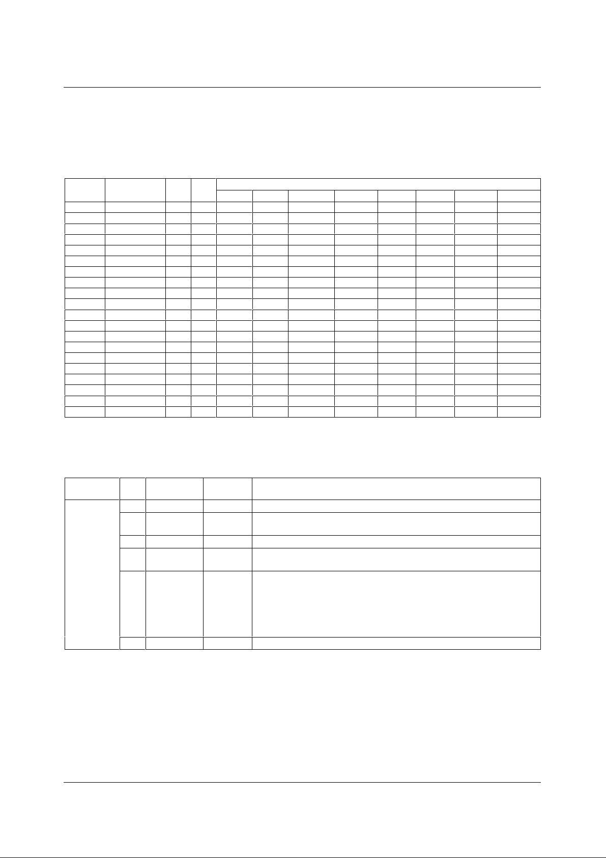
The following table describes the location of each cont rol bit used to determi ne the operation of the
WM8141. The register m ap is programm ed by writing (in serial or parallel ) the required codes t o the
appropriate addresses.
DESCRIPTION DEF
<a5:a0>
000001 Setup Reg 1 03 RW MODE4 PGAFS[1] PGAFS[0] SELPD MONO CDS EN
000010 Setup Reg 2 20 RW DEL[1] DEL[0] RLCDACRNG 0 VRLCEXT INVOP MUXOP[1] MUXOP[0]
000011 Setup Reg 3 1F RW CHAN[1] CHAN[0] CDSREF [1] CDSREF [0] RLCV[3] RLCV[2] RLCV[1] RLCV[0]
000100 Software Reset 00 W
000101 Auto-cycle Reset 00 W
000110 Setup Reg 4 00 RW FM[1] FM[0] INTM[1] INTM[0] RLCINT FME ACYCNRLC LINEBYLINE
000111 Revision Number 41 R
001000 Setup Reg 5 00 RW 0 0 0 POSNNEG VDEL[2] VDEL[1] VDEL[0] VSMPDET
001001 Setup Reg 6 00 RW 0 0 0 0 SELDIS[3] SELDIS [2] SELDIS[1] SELDIS[0]
001010 Reserved 00 RW 0 0 0 0 0 0 0 0
001011 Reserved 00 RW 0 0 0 0 0 0 0 0
001100 Reserved 00 RW 0 0 0 0 0 0 0 0
100000 DAC Value (Red) 80 RW DAC[7] DAC[6] DAC[5] DAC[4] DAC[3] DAC[2] DAC[1] DAC[0]
100001 DAC Value (Green) 80 RW DAC[7] DAC[6] DAC[5] DAC[4] DAC[3] DAC[2] DAC[1] DAC[0]
100010 DAC Value (Blue) 80 RW DAC[7] DAC[6] DAC[5] DAC[4] DAC[3] DAC[2] DAC[1] DAC[0]
100011 DAC Value (RGB) 80 W DAC[7] DAC[6] DAC[5] DAC[4] DAC[3] DAC[2] DAC[1] DAC[0]
101000 PGA Gain (Red) 00 RW PGA[7] PGA[6] PGA[5] PGA[4] PGA[3] PGA[2] PGA[1] PGA[0]
101001 PGA Gain (Green) 00 RW PGA[7] PGA[6] PGA[5] PGA[4] PGA[3] PGA[2] PGA[1] PGA[0]
101010 PGA Gain (Blue) 00 RW PGA[7] PGA[6] PGA[5] PGA[4] PGA[3] PGA[2] PGA[1] PGA[0]
101011 PGA Gain (RGB) 00 W PGA[7] PGA[6] PGA[5] PGA[4] PGA[3] PGA[2] PGA[1] PGA[0]
(hex)
RW
b7 b6 b5 b4 b3 b2 b1 b0
BITADDRESS
Table 6 Register Map
REGISTER MAP DESCRIPTION
The following table describes the function of each of the control bi ts shown in Table 6.
REGISTER BIT
NO
Setup
Register 1
0EN 1
1 CDS 1
2MONO 0
3 SELPD 0
5:4 PGAFS[1:0] 00
6MODE4 0
BIT
NAME(S)
DEFAULT DESCRIPTION
Global power down: 0 = complete power down, 1 = fully active.
Select correlated double sampling mode: 0 = single ended mode,
1 = CDS mode.
Mono/colour select: 0 = colour, 1 = monochrome operation.
Selective power down: 0 = no individual control,
1 = individual blocks can be disabled (controlled by SELDIS[3:0]).
Offsets PGA output to optimise the A DC range for different polarity sensor
output signals. Zero diff erential PGA input signal gives :
00 = Zero output
(use for bipolar video)
01 = Zero output
Required when operating in MODE4: 0 = other modes, 1 = MODE4.
10 = Full-scale positive output
(use for negative going video)
11 = Full-scale negative output
(use for positive going video)
WOLFSON MICROELECTRONICS LTD PD Rev 3.0 October 2000
23
Page 24

WM8141 Production Data
REGISTER BIT
Setup
Register 2
Setup
Register 3
Software
Reset
Auto-cycle
Reset
Setup
Register 4
WOLFSON MICROELECTRONICS LTD PD Rev 3.0 October 2000
NO
1:0 MUXOP[1:0] 0
2INVOP 0
3 VRLCEXT 0
5 RLCDACRNG 1
7:6 DEL[1:0] 00
3:0 RLCV[3:0] 1111
5:4 CDSREF[1:0] 01
7:6 CHAN[1:0] 00
0 LINEBYLINE 0
1 ACYCNRLC 0
2FME 0
3RLCINT 0
5:4 INTM[1:0] 00
7:6 FM[1:0] 00
BIT
NAME(S)
DEFAULT DESCRIPTION
Determines the output dat a format.
00 = 12-bit output
01 = 8-bit multiplexed (8+4 bits)
Digitally inverts the polari t y of output data.
0 = negative going video gives negative going output.
1 = negative-going video gives positive going out put data.
When set powers down the RLCDAC, c hangi ng i ts output to Hi-Z, allowing
VRLC to be externally driven.
Sets the output range of the RLCDA C.
0 = RLCDAC ranges from 0 to AVDD (approximately).
1 = RLCDAC ranges from 0 to VRT (approximat el y).
Sets the output latency in ADC clock periods.
1 ADC clock period = 2 MCLK periods except in mode 3 where 1 ADC clock
period = 3 MCLK periods.
00 = Minimum latency
01 = Delay by one ADC
clock period
Controls RLCDAC driving VRLC pin to defi ne single ended signal reference
voltage or Reset Level Clamp voltage. See Electrical Characteristics section
for ranges.
CDS mode reset timing adjust.
00 = Advance 1 MCLK period
01 = Normal
Monochrome mode channel select.
00 = Red channel select
01 = Green channel select
Any write to Software Reset causes all cells to be reset.
Any write to Auto-cycle Res et causes the auto-cycle c ounter to reset
to RINP.
Selects line by line operati on 0 = normal operation,
1 = line by line operation.
When line by line operati on i s selected MONO is forced t o 1 and CHA N[1:0]
to 00 internally, ensuring that t he correct internal tim i ng signals are
produced. Green and Blue PGAs are also disabled to save power.
When LINEBYLINE = 0 this bit has no ef f ec t.
When LINEBYLINE = 1 this bit determines the function of the RLC/ACYC
input pin and the input multiplexer and offset/gain register controls.
0 = RLC/ACYC pin enabled for Reset Level Clamp. Internal select i on of
input and gain/offset multiplexers.
1 = Auto-cycling enabled by pulsi ng t he RLC/ACYC input pin.
See Table 4, Colour Selection Description in Line-by-Line Mode for colour
selection mode detail s.
When auto-cycli ng i s enabled, the RLC/ACYC pin cannot be used for reset
level clamping. The RLCINT bi t may be used instead.
When LINEBYLINE = 0 this bit has no ef f ec t.
When LINEBYLINE = 1 this bit c ont rols the input force mux mode:
0 = No force mux, 1 = Force mux mode. Forc es the input mux to be selected
by FM[1:0] separately from gai n and of fset multiplexers.
See Table 4 for details.
When LINEBYLINE = 1 and ACYCNRLC = 1 this bit i s used to determine
whether Reset Level Clamping is us ed.
0 = RLC disabled, 1 = RLC enabled.
Colour selection bits us ed i n i nternal modes. See Table 4 for detai l s.
00 = Red, 01 = Green, 10 = Blue and 11 = Reserved.
Colour selection bits used in input force mux modes.
See Table 4 for details.
00 = Red, 01 = Green, 10 = Blue and 11 = Reserved.
10 = 6-bit multiplexed mode (6+6 bits)
11 = 4-bit multiplexed mode (4+4+4 bits)
10 = Delay by two ADC clock periods
11 = Delay by three ADC clock periods
10 = Retard 1 MCLK period
11 = Retard 2 MCLK periods
10 = Blue channel select
11 = Reserved
24
Page 25

Production Data WM8141
REGISTER BIT
Setup
Register 5
Setup
Register 6
Table 7 Register Control Bits
NO
0 VSMPDET 0
3:1 VDEL[2:0] 000
4 POSNNEG 0
3:0 SELDIS[3:0] 0
BIT
NAME(S)
DEFAULT DESCRIPTION
0 = Normal operation, signal on VSMP input pin is applied directly t o Timing
Control block.
1 = Programmable VSMP detect circuit is enabled. An internal
synchronisation pulse is generated from signal applied to VSMP input pin
and is applied to Timing Control bl ock.
When VSMPDET = 0 these bits have no effect.
When VSMPDET = 1 these bits set a programmable delay from the
detected edge of the signal applied to the VSMP pin. The internally
generated pulse is delayed by VDEL MCLK periods from the detected edge.
See Figure 16 Internal VSMP Pulses Generated by Programmable VSMP
Detect Circuit, for details.
When VSMPDET = 0 thi s bit has no effect.
When VSMPDET = 1 thi s bit controls whether positive or negat i ve edges
are detected:
0 = Negative edge on VSMP pin is detected and used to generate internal
timing pulse.
1 = Positive edge on VSMP pin is detected and used to generate internal
timing pulse.
See Figure 15 for further details.
Selective power disable register - activated when SELPD = 1.
Each bit disables respective function when 1, enabled when 0.
SELDIS[0] = Red CDS, PGA
SELDIS[1] = Green CDS, PG A
SELDIS[2] = Blue CDS, PGA
SELDIS[3] = ADC
WOLFSON MICROELECTRONICS LTD PD Rev 3.0 October 2000
25
Page 26

WM8141 Production Data
APPLICATIONS RECOMMENDATIONS
INTRODUCTION
The WM8141 is a mixed signal device, therefore careful PCB layout is required. The following
section contains PCB layout guidelines , which are recommended for optim al performance from the
WM8141, and some typical applications ci rcuits.
PCB LAYOUT
1) Use separate anal ogue and digital power and ground planes. The analogue and digit al ground
planes should be connected as close as possible to, or underneath, the WM8141.
2) Place all supply decoupling c apacitors as close as possible to t heir respecti ve supply pins and
provide a low impedance path from t he capacitors to the appropriate ground.
3) Avoid noise on AGND, pin 13.
4) Avoid noise on reference pins VRT, VRB and VRX. Place the decoupling capaci tors as close
as possible to these pins and provide a low impedance path from the capacitors to analogue
ground.
5) Input signals should be screened from eac h other and from other sources of noise to avoid
cross- talk and interf erence.
6) Minimise load capacitance on digital outputs. Capacitive loads of greater than 20pF will
degrade performance. Use buff ers if necessary and keep tracks short.
TYPICAL APPLICATIONS DIAGRAMS
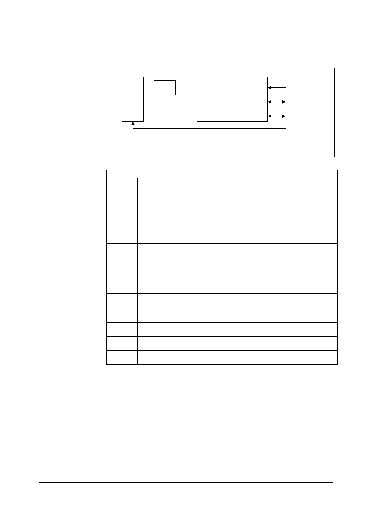
The WM8141 is intended to be us ed i n three types of architecture.
• Monochrome
• Colour Pixel-By-Pixel
• Colour Line-By-Line
Each of these architectures is outlined in this section.
The output from a CCD sensor usually has a high impedance and must therefore be buffered
as close to the sensor as possible. The sensor m anufacturers’ datasheets s pecify the buffer ci rcuit
to use.
Initially, the designer m ust decide if CDS and RLC are to be used. The WM8141 s upports both of
these functions and Wolfson recommend using both CDS and pixel-by-pixel RLC for optimal
performance. In this case a l ow value a.c. coupl ing capaci tor is requi red between the sensor and the
WM8141. Experiments have shown that a 100pF capac it or is t he opti m um value t o use, however this
may vary for particular applications depending on speed of operation and PCB l a yout .
WOLFSON MICROELECTRONICS LTD PD Rev 3.0 October 2000
26
Page 27
Production Data WM8141
MONOCHROME CCD
S
OUT
E
N
S
O
BUFFER
See sensor
datasheet for
details
R
SENSOR TIMING
Maximum pixel rate = 1.5Mpixels/second (Mode 6)
Maximum pixel rate = 2Mpixels/second (Mode 2)
Maximum pixel rate = 4Mpixels/second (Mode 3)
Maximum pixel rate = 6Mpixels/second (Mode 4)
C
RINP
WM8141
INCLUDING
RECOMMENDED
EXTERNAL
COMPONENTS
CLOCKSV
DATA
CONTROL I/F
SYSTEM
ASIC
Figure 24 Block Diagram of Monochrome CCD Application, AC Coupled
REGISTER SETTING
NOTE
NAME ADDRESS HEX BINARY
Set-up
register 1
000001 2F 0010 1111
EN = 1: Device enabled;
CDS = 1: CDS enabled;
MONO = 1: Monochrome operation;
SELPD = 1: Selective power down possible;
PGAFS[1:0] = 10: ADC range opt i mised for
negative going video;
MODE4 = 0: Only set when 2:1 MCLK:VSMP
ratio required (mode 4).
Set-up
register 2
000010 20 0010 0000
MUXOP[1:0] = 00: 12-bit parallel output;
INVOP = 0: Output data not invert ed;
VRLCEXT = 0: RLCDAC required to provide
reset level clamp voltage since sensor is
AC coupled;
RLCDACRNG = 1: RLCDAC range is 0V to V
DEL[1:0] = 00: Default latency.
Set-up
register 3
000011 1F 0001 1111
RLCV[3:0] = 1111: RLCDAC full scale voltage;
CDSREF[1:0] = 01: Default reset sample
position;
CHAN[1:0] = 00: Red channel sel ected.
Set-up
register 4
Set-up
register 5
Set-up
register 6
000101 00 0000 0000
001000 00 0000 0000
001001 06 0000 0110
Line-by-line mode not used so thi s register is
not required.
Only used if programmable V SMP circuit is
required.
SELDIS[3:0] = 0110: Disable green and blue
channels to reduce power.
Table 8 Typical Control Register Settings for Figure 24 (CDS, Neg ative-Going CCD
Video Signal, MCLK:V S MP = 2:1/3:1/6:1/ 8:1)
;
RT
WOLFSON MICROELECTRONICS LTD PD Rev 3.0 October 2000
27
Page 28
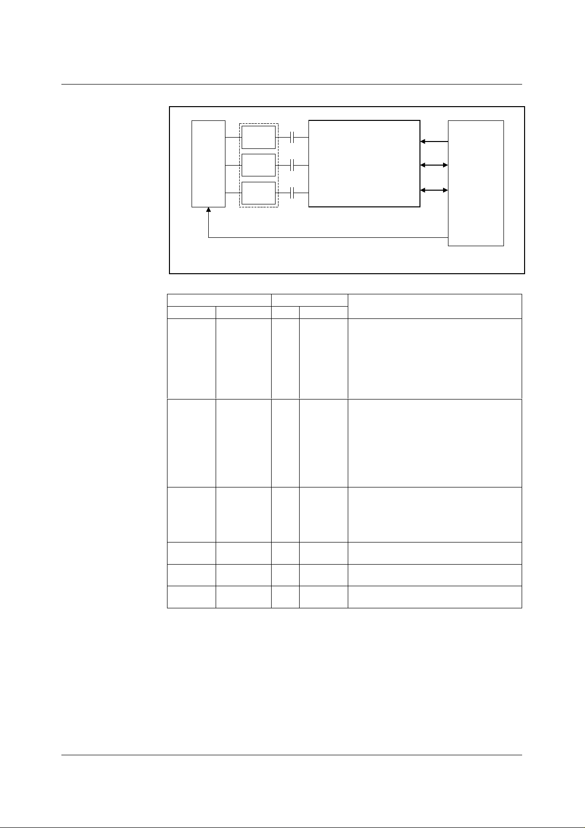
WM8141 Production Data
COLOUR PIXEL-BY-PIXEL
C
R
S
BUFFER
E
N
G
S
BUFFER
O
R
Maximum pixel rate = 1.5Mpixels/second (Mode 5)
Maximum pixel rate = 2Mpixels/second (Mode 1)
B
BUFFER
See sensor
datasheet for
details.
Figure 25 Block Diagram of Colour Pixel-By-Pixel Application, AC Coupled
R
RINP
C
G
GINP
C
B
BINP
WM8141
INCLUDING
RECOMMENDED
EXTERNAL
COMPONENTS
SENSOR TIMING
CLOCKS
DATA
CONTROL I/F
SYSTEM
ASIC
REGISTER SETTING
NOTE
NAME ADDRESS HEX BINARY
Set-up
register 1
000001 13 0010 0011
EN = 1: Device enabled;
CDS = 1: CDS enabled;
MONO = 0: Colour operation;
SELPD = 0: No selective power down;
PGAFS[1:0] = 10: ADC range opt imised for
negative going video;
MODE4 = 0: Not required for colour.
Set-up
register 2
000010 20 0010 0000
MUXOP[1:0] = 00: 12-bit parallel output;
INVOP = 0: Output data not invert ed;
VRLCEXT = 0: RLCDAC required to provide
reset level clamp voltage since sensor is
AC coupled;
RLCDACRNG = 1: RLCDAC range is 0V
to V
;
RT
DEL[1:0] = 00: Default lat ency
Set-up
register 3
000011 1F XX01 1111
RLCV[3:0] = 1111: RLCDAC full scale voltage;
CDSREF[1:0] = 01: Default reset sample
position;
CHAN[1:0] = XX: Colour mode so not
required.
Set-up
register 4
Set-up
register 5
Set-up
000101 00 0000 0000
001000 00 0000 0000
001001 00 0000 0000
Line-by-Line mode not used so this register is
not required.
Only used if programmable V SMP circuit is
required.
All channels enabled.
register 6
Table 9 Typical Control Register Settings for Figure 25 (CDS, Neg ative-Going CCD
Video Signal, MCLK:VSMP = 6:1/8:1)
WOLFSON MICROELECTRONICS LTD PD Rev 3.0 October 2000
28
Page 29
Production Data WM8141
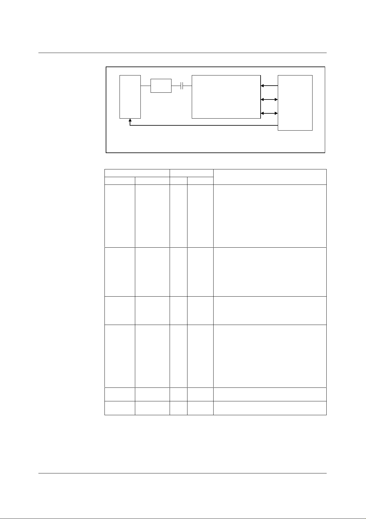
COLOUR LINE-BY-LINE
S
OUT
E
N
S
O
BUFFER
See sensor
datasheet for
details
R
SENSOR TIMING
Maximum pixel rate = 1.5Mpixels/second (Mode 6)
Maximum pixel rate = 2Mpixels/second (Mode 2)
Maximum pixel rate = 4Mpixels/second (Mode 3)
Maximum pixel rate = 6Mpixels/second (Mode 4)
C
RINP
WM8141
INCLUDING
RECOMMENDED
EXTERNAL
COMPONENTS
CLOCKSV
DATA
CONTROL I/F
SYSTEM
ASIC
Figure 26 Block Diagram Of Colour Line-By-Line Application, AC Coupled
REGISTER SETTING
NOTE
NAME ADDRESS HEX BINARY
Set-up
register 1
000001 23 0010 0X11
EN = 1: Device enabled;
CDS = 1: CDS enabled;
MONO = X: Forced internally when LINEBYLINE
is set;
SELPD = 0: No selective power down;
PGAFS[1:0] = 10: ADC range opt i mised for
negative going video;
MODE4 = 0: set high if MCLK:VSMP rat i o of 2:1
is required.
Set-up
register 2
000010 20 0010 0000
MUXOP[1:0] = 00: 12-bit parallel output;
INVOP = 0: Output data not invert ed;
VRLCEXT = 0: RLCDAC required to provide
reset level clamp voltage since sensor is
AC coupled;
RLCDACRNG = 1: RLCDAC range is 0V to V
DEL[1:0] = 00: Default latency.
Set-up
register 3
000011 1F 01 1111
RLCV[3:0] = 1111: RLCDAC full scale voltage;
CDSREF[1:0] = 01: Default reset sample
position;
CHAN[1:0] = XX: Colour mode so not required.
Set-up
register 4
000101 0B 00XX 1111
LINEBYLINE = 1: Line by line mode selected;
ACYCNRLC = 1: Auto-cycli ng requi red;
FME = 1: Input mux controlled by FME bits;
RLCINT = 1: RLC performed on every pixel;
INTM[1:0] = XX: PGA/Offset multiplexers
controlled by auto-cycling s o these bits have
no effect;
FME[1:0] = 00: Controls input multiplexer to
select red channel.
Set-up
register 5
Set-up
register 6
001000 00 0000 0000
001001 00 0000 0000
Only used if programmable V SMP circuit is
required.
Green and blue channels are automatically
powered down when LINEBYLINE = 1.
Table 10 Typical Control Register S etti n g s fo r F igure 26 (CDS, Negative-Going CCD
Video Signal, MCLK/VS MP = 2:1/3:1/6:1/ 8:1)
;
RT
WOLFSON MICROELECTRONICS LTD PD Rev 3.0 October 2000
29
Page 30
WM8141 Production Data
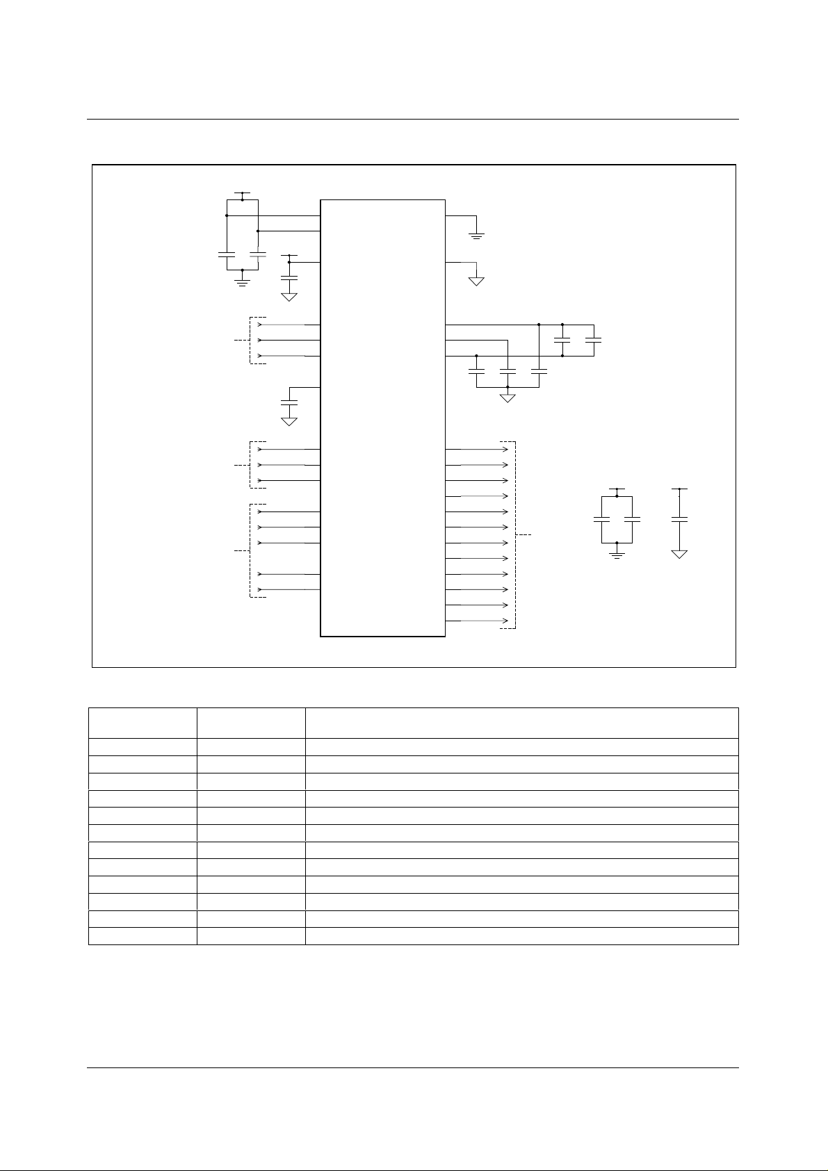
RECOMMENDED EXTERNAL COMPONENTS
DVDD
C2C1
DGND
Video
Inputs
Timing
Signals
Interface
Controls
1.
C1-9 should be fitted as close toNOTES:
WM8141 as possible.
AGND and DGND should be connected
2.
as close to WM8141 as possible.
AVDD
AGND
AGND
C3
C9
14
DVDD1
32
DVDD2
12
AVDD
21
RINP
20
GINP
19
BINP
18
VRLC/VBIAS
28
MCLK
27
VSMP
26
RLC/ACYC
25
SCK/RNW
24
SDI/DNA
23
SEN/STB
22
OEB
11
NRESET
WM8141
OP[11]/SDO
DGND
AGND
VRT
VRX
VRB
OP[10]
OP[9]
OP[8]
OP[7]
OP[6]
OP[5]
OP[4]
OP[3]
OP[2]
OP[1]
OP[0]
29
13
AGND
16
17
15
10
9
8
7
6
5
4
3
2
1
31
30
C6 C8
C7
AGND
Output
Data
Bus
C4 C5
DVDD
++ +
DGND AGND
AVDD
C11C10
C12
Figure 27 External Components Diagram
COMPONENT
REFERENCE
C1 100nF
C2 100nF
C3 100nF
C4 10nF
C5 1µF
C6 100nF
C7 100nF
C8 100nF
C9 100nF
C10 10µF
C11 10µF
C12 10µF
SUGGESTED
VALUE
DESCRIPTION
De-coupling for DVDD1.
De-coupling for DVDD2.
De-coupling for AVDD.
High frequency de-coupling between VRT and VRB.
Low frequency de-coupling between VRT and VRB (non-polarised).
De-coupling for VRB.
De-coupling for VRX.
De-coupling for VRT.
De-coupling for VRLC.
Reservoir capacitor for DVDD.
Reservoir capacitor for DVDD.
Reservoir capacitor for AVDD.
Table 11 External Components Descriptions
WOLFSON MICROELECTRONICS LTD PD Rev 3.0 October 2000
30
Page 31
Production Data WM8141
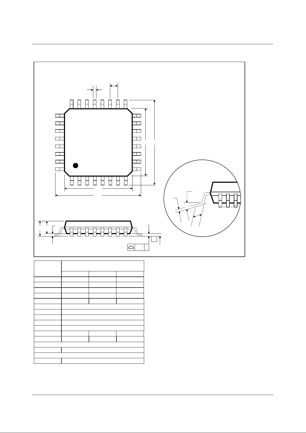
PACKAGE DIMENSIONS
FT: 32 PIN TQFP (7 x 7 x 1.4 mm)
b
24
32
D1
D
DM002.B
e
17
1625
E1 E
9
81
Θ
c
A2
A1
ccc
-C-
SEATING PLANE
C
A
Dimensions
Symbols
(mm)
MIN NOM MAX
A
A
1
A
2
b
c
D
D
1
E
E
1
e
L
Θ
----- ----- 1.60
0.05 ----- 0.15
1.35 1.40 1.45
0.30 0.37 0.45
0.09 ----- 0.20
9.00 BSC
7.00 BSC
9.00 BSC
7.00 BSC
0.80 BSC
0.45 0.60 0.75
o
0
3.5
o
o
7
Tolerances of Form and Position
ccc
REF:
NOTES:
A. ALL LINEAR DIMENSIONS ARE IN MILLIMETERS.
B. THIS DRAWING IS SUBJECT TO CHANGE WITHOUT NOTICE.
C. BODY DIMENSIONS DO NOT INCLUDE MOLD FLASH OR PROTRUSION, NOT TO EXCEED 0.25MM.
D. MEETS JEDEC.95 MS-026, VARIATION = BBA. REFER TO THIS SPECIFICATION FOR FURTHER DETAILS.
0.10
JEDEC.95, MS-026
L
WOLFSON MICROELECTRONICS LTD PD Rev 3.0 October 2000
31
 Loading...