

Page 1
WM2618
Dual 12-bit Serial Input Voltage Output DAC
Production Data, October 2000, Rev 1.1
FEATURES
• Two 12-bit voltage output DACs
• Single supply from 2.7V to 5.5V supply operation
• DNL ±0.5 LSB, INL ±1.9
• Low power consumption
- 3mW typical in slow mode
- 8mW typical in fast mode
• TMS320, (Q)SPI, and Microwire compatible
serial interface
• Programmable settling time 4µs or 12µs typical
APPLICATIONS
• Battery powered test instruments
• Digital offset and gain adjustment
• Battery operated/remote industrial controls
• Machine and motion control devices
• Cellular telephones
• Wireless telephone and communication systems
• Speech synthesis
• Arbitrary waveform generation
ORDERING INFORMATION
DEVICE TEMP. RANGE PACKAGE
WM2618CD 0° to 70°C 8-pin SOIC
WM2618ID -40° to 85°C 8-pin SOIC
DESCRIPTION
The WM2618 is a dual 12-bit voltage output, resistor string,
digital-to-analogue converter. A power-on-reset function
ensures repeatable start-up condi tions.
The device has been designed to interface effi ciently t o industry
standard microprocessors and DSPs, including the TMS320
family. The W M2618 is programmed with a 16-bit serial word.
The WM2618 has a sim ple-to-use single 2.7V to 5.5V s upply.
The digital inputs feature Schmitt triggers for high noise
immunity.
The number of clocks from the falling edge of NCS are counted
automatically. The device is then updated and disabled from
accepting further data inputs.
Excellent performance is delivered with a typical DNL of ±0.5
LSBs. The settling t ime of the DAC is programmable to al low
the designer to optimise speed versus power dissipation.
The device is available in an 8-pin SOIC package ideal for
space-critical applications. Commercial temperature (0° to
70°C) and Industrial temperature (-40° to 85°C) variants are
supported.
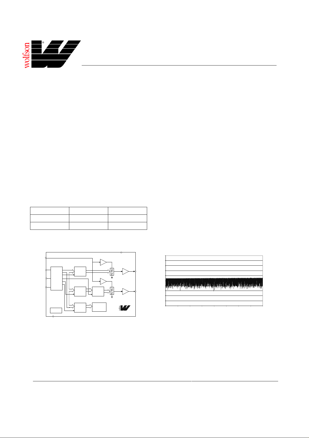
BLOCK DIAGRAM TYPICAL PERFORMANCE
VDD
(8)
REFIN(6)
DIN (1)
SCLK (2)
NCS (3)
16-BIT
SHIFT
REGISTER
AND
CONTROL
LOGIC
POWER-ON
RESET
(5)
AGND
12-BIT
data
DAC A
LATCH
12-BIT
DAC B
HOLDING
LATCH
2-BIT
CONTROL
LATCH
REFERENCE
INPUT BUFFER
REFERENCE
INPUT BUFFER
12-BIT
DAC B
CONTROL
LATCH
POWERDOWN/
SPEED
CONTROL
X1
X1
DAC
OUTPUT
BUFFER
X2
DAC
OUTPUT
BUFFER
X2
WM2618
WOLFSON MICROELECTRONICS LTD
Lutton Court, Bernard Terrace, Edi nburgh, EH8 9NX, UK
Tel: +44 (0) 131 667 9386
Fax: +44 (0) 131 667 5176
Email: [email protected]
http://www.wolfson.co.uk
(4) OUTA
(7) OUTB
1
5V = VDD, V
= 2.048V, Speed = Fast mode, Load = 10k/10 0pF
0.8
0.6
0.4
0.2
0
DNL - LSB
-0.2
-0.4
-0.6
-0.8
-1
0 512 1024 1536 2048 2559 3071 3583 4095
REF
DIGITAL CODE
Production Data datasheets contain final
specifications current on publication date.
Supply of products conforms to Wol fson
Microelectronics’ Term s and Conditions.
2000 Wolfson Microelectronics Ltd.
Page 2
WM2618 Production Data PIN CONFIGURATION
DIN
SCLK
NCS
OUTA
1
2
3
4
VDD
8
OUTB
7
REFIN
6
AGND
5
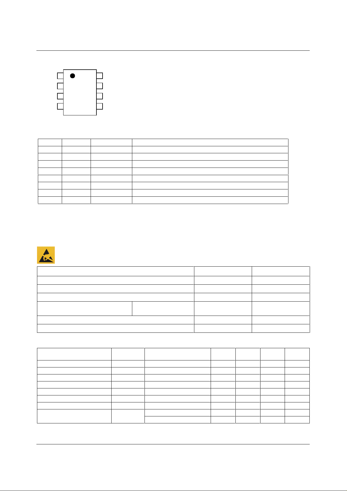
PIN DESCRIPTION
PIN NO NAME TYPE DESCRIPTION
1
2
3
4
5
6
7
8
DIN Digital input Serial dat a i nput.
SCLK Digital input Serial clock input.
NCS Digital input Chip select. This pin is active low.
OUTA Analogue output DAC A analogue output.
AGND Supply Analogue ground.
REFIN Analogue input Voltage reference input.
OUTB Analogue output DAC B analogue output
VDD Supply Positive power supply.
ABSOLUTE MAXIMUM RATINGS
Absolute Maximum Ratings are s tres s rat ings only. P erm anent damage to the device may be c aused by c onti nuously operat ing at
or beyond these limits. Device functional operating lim its and guaranteed performance s pecifications are gi ven under Electrical
Characteristics at the test conditions s pecified
ESD Sensitive Device. Thi s device i s m anufactured on a CMOS process . It i s t herefore generi cally suscept ible
to damage from excessi ve stati c voltages . Proper ES D precautions mus t be tak en during handling and st orage
of this device.
CONDITION MIN MAX
Supply voltage, VDD to AGND
Digital input voltage
Reference input voltage
Operating temperature range, T
Storage temperature
Lead temperature 1.6mm (1/16 inch) soldering for 10 sec onds
A
WM2618C
WM2618I
-0.3V VDD + 0.3V
-0.3V VDD + 0.3V
0°C
-40°C
-65°C 150°C
7V
70°C
85°C
260°C
RECOMMENDED OPERATING CONDITIONS
PARAMETER SYMBOL TEST CONDITIONS MIN TYP MAX UNIT
Supply voltage
High-level digital input voltage
Low-level digital input voltage
Reference voltage to REFIN
Load resistance
Load capacitance
Serial clock rate
Operating free-air temperature
Note: Reference voltages greater than VDD/ 2 will caus e saturation for large DAC codes.
WOLFSON MICROELECTRONICS LTD PD Rev 1.1 October 2000
VDD 2.7 5.5 V
V
IH
V
IL
V
REF
R
L
C
L
fSCLK 20
T
A
WM2618C 0 70 °C
WM2618I -40 85 °C
2V
0.8 V
VDD - 1.5 V
2kΩ
100
2
Page 3
Production Data WM2618
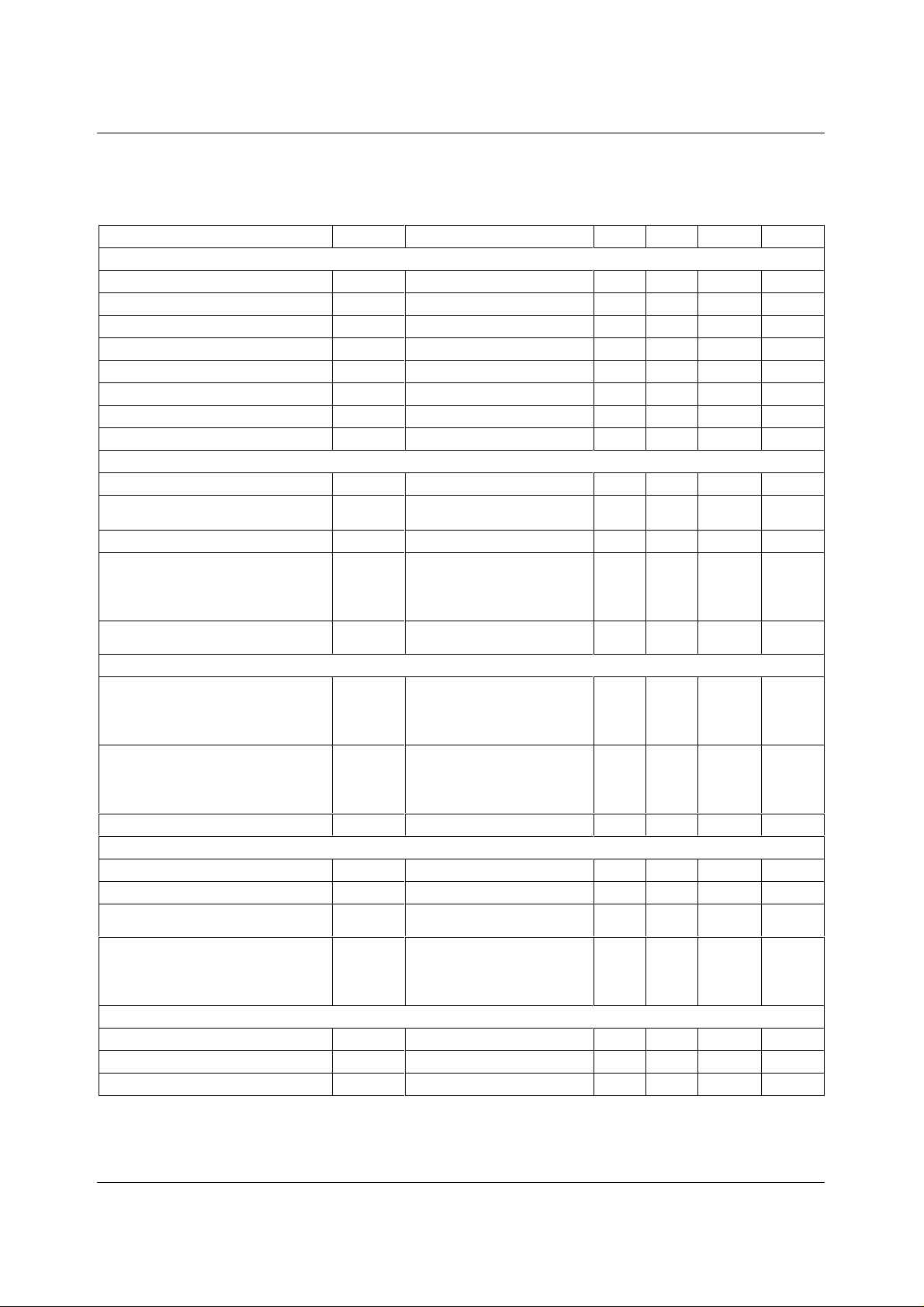
ELECTRICAL CHARACTERISTICS
Test Conditions:
= 10kΩ, CL = 100pF. VDD = 5V ± 10%, V
R
L
free-air temperature range (unless noted otherwise)
PARAMETER SYMBOL TEST CONDITIONS MIN TYP MAX UNIT
Static DAC Specifications
Resolution
Integral non-linearity
Differential non-linearity
Zero code error
Gain error
D.c. power supply rejection rati o
Zero code error temperature coeffi cient
Gain error temperature coefficient
DAC Output Specifications
Output voltage range
Output load regulation
Power Supplies
Active supply current
Power down supply current
Dynamic DAC Specifications
Slew rate
Settling time
Glitch energy
Reference
Reference input resistanc e
Reference input capacitanc e
Reference feedthrough
Reference input bandwidth
Digital Inputs
High level input current
Low level input current
Input capacitance
= 2.048V and VDD = 3V ± 10%, V
REF
= 1.024V over recommended operati ng
REF
12 bits
INL See Note 1
DNL See Note 2
±1.9 ±4
±0.5 ±1
ZCE See Note 3 3
GE See Note 4 0.1
±12
±0.6
LSB
LSB
mV
% FSR
DC PSRR See Note 5 0.5 mV/V
See Note 6 10 ppm/°C
See Note 6 10 ppm/°C
0 VDD - 0.1 V
2kΩ to 10kΩ load
0.1 0.3 %
See Note 7
I
DD
No load, V
VDD = 5.5V, V
= 5.5V, V
VDD
= VDD, V
IH
= 2.048V Slow
REF
= 2.048V Fast
REF
IL
= 0V
0.6
1.6
1.0
2.5
mA
mA
See Note 8
No load,
0.01 µA
all digital inputs 0V or VDD
AC code 128 to 4095, 10%-90%
Slow
Fast
0.3
2.4
0.5
3.0
V/µs
V/µs
See Note 9
DAC code 128 to 4095
Slow
Fast
12.0
4.0
µs
µs
See Note 10
Code 2047 to 2048 10 nV-s
R
C
REFIN
REFIN
V
= 1VPP at 1kHz
REF
10 MΩ
5pF
-60 dB
+ 1.024V dc, DAC code 0
V
= 0.2VPP + 1.024V dc
REF
DAC code 2048
Slow
Fast
I
IH
I
IL
C
I
Input voltage = VDD 1 µA
Input voltage = 0V -1 µA
0.5
1.0
MHz
MHz
8pF
WOLFSON MICROELECTRONICS LTD PD Rev 1.1 October 2000
3
Page 4
WM2618 Production Data
Notes:
1. Integral non-linearity (INL) is the maximum deviation of the out put from the line between zero and full sc al e
(excluding the effects of zero code and full scale errors).
2. Differential non-linearity (DNL) is the difference between the measured and ideal 1LSB ampl i t ude change of any
adjacent two codes. A guarantee of monotonicity means the output voltage changes in the s ame direction (or
remains constant) as a change in digital input code.
3. Zero code error is the voltage output when the DAC i nput code is zero.
4. Gain error is the deviation from the ideal f ul l scale output excluding the effec ts of zero code error.
5. Power supply rejection ratio is measured by varying VDD from 4. 5V to 5.5V and measuring the proporti on of this
signal imposed on the zero c ode error and t he gai n error.
6. Zero code error and Gain error temperature coefficients are normalised to full scale voltage.
7. Output load regulation is the difference between the output vol tage at full scale with a 10kΩ load and 2kΩ load. It
is expressed as a percentage of the ful l scale output voltage with a 10kΩ l oad.
8. I
9. Slew rate results are for the lower value of the rising and falling edge slew rates.
10. Settling time is the ti me taken for the signal t o settle to within 0.5LSB of t he final measured value for both ris i ng
SERIAL INTERFACE
is measured while continuous l y writing code 2048 to the DAC. For VIH < VDD - 0.7V and VIL > 0.7V supply
DD
current will increase.
and falling edges. Limits are ens ured by des ign and characterisation, but are not produc t i on tested.
t
SUCSS
NCS
t
WCLtWCH
t
SUCS1
t
SUCS2
SCLK
DIN
t
SUDCLK
D15 D14 D13 D12 D11 D0
t
HDCLK
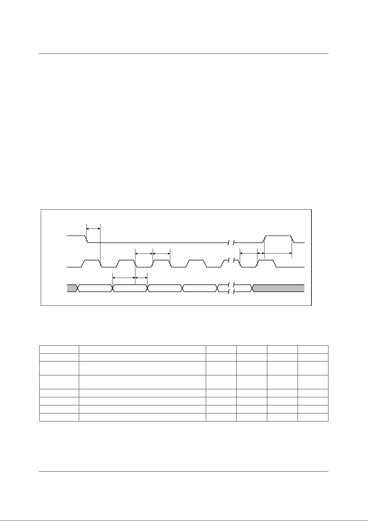
Figure 1 Timing Diagram
Test Conditions:
R
= 10kΩ, CL = 100pF. VDD = 5V ± 10%, V
L
= 2.048V and VDD = 3V ± 10%, V
REF
= 1.024V over recommended
REF
operating free-air temperature range (unless noted otherwise)
SYMBOL TEST CONDITIONS MIN TYP MAX UNIT
t
SUCSS
t
SUSCS1
t
SUSCS2
t
WCL
t
WCH
t
SUDCLK
t
HDCLK
Setup time NCS low before SCLK l o w
Setup time, fall i ng edge of SCLK to rising edge of
NCS, external end of write
Setup time, rising edge of SCLK to falling edge of
NCS, start of next write cycle
Pulse duration, SCLK high
Pulse duration, SCLK low
Setup time, data ready before SCLK falling edge
Hold time, data held valid after SCLK falling edge
5ns
10 ns
5ns
25 ns
25 ns
5ns
5ns
WOLFSON MICROELECTRONICS LTD PD Rev 1.1 October 2000
4
Page 5
Production Data WM2618
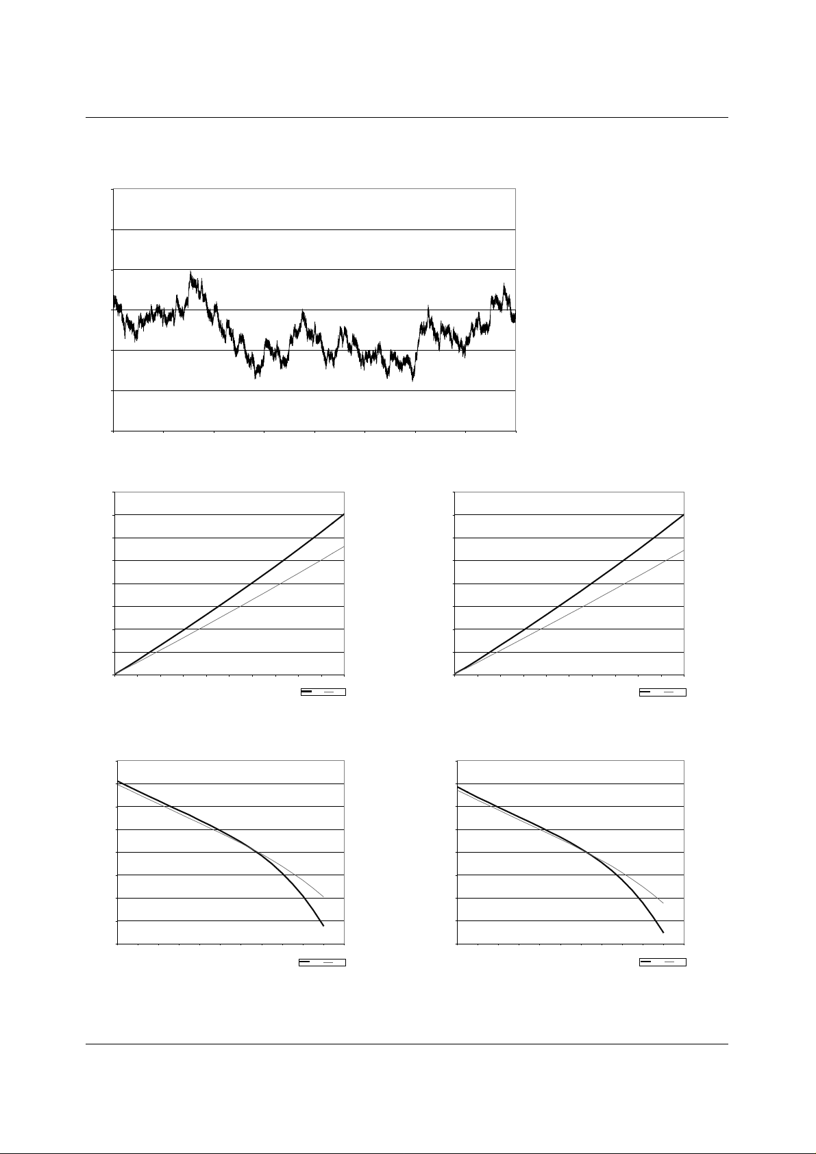
TYPICAL PERFORMANCE GRAPHS
3
5V = VDD, V
2
1
0
INL - LSB
-1
-2
-3
0 512 1024 1536 2048 2559 3071 3583 4095
Figure 2 Integral Non-Linearity
0.4
VDD = 3V, V
0.35
0.3
0.25
0.2
0.15
OUTPUT VOLTAGE - V
0.1
0.05
0
REF
012345678910
= 2.048V, Speed = Fast mode, Load = 10k/100pF
REF
= 1V, Input Code = 0
ISINK- mA
DIGITAL CO DE
Slow Fast
0.4
VDD = 5V, V
0.35
0.3
0.25
0.2
0.15
OUTPUT VOLTAGE - V
0.1
0.05
0
012345678910
= 2V, Input Code = 0
REF
ISINK - mA
Slow Fast
Figure 3 Sink Current VDD = 3V Figure 4 Sink Current VDD = 5V
2.06
VDD = 3V, V
2.055
2.05
2.045
2.04
2.035
OUTPUT VOLTAGE - V
2.03
2.025
2.02
01234567891011
= 1V, Input Code = 4095
REF
ISOURCE- mA
Slow Fast
4.1
VDD = 5V, V
4.095
4.09
4.085
4.08
4.075
OUTPUT VOLTAGE - V
4.07
4.065
4.06
01234567891011
= 2V, Input Code = 4095
REF
ISOURCE - mA
Slow Fast
Figure 5 Source Current VDD = 3V Figure 6 Source Current VDD = 5V
WOLFSON MICROELECTRONICS LTD PD Rev 1.1 October 2000
5
Page 6
WM2618 Production Data DEVICE DESCRIPTION
GENERAL FUNCTION
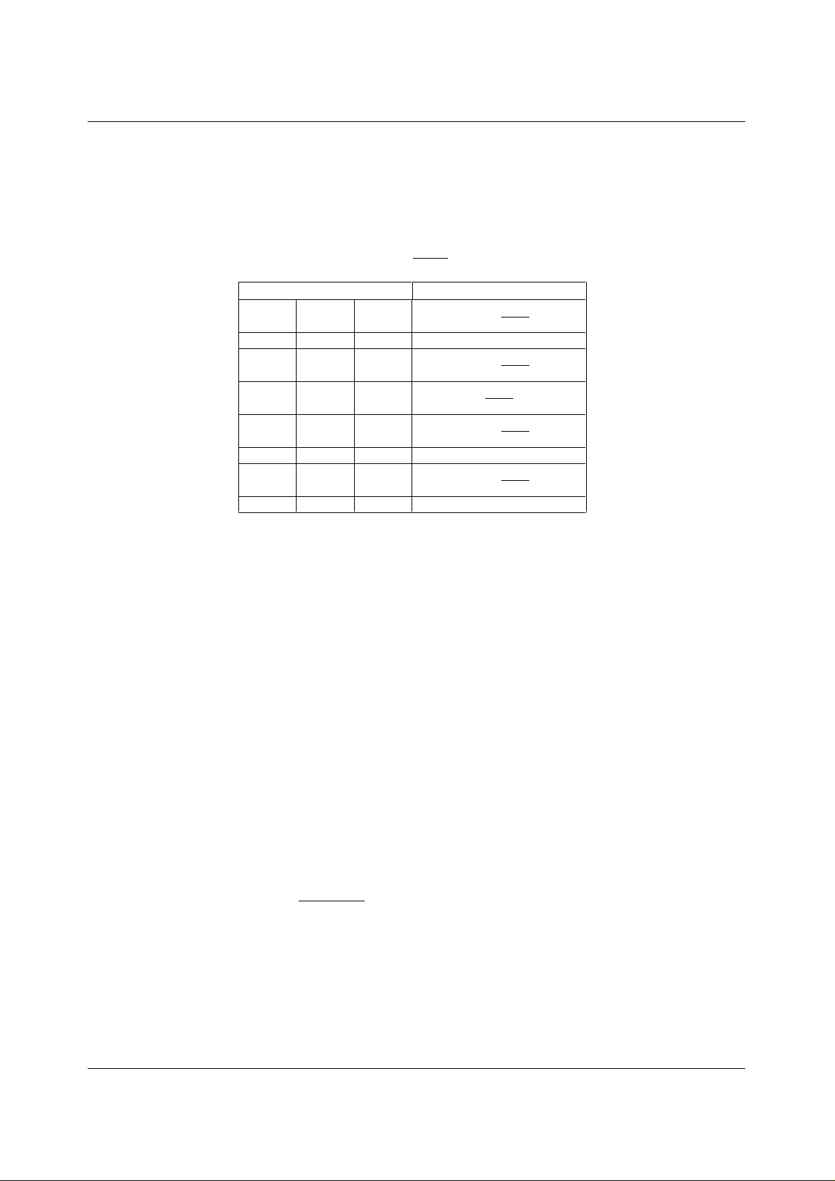
The device uses a resistor st ring network buffered with an op amp to convert 12-bit digital
data to analogue voltage levels (see B l ock Diagram). The output volt age i s determined by t he
reference input voltage and the input c ode according to the following relationship:
CODE
()
Output voltage =
INPUT OUTPUT
1111 1111 1111
::
1000 0000 0001
1000 0000 0000
0111 1111 1111
::
0000 0000 0001
0000 0000 0000 0V
Table 1 Binary Code Table (0V to 2V
REF
V2
4096
4095
()
REF
V2
4096
2049
()
REF
V2
4096
2048
()
V2 =
4096
()
REF
V2
()
REF
V2
Output), Gain = 2
REFIN
REFREF V
2047
4096
1
4096
SERIAL INTERFACE
POWER ON RESET
An internal power-on-reset circuit resets the DAC registers to all 0s on power-up.
BUFFER AMPLIFIER
The output buffer has a near rail-to-rail output with short circuit prot ection and can reliably
drive a 2kΩ load with a 100pF load capacitance.
EXTERNAL REFERENCE
The reference voltage input is buffered which makes the DAC i nput resistance independent
of code. The REFIN input resis tance is 10MΩ and the REFIN input capacitanc e is typically
5pF. The reference voltage determines the DAC full-scale output.
When chip select (NCS) is low, the input data is read into a 16-bit s hift regi ster with the i nput
data clocked in mos t significant bit firs t. The falling edge of the SCLK input shifts the data
into the input register. A fter 16 bits have been transferred, the next rising edge on SCLK or
NCS then transfers the data to the DAC latch. When NCS is high, input data cannot be
clocked into the input regi ster (see Table 2).
SERIAL CLOCK AND UPDATE RATE
Figure 1 shows the device timing. The maximum serial rate is:
max = MHz20
f
SCLK
The digital update rate is limited to an 800ns period, or 1.25MHz frequency. However, the
DAC settling time to 12 bits limit s the update rate for large input step transitions.
1
=
tt
+
minWCLminWCH
WOLFSON MICROELECTRONICS LTD PD Rev 1.1 October 2000
6
Page 7
Production Data WM2618
SOFTWARE CONFIGURATION OPTIONS
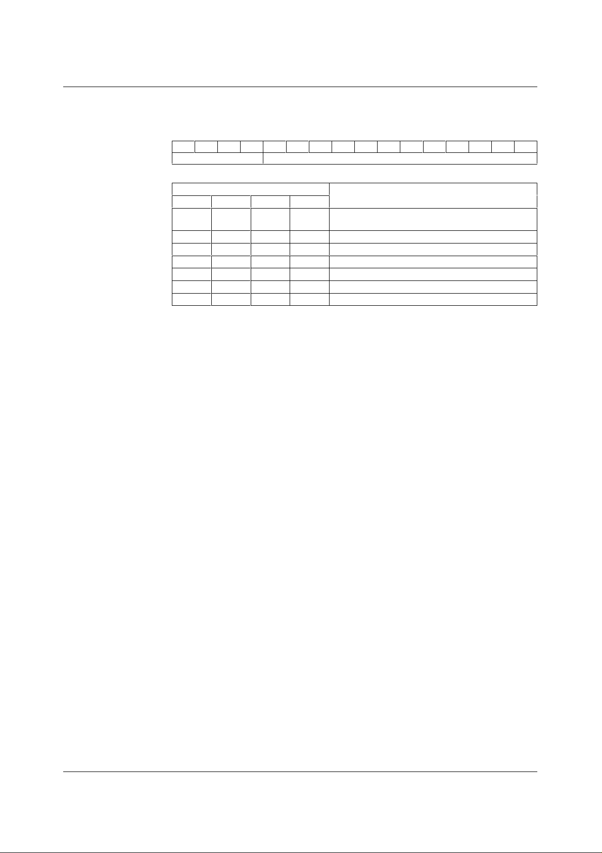
The 16 bits of data can be transf erred with the sequence s hown in Table 2. D11-D0 contai ns t he 12bit data word. D15-D12 hold the programmable options which are summarized i n Tabl e 3.
D15 D14 D13 D12 D11 D10 D9 D8 D7 D6 D5 D4 D3 D2 D1 D0
Program Bits New DAC value
Table 2 Serial Word Format
PROGRAM BITS
D15 D14 D13 D12
1XXX
0XX0
0XX1
X0XX
X1XX
XX0X
XX1X
Table 3 Program Bits D15 to D12 Function
DEVICE FUNCTION
Write to lat ch A with serial interface regis ter data and
latch B updated with buffer latch data.
Write to lat ch B and double buffer latch.
Write to double buf fer latch only.
12µs settling time.
4µs settling time.
Powered-up operation.
Power down mode.
PROGRAMMABLE SETTLING TIME
Settling time is a software selectable 12µs or 4µs, typical to within ±0.5LSB of final value.
This is controlled by the value of D14. A ONE defines a s ettli ng tim e of 4µs, a ZERO defines
a settling time of 12µs.
PROGRAMMABLE POWER DOWN
The power down function is controlled by D13. A ZERO c onfigures the device as active, or
fully powered up, a ONE configures the device into power down mode. W hen the power
down function is released the devic e revert s to the DAC code set prior t o power down.
FUNCTION OF THE LATCH CONTROL BITS (D15 AND D12)
PURPOSE AND USE OF THE DOUBLE BUFFER
Normally only one DAC output can change aft er a write. The double buffer allows both DA C
outputs to change after a si ngl e write. This is achieved by the two following st eps.
• A double buffer only write is executed to st ore the new DAC B data without changing the
DAC A and B outputs.
• Following the previous step, a write to latch A is executed. This writes the s eri al i nt erface
register (SIR) data to latc h A and also writes the double buffer contents to latch B. Thus
both DACs receive their new data at the s ame time and so both DAC outputs begin to
change at the same time.
Unless a double buffer only write is issued, the latch B and double buffer contents are
identical. Thus, foll owing a write to latc h A or B with another write t o l atc h A does not c hange
the latch B contents .
Three data transfer options are possible. All transfers occ ur im m edi ately af ter NCS goes hi gh
(or on the sixteenth positive SCLK edge, whichever is earlier) and are described in the
following sections.
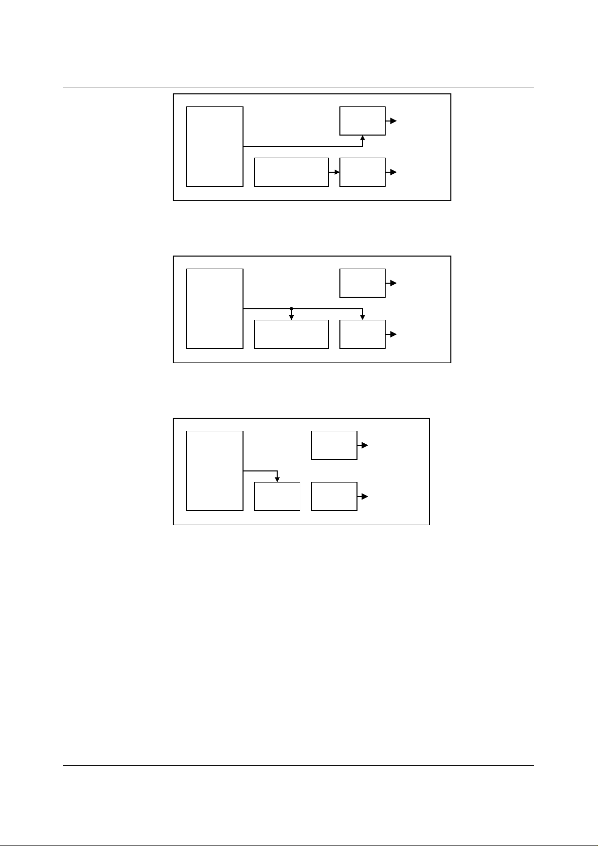
LATCH A WRITE, LATCH B UPDATE (D15 = HIGH, D12 = X)
The serial interface register (SIR) data are written to latch A and the double buffer latch
contents are written to latch B. The double buffer contents are unaf fected. This program bit
condition allows simul taneous output updates of both DACs.
WOLFSON MICROELECTRONICS LTD PD Rev 1.1 October 2000
7
Page 8
WM2618 Production Data
SERIAL
INTERFACE
REGISTER
D12 = X
D15 = HIGH
Figure 2 Latch A Write, Latch B Update
LATCH B AND DOUBLE BUFFER WRITE (D15 = LOW, D12 = LOW)
The SIR data are written to both latch B and the double buffer. Latch A is unaffected.
SERIAL
INTERFACE
REGISTER
D12 = LOW
D15 = LOW
Figure 3 Latch B and Double Buffer Write
DOUBLE BUFFER ONLY WRITE (D15 = LOW, D12 = HIGH)
The SIR data are written to the double buffer onl y. Latch A and B contents are unaffected.
DOUBLE
BUFFER LATCH
DOUBLE
BUFFER LATCH
LATCH A TO DAC A
LATCH B TO DAC B
LATCH A TO DAC A
LATCH B TO DAC B
SERIAL
INTERFACE
REGISTER
D12 = HIGH
D15 = LOW
Figure 4 Double Buffer Only Write
OPERATIONAL EXAMPLES
1. changing the latch A data from zero to full code
Assuming that latch A starts at zero code (e.g. , after power up), the latch can be filled with 1s
by writing (bit D15 on the left, D0 on the right)
1X0X 1111 1111 1111
to the serial interface. Bit D14 can be zero to selec t slow mode or one to select fast mode.
The other X can be zero or one (don’t care).
The latch B contents and DAC B output are not changed by this write unless the double
buffer contents are diff erent from the lat ch B contents. This can only be true if the last write
was a double buffer-only write.
2. changing the latch B data from zero to full code
Assuming that latch B starts at zero code (e.g. , after power up), the latch can be filled with 1s
by writing (bit D15 on the left, D0 on the right).
DOUBLE
BUFFER
LATCH A TO DAC A
LATCH B TO DAC B
0X00 1111 1111 1111
WOLFSON MICROELECTRONICS LTD PD Rev 1.1 October 2000
8
Page 9

Production Data WM2618
to the serial interface. Bit D14 can be zero to selec t slow mode or one to select fast mode.
The data (bits D0 to D11) are written to both the doubl e buffer and latch B.
The latch A contents and t he DAC A output are not changed by this write.
3. double buffered change of both DAC out put s
Assuming that DA Cs A and B start at zero code (e.g., af ter power up), if DAC A is to be
driven to mid-scale and DAC B to full -sc ale, and if t he output s are t o begin ris ing at the s am e
time, this c an be achieved as follows:
First,
0d01 1111 1111 1111
is written (bit D15 on the left, D0 on the right) to the serial interface. This loads the full-scale
code into the double buffer but does not c hange the latch B cont ents and the DAC B output
voltage. The latch A contents and the DAC A output are also unaffected by this write
operation.
Changing from fast to s low to fast mode changes the supply current which can glitch the
outputs, and so D14 (designated by d in the above data word) should be set to maintain the
speed mode set by the previous write.
Next,
1d0X 1000 0000 0000
is written (bit D15 on the left, D0 on the right) to the serial interface. The X in bit D12 can be
zero or one (don’t care). This writes the mid-scale code (100000000000) t o latch A and also
copies the full-scale code from the doubl e buffer to latch B . Both DAC outputs thus begin to
rise after the second write.
WOLFSON MICROELECTRONICS LTD PD Rev 1.1 October 2000
9
Page 10
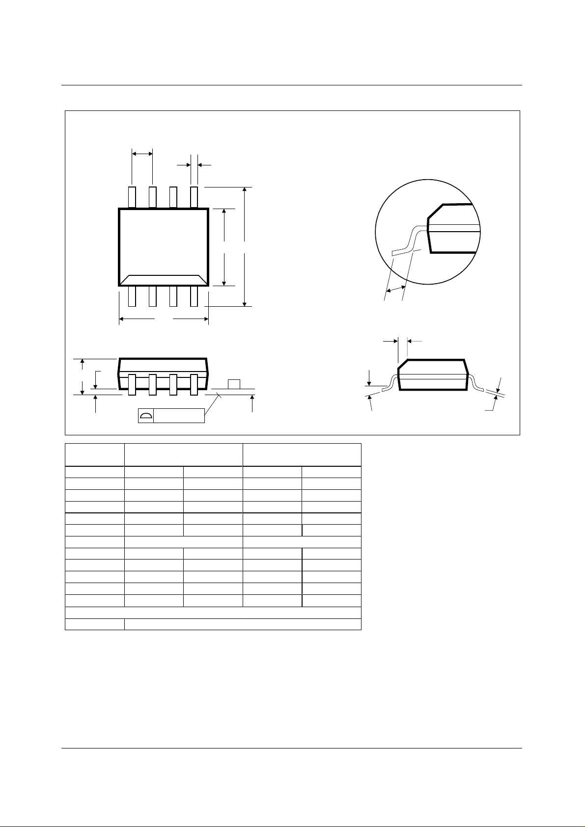
WM2618 Production Data PACKAGE DIMENSIONS
D: 8 PIN SOIC 3.9mm Wide Body
e
D
A1
A
B
58
41
E H
-C-
h x 45
α
DM009.B
L
o
Symbols
0.10 (0.004)
Dimensions
(mm)
SEATING PLANE
Dimensions
(Inches)
MINMAXMINMAX
A
A
1
B
C
D
e
E
h
H
L
α
1.35 1.75 0.0532 0.0688
0.10 0.25 0.0040 0.0098
0.33 0.51 0.0130 0.0200
0.19 0.25 0.0075 0.0098
4.80 5.00 0.1890 0.1968
1.27 BSC 0.050 BSC
3.80 4.00 0.1497 0.1574
0.25 0.50 0.0099 0.0196
5.80 6.20 0.2284 0.2440
0.40 1.27 0.0160 0.0500
o
0
o
8
o
0
o
8
REF: JEDEC.95, MS-012
NOTES:
A. ALL LINEAR DIMENSIONS ARE IN MILLIMETERS (INCHES).
B. THIS DRAWING IS SUBJECT TO CHANGE WITHOUT NOTICE.
C. BODY DIMENSIONS DO NOT INCLUDE MOLD FLASH OR PROTRUSION, NOT TO EXCEED 0.25MM (0.010IN).
D. MEETS JEDEC.95 MS-012, VARIATION = AA. REFER TO THIS SPECIFICATION FOR FURTHER DETAILS.
C
WOLFSON MICROELECTRONICS LTD PD Rev 1.1 October 2000
10
 Loading...