

Page 1
WM2610
Octal 12-bit, Serial Input, Vol t age Output DAC
with Power Down
Production Data, February 2001, Rev 1.0
FEATURES
• Eight 12-bit DACs in one package
• Dual supply 2.7V to 5.5V operation
• DNL ±0.5 LSBs, INL ±2. 0 LS Bs typical
• Programmable settling time / power
(1.0µs typ. in fast mode)
• Microcontroller compatible Serial Interface
• Power Down Mode ( < 0.1µA)
• Monotonic over Temperature
• Data Output for Daisy Chaining
APPLICATIONS
• Battery powered test instruments
• Digital offset and gain adjustment
• Battery operated / remote industrial controls
• Programmable Loop Controllers
• CNC Machine Tools
• Machine and motion control devices
• Wireless telephone and communication systems
• Robotics
ORDERING INFORMATION
DEVICE TEMP. RANGE PACKAGE
WM2610CDT 0° to 70°C 20-pin TSSOP
WM2610IDT -40° to 85°C 20-pin TSSOP
DESCRIPTION
The WM2610 is an octal, 12-bit, resistor string digital-toanalogue converter. The eight individual DA Cs contained in the
IC can be switched in pairs between fast and slow (low power)
operation modes, or powered down, under software control.
Alternatively, the whole device can be powered down, reducing
current consumption to less than 0.1µA.
The DAC outputs are buffered by a rail -to-rail amplifier with a
gain of two, which is configurable as Class A (fast mode) or
Class AB (for low-power mode).
The WM2610 has been designed to interfac e direc tl y to indus try
standard microprocess ors and DSPs, and can operate on two
separate analogue and digital power supplies. It is program med
with a 16-bit serial word comprising 4 address bits and up to 12
DAC or control register data bits. All eight DACs can be
simultaneously forced to a preset value using a preset input pin.
A daisy-chain data output mak es i t pos sibl e to c ontrol several of
Wolfson’s octal DACs from the same interface, without
increasing the number of c ontrol lines.
The device is available in a 20-pin TSSOP package.
Commercial temperature (0° to 70°C) and Industrial
temperature (-40° to 85°C) variants are supported.
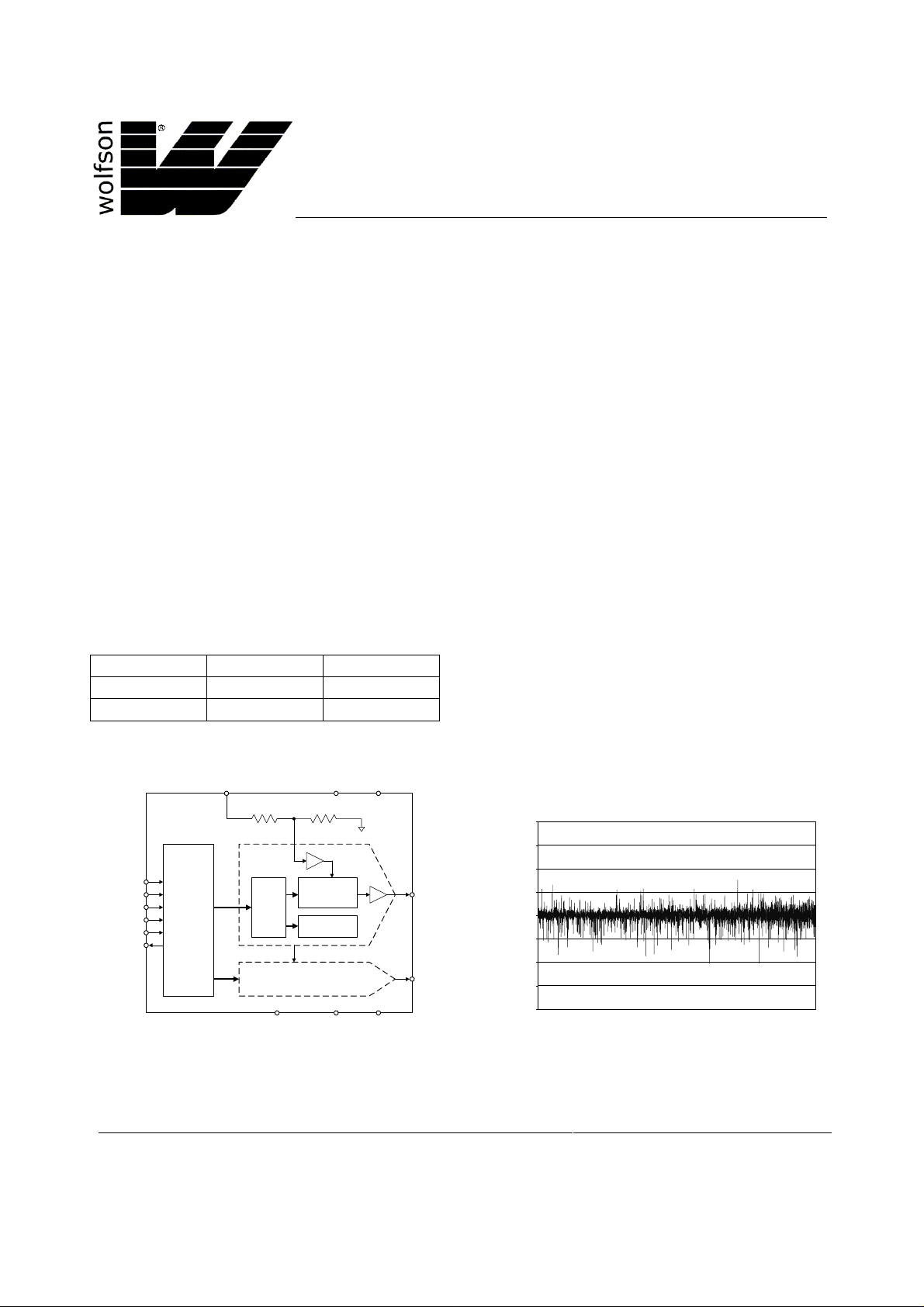
BLOCK DIAGRAM TYPICAL PERFORMANCE
AVDD
REF
(16)
DAC A
DIN (2)
SCLK (3)
FS (4)
MODE (17)
PREB (5)
DOUT (19)
SERIAL
INTERFACE
AND
CONTROL
LOGIC
LATCH
DACs B, C, D, E, F, G, H
LOADB
(18)
RESISTOR
POWER/SPEED
CONTROL
VREF/2
as DAC A
STRING
WOLFSON MICROELECTRONICS LTD
Bernard Terrace, Edinburgh, EH8 9NX, UK
Tel: +44 (0) 131 667 9386
Fax: +44 (0) 131 667 5176
Email: [email protected]
www.wolfsonmicro.co.uk
(11)
AGND
(10)
DVDD
(20)
DGND
(1)
(12) OUT A
(6-9, 13-15)
OUT B to H
1
0.75
0.5
0.25
0
-0.25
Differential Non-Linearity (LSBs)
-0.5
-0.75
-1
0 512 1024 1536 2048 2560 3072 3584 4096
DIGITAL CODE
Production Data datasheets contain final
specifications current on publication date.
Supply of products conforms to Wol fson
Microelectronics’ Term s and Conditions.
2001 Wolfson Microelectronics Ltd.
Page 2
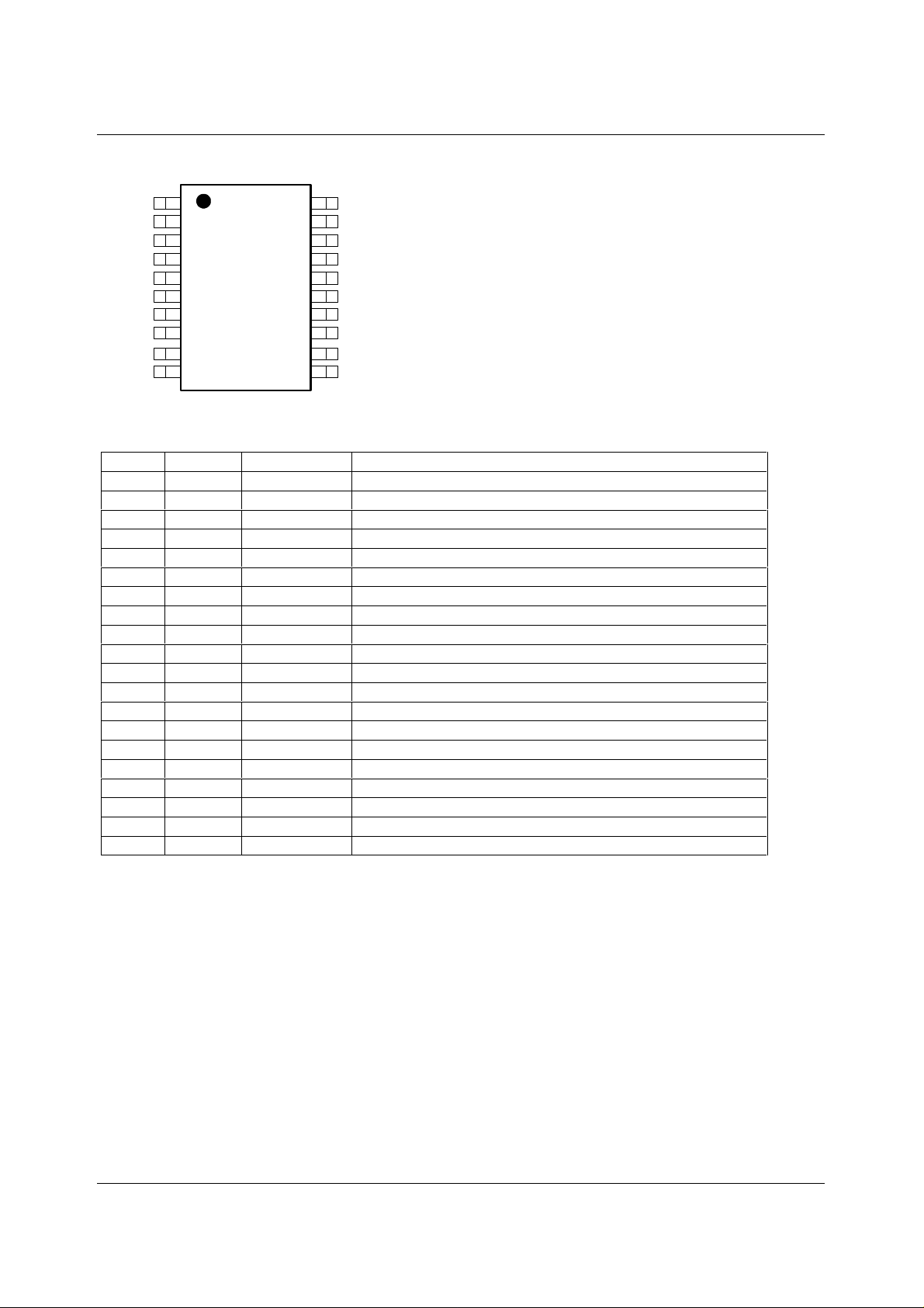
WM2610 Production Data PIN CONFIGURATION
20
DGND
DIN
SCLK
PREB
OUTE
OUTF
OUTG
OUTH
AGND
1
2
3
FS
4
5
6
7
8
9
10
DVDD
19
DOUT
18
LOADB
17
MODE
16
REF
15
OUTD
14
OUTC
13
OUTB
12
11
OUTA
AVDD
PIN DESCRIPTION
PIN NO NAME TYPE DESCRIPTION
1
2
3
4
5
6
7
8
9
10
11
12
13
14
15
16
17
18
19
20
DGND Supply Digital Ground
DIN Digital input Digital serial data input
SCLK Digital input Serial clock input
FS Digital input Frame sync input
PREB Digital input Preset input
OUTE Analogue output DAC Output E
OUTF Analogue output DAC Output F
OUTG Analogue output DAC Output G
OUTH Analogue output DAC Output H
AGND Supply Analogue Ground
AVDD Supply Analogue positive power supply
OUTA Analogue output DAC Output A
OUTB Analogue output DAC Output B
OUTC Analogue output DAC Output C
OUTD Analogue output DAC Output D
REF Analogue I/O Voltage reference input / output
MODE Digital input Input mode
LOADB Digital input Load DAC
DOUT Digital output Data serial data output
DVDD Supply Digital positive power supply
WOLFSON MICROELECTRONICS LTD PD Rev 1.0 February 2001
2
Page 3
Production Data WM2610
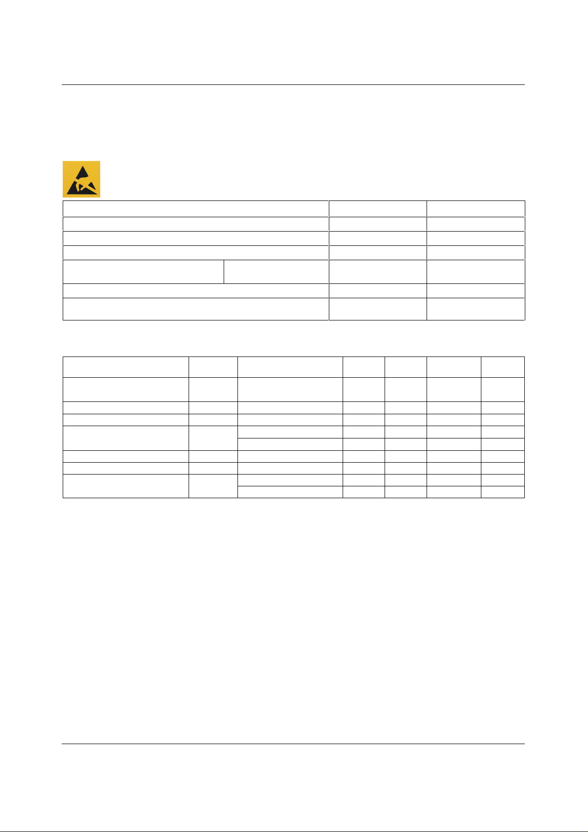
ABSOLUTE MAXIMUM RATINGS
Absolute Maximum Ratings are stress ratings only. P ermanent dam age to the device m ay be caused by c ontinuously operating at
or beyond these limits. Device f unctional operating limits and guaranteed perform ance specifications are given under Electric al
Characteristics at the test conditions s pecified.
ESD Sensitive Device. Thi s device is manufact u red on a CMOS process. It is theref ore generi cally susceptible to
damage from excessive static voltages . Proper ESD precautions mus t be taken during handling and storage of
this device.
CONDITION MIN MAX
Digital supply voltages, AVDD or DVDD to GND
Reference voltage
Digital input voltage range to GND
Operating temperature range, T
A
WM2610CDT
WM2610IDT
Storage temperature
Soldering temperature, 1.6mm (1/16 inch) from package body for 10
-0.3V AVDD + 0.3V
-0.3V DVDD + 0.3V
0°C
-40°C
-65°C 150°C
7V
70°C
85°C
260°C
seconds
RECOMMENDED OPERATING CONDITIONS
PARAMETER SYMBOL TEST CONDITIONS MIN TYP MAX UNIT
Supply voltage
High-level digital input voltage
Low-level digital input voltage
Reference voltage to REF
Output Load Resistance
Load capacitance
Operating free-air temperature
AVDD,
DVDD
V
IH
V
IL
V
REF
R
L
C
L
T
A
2.7 5.5 V
2V
0.8 V
AVDD = 5V GND 4.096 AVDD
AVDD = 3V GND 2.048 AVDD V
2kΩ
100 pF
WM2610CDT 0 70 °C
WM2610IDT -40 85 °C
WOLFSON MICROELECTRONICS LTD PD Rev 1.0 February 2001
3
Page 4
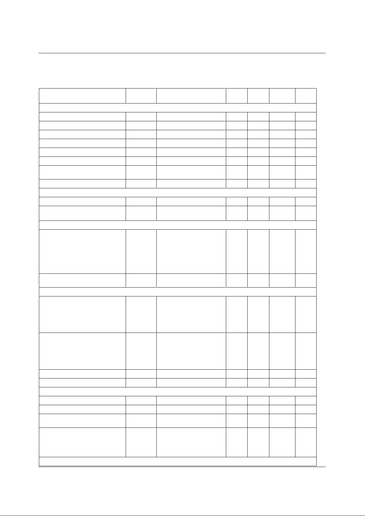
WM2610 Production Data ELECTRICAL CHARACTERISTICS
Test Characteristics:
Over recommended operating condi tions (unless noted otherwise).
PARAMETER SYMBOL
TEST
CONDITIONS
MIN TYP MAX UNIT
Static DAC Specifications
Resolution
Integral non-linearity
Differential non-linearity
Zero code error
Gain error
DC power supply rejection ratio
Zero code error temperature
INL Code 40 to 4095 (see Note 1) ±2 ±6 LS B
DNL Code 40 to 4095 (see Note 2) ±0.5 ±1 LS B
ZCE See Note 3 ±30 mV
GE See Note 4 ±0.6 % FSR
PSRR See Note 5 -60 dB
See Note 6 30 µV/°C
12 bits
coefficient
Gain error temperature coefficient
See Note 6 10 ppm/°C
DAC Output Specifications
Output voltage range
Output load regulation
10kΩ Load 0 AVDD-0.4 V
2kΩ to 10kΩ load
±0.3 % Full
See Note 7
Scale
Power Supplies
Active supply current
IDD No load, V
=DVDD, VIL=0V
IH
AVDD = DVDD = 5V,
V
= 2.048V
REF
Slow
Fast
16
6
21
8
mA
mA
See Note 8
Power down supply current
No load, all inputs 0V
0.1 µA
or DVDD
Dynamic DAC Specifications
Slew rate
DAC code 10%-90%
Load = 10kΩ, 100pF
Fast
Slow
4
1
10
V/µs
3
V/µs
See Note 9
Settling time
DAC code 10%-90%
Load = 10kΩ, 100pF
Fast
Slow
1
3
3
7
µs
µs
See Note 10
Glitch energy
Channel Crosstalk
Code 2047 to code 2048 4 nV-s
10kHz sine wave, 4V pk-pk -90 dB
Reference Input
Reference input resistanc e
Reference input capacitanc e
Reference feedthrough
RREF 100 kΩ
CREF 5 pF
V
=2VPP at 1kHz
REF
-84 dB
+ 2.048V DC, DAC code 0
Reference input bandwidth
V
= 0.4VPP + 2.048V DC,
REF
DAC code 2048
Slow
Fast
1.9
2.2
MHz
MHz
Digital Inputs
WOLFSON MICROELECTRONICS LTD PD Rev 1.0 February 2001
4
Page 5

Production Data WM2610
Test Characteristics:
Over recommended operating condi tions (unless noted otherwise).
PARAMETER SYMBOL
High level input current
Low level input current
Input capacitance
I
IH
I
IL
C
I
TEST
CONDITIONS
MIN TYP MAX UNIT
Input voltage = DVDD 1 µA
Input voltage = 0V -1 µA
8pF
Digital Output
High level digital output volt age
Low level digital output voltage
Output voltage rise time
V
OH
V
OL
Load = 10kΩ 2.6 V
Load = 10kΩ 0.4 V
Load = 10kΩ, 20pF, includes
720ns
propagation delay
Notes:
1. Integral non-linearity (INL) is the m axim um deviation of the output from the line between zero and full scale excluding
the effects of zero c ode and full scale errors).
2. Differential non-linearity (DNL) is the difference between the measured and ideal 1LSB amplit ude change
of any adjacent two codes. A guarantee of monotonicity means the output voltage changes in the same
direction (or remains constant) as a change in digital i nput code.
3. Zero code error is the voltage output when the DAC input code i s zero.
4. Gain error is the deviation from the ideal full-scale output excluding the effec t s of zero code error.
5. Power supply rejection ratio is measured by varying AVDD from 4.5V to 5.5V and measuring the
proportion of this signal imposed on the zero code error and the gain error.
6. Zero code error and Gain error temperature coefficients are norm al i sed to full-scale voltage.
7. Output load regulation is the difference between the output voltage at full scale with a 10kΩ load and 2kΩ
load. It is expressed as a percent age of the full scale output vol tage with a 10kΩ load.
8. I
is measured while continuous l y writing code 2048 to the DAC. For VIH < DVDD - 0.7V and VIL > 0.7V
DD
supply current will increase.
9. Slew rate results are for the lower value of the rising and falling edge s l ew rates.
10. Settling time is the time taken for the signal to settle to within 0.5LSB of the final measured val ue for both rising and
falling edges. Limits are ensured by design and characterisation, but are not production tested.
WOLFSON MICROELECTRONICS LTD PD Rev 1.0 February 2001
5
Page 6
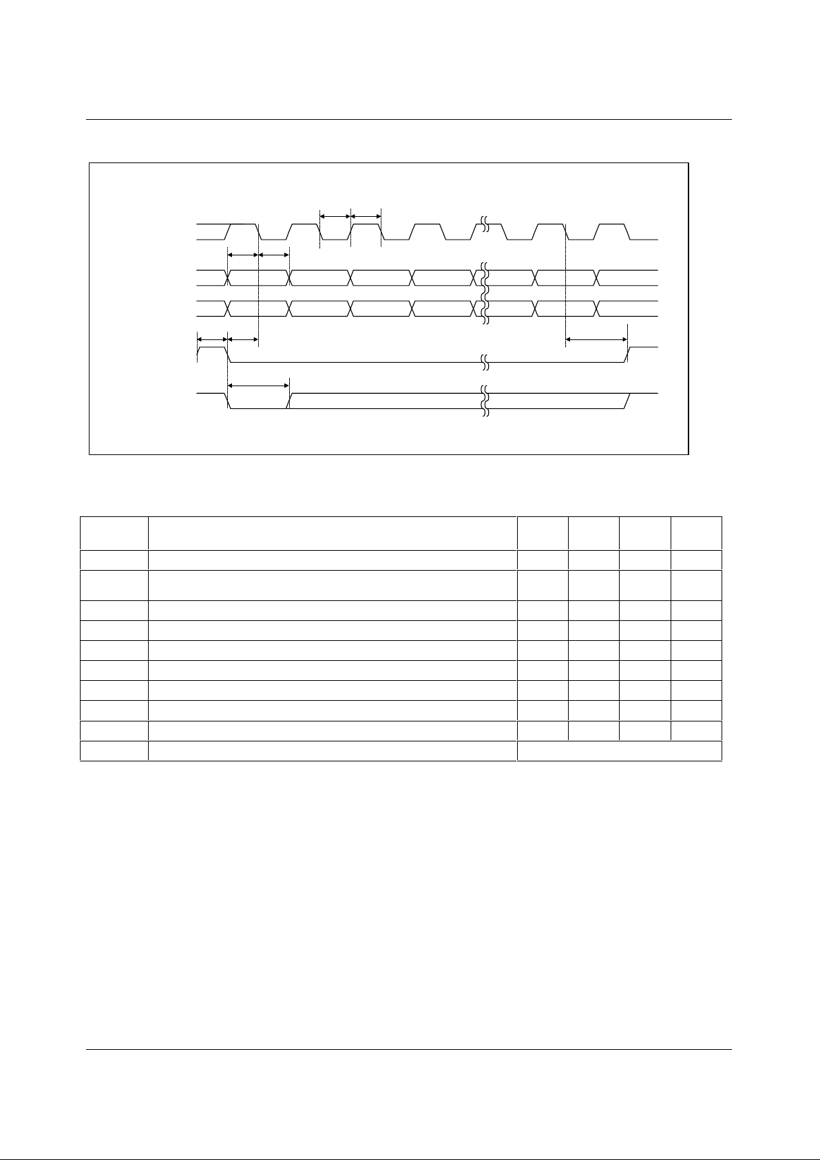
WM2610 Production Data SERIAL INTERFACE
t
t
WL
WH
SCLK
DIN
DOUT
FS
(
µ
C MODE)
FS
(DSP MODE)
X1 2
t
SUD
t
HD
XD15 D14 D13
X D15 * D14 * D13 * D12 * D1 * D0 * X
t
WHFStSUFSCLK
* DIN data from previous word
(delayed by 16 clock cycles)
t
WLFS
No high to low transitions
Figure 1 Timing Diagram
SYMBOL TEST
CONDITIONS
t
SUFSCLK
t
C16-FS
Setup time, FS pin low before fi rst falling edge of SCLK
Setup time, 16th falling clock edge after FS l ow to ris i ng edge of FS
(only used in microcont rol l er mode)
t
WLOADB
t
WH
t
WL
t
SUD
t
HD
t
WHFS
t
WLFS
t
s
Pulse duration, LOADB low
Pulse duration, SCLK high
Pulse duration, SCLK low
Setup time, data ready before SCLK falling edge
Hold time, data held valid after SCLK falling edge
Pulse duration, FS high
Pulse duration, FS low
DAC Output settling ti me
34 16
2
D1 D0 X
t
SUC16-FS
MIN TYP MAX UNIT
8ns
10 ns
10 ns
16 ns
16 ns
8ns
5ns
10 ns
10 ns
see Dynamic DAC Speci fications
X
WOLFSON MICROELECTRONICS LTD PD Rev 1.0 February 2001
6
Page 7
Production Data WM2610
Figure
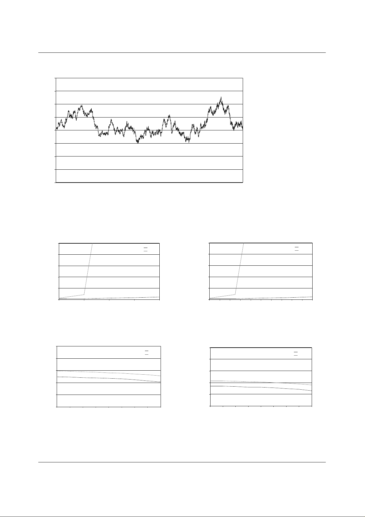
TYPICAL PERFORMANCE GRAPHS
4
3
2
1
0
-1
-2
Integral Non-Linearity (LSBs)
-3
-4
0 512 1024 1536 2048 2560 3072 3584 4096
DIGITAL CODE
Figure 2 Integral Non-Linearity
1
VDD = 3V
= 1.024V
V
REF
Input Code = 0
0.8
0.6
0.4
Output Voltage (V)
0.2
0
00.511.52
Sink Current (mA)
Slow
Fast
1
VDD = 5V
V
= 2.048V
REF
Input Code = 0
0.8
0.6
0.4
Output Voltage (V)
0.2
0
0 0.2 0.4 0.6 0.8 1 1.2 1.4 1.6 1.8 2
Sink Current (mA)
Slow
Fast
Figure 3 Output Load Regulation (Sink) AVDD = 3V Figure 4 Output Load Regulation (Sink) AVDD = 5V
2.1
VDD=3V
=1.024V
V
REF
Input Code = 4095
2.08
2.06
2.04
DACA (Volts)
2.02
2
Sourcing Current (mA)
Slow
Fast
-4-3.5-3-2.5-2-1.5-1-0.50
4.15
VDD=5V
=2.048V
V
REF
Input Code = 4095
4.13
4.11
4.09
DACA (Volts)
4.07
4.05
Sourcing Curre nt (mA)
Slow
Fast
-4-3.5-3-2.5-2-1.5-1-0.50
Figure 5 Output Load Regulation (Source) AVDD = 3V
6 Output Load Regulation (Source) AVDD = 5V
WOLFSON MICROELECTRONICS LTD PD Rev 1.0 February 2001
7
Page 8
WM2610 Production Data DEVICE DESCRIPTION
GENERAL FUNCTION
The WM2610 is an octal 12-bit, voltage output DAC. It contains a serial interface, control logic for
speed and power down, a programmable voltage reference, and eight digit al to analogue converters .
Each converter uses a resi stor string network buffered with an op amp to convert 12-bit digital data to
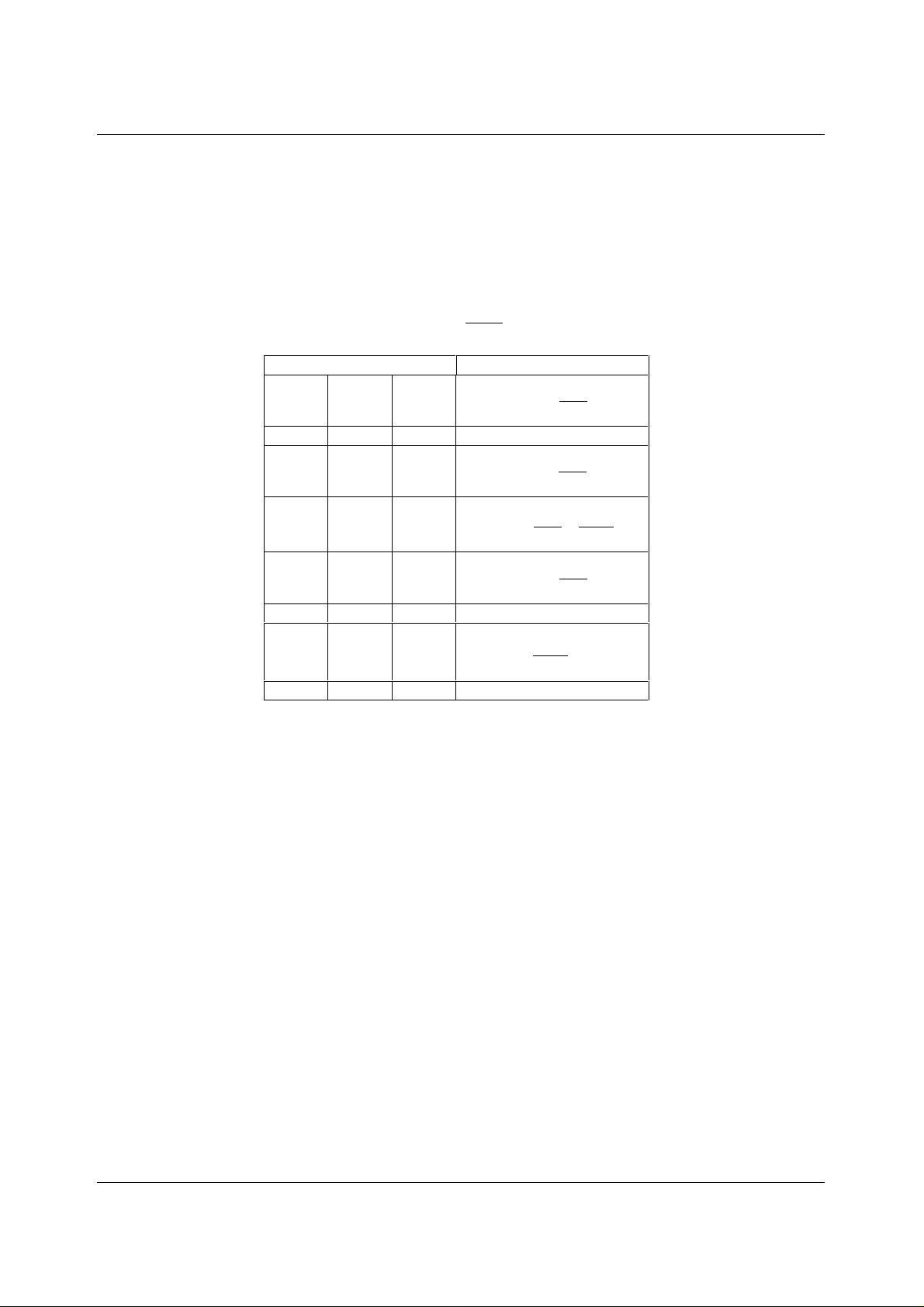
analogue voltage levels (see Block Diagram). The output voltage is determined by the reference
input voltage and the input code according to the following relationship:
Output voltage =
INPUT OUTPUT
1111 1111 1111
::
1000 0000 0001
1000 0000 0000
0111 1111 1111
::
0000 0000 0001
0000 0000 0000 0V
Table 1 Binary Code Table
V ×
REF
CODE
4096
V =×
REF
V
V
V
REF
REF
REF
2048
4096
V
REF
4096
×
×
×
4095
4096
2049
4096
2047
4096
V
REF
2
POWER ON RESET
An internal power-on-reset circuit resets the DAC register to al l 0s on power-up.
BUFFER AMPLIFIER
The output buffer has a near rail-to-rail out put with short circuit protec tion and can reliably drive a
2kΩ load with a 100pF load capacitance.
WOLFSON MICROELECTRONICS LTD PD Rev 1.0 February 2001
8
Page 9
Production Data WM2610
SERIAL INTERFACE
INTERFACE MODES
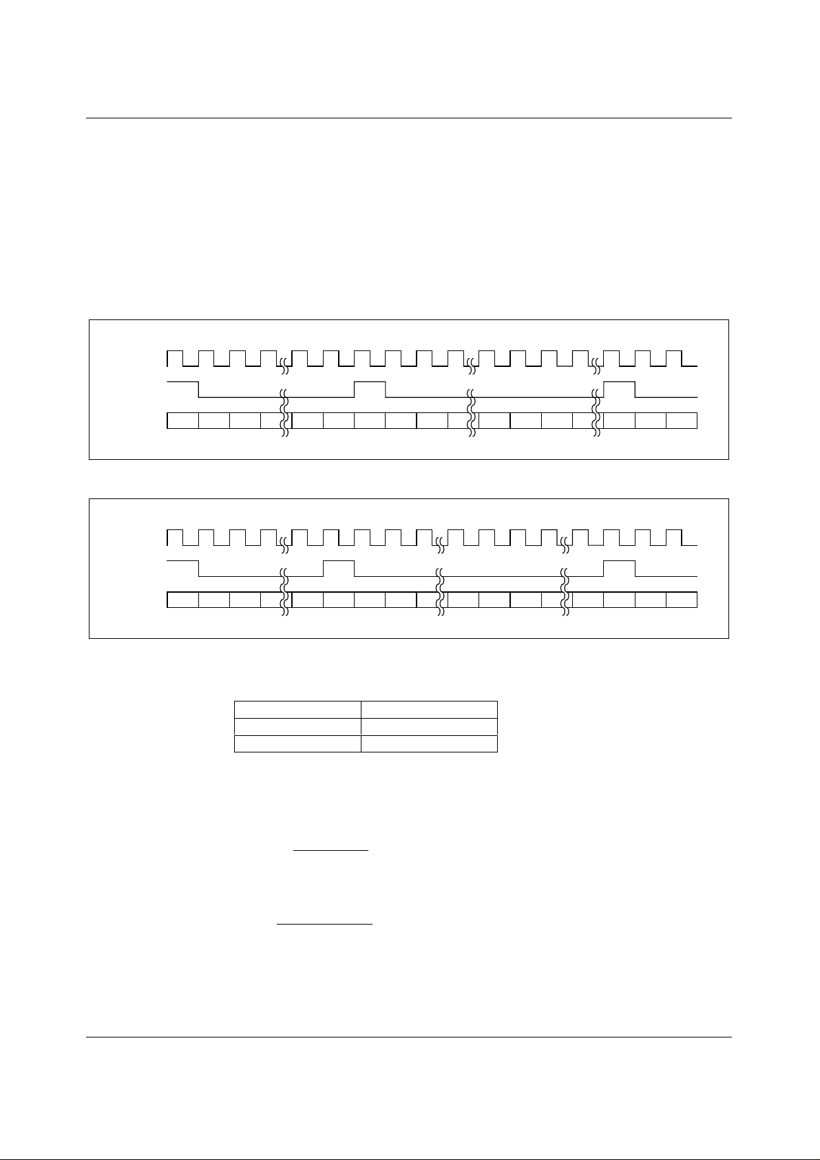
The control interface can operate in two different modes:
• In the microcontroller mode, FS needs to be held low until all 16 data bits have been
transferred. If FS is dri ven high before the 16
The DAC is updated after a rising edge on FS .
• In DSP mode, FS only needs to stay low for 20ns, and can go high before the 16
edge.
SCLK
FS
X
D15
DIN
Figure 7 Interface Timing in Microcontroller Mode
SCLK
FS
DIN
X
D14 D1 D0 X E15
D15
D14 D1 D0 E15 E14 E0 X X F15
E14
th
falling clock edge, t he data transf er is cancell ed.
E1 E0 X F15
E1
X
X
th
falling clock
F14
F14
Figure 8 Interface Timing in DSP Mode
The operating mode is selected using pin 17 (MODE).
MODE PIN (17) INTERFACE MODE
HIGH Microcontroller
LOW or unconnected DSP mode
Table 2 Interface Mode Selection
SERIAL CLOCK AND UPDATE RATE
Figure 1 shows the interface timing. The maximum serial clock rate is:
f
Since a data word contains 16 bits, the sample rate is li mited to
f
However, the DAC settling time t o 12 bits accuracy lim its the response t ime of the analogue output
for large input step transit i ons.
WOLFSON MICROELECTRONICS LTD PD Rev 1.0 February 2001
SCLK
s
max
max
=
=
16
1
tt
+
WLWH
1
tt
+
()
WLWH
MHz
31
=
minmin
MHz
95.1
=
minmin
9
Page 10
WM2610 Production Data
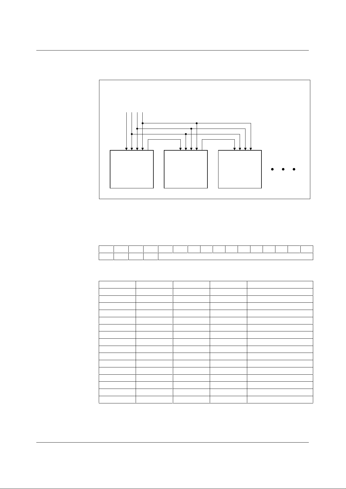
DAISY CHAINING MULTIPLE DEVICES
The DOUT output (pin 19) provides the data sam pled on DIN with a delay of 16 c lock cycles. This
signal can be used to control anot her WM2610 or similar devi ce in a daisy-chain type circuit .
DIN
SCLK
LOADB
FS
FS
DIN
SCLK
DOUT
LOADB
OCTAL DAC #1
Figure 9 Daisy Chaining
SOFTWARE CONFIGURATION OPTIONS
DATA FORMAT
The WM2610 is controll ed with a 16-bi t code consisting of four addres s bits, A0-A3, and 12 data bit s.
D15 D14 D13 D12 D11 D10 D9 D8 D7 D6 D5 D4 D3 D2 D1 D0
A3 A2 A1 A0 Data
Table 3 Input Data Format
Using the four address bits , 16 different registers c an be addressed.
A3 A2 A1 A0 REGISTER
0 0 0 0 DAC A Code
0 0 0 1 DAC B Code
0 0 1 0 DAC C Code
0 0 1 1 DAC D Code
0 1 0 0 DAC E Code
0 1 0 1 DAC F Code
0 1 1 0 DAC G Code
0 1 1 1 DAC H Code
1 0 0 0 Control Regi ster 0
1 0 0 1 Control Regi ster 1
1 0 1 0 Preset all DACs
1 0 1 1 RESERVED
1 1 0 0 DA C A and complement B
1 1 0 1 DAC C and compl ement D
1 1 1 0 DAC E and complem ent F
1 1 1 1 DAC G and complement H
Table 4 Register Map
FS
DIN
SCLK
OCTAL DAC #2
FS
DIN
DOUT
LOADB
OCTAL DAC #3
SCLK
DOUT
LOADB
WOLFSON MICROELECTRONICS LTD PD Rev 1.0 February 2001
10
Page 11
Production Data WM2610
DAC A TO H CODE REGISTERS
Addresses 0 to 7 are the DAC registers. The data written to these regist ers is transferred to the
respective DAC when the LOADB input (pin 18) is low. For instant aneous updating, LOADB can be
held low permanently.
CONTROL REGISTER 0
Control register 0 (address 8) is used to select func tions that apply to the whole IC, such as Power
Down and Data Input Format.
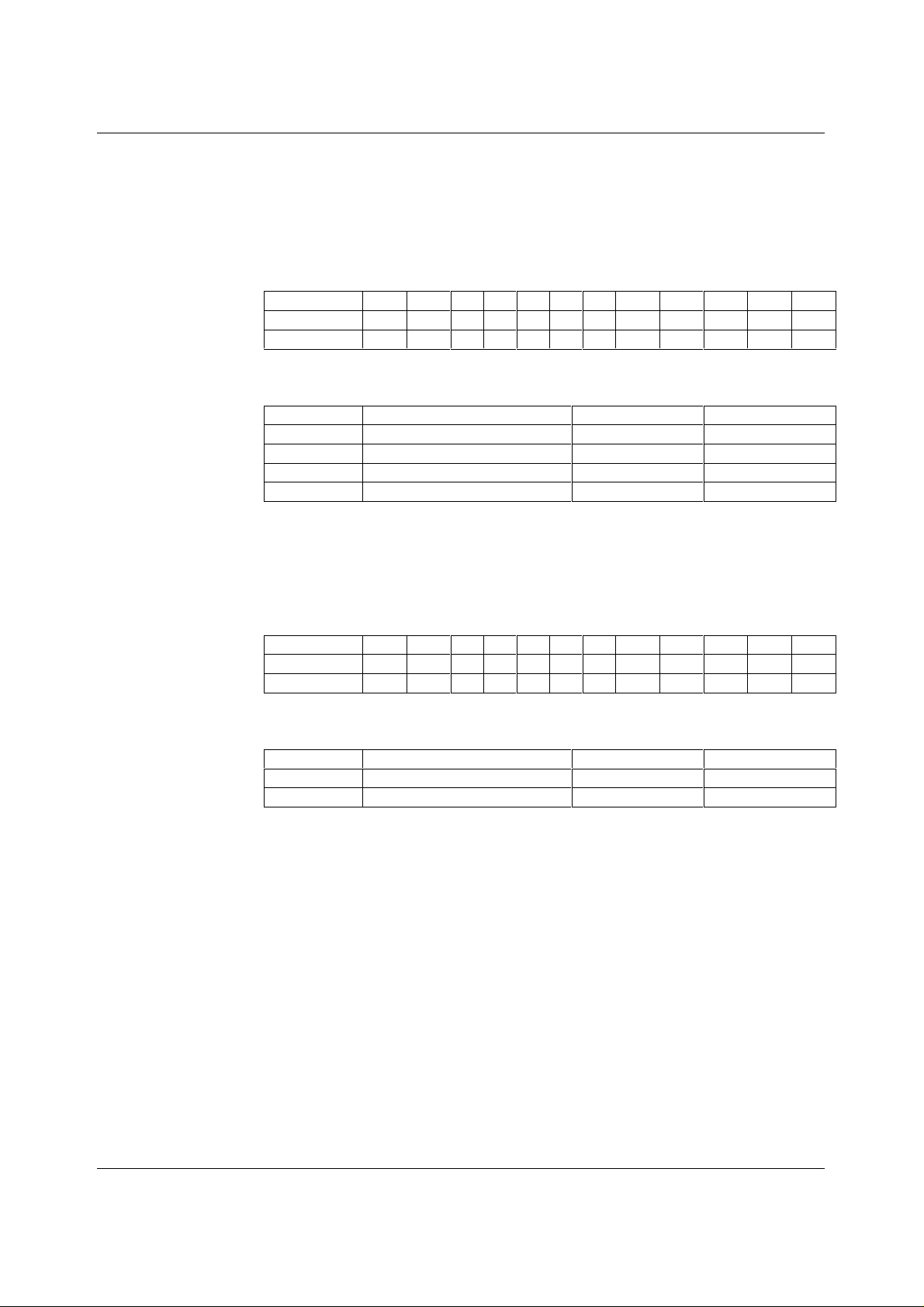
BIT D11 D10D9D8D7D6D5 D4 D3 D2 D1 D0
Function X X XXXXXPDDO X X IM
Default X X XXXXX 0 0000
Table 5 Register Map
BIT DESCRIPTION 0 1
PD Full devic e Power Down Normal Power Down
DO DOUT Enable Disabled Enabled
IM Input Mode Straight Binary Two’s Complement
X Reserved
Table 6 Register Map
CONTROL REGISTER 1
Control register 1 (address 9) is used to power down individual pairs of DACs and s elect thei r set tl ing
time. Powering down a pair of DACs disabl es their am plif iers and reduces the power cons umpt ion of
the device. The settling t ime in fas t mode is typically 1µs. In s low mode, the s ettling time is typic ally
3µs and power consumption is reduced.
BIT D11 D10D9D8D7D6D5 D4 D3 D2 D1 D0
Function X X X X PGHPEFPCDP
S
S
S
AB
GH
EF
S
CD
AB
Default X X X X 0 0 0 0 0 0 0 0
Table 7 Register Map
BIT DESCRIPTION 0 1
P
XY
S
XY
Power Down DACs X and Y Normal Power Down
Speed Setting for DACs X and Y Slow Fast
Table 8 Register Map
DAC PRESET REGISTER
The Preset register (address 10) m akes it possi ble to update all eight DACs at the same t ime. The
value stored in this register becomes the digital input to all the DACs when the asynchronous PRE B
input (pin 5) is driven low. If no data has previously been written to the preset register, all DA Cs are
set to zero scale.
TWO-CHANNEL REGISTERS
The two-channel registers (addresses 12 t o 15) provide a ‘differential output’ func tion where writing
data to one DAC will automatically write the complem ent to the other DAC in the pair. For example,
writing a hexadecimal value of FFFF to address 12 will set DAC A to full scale and DAC B t o zero
scale.
WOLFSON MICROELECTRONICS LTD PD Rev 1.0 February 2001
11
Page 12

WM2610 Production Data APPLICATIONS INFORMATION
LINEARITY, OFFSET, AND GAIN ERROR
Amplifiers operating from a single supply can have positive or negative voltage offsets. With a
positive offset, the output voltage changes on the first code transition. However, if the offset is
negative, the output voltage m ay not change with the first code, depending on t he magnitude of the
offset voltage. This i s because with the m ost negat ive supply rail being ground, any att empt to drive
the output amplifier below ground will clamp the output at 0 V. The output voltage t hen remains at
zero until the input code is s ufficiently high to overc ome the negative offs et voltage, resulting in the
transfer function shown in Figure 10.
Output
Voltage
0 V
Negative
Offset
Figure 10 Effect of Negative Offset
This offset error, not t he linearity error, produces the break point. The transfer function would follow
the dotted line if the output buf fer could drive below the ground rail.
DAC linearity is measured between zero-input code (all input bi ts at 0) and full -scale code (al l inputs
at 1), disregarding offset and full-scale errors. However, due to the break poi nt in the transfer function,
single supply operation does not al low for adjustm ent when the offs et is negative. In s uch cas es, the
linearity is therefore m easured between full-s cale and the l owest code that produces a posi tive (nonzero) output voltage.
DAC code
POWER SUPPLY DECOUPLING AND GROUNDING
Printed circuit boards with separate analogue and digital ground planes deliver the best system
performance. The two ground planes should be connected together at the low impedance power
supply source. Ground currents should be managed so as to minimise voltage drops across the
ground planes.
A 0.1µF decoupling capacitor should be connected between the pos itive supply and ground pins of
the DAC, with short leads as close as possibl e to the devic e. Use of f errite beads may f urther isolat e
the system analogue suppl y from the digital supply.
WOLFSON MICROELECTRONICS LTD PD Rev 1.0 February 2001
12
Page 13
Production Data WM2610
PACKAGE DIMENSIONS
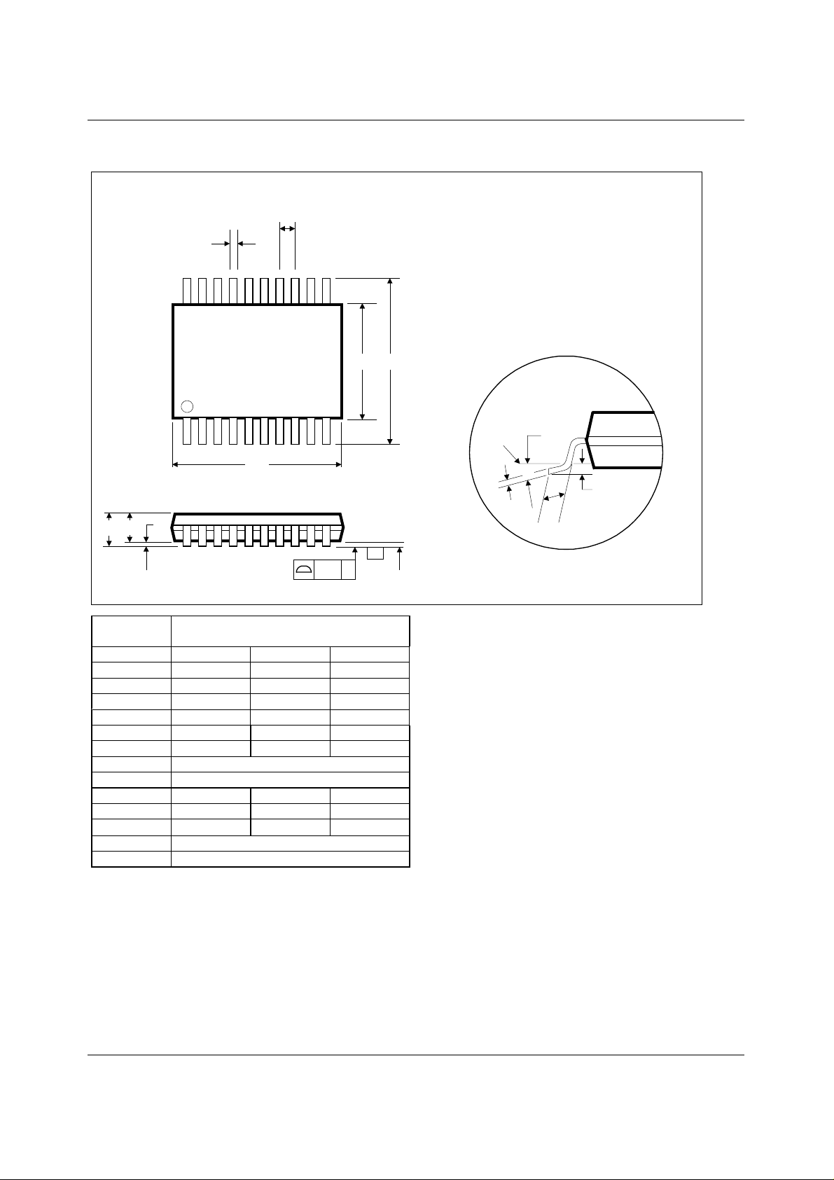
DT: 20 PIN TSSOP (6.5 x 4.4 x 1.0 mm)
b
A1
A2
A
e
1120
D
101
0.1
E1 E
C
-C-
SEATING PLANE
GAUGE
PLANE
DM008.D
θ
0.25
c
L
Dimensions
Symbols
(mm)
MIN NOM MAX
A
A
1
A
2
b
c
D
e
E
E
1
L
θ
REF:
NOTES:
A. ALL LINEAR DIMENSIONS ARE IN MILLIMETERS.
B. THIS DRAWING IS SUBJECT TO CHANGE WITHOUT NOTICE.
C. BODY DIMENSIONS DO NOT INCLUDE MOLD FLASH OR PROTRUSION, NOT TO EXCEED 0.25MM.
D. MEETS JEDEC.95 MO-153, VARIATION = AC. REFER TO THIS SPECIFICATION FOR FURTHER DETAILS.
----- ----- 1.20
0.05 ----- 0.15
0.80 1.00 1.05
0.19 ----- 0.30
0.09 ----- 0.20
6.40 6.50 6.60
0.65 BSC
6.4 BSC
4.30 4.40 4.50
0.45 0.60 0.75
o
0
----- 8
JEDEC.95, MO-153
o
WOLFSON MICROELECTRONICS LTD PD Rev 1.0 February 2001
13
 Loading...