

Page 1
Peak Reducing EMI Solution
W180
Cypress Semiconductor Corporation
• 3901 North First Street • San Jose • CA 95134 • 408-943-2600
July 21 , 2000, rev. *A
Features
•
Cypress PREMIS™ family offering
• Generates an EMI optimized c locking signal at the
output
• Selectable output frequency range
• Single 1.25% or 3.75% dow n or center spread output
• Integrated loop filter components
• Operates with a 3.3V or 5V supply
• Low power CMOS design
• Available in 8-pin SOIC (Small Outline Integrated
Circuit)
Key Specifications
Supply Voltages: .... .......... ... ......... ... .. .......... ..VDD = 3.3V±5%
or V
DD
= 5V±10%
Frequency Range: ................... ...........8 M Hz ≤ F
in
≤
28 MHz
Cycle to Cy c le Ji tte r: .. ... ......... ... .. .......... ... ....... 300 ps (max .)
Selectabl e Spread Percentage: ....................1.25% or 3.75%
Output Duty Cycle: ............................... 40/60% (worst case)
Output R is e a n d Fall Tim e : .......... ... .......... .. ......... 5 ns (max.)
T able 1. Modulation Width Selection
SS%
W180-01, 02, 03
Output
W180-51, 52, 53
Output
0F
in
≥
F
out
≥
F
in
–
1.25%
F
in
+ 0.625% ≥ F
in
≥
–
0.625%
1F
in
≥
F
out
≥
F
in
–
3.75%
F
in
+ 1.875% ≥ F
in≥
–1.875%
Table 2. Frequency Range Selection
FS2 FS1
W180 Option#
-01, 51
(MHz)
-02, 52
(MHz)
-03, 53
(MHz)
008 ≤ F
IN
≤
10 8 ≤ F
IN
≤
10 N/A
0 1 10 ≤ F
IN
≤
15 10 ≤ F
IN
≤
15 N/A
1 0 15 ≤ F
IN
≤
18 N/A 15 ≤ F
IN
≤
18
1 1 18 ≤ F
IN
≤
28 N/A 18 ≤ F
IN
≤
28
PREMIS is a trademark of Cypress Semiconductor Corporation.
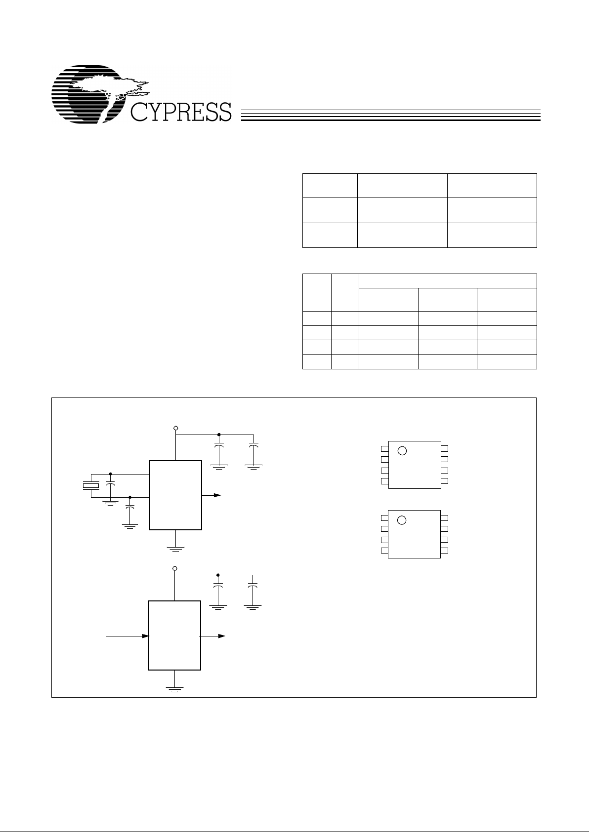
Simplified Block Diagram
Pin Configurations
Spread Spectrum
W180
(EMI su ppressed)
3.3V or 5.0V
Oscilla tor or
Spread Spectrum
W180
(EMI suppressed)
3.3V or 5.0 V
XTAL
X1
X2
Reference Input
Input
Output
Output
W180-02/03
8
7
6
5
1
2
3
4
CLKIN or X1
NC or X2
GND
SS%
SSON#
FS1
VDD
CLKOUT
W180-01/51
8
7
6
5
1
2
3
4
CLKIN or X1
NC or X2
GND
SS%
FS2
FS1
VDD
CLKOUT
SOIC
W180-52/53
Page 2
W180
2
Pin Definitions
Pin Name Pin No.
Pin
Ty pe Pin Description
CLKOUT 5 O
Output Modulated Frequency
: Frequency modulated copy of the unmodu-
lated input clock (SSON# asserted).
CLKIN or X1 1 I
Crystal Connection or External Reference Frequency Input:
This pin has
dual functions. It may either be connected to an ex ternal crystal, or to an
external reference clock.
NC or X2 2 I
Crystal Connection:
Input connectio n for an external crystal. If using an ex-
ternal reference, this pin mus t be left unconnected.
SSON# 8 (-02, -03
52, 53)
I
Spread Spectrum Contro l (Active LOW):
Asserting this signal (acti ve LOW )
turns the internal modulat ion wav e f orm on. Thi s pin has an internal pul l-do wn
resistor.
FS1:2 7, 8 (-01, 51) I
Frequency Selection Bit(s) 1 and 2:
These pins select the frequency range
of operation. Refer to Table 2. These pins have internal pull-up resistors .
SS% 4 I
Modulation Width Selection:
When Spread Spectrum featu re is turned on,
this pin is used to select t he amount of v ari ati on and peak EMI reduction that
is desired on the output signal. Internal pull-up resistor.
VDD 6 P
Po wer Connec tion:
Connected to 3.3V or 5V power supply.
GND 3 G
Ground Connec tion:
This should be connected to the c ommon ground plane .
Page 3
W180
3
Overview
The W180 products are one series of devices in the Cypress
PREMIS family. The PREMIS family incorporates the latest
advanc es in PLL spread spectrum frequency synthesizer t echniques. By frequency modulating the output with a low-frequency carrier, peak EMI is greatl y reduced. Use of this technology allows s ystems to pass increasingl y diff icult EMI testin g
without resorting to costly shielding or redesign.
In a system, not only i s EMI reduce d in the v arious cl oc k li nes,
but also in all signals which are synchronized to the clock.
Therefore, the benefits of using this technology increase with
the number of address and dat a lines in the syst em. The Simplified Block Diagram on page 1 shows a simple implementation.
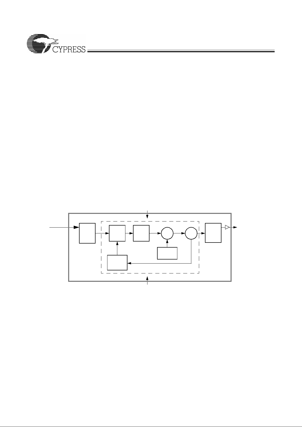
Functional Description
The W180 uses a phase-locked loop (PLL) to frequency modulate an input clock. The result is an output clock whose frequency is slo w ly swep t over a narrow band near the i nput signal. The basic circuit topology is shown in Figur e 1. The i nput
refer ence signa l is div ided b y Q and f e d to the phase detector.
A signal from the VCO is divided by P and fed back to the
phase detector also. The PLL will force the frequency of the
VCO output signal to change until the divided output signal
and the divided reference signal match at the phase detector
input. The output frequency is then equal to the ratio of P/Q
times the ref er ence fre quenc y. (Note: F or t he W180 t he outpu t
frequency is eq ual to the input frequency.) Th e unique feature
of the Spread Spect rum Fr equ ency Timi ng Gener ator is that a
modulating wa vef orm is supe rimposed at t he input to the VCO .
This causes the VCO output to be slowly swept across a predetermined frequency ban d.
Because the modulating frequency is typically 1000 times
slower than the fundamental clock, the spread spectrum process has little impact on system performance.
Frequency Selection With SSFTG
In Spread Spectrum Frequency Timing Generation, EMI reduction depends on the shape, modulation percentage, and
frequency of the modulating waveform. While the shape and
frequency of the modulating waveform are fixed for a given
frequency, the modulation percentage may be va ried .
Using frequency s elect bits (FS2:1 pins), the frequency range
can be set (see Table 2). Spread ing percentage is set with pin
SS% as shown in Table 1.
A larger spreading per centage improves EMI reduction. However, large spread percentages may either exceed system
maximum frequ ency ra tings o r lo wer the a v er age fr equency t o
a point where performance is affected. For these reasons,
spreading percentages options are provided.
Freq. Phase
Modulating
VCO
Post
CLKOUT
Detector
Charge
Pump
Waveform
DividersDivider
Feedback
Divider
PLL
GND
V
DD
Σ
Q
P
Clock Input
Reference Input (EMI suppressed)
Figure 1. Functional Block Diagram
Page 4

W180
4
Spread Spectrum Frequency Timing
Generation
The device generates a clock that is frequency modulated in
order to increase the bandwidth that it occu pies. By increas ing
the bandwidth of the fundamental and its harmonics, the amplitudes of the radiated electromagnetic emissions are reduced. This effect is depicted in Figure 2.
As shown in Figure 2, a harmonic of a modulated clock has a
much low er amplitude t han that of an un modulated si gnal. The
reduction in amplitude is dependent on the harmonic number
and the frequency deviation or spread. The equation for the
reduction is:
dB = 6.5 + 9*log
10
(P) + 9*log10(F)
Where P is the perce ntag e of de viati on an d F is the frequency
in MHz where the reduction is measured.
The output clock is modulated with a waveform depicted in
Figure 3. This waveform, as discussed in “Spread Spectrum
Clock Gener ation f or the Redu ct ion of Radiat ed Emiss ions” by
Bush, Fessler, and Hardin produces the maximum reduction
in the amplitude of radiat ed electro magnetic emis sions. Figure
3 details the Cypress spreading pattern. Cypress does offer
options with more spread and gr eater EMI reduction. Cont act
your local Sales representativ e for details on these devices.
SSFTG Typical Clock
Frequency Span (MHz)
Amplitude (dB)
Spread
Spectrum
Enabled
EMI Reduction
Spread
Spectrum
Non-
Frequency Span (MHz)
Down Spread
Amplitude (dB)
Center Spread
Figure 2. Clock Har monic with and without SSCG Modulat ion Frequenc y Domain Represent ation
MAX.
MIN.
10%
20%
30%
40%
50%
60%
70%
80%
90%
100%
10%
20%
30%
40%
50%
60%
70%
80%
90%
100%
FREQUENCY
Figure 3. Typical Modulation Prof ile
Page 5

W180
5
Absolute Maximum Ratings
Stresses greater than those listed in this table may cause permanent damage to the de vice . These represent a stress ratin g
only. Operation of the devi ce at these or any other conditions
above those specified in the operating sections of this specification is not implied. Maximum conditions for extended periods may affect reliability.
.
Parameter Description Rating Unit
V
DD
, V
IN
Voltage on any pin with respect to GND –0.5 to +7 .0 V
T
STG
Storage Temperature –65 to +150 °C
T
A
Operating Tempera tur e 0 to +70 °C
T
B
Ambient Temperature under Bias –55 to +125 °C
P
D
Power Dissi pation 0.5 W
DC Electr i cal C h ar acteristics
:
0°C < T
A
< 70°C, VDD = 3.3V ±5%
Parameter Description T est Condition Min. Typ. Max. Unit
I
DD
Supply Current 18 32 mA
t
ON
Po wer Up Time First locked clock cycle after Power
Good
5ms
V
IL
Input Low Voltage 0.8 V
V
IH
Input High Vol tage 2.4 V
V
OL
Output Low Voltage 0.4 V
V
OH
Output High Voltage 2.4 V
I
IL
Input Low Current Not e 1 –50 µA
I
IH
Input High Current Note 1 50 µA
I
OL
Output Low Current @ 0.4V, VDD = 3.3V 15 mA
I
OH
Output High Current @ 2.4V, VDD = 3.3V 15 mA
C
I
Input Capacitance 7pF
R
P
Input Pull-Up Resistor 500 kΩ
Z
OUT
Clock Output Imp edance 25 Ω
Note:
1. Inputs FS2:1& SS% have a pull-up resistor; Input SSON# has a pull-down resistor.
Page 6

W180
6
DC Electr i cal C h ar acteristics:
0°C < T
A
< 70°C, VDD = 5V ±10%
Parameter Description Test Condition Min. Typ. Max. Unit
I
DD
Supply Current 30 50 mA
t
ON
Power Up Time First locked clock cycle after
Power Good
5ms
V
IL
Input Low Voltage 0.15V
DD
V
V
IH
Input High Voltage 0.7V
DD
V
V
OL
Output Low Voltage 0.4 V
V
OH
Output High Voltage 2.4 V
I
IL
Input Low Current Note 2 –50 µA
I
IH
Input High Current Note 2 50 µA
I
OL
Output Low Current @ 0.4V, VDD = 5V 24 mA
I
OH
Output High Current @ 2.4V, VDD = 5V 24 mA
C
I
Input Capacitance 7pF
R
P
Input Pull-Up Resistor 500 kΩ
Z
OUT
Clock Output I mpedance 25 Ω
AC Electrical Characteristics:
TA = 0°C to +70°C, VDD = 3.3V ±5% or 5V±10%
Symbol Parameter T est Condition Min. Typ. Max. Unit.
f
IN
Input Frequency (-01) Input Clock, Note 3 8 28 MHz
f
OUT
Output Frequency (-01) Spread Off, Note 3 8 28 MHz
t
R
Output Rise Time 15-pF load 0.8V–2.4V 2 5 ns
t
F
Output Fall Time 15-pF load 2.4 –0.8V 2 5 ns
t
OD
Output Duty Cycle 15-pF load 40 60 %
t
ID
Input Duty Cycle 40 60 %
t
JCYC
Jitter, Cycle- to -C y cle 250 30 0 ps
Harmonic Reduction f
out
= 20 MHz, thir d harmonic
measured, ref erence board,
15-pF load
8dB
Notes:
2. Inputs FS1:2 have a pull-up resistor; Input SSON# has a pull-down resistor.
3. Frequency range listed for -01 version. See
Table 2
for frequency range of -02 and -03 versions.
Page 7

W180
7
Application Information
Recommended Circui t Configuration
For optimum performance in system applications the power
supply decoupli ng scheme sho wn in Figure 4 should be used .
V
DD
decoupling is important to both reduce phase jitter and
EMI radiation. The 0.1-µF decoupling capacitor should be
placed as close to the V
DD
pin as possible, otherwise the in-
creased trace inductance will negate its decoupling capability.
The 10-µF decoupling capacitor shown should be a tantalum
type. For further EMI protection, the V
DD
connection can be
made via a ferrite bead, as shown.
Recommended Board Layout
Figure 5 shows a recommended 2-layer board layout.
Document #: 38-00796-A
Figure 4. Recommended Circuit Configuration
GND
W180
8
7
6
5
1
2
3
4
C1
FB
C2
3.3V or 5V System Supply
10
µF Tantalum
0.1
µF
Clock
Xtal Connection or Reference Input
Xtal Connection or NC
Output
R1
Ordering Information
Ordering Code
Freq. Mask
Code
Package
Name
Packag e Type
W180 01, 02, 03
51. 52. 53
G 8-pin Plastic SOIC (150-mil)
Clock Output
High frequency supply decoupling
capacitor (0.1-
µF recommended).
Common supply low frequency
decoupling capacitor (10-
µF tantalu m
recommended).
FB
Ferrite Bead
C1 =
C2 =
Match valu e to lin e im pe da nce
R1 =
=
R1
C1
C2
G
G
FB
= Via To GND Plane
G
Xtal Co nnection or Reference Input
NC
G
Power Supply In put
(3.3V or 5V)
Figure 5. Recommended Board Layout (2-Layer Board)
Page 8

W180
© Cypress Semiconductor Corporation, 2000. The information contained herein is subject to change without notice. Cypress Semiconductor Corporation assumes no responsibility for the use
of any circuitry other than circuitry embodied in a Cypress Semiconductor product. Nor does it conv ey or imply any lice nse under patent or other rights. Cypress Semiconductor does not authorize
its products for use as critical components in life-support systems where a malfunction or failure may reasonably be expected to result in significant injury to the user. The inclusion of Cypress
Semiconductor products in life-support systems application implies that the manufacturer assumes all risk of such use and in doing so indemnifies Cypress Semiconductor against all charges.
Package Diagram
8-Pin Small Outline Integrated Circuit (SOIC, 150 mils)
 Loading...