

Page 1

VENTILATION, HEATER & AIR CONDITIONER
Revision: October 2006
2007 G35 Sedan
SECTION VTL
A
B
CONTENTS
FUNCTION DIAGNOSIS ...............................3
SWITCHES AND THEIR CONTROL FUNC-
TION ....................................................................
WITHOUT LEFT AND RIGHT VENTILATION TEM-
PERATURE SEPARATELY CONTROL SYSTEM ......
WITHOUT LEFT AND RIGHT VENTILATION
TEMPERATURE SEPARATELY CONTROL
SYSTEM : System Description .................................
WITH LEFT AND RIGHT VENTILATION TEMPER-
ATURE SEPARATELY CONTROL SYSTEM .............
WITH LEFT AND RIGHT VENTILATION TEMPERATURE SEPARATELY CONTROL SYSTEM
: System Description .................................................
AIR DISTRIBUTION ............................................ 5
System Description ...................................................5
PRECAUTION ...............................................6
PRECAUTIONS ...................................................6
Precaution for Supplemental Restrain t System
(SRS) "AIR BAG" and "SEAT BELT PRE-TEN-
SIONER" ...................................................................
Precaution Necessary for Steering Wheel Rota-
tion after Battery Disconnect .....................................
Precaution for Procedure without Cowl Top Cover ......6
Precautions For Xenon Headlamp Service ...............7
Working with HFC-134a (R-134a) .............................7
General Refrigerant Precaution ................................8
Refrigerant Connection .............................................8
Service Equipment ..................................................12
COMPRESSOR ..................................................15
General Precautions ...............................................15
FLUORESCENT LEAK DETECTOR .................16
General Precautions ...............................................16
PREPARATION ...........................................17
VENTILATION SYSTEM
PREPARATION .................................................17
Special Service Tool ................................................17
Commercial Service Tool ........................................19
3
3
3
3
3
6
6
Sealant or/and Lubricant . ... ... .... ..............................20
ON-VEHICLE MAINTENANCE ....................21
IN-CABIN MICROFILTER .................................21
Exploded View .........................................................21
Removal and Installation .........................................21
Replacement ...........................................................21
ON-VEHICLE REPAIR .................................23
PRESET SWITCH .............................................23
Exploded View .........................................................23
Removal and Installation .........................................23
AUTO AMP. .......................................................24
Exploded View .........................................................24
Removal and Installation .........................................24
AMBIENT SENSOR ..........................................25
Exploded View .........................................................25
Removal and Installation .........................................25
IN-VEHICLE SENSOR ......................................26
Exploded View .........................................................26
Removal and Installation .........................................26
SUNLOAD SENSOR .........................................27
Exploded View .........................................................27
Removal and Installation .........................................27
INTAKE SENSOR .............................................28
Exploded View .........................................................28
Removal and Installation .........................................29
BLOWER UNIT .................................................30
Exploded View .........................................................30
Removal and Installation .........................................30
BLOWER MOTOR ............................................32
C
D
E
F
G
H
VTL
J
K
L
M
N
O
P
VTL-1
Page 2

Exploded View ........ ... ... ... ... .... ................................ 32
Revision: October 2006
2007 G35 Sedan
Removal and Installation ........................................ 32
INTAKE DOOR MOTOR ....................................33
Exploded View ........ ... ... ... ... .... ................................ 33
Removal and Installation ........................................ 33
HEATER & COOLING UNIT ASSEMBLY ......... 34
Exploded View ........ ... ... ... ... .... ................................ 34
Removal and Installation ........................................ 35
MODE DOOR MOTOR ......................................38
Exploded View ........ ... ... ... ... .... ................................ 38
Removal and Installation ........................................ 39
AIR MIX DOOR MOTOR ....................................40
Exploded View ........ ... ... ... ... .... ................................ 40
Removal and Installation ........................................ 41
FRONT DEFROSTER NOZZLE, SIDE DEFROSTER NOZZLES AND VENTILATOR DUCT
: Removal and Installation .......................................
46
SIDE DEFROSTER DUCTS ...................................... 47
SIDE DEFROSTER DUCTS : Exploded View ........47
SIDE DEFROSTER DUCTS : Removal and Instal-
lation .......................................................................
48
REAR VENTILATOR GRILLE ...... ... ... ... ... .... ... ... ... ....48
REAR VENTILATOR GRILLE : Exploded View ...... 48
REAR VENTILATOR GRILLE : Removal and In-
stallation ........................... .......................................
48
REAR VENTILATOR DUCT 2 ................................... 48
REAR VENTILATOR DUCT 2 : Exploded View ......48
REAR VENTILATOR DUCT 2 : Removal and In-
stallation ........................... .......................................
49
HEATER CORE ................................................. 42
Exploded View ........ ... ... ... ... .... ................................ 42
Removal and Installation ........................................ 43
DUCTS AND GRILLES ...................................... 44
CENTER VENTILATOR GRILLES ........................... 44
CENTER VENTILATOR GRILLES : Exploded
View ................................. .......................................
CENTER VENTILATOR GRILLES : Removal and
Installation ..............................................................
SIDE VENTILATOR GRILLES .................................. 44
SIDE VENTILATOR GRILLES : Exploded View ..... 44
SIDE VENTILATOR GRILLES : Removal and In-
stallation .................................................................
FRONT DEFROSTER NOZZLE, SIDE DEFROST-
ER NOZZLES AND VENTILATOR DUCT ................
FRONT DEFROSTER NOZZLE, SIDE DEFROSTER NOZZLES AND VENTILATOR DUCT
: Exploded View ......................................................
44
44
45
45
45
FOOT GRILLES ........................................................49
FOOT GRILLES : Exploded View ...........................49
FOOT GRILLES : Removal and Installation ........... 50
FOOT DUCTS ............................................................50
FOOT DUCTS : Exploded View .............................. 50
FOOT DUCTS : Removal and Installation .............. 52
REAR FLOOR DUCT 1 (WITHOUT REAR VENTI-
LATOR) .....................................................................
52
REAR FLOOR DUCT 1 (WITHOUT REAR VENTI-
LATOR) : Exploded View ........................................
52
REAR FLOOR DUCT 1 (WITHOUT REAR VENTI-
LATOR) : Removal and Installation ........................
53
REAR FLOOR DUCT 1 & REAR VENTILATOR
DUCT 1(WITH REAR VENTILATOR) .......................
53
REAR FLOOR DUCT 1 & REAR VENTILATOR
DUCT 1(WITH REAR VENTILATOR) : Exploded
View ........................................................................
53
REAR FLOOR DUCT 1 & REAR VENTILATOR
DUCT 1(WITH REAR VENTILATOR) : Removal
and Installation ........................................................
54
VTL-2
Page 3
SWITCHES AND THEIR CONTROL FUNCTION
Revision: October 2006
2007 G35 Sedan
< FUNCTION DIAGNOSIS >
FUNCTION DIAGNOSIS
SWITCHES AND THEIR CONTROL FUNCTION
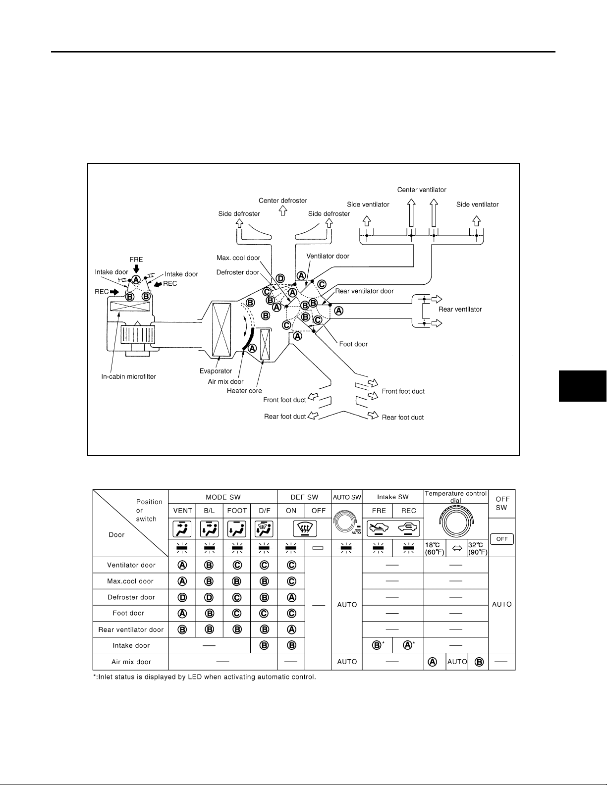
WITHOUT LEFT AND RIGHT VENTILATION TEMPERATURE SEPARATELY CONTROL SYSTEM
WITHOUT LEFT AND RIGHT VENTILATION TEMPERATURE SEPARATELY CONTROL SYSTEM : System Description
INFOID:0000000000959769
A
B
C
D
E
F
G
H
JSIIA0115GB
VTL
J
K
L
M
N
O
P
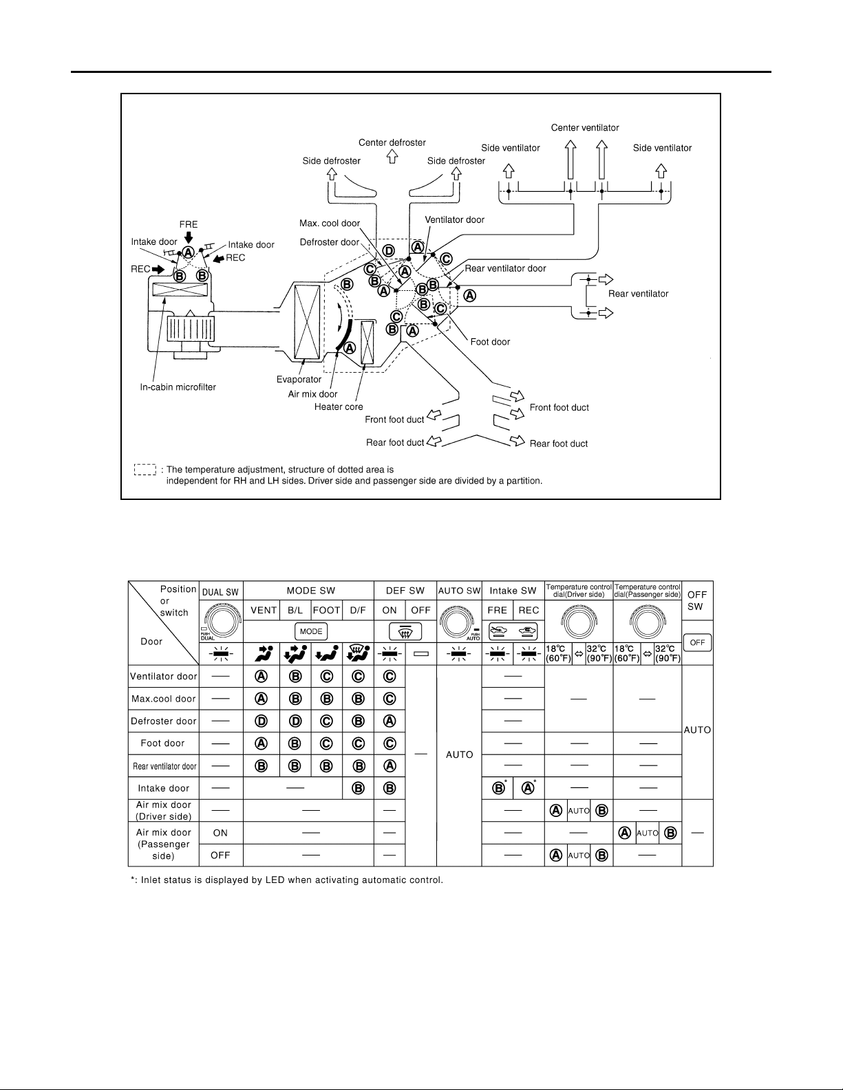
WITH LEFT AND RIGHT VENTILATION TEMPERATURE SEPARATELY CONTROL SYSTEM
WITH LEFT AND RIGHT VENTILATION TEMPERATURE SEPARATELY CONTROL
JSIIA0079GB
VTL-3
Page 4
SWITCHES AND THEIR CONTROL FUNCTION
Revision: October 2006
2007 G35 Sedan
< FUNCTION DIAGNOSIS >
SYSTEM : System Description
INFOID:0000000000959770
JSIIA0078GB
JSIIA0080GB
VTL-4
Page 5
< FUNCTION DIAGNOSIS >
Revision: October 2006
2007 G35 Sedan
AIR DISTRIBUTION
AIR DISTRIBUTION
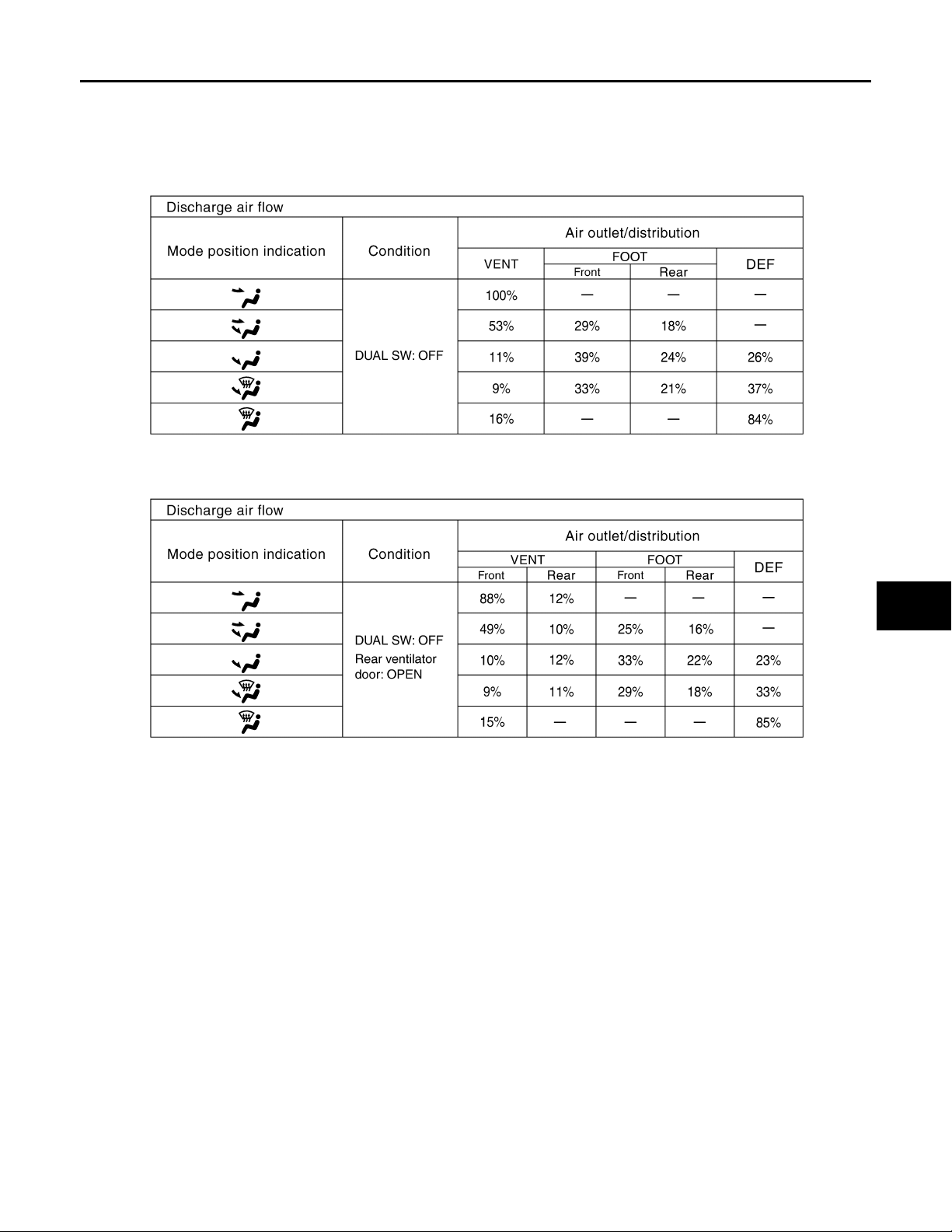
System Description INFOID:0000000000959771
Without rear ventilation
JSIIA0111GB
With rear ventilation
A
B
C
D
E
F
G
H
JSIIA0060GB
VTL
J
K
L
M
N
O
P
VTL-5
Page 6

PRECAUTIONS
Revision: October 2006
2007 G35 Sedan
< PRECAUTION >
PRECAUTION
PRECAUTIONS
Precaution for Supplemental Restraint System (SRS) "AIR BAG" and "SEAT BELT PRE-TENSIONER" INFOID:0000000000959772
The Supplemental Restraint System such as “AIR BAG” and “SEAT BELT PRE-TENSIONER”, used along
with a front seat belt, helps to reduce the risk or severity of injury to the driver and front passenger for certain
types of collision. This system includes seat belt switch inputs and dual stage front air bag modules. The SRS
system uses the seat belt switches to determine the front air bag deployment, and may only deploy one front
air bag, depending on the severity of a collision and whether the front occupants are belted or unbelted.
Information necessary to service the system safely is included in the SRS and SB section of this Service Manual.
WARNING:
• To avoid rendering the SRS inoperative, which could increase the risk of personal injury or death in
the event of a collision which would result in air bag inflation, all maintenance must be performed by
an authorized NISSAN/INFINITI dealer.
• Improper maintenance, including incorrect removal and installation of the SRS, can lead to personal
injury caused by unintentional activation of the system. For removal of Spiral Cable and Air Bag
Module, see the SRS section.
• Do not use electrical test equipment on any circuit related to the SRS unless instructed to in this
Service Manual. SRS wiring harnesses can be identified by yellow and/or orange harnesses or harness connectors.
Precaution Necessary for Steering Wheel Rotation after Battery Disconnect
INFOID:0000000000959773
NOTE:
• Before removing and installing any control units, first turn the push-button ignition switch to the LOCK position, then disconnect both battery cables.
• After finishing work, confirm that all control unit connectors are connected properly, then re-connect both
battery cables.
• Always use CONSULT-III to perform self-diagnosis as a part of each function inspection after finishing work.
If a DTC is detected, perform trouble diagnosis according to self-diagnosis results.
This vehicle is equipped with a push-button ignition switch and a steering lock unit.
If the battery is disconnected or discharged, the steering wheel will lock and cannot be turned.
If turning the steering wheel is required with the battery disconnected or discharged, follow the procedure
below before starting the repair operation.
OPERATION PROCEDURE
1. Connect both battery cables.
NOTE:
Supply power using jumper cables if battery is discharged.
2. Carry the Intelligent Key or insert it to the key slot and turn the push-button ignition switch to ACC position.
(At this time, the steering lock will be released.)
3. Disconnect both battery cables. The steering lock will remain released with both battery cables discon-
nected and the steering wheel can be turned.
4. Perform the necessary repair operation.
5. When the repair work is completed, re-connect both battery cables. With the brake pedal released, turn
the push-button ignition switch from ACC position to ON position, then to LOCK position. (The steering
wheel will lock when the push-button ignition switch is turned to LOCK position.)
6. Perform self-diagnosis check of all control units using CONSULT-III.
Precaution for Procedure without Cowl Top Cover INFOID:0000000000959774
VTL-6
Page 7
PRECAUTIONS
Revision: October 2006
2007 G35 Sedan
< PRECAUTION >
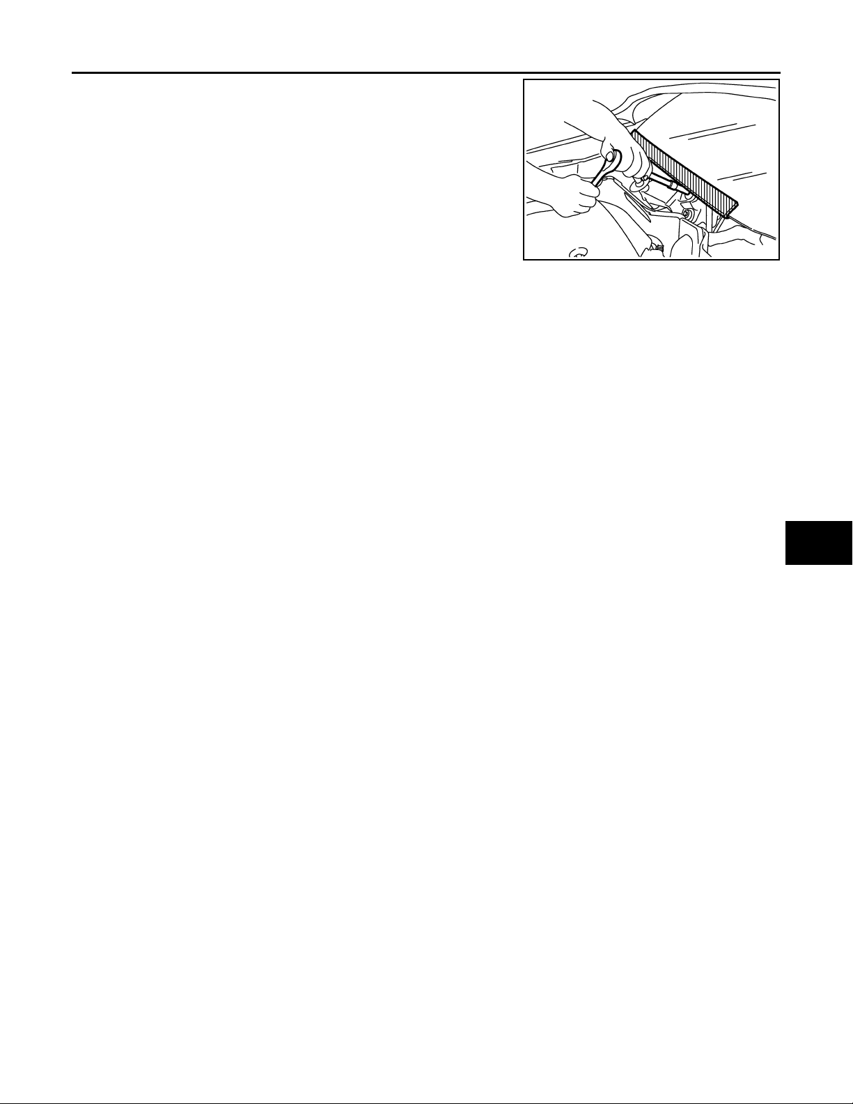
When performing the procedure after removing cowl top cover , cover
the lower end of windshield with urethane, etc.
PIIB3706J
Precautions For Xenon Headlamp Service INFOID:0000000000959775
A
B
C
D
WARNING:
Comply with the following warnings to prevent any serious accident.
• Disconnect the battery cable (negative terminal) or the power supply fuse before installing, removing, or touching the xenon headlamp (bulb included). The xenon headlamp contains high-voltage
generated parts.
• Never work with wet hands.
• Check the xenon headlamp ON-OFF status after assembling it to the vehicle. Never turn the xenon
headlamp ON in other conditions. Connect the power supply to the vehicle-side connector.
(Turning it ON outside the lamp case may cause fire or visual impairments.)
• Never touch the bulb glass immediately after turning it OFF. It is extremely hot.
CAUTION:
Comply with the following cautions to prevent any error and malfunction.
• Install the xenon bulb securely. (Insufficient bulb socket installation may melt the bulb, the connector, the housing, etc. by high-voltage leakage or corona discharge.)
• Never perform HID circuit inspection with a tester.
• Never touch the xenon bulb glass with hands. Never put oil and grease on it.
• Dispose of the used xenon bulb after packing it in thick vinyl without breaking it.
• Never wipe out dirt and contamination with organic solvent (thinner, gasoline, etc.).
Working with HFC-134a (R-134a) INFOID:0000000000959776
CAUTION:
• CFC-12 (R-12) refrigerant and HFC-134a (R-134a) refrigerant are not compatible. If the refrigerants
are mixed and compressor malfunction is likely to occur, refer to “CONTAMINATED REFRIGERANT”
below. To determine the purity of HFC-134a (R-134a) in the vehicle and recovery tank, use Refrigerant Recovery/Recycling Recharging equipment and Refrigerant Identifier.
• Use only specified lubricant for the HFC-134a (R-134a) A/C system and HFC-134a (R-134a) components. If lubricant other than that specified is used, compressor malfunction is likely to occur.
• The specified HFC-134a (R-134a) lubricant rapidly absorbs moisture from the atmosphere. The following handling precautions must be observed:
- When removing refrigerant components from a vehicle, immediately cap (seal) the component to
minimize the entry of moisture from the atmosphere.
- When installing refrigerant components to a vehicle, never remove the caps (unseal) until just before
connecting the components. Connect all refrigerant loop components as quickly as possible to minimize the entry of moisture into system.
- Only use the specified lubricant from a sealed container. Immediately reseal containers of lubricant.
Without proper sealing, lubricant will become moisture saturated and should not be used.
- Never allow lubricant (Nissan A/C System Oil Type S) to come in contact with styrene foam parts.
Damage may result.
CONTAMINATED REFRIGERANT
If a refrigerant other than pure HFC-134a (R-134a) is identified in a vehicle, take appropriate steps
shown below:
• Explain to the customer that environmental regulations prohibit the release of contaminated refrigerant into
the atmosphere.
• Explain that recovery of the contaminated refrigerant could damage service equipment and refrigerant supply.
E
F
G
H
VTL
J
K
L
M
N
O
P
VTL-7
Page 8

PRECAUTIONS
Revision: October 2006
2007 G35 Sedan
< PRECAUTION >
• Suggest the customer return the vehicle to the location of previous service where the contamination may
have occurred.
• In case of repairing, recover the refrigerant using only dedicated equipment and containers. Never
recover contaminated refrigerant into the existing service equipment. If the facility does not have dedicated recovery equipment, contact a local refrigerant product retailer for available service. This refrigerant
must be disposed of in accordance with all federal and local regulations. In addition, replacement of all
refrigerant system components on the vehicle is recommended.
• If the vehicle is within the warranty period, the air conditioner warranty is void. Please contact Nissan Customer Affairs for further assistance.
General Refrigerant Precaution INFOID:0000000000959777
WARNING:
• Avoid breathing A/C refrigerant and lubricant vapor or mist. Exposure may irritate eyes, nose and
throat. Remove HFC-134a (R-134a) from the A/C system, using certified service equipment meeting
requirements of SAE J-2210 [HFC-134a (R-134a) recycling equipment], or J-2209 [HFC-134a (R-134a)
recovery equipment]. If accidental system discharge occurs, ventilate work area before resuming
service. Additional health and safety information may be obtained from refrigerant and lubricant
manufacturers.
• Never release refrigerant into the air. Use approved recovery/recycling equipment to capture the
refrigerant every time an air conditioning system is discharged.
• Always wear eye and hand protection (goggles and gloves) when working with any refrigerant or air
conditioning system.
• Never store or heat refrigerant containers above 52°C (126°F).
• Never heat a refrigerant container with an open flame; if container warming is required, place the
bottom of the container in a warm pail of water.
• Never intentionally drop, puncture, or incinerate refrigerant containers.
• Keep refrigerant away from open flames: poisonous gas will be produced if refrigerant burns.
• Refrigerant will displace oxygen, therefore be certain to work in well ventilated areas to prevent suffocation.
• Never pressure test or leak test HFC-134a (R-134a) service equipment and/or vehicle air conditioning
systems with compressed air during repair. Some mixtures of air and HFC-134a (R-134a) have been
shown to be combustible at elevated pressures. These mixtures, if ignited, may cause injury or property damage. Additional health and safety information may be obtained from refrigerant manufacturers.
Refrigerant Connection INFOID:0000000000959778
A new type refrigerant connection has been introduced to all refrigerant lines except the following location.
• Expansion valve to evaporator
• Refrigerant pressure sensor to liquid tank
ABOUT ONE-TOUCH JOINT
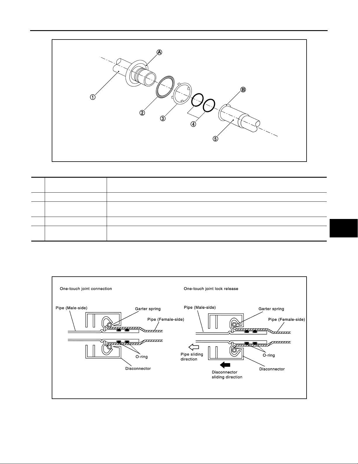
Description
• One-touch joints are pipe joints which do not require tools during piping connection.
• Unlike conventional connection methods using union nuts and flanges, controlling tightening torque at connection point is not necessary.
• When removing a pipe joint, use a disconnector.
VTL-8
Page 9
< PRECAUTION >
Revision: October 2006
2007 G35 Sedan
COMPONENT PARTS
PRECAUTIONS
A
B
C
D
E
RJIA4383J
FUNCTIONS OF COMPONENT PARTS
1 Pipe (Male-side)
2 Garter spring Anchors female-side piping (5).
3 Indicator ring
4 O-ring Seals connection point. (Not reusable)
5 Pipe (Female-side)
• Retains O-rings (4).
• Retains garter spring (2) in cage (A).
When connection is made properly, this is ejected from male-side piping (1). (This part is no longer
necessary after connection.)
• Seals connection by compressing O-rings (4).
• Anchors piping connection using flare (B) and garter spring (2).
NOTE:
• Garter spring (2) cannot be removed from cage (A) of male-side piping.
• Indicator ring (3) remains near piping connection point, however, this is not a malfunction. (This is to check
piping connection during factory assembly.)
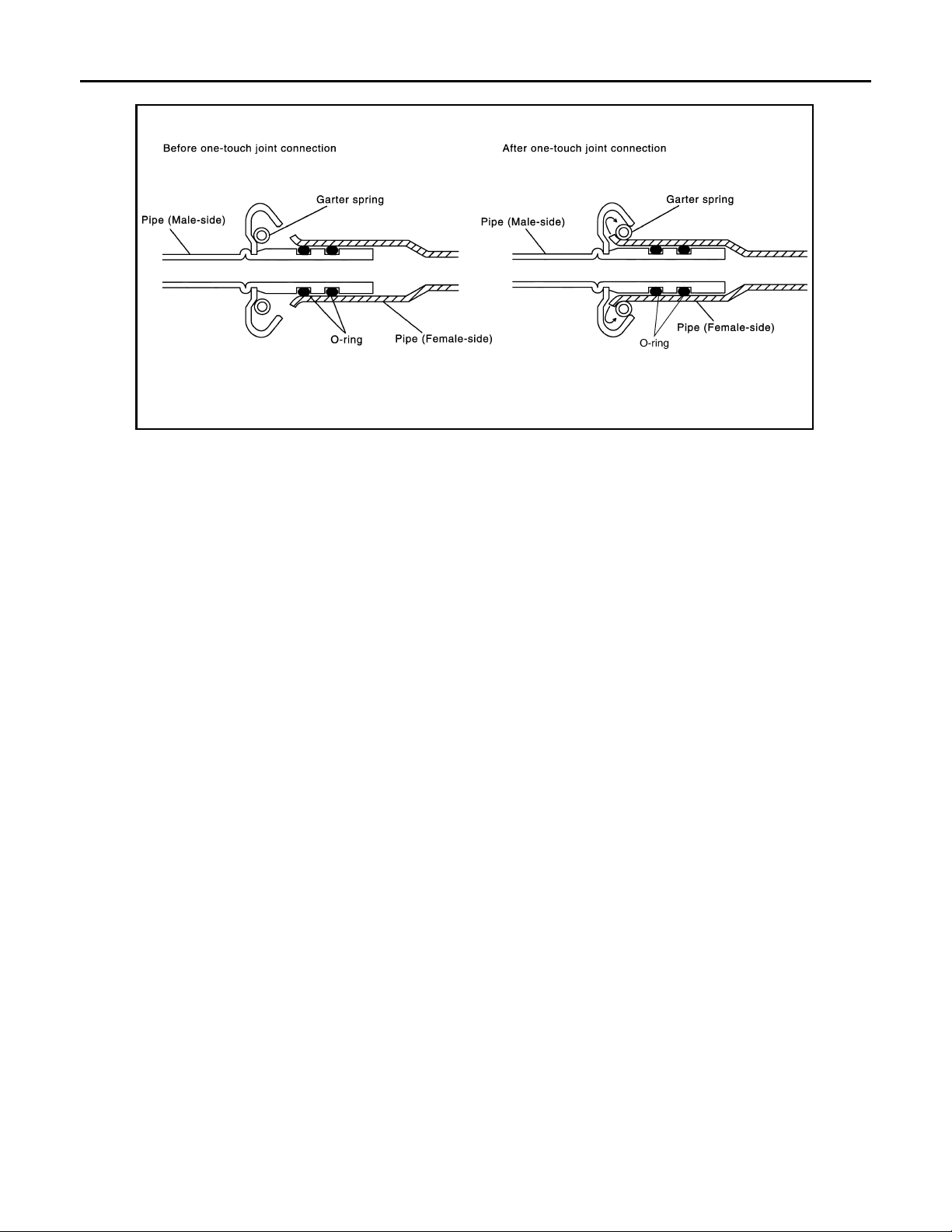
REMOVAL
F
G
H
VTL
J
K
L
M
1. Clean piping connection point, and set a disconnector.
2. Slide disconnector in axial direction of piping, and stretch garter spring with tapered point of disconnector.
3. Slide disconnector farther so that inside diameter of garter spring becomes larger than outside diameter of
female-side piping flare. Then male-side piping can be disconnected.
VTL-9
SJIA0106E
N
O
P
Page 10
PRECAUTIONS
Revision: October 2006
2007 G35 Sedan
< PRECAUTION >
INSTALLATION
SJIA0107E
1. Clean piping connection points, and insert male-side piping into female-side piping.
2. Push inserted male-side piping harder so that female-side piping flare stretches garter spring.
3. If inside diameter of garter spring becomes larger than outside diameter of female-side piping flare, garter
spring seats on flare. Then, it fits in between male-side piping cage and female-side piping flare to anchor
piping connection point.
NOTE:
When garter spring seats on flare, and fits in between male-side piping cage and female-side piping flare,
it clicks.
CAUTION:
• Female-side piping connection point is thin and easy to deform. Slowly insert the male-side pip-
ing straight in axial direction.
• Insert piping securely until a click is heard.
• After piping connection is completed, pull male-side piping by hand to make sure that connec-
tion does not come loose.
NOTE:
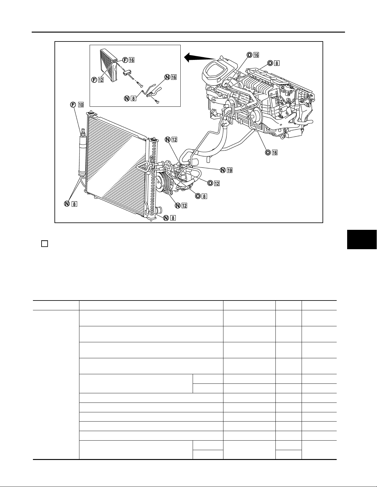
One-touch joint connection is used in points below.
• Low-pressure flexible hose to low-pressure pipe 2 (O-ring size: 16)
• Low-pressure pipe 1 to low-pressure pipe 2 (O-ring size: 16)
• High-pressure flexible hose to condenser pipe assembly (O-ring size: 12)
• High-pressure pipe 1 to high-pressure pipe 2 (O-ring size: 8)
• High-pressure pipe 1 to condenser pipe assembly (O-ring size: 8)
O-RING AND REFRIGERANT CONNECTION
VTL-10
Page 11
< PRECAUTION >
Revision: October 2006
2007 G35 Sedan
PRECAUTIONS
A
B
C
D
E
F
G
JSIIA0004ZZ
F. Former type refrigerant connection N. New type refrigerant connection O. One-touch joint
O-ring size
:
CAUTION:
The new and former refrigerant connections use different O-ring configurations. Never confuse Orings since they are not interchangeable. If a wrong O-ring is installed, refrigerant may leak at the connection.
O-Ring Part Numbers and Specifications
Connection type Piping connection point Part number QTY O -ring size
New
Low-pressure flexible hose to low-press ure pipe 2 (Onetouch joint)
High-pressure pipe 1 to high-pressure pipe 2 (One-touch
joint)
Condenser pipe assembly to high-pressure flexible hose
(One-touch joint)
Condenser pipe assembly to high-pressure pipe 1 (Onetouch joint)
Radiator & condenser assembly to condenser
pipe assembly
Low-pressure pipe 1 to low-pressure pipe 2 92473 N8210 1 16
Low-pressure pipe 1 to expansion valve 92473 N8210 1 16
High-pressure pipe 2 to expansion valve 92471 N8210 1 8
Compressor to low-pressure flexible hose 92474 N8210 1 19
Compressor to high-pressure flexible hose 92472 N8210 1 12
Liquid tank to radiator & condenser assembly
Inlet 92472 N8210 1 12
Outlet 92471 N8210 1 8
Inlet
Outlet 1
92473 N8221 2 16
92471 N8221 2 8
92472 N8221 2 12
92471 N8221 2 8
92471 N8210
1
8
H
VTL
J
K
L
M
N
O
P
VTL-11
Page 12
PRECAUTIONS
Revision: October 2006
2007 G35 Sedan
< PRECAUTION >
Connection type Piping connection point Part number QTY O-ring size
Refrigerant pressure sensor to liquid tank J2476 89956 1 10
Former
Expansion valve to evaporator
WARNING:
Make sure all refrigerant is discharged into the recycling equipment and the pressure in the system is
less than atmospheric pressure. Then gradually loosen the discharge side hose fitting and remove it.
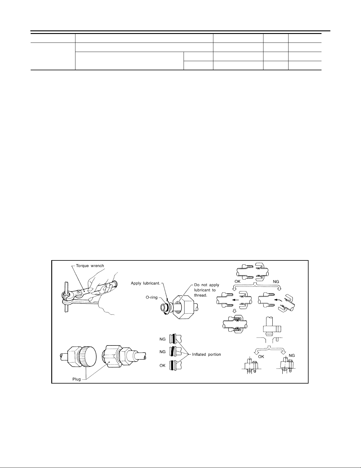
CAUTION:
When replacing or cleaning refrigerant cycle components, observe the following.
• When the compressor is removed, store it in the same way at it is when mounted on the car. Failure
to do so will cause lubricant to enter the low-pressure chamber.
• When connecting tubes, always use a torque wrench and a back-up wrench.
• After disconnecting tubes, immediately plug all openings to prevent entry of dust and moisture.
• When installing an air conditioner in the vehicle, connect the pipes at the final st age of the operation.
Never remove the seal caps of pipes and other components until just before required for connection.
• Allow components stored in cool areas to warm to working area temperature before removing seal
caps. This prevents condensation from forming inside A/C components.
• Thoroughly remove moisture from the refrigeration system before charging the refrigerant.
• Always replace used O-rings.
• When connecting tube, apply lubricant to circle of the O-rings shown in illustration. Be careful not to
apply lubricant to threaded portion.
Inlet 92475 71L00 1 12
Outlet 92475 72L00 1 16
Name : Nissan A/C System Oil
Type S
• O-ring must be closely attached to the groove portion of tube.
• When replacing the O-ring, be careful not to damage O-ring and tube.
• Connect tube until a click can be heard, then tighten the nut or bolt by hand. Make sure that the O-
ring is installed to tube correctly.
• After connecting line, perform leak test and make sure that there is no leakage from connections.
When the refrigerant leaking point is found, disconnect that line and replace the O-ring. Then tighten
connections of seal seat to the specified torque.
Service Equipment INFOID:0000000000959779
RECOVERY/RECYCLING EQUIPMENT
Be certain to follow the manufacturer’s instructions for machine operation and machine maintenance. Never
introduce any refrigerant other than that specified into the machine.
ELECTRICAL LEAK DETECTOR
Be certain to follow the manufacturer’s instructions for tester operation and tester maintenance.
RHA861F
VTL-12
Page 13
PRECAUTIONS
Revision: October 2006
2007 G35 Sedan
< PRECAUTION >
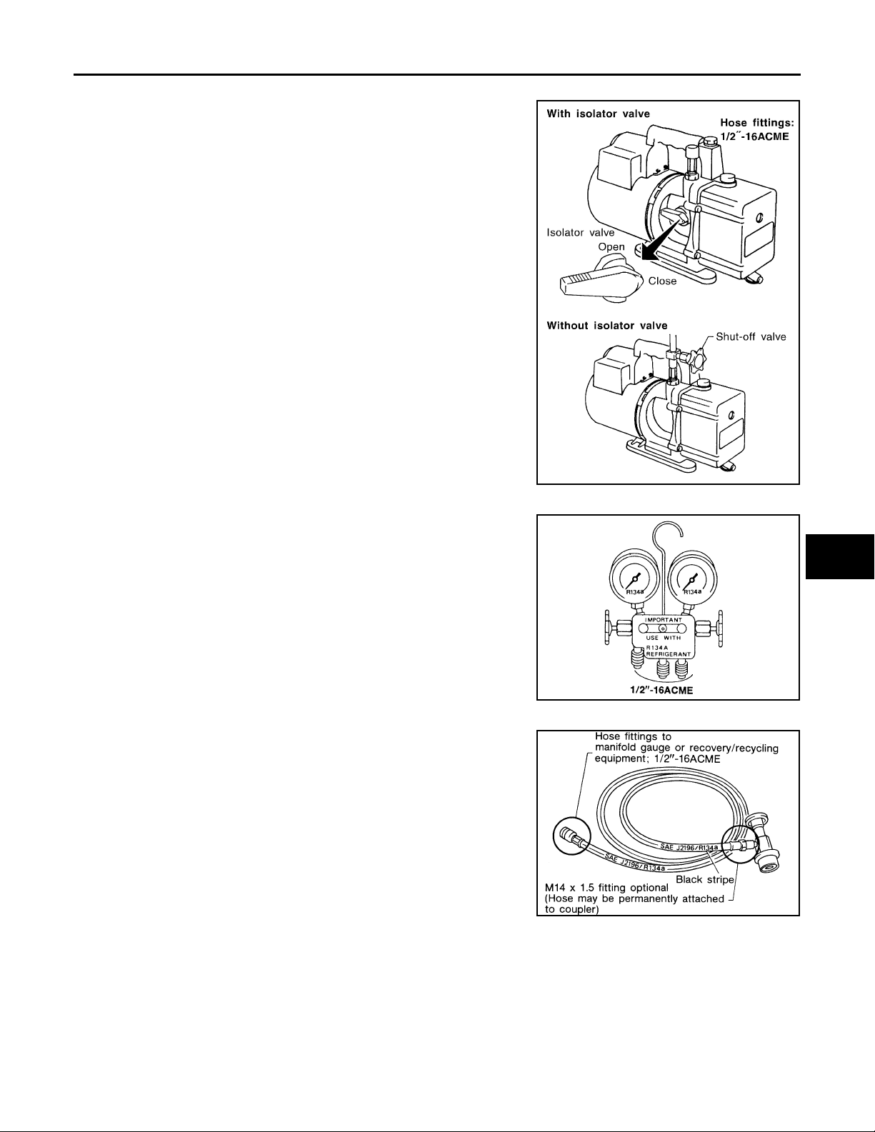
VACUUM PUMP
The lubricant contained inside the vacuum pump is not compatible
with the specified lubricant for HFC-134a (R-134a) A/C systems.
The vent side of the vacuum pump is exposed to atmospheric pressure. So the vacuum pump lubricant may migrate out of the pump
into the service hose. This is possible when the pump is switched off
after evacuation (vacuuming) and hose is connected to it.
To prevent this migration, use a manual valve placed near the hoseto-pump connection, as follows.
• Usually vacuum pumps have a manual isolator valve as part of the
pump. Close this valve to isolate the service hose from the pump.
• For pumps without an isolator, use a hose equipped with a manual
shut-off valve near the pump end. Close the valve to isolate the
hose from the pump.
• If the hose has an automatic shut-off valve, disconnect the hose
from the pump. As long as the hose is connected, the valve is open
and lubricating oil may migrate.
Some one-way valves open when vacuum is applied and close
under no vacuum condition. Such valves may restrict the pump’s
ability to pull a deep vacuum and are not recommended.
A
B
C
D
E
F
G
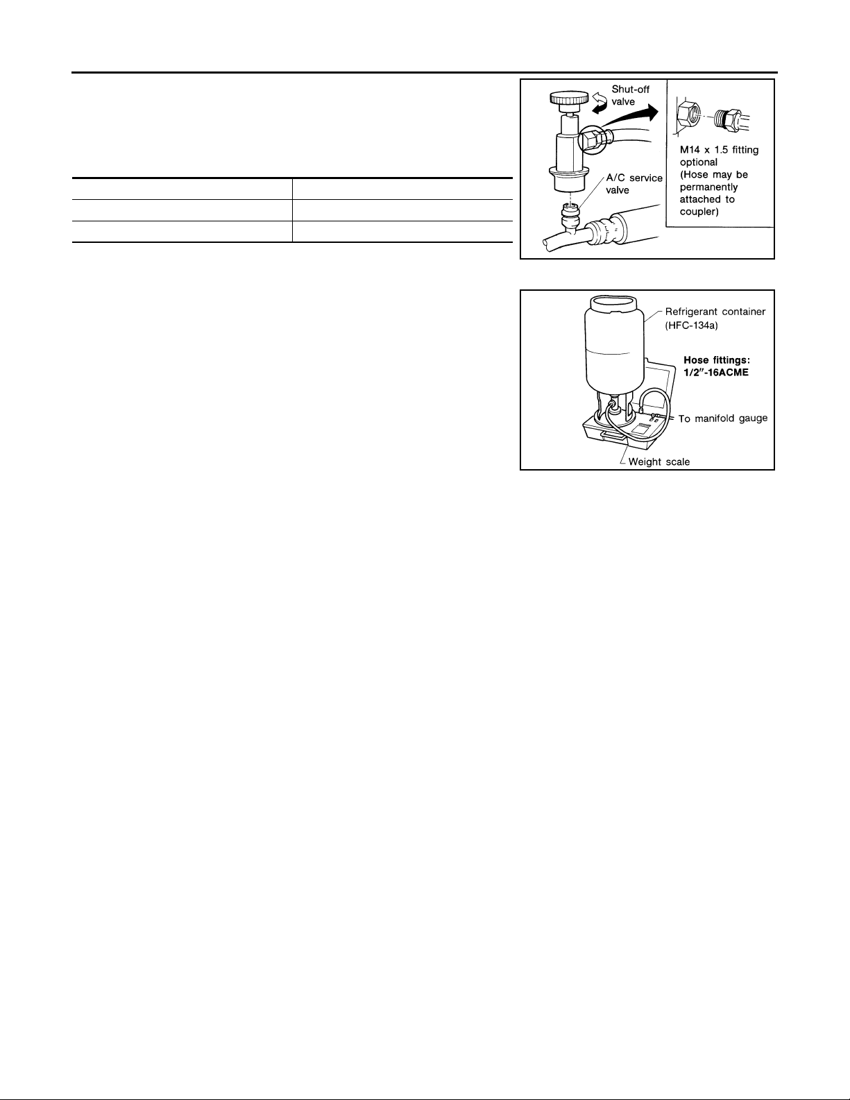
MANIFOLD GAUGE SET
Be certain that the gauge face indicates HFC-134a or R-134a. Be
sure the gauge set has 1/2″-16 ACME threaded connections for service hoses. Confirm the set has been used only with refrigerant
HFC-134a (R-134a) and specified lubricants.
SERVICE HOSES
Be certain that the service hoses display the markings described
(colored hose with black stripe). All hoses must include positive shutoff devices (either manual or automatic) near the end of the hoses
opposite to the manifold gauge.
RHA270DA
H
VTL
J
K
SHA533D
L
M
N
SERVICE COUPLERS
VTL-13
RHA272D
O
P
Page 14
PRECAUTIONS
Revision: October 2006
2007 G35 Sedan
< PRECAUTION >
Never attempt to connect HFC-134a (R-134a) service couplers to a
CFC-12 (R-12) A/C system. The HFC-134a (R-134a) couplers will
not properly connect to the CFC-12 (R-12) system. However, if an
improper connection is attempted, discharging and contamination
may occur.
Shut-off valve rotation A/C service valve
Clockwise Open
Counterclockwise Close
REFRIGERANT WEIGHT SCALE
Verify that no refrigerant other than HFC-134a (R-134a) and specified lubricants have been used with the scale. If the scale controls
refrigerant flow electronically, the hose fitting must be 1/2″-16
ACME.
RHA273D
RHA274D
CHARGING CYLINDER
Using a charging cylinder is not recommended. Refrigerant may be vented into air from cylinder’s top valve
when filling the cylinder with refrigerant. Also, the accuracy of the cylinder is generally less than that of an
electronic scale or of quality recycle/recharge equipment.
VTL-14
Page 15

< PRECAUTION >
Revision: October 2006
2007 G35 Sedan
COMPRESSOR
COMPRESSOR
General Precautions INFOID:0000000000959780
CAUTION:
• Plug all openings to prevent moisture and foreign matter from entering.
• When the compressor is removed, store it in the same way at it is when mounted on the car.
• When replacing or repairing compressor, follow “Maintenance of Lubricant Quantity in Compressor”
exactly. Refer to HA-30, "
• Keep friction surfaces between clutch and pulley clean. If the surface is contaminated with lubricant,
wipe it off by using a clean waste cloth moistened with thinner.
• After compressor service operation, turn the compressor shaft by hand more than five turns in both
directions. This will equally distribute lubricant inside the compressor. After the compressor is
installed, let the engine idle and operate the compressor for one hour.
• After replacing the compressor magnet clutch, apply voltage to the new one and check for normal
operation.
Adjustment".
A
B
C
D
E
F
G
H
VTL
J
K
L
M
N
O
P
VTL-15
Page 16

FLUORESCENT LEAK DETECTOR
Revision: October 2006
2007 G35 Sedan
< PRECAUTION >
FLUORESCENT LEAK DETECTOR
General Precautions INFOID:0000000000959781
CAUTION:
• The A/C system contains a fluorescent leak detection dye used for locating refrigerant leaks. An
ultraviolet (UV) lamp is required to illuminate the dye when inspecting for leaks.
• Always wear fluorescence enhancing UV safety goggles to protect your eyes and enhance the visibility of the fluorescent dye.
• The fluorescent dye leak detector is not a replacement for an electrical leak detector (SST: J-41995).
The fluorescent dye leak detector should be used in conjunction with an electrical leak detector
(SST: J-41995) to pin-point refrigerant leaks.
• For the purpose of safety and customer’s satisfaction, read and follow all manufacture’s operating
instructions and precautions prior to performing the work.
• A compressor shaft seal should not necessarily be repaired because of dye seepage. The compressor shaft seal should only be repaired after confirming the leak with an electrical leak detector (SST:
J-41995).
• Always remove any remaining dye from the leak area after repairs are completed to avoid a misdiagnosis during a future service.
• Never allow dye to come into contact with painted body panels or interior components. If dye is
spilled, clean immediately with the approved dye cleaner. Fluorescent dye left on a surface for an
extended period of time cannot be removed.
• Never spray the fluorescent dye cleaning agent on hot surfaces (engine exhaust manifold, etc.).
• Never use more than one refrigerant dye bottle (1/4 ounce /7.4 cc) per A/C system.
• Leak detection dyes for HFC-134a (R-134a) and CFC-12 (R-12) A/C systems are different. Never use
HFC-134a (R-134a) leak detection dye in CFC-12 (R-12) A/C system, or CFC-12 (R-12) leak detection
dye in HFC-134a (R-134a) A/C system, or A/C system damage may result.
• The fluorescent properties of the dye will remain for three years or a little over unless a compressor
malfunction occurs.
IDENTIFICATION
NOTE:
Vehicles with factory installed fluorescent dye have a green label.
Vehicles without factory installed fluorescent dye have a blue label.
IDENTIFICATION LABEL FOR VEHICLE
Vehicles with factory installed fluorescent dye have the identification label on the front side of hood.
VTL-16
Page 17
< PREPARATION >
Revision: October 2006
2007 G35 Sedan
PREPARATION
PREPARATION
PREPARATION
Special Service Tool INFOID:0000000000959782
The actual shapes of Kent-Moore tools may differ from those of special service tools illustrated here.
HFC-134a (R-134a) Service Tool and Equipment
• Never mix HFC-134a (R-134a) refrigerant and/or its specified lubricant with CFC-12 (R-12) refrigerant and/
or its lubricant.
• Separate and non-interchangeable service equipment must be used for handling each type of refrigerant/
lubricant.
• Refrigerant container fittings, service hose fittings and service equipment fittings (equipment which handles
refrigerant and/or lubricant) are different between CFC-12 (R-12) and HFC-134a (R-134a). This is to avoid
mixed use of the refrigerants/lubricant.
• Never use adapters that convert one size fitting to another: refrigerant/lubricant contamination occurs and
compressor malfunction may result.
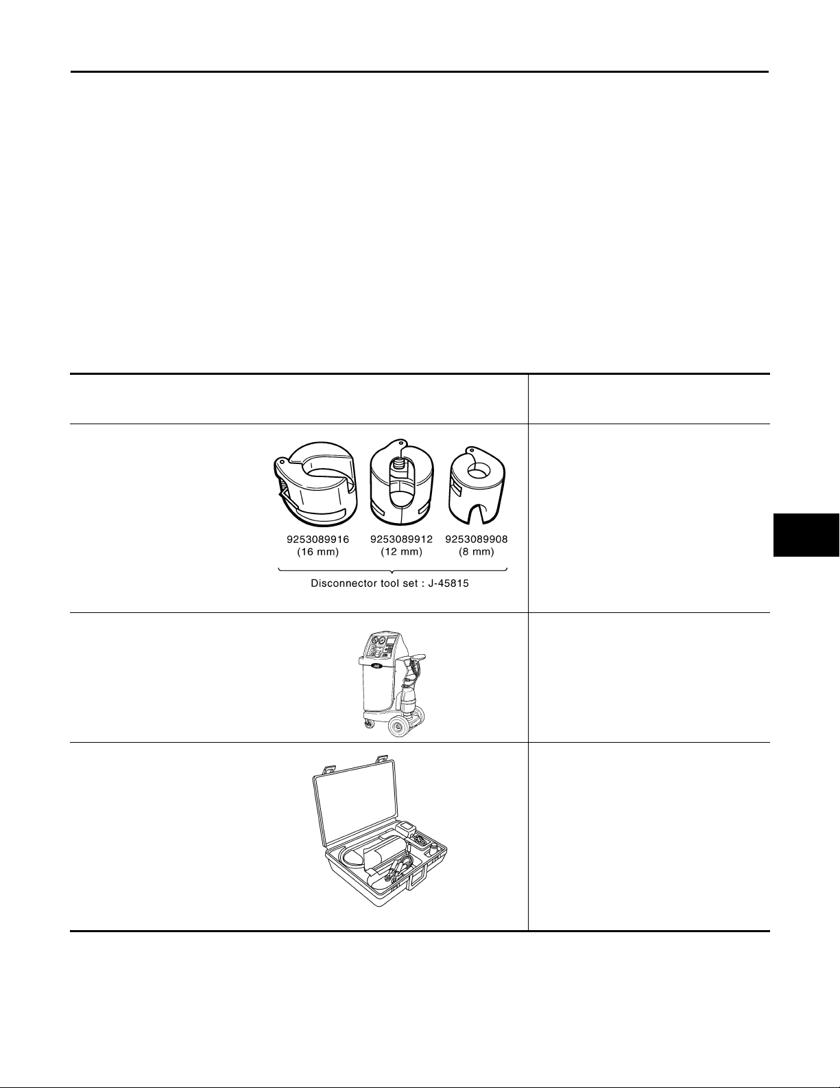
Tool number
9253089908 (for high-pressure
pipe 1)
(-)
9253089912 (for high-pressure
flexible hose)
(-)
9253089916 (for low-pressure
pipe 2 and low-pressure flexib le
hose)
(-)
Disconnector tool set
(J-45815)
(Kent-Moore No.)
Tool name
Disconnect one-touch joint connection
SJIA1274E
Description
A
B
C
D
E
F
G
H
VTL
J
(ACR2005-NI)
ACR5 A/C Service Center
(J-41995)
Electrical leak detector
WJIA0293E
AHA281A
K
Function: Refrigerant recovery, recycling
and recharging
L
M
N
Power supply:
DC 12 V (Battery terminal)
O
P
VTL-17
Page 18
< PREPARATION >
Revision: October 2006
2007 G35 Sedan
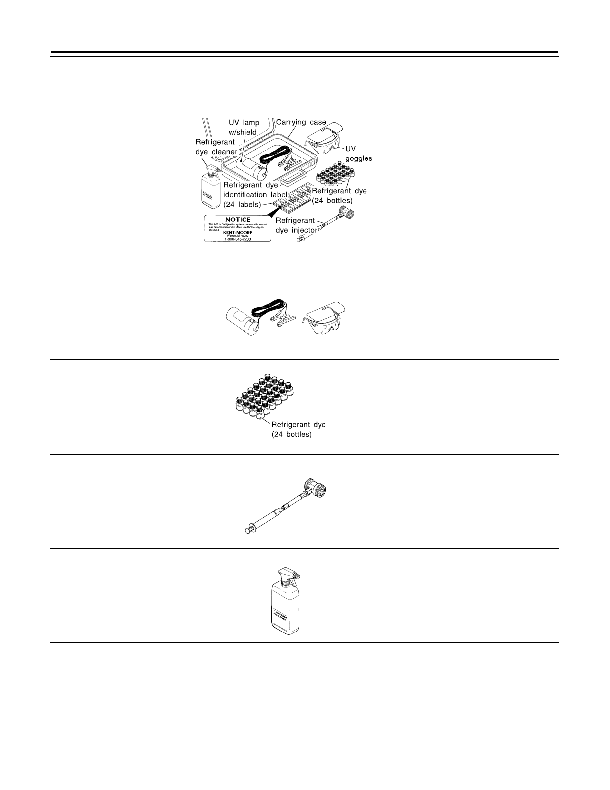
(J-43926)
Refrigerant dye leak detection
kit
Kit includes:
(J-42220)
UV lamp and UV safety goggles
(J-41459)
HFC-134a (R-134a) dye injector
Use with J-41447, 1/4 ounce
bottle
(J-41447)
HFC-134a (R-134a) fluorescent
leak detection dye
(Box of 24, 1/4 ounce bottles)
(J-43872)
Refrigerant dye cleaner
(J-42220)
UV lamp and UV safety goggles
Tool number
(Kent-Moore No.)
Tool name
PREPARATION
Description
Power supply:
DC 12 V (Battery terminal)
ZHA200H
Power supply:
DC 12 V (Battery terminal)
For checking refrigerant leak when fluorescent dye is installed in A/C system
Includes:
UV lamp and UV safety goggles
SHA438F
(J-41447)
HFC-134a (R-134a) fluorescent
leak detection dye
(Box of 24, 1/4 ounce bottles)
(J-41459)
HFC-134a (R-134a) dye injector
Use with J-41447, 1/4 ounce
bottle
(J-43872)
Refrigerant dye cleaner
Application:
For HFC-134a (R-134a) PAG oil
Container:
1/4 ounce (7.4 cc) bottle
(Includes self-adhesive dye identification
labels for affixing to vehicle after charging
system with dye.)
SHA439F
For injecting 1/4 ounce of fluorescent leak
detection dye into A/C system
SHA440F
For cleaning dye spills
SHA441F
VTL-18
Page 19
< PREPARATION >
Revision: October 2006
2007 G35 Sedan
PREPARATION
(J-39183)
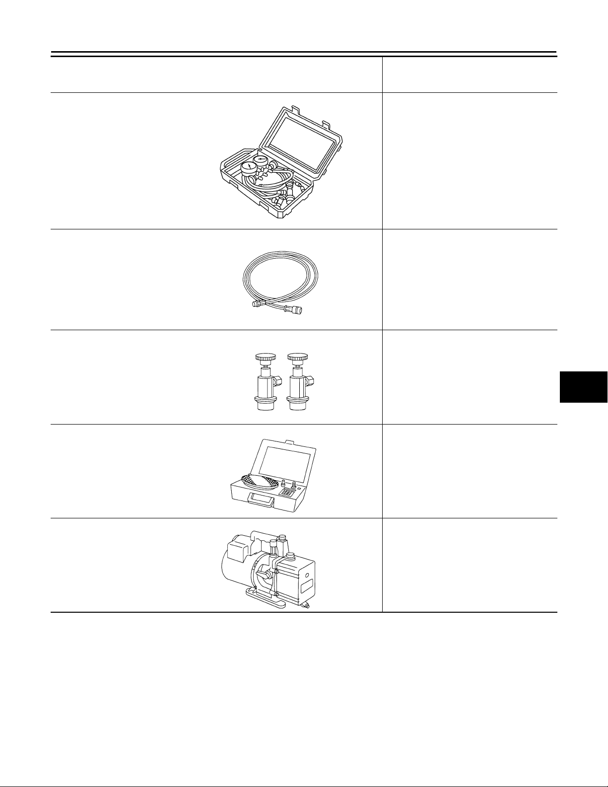
Manifold gauge set (with hoses
and couplers)
Service hoses
• High-pressure side hose
(J-39501-72)
• Low-pressure side hose
(J-39502-72)
• Utility hose
(J-39476-72)
Service couplers
• High-pressure side coupler
(J-39500-20)
• Low-pressure side coupler
(J-39500-24)
Tool number
(Kent-Moore No.)
Tool name
S-NT201
RJIA0196E
Description
Identification:
• The gauge face indicates HFC-134a (R134a).
Fitting size: Thread size
″
•1/2
-16 ACME
Hose color:
• Low-pressure side hose: Blue with blac k
stripe
• High-pressure side hose: Red with b lack
stripe
• Utility hose: Yellow with black stripe or
green with black stripe
Hose fitting to gauge:
″
•1/2
-16 ACME
Hose fitting to service hose:
M14 x 1.5 fitting is optional or perma nently
attached.
A
B
C
D
E
F
G
H
VTL
S-NT202
(J-39650)
Refrigerant weight scale
S-NT200
(J-39649)
Vacuum pump
(Including the isolator valve)
S-NT203
For measuring of refrigerant
Fitting size: Thread size
″
1/2
-16 ACME
Capacity:
• Air displacement: 4 CFM
• Micron rating: 20 microns
• Oil capacity: 482 g (17 oz.)
Fitting size: Thread size
″
•1/2
-16 ACME
Commercial Service Tool INFOID:0000000000959783
J
K
L
M
N
O
P
VTL-19
Page 20
< PREPARATION >
Revision: October 2006
2007 G35 Sedan
PREPARATION
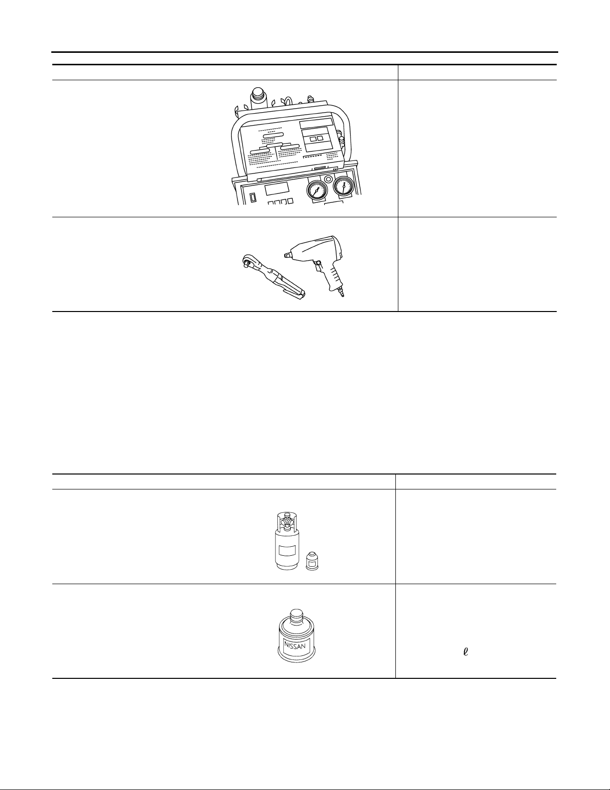
Tool name Description
Refrigerant identifier equipment
RJIA0197E
Power tool For loosening bolts and nuts
PBIC0190E
Sealant or/and Lubricant
Checking for refrigerant purity and
system contamination
INFOID:0000000000959784
HFC-134a (R-134a) Service Tool and Equipment
• Never mix HFC-134a (R-134a) refrigerant and/or its specified lubricant with CFC-12 (R-12) refrigerant and/
or its lubricant.
• Separate and non-interchangeable service equipment must be used for handling each type of refrigerant/
lubricant.
• Refrigerant container fittings, service hose fittings and service equipment fittings (equipment which handles
refrigerant and/or lubricant) are different between CFC-12 (R-12) and HFC-134a (R-134a). This is to avoid
mixed use of the refrigerants/lubricant.
• Never use adapters that convert one size fitting to another: refrigerant/lubricant contamination occurs and
compressor malfunction may result.
HFC-134a (R-134a) refrigerant
Nissan A/C System Oil Type S
(DH-PS)
Tool name Description
Container color: Light blue
Container marking: HFC-134a (R134a)
S-NT196
S-NT197
Fitting size: Thread size
• Large container 1/2
Type: Polyalkylene glycol oil (PAG),
type S (DH-PS)
Application:
HFC-134a (R-134a) swash plate compressors (Nissan only)
Capacity: 40 m (1.4 US fl oz., 1.4
Imp fl oz.)
″
-16 ACME
VTL-20
Page 21
< ON-VEHICLE MAINTENANCE >
Revision: October 2006
2007 G35 Sedan
IN-CABIN MICROFILTER
ON-VEHICLE MAINTENANCE
IN-CABIN MICROFILTER
Exploded View INFOID:0000000000959785
A
B
C
D
E
F
G
H
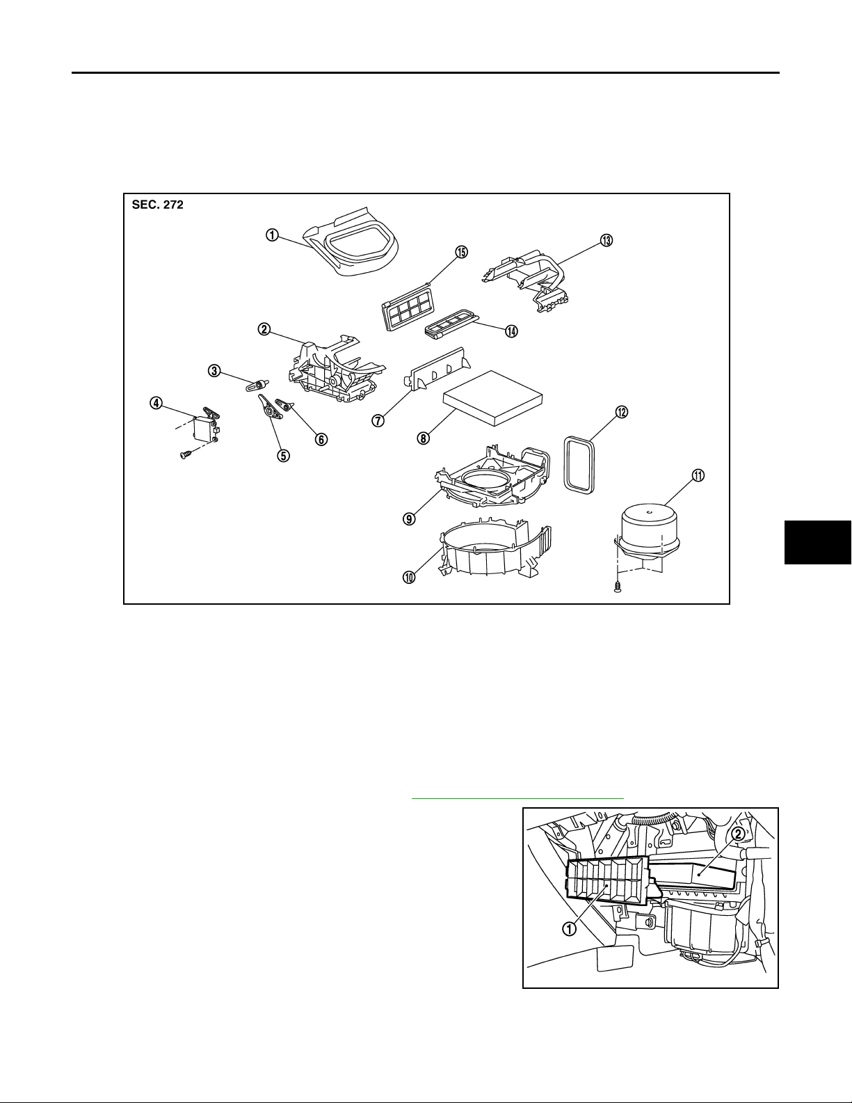
JSIIA0009GB
1. Adapter 2. Intake box (right) 3. Intake door lever 2
4. Intake door motor 5. Intake door link 6. Intake door lever 1
7. Filter cover 8. In-cabin microfilter 9. Intake upper case
10. Intake lower case 11. Blower moto r assembly 12. Seal
13. Intake box (left) 14. Intake door 1 15. Intake door 2
Removal and Installation INFOID:0000000000959786
REMOVAL
1. Remove instrument assist lower panel. Refer to IP-12, "Removal and Installation".
2. Remove filter cover (1), and then remove in-cabin microfilter (2).
VTL
J
K
L
M
N
O
P
INSTALLATION
Installation is basically the reverse order of removal.
Replacement INFOID:0000000000959787
JSIIA0034ZZ
VTL-21
Page 22

IN-CABIN MICROFILTER
Revision: October 2006
2007 G35 Sedan
< ON-VEHICLE MAINTENANCE >
Replace in-cabin microfilter.
Refer to MA-6, "
When replacing filter, affix a caution label inside the glove box.
Schedule 1" and MA-8, "Schedule 2".
VTL-22
Page 23
< ON-VEHICLE REPAIR >
Revision: October 2006
2007 G35 Sedan
PRESET SWITCH
ON-VEHICLE REPAIR
PRESET SWITCH
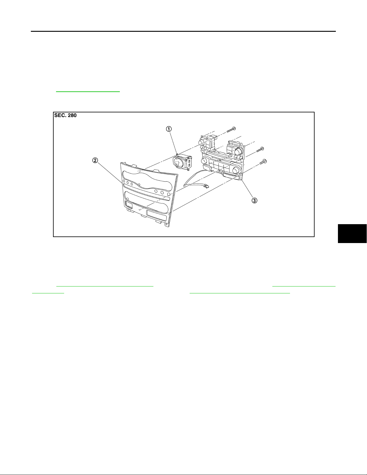
Exploded View INFOID:0000000000959788
REMOVAL
Refer to IP-11, "Exploded View".
DISASSEMBLY
A
B
C
D
E
F
G
H
JSNIA0107ZZ
1. Clock 2. Cluster lid C 3. Preset switch
Removal and Installation INFOID:0000000000959789
REMOVAL
Refer to AV-120, "Removal and Installation" (BASE AUDIO WITHOUT NAVIGATION), AV-305, "Removal and
Installation" (BOSE AUDIO WITHOUT NAVIGATION), AV-542, "Removal and Installation" (BOSE AUDIO
WITH NAVIGATION).
INSTALLATION
Installation is basically the reverse order of removal.
VTL
J
K
L
M
N
O
P
VTL-23
Page 24
AUTO AMP.
Revision: October 2006
2007 G35 Sedan
< ON-VEHICLE REPAIR >
AUTO AMP.
Exploded View INFOID:0000000000959790
REMOVAL
Refer to IP-11, "Exploded View".
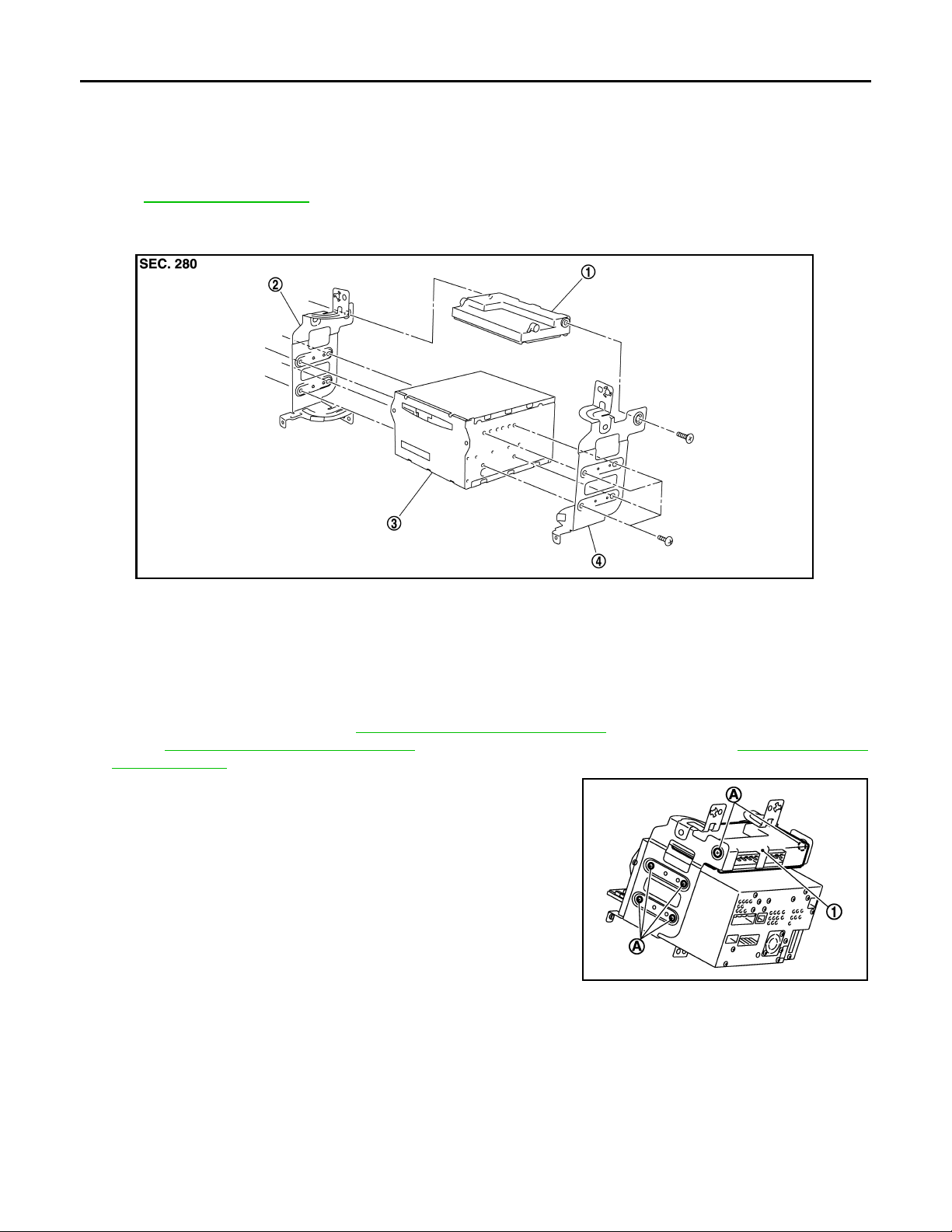
DISASSEMBLY
JSNIA0113ZZ
1. Unified meter and A/C amp. 2. Bracket LH 3. AV control unit
4. Bracket RH
Removal and Installation INFOID:0000000000959791
REMOVAL
1. Remove AV control unit. Refer to AV-111, "Removal and Installation" (BASE AUDIO WITHOUT NAVIGA-
TION), AV-292, "
and Installation" (BOSE AUDIO WITH NAVIGATION).
2. Remove mounting screws (A), and then remove unified meter
and A/C amp. (1).
INSTALLATION
Installation is basically the reverse order of removal.
Removal and Installation" (BOSE AUDIO WITHOUT NAVIGATION) or AV-530, "Removal
JSIIA0015ZZ
VTL-24
Page 25
< ON-VEHICLE REPAIR >
Revision: October 2006
2007 G35 Sedan
AMBIENT SENSOR
AMBIENT SENSOR
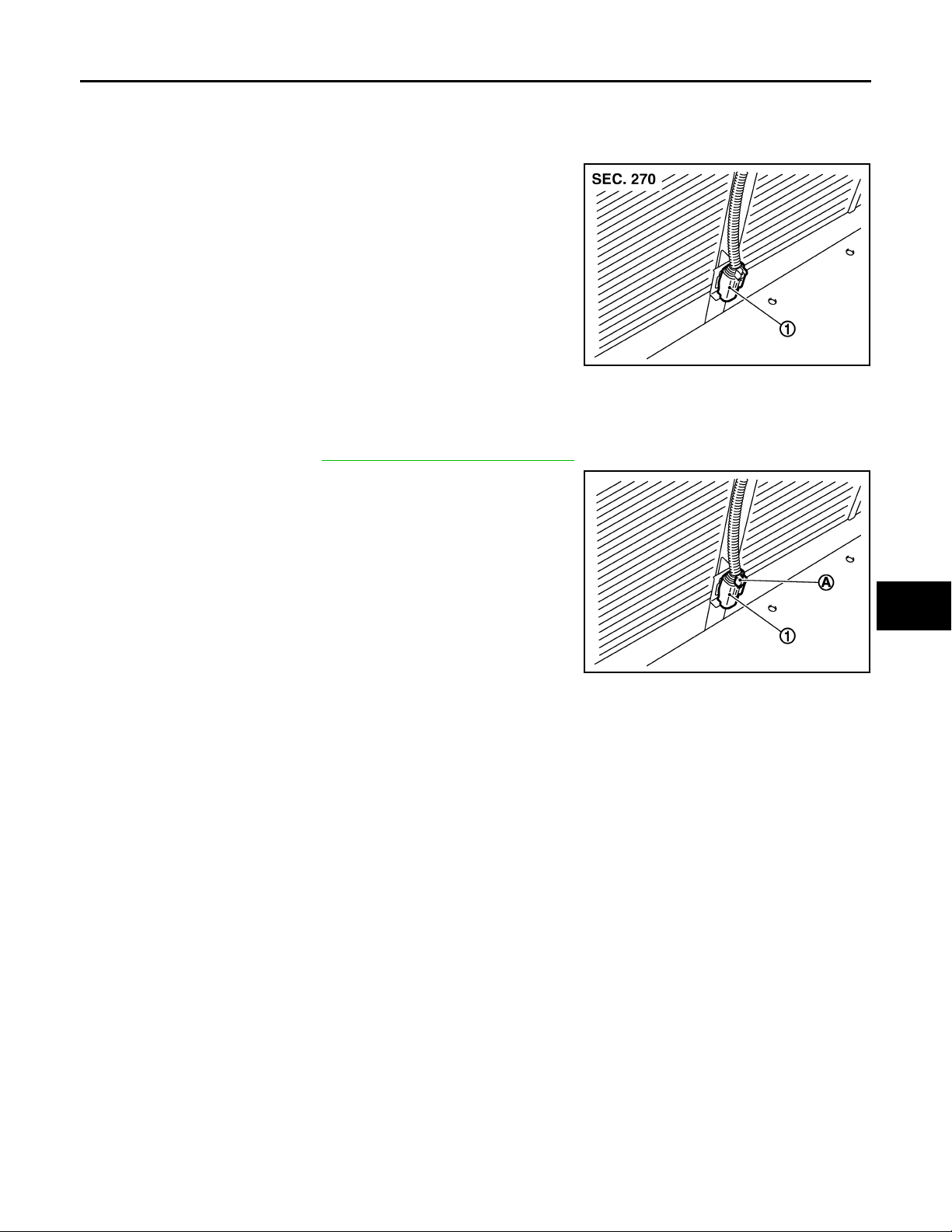
Exploded View INFOID:0000000000959792
1. Ambient sensor
JSIIA0046ZZ
Removal and Installation INFOID:0000000000959793
REMOVAL
1. Remove front grille. Refer to EXT-16, "Removal and Installation".
2. Disconnect ambient sensor connector (A), and then remove
ambient sensor (1).
A
B
C
D
E
F
G
H
INSTALLATION
Installation is basically the reverse order of removal.
JSIIA0121ZZ
VTL
J
K
L
M
N
O
P
VTL-25
Page 26
IN-VEHICLE SENSOR
Revision: October 2006
2007 G35 Sedan
< ON-VEHICLE REPAIR >
IN-VEHICLE SENSOR
Exploded View INFOID:0000000000959794
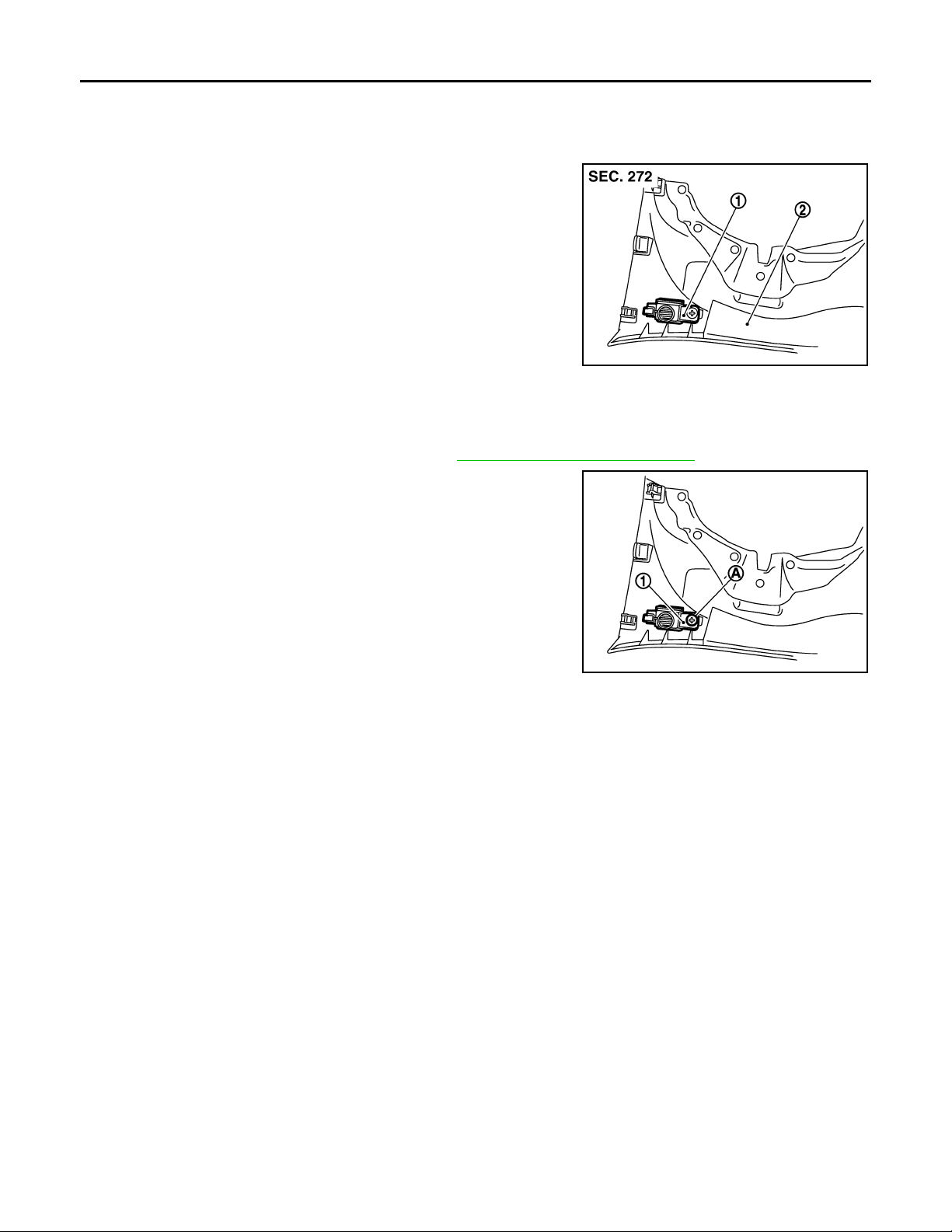
1. In-vehicle sensor
2. instrument driver lower panel
JSIIA0126ZZ
Removal and Installation INFOID:0000000000959795
REMOVAL
1. Remove instrument driver lower panel. Refer to IP-12, "Removal and Installation".
2. Remove mounting screw (A), and then remove in-vehicle sensor
(1).
INSTALLATION
Installation is basically the reverse order of removal.
JSIIA0032ZZ
VTL-26
Page 27
< ON-VEHICLE REPAIR >
Revision: October 2006
2007 G35 Sedan
SUNLOAD SENSOR
SUNLOAD SENSOR
Exploded View INFOID:0000000000959796
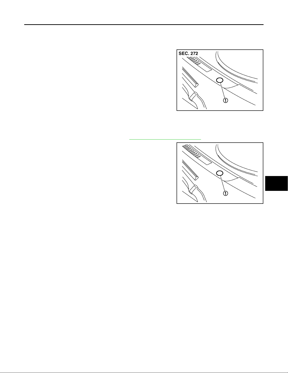
1. Sunload sensor
JSIIA0218ZZ
Removal and Installation INFOID:0000000000959797
REMOVAL
1. Remove front defroster grille (left). Refer to IP-12, "Removal and Installation".
2. Disconnect sunload sensor connector , and then remove sunload
sensor (1).
A
B
C
D
E
F
G
H
INSTALLATION
Installation is basically the reverse order of removal.
JSIIA0050ZZ
VTL
J
K
L
M
N
O
P
VTL-27
Page 28
INTAKE SENSOR
Revision: October 2006
2007 G35 Sedan
< ON-VEHICLE REPAIR >
INTAKE SENSOR
Exploded View INFOID:0000000000959798
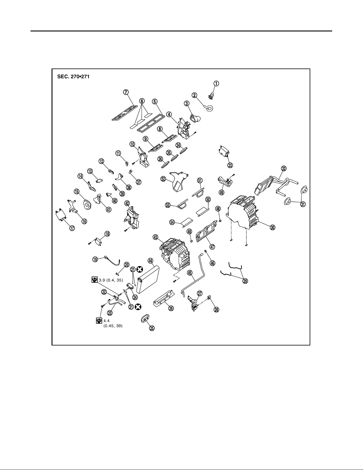
1. Aspirator 2. Aspirator hose 3. Front heater duct
4. Foot duct (left) 5. Defroster seal 6. Packing
7. Ventilator seal 8. Ventilator door (left) 9. Ventilator door (right)
10. Foot duct (right) 11. Defroster door lever 12. Foot door lever
13. Ventilator door lever 14. Ventilator door link 15. Main link
16. Mode door motor bracket 17. Mode door motor 18. Air mix door motor (passenger side)
19. Intake sensor 20. Intake sensor bracket 21. O-ring
22. Low-pressure pipe 1 23. High-pressure pipe 2 24. Expansion valve
25. Cooler pipe grommet 26. Insulator 27. Evaporator cover adapter
28. Heater pipe bracket 29. Case packing 30. Heater & cooling unit case (left)
31. Heater pipe grommet 32. Heater core 33.
34. Foot door (left) 35. Rear ventilator door 36. Foot door (right)
VTL-28
JSIIA0016GB
Air mix door motor (driver side)
*
Page 29
INTAKE SENSOR
Revision: October 2006
2007 G35 Sedan
< ON-VEHICLE REPAIR >
37. Max. cool door lever 38. Foot door link 39. Defroster door link
40. Max. cool door link 41. Main link sub 42. Evaporator cover
43. Heater & cooling unit case (right) 44. Evaporator 45. Drain hose
46. Clamp 47. Air mix door (Slide door) 48. Air mix door adapter
49. Heater pipe cover 50. Max. cool door (left) 51. Defroster door (left)
52. Center case 53. Defroster door (right) 54. Max. cool door (right)
*
With left and right ventilation temperature separately system.
Refer to GI-4, "
Components" for symbols in the figure.
Removal and Installation INFOID:0000000000959799
REMOVAL
1. Remove low-pressure pipe 1 and high-pressure pipe 2. Refer to HA-51, "Removal and Installation".
CAUTION:
Cap or wrap the joint of low-pressure pipe 1, 2 and high-pressure pipe 1, 2 with suitable material
such as vinyl tape to avoid the entry of air.
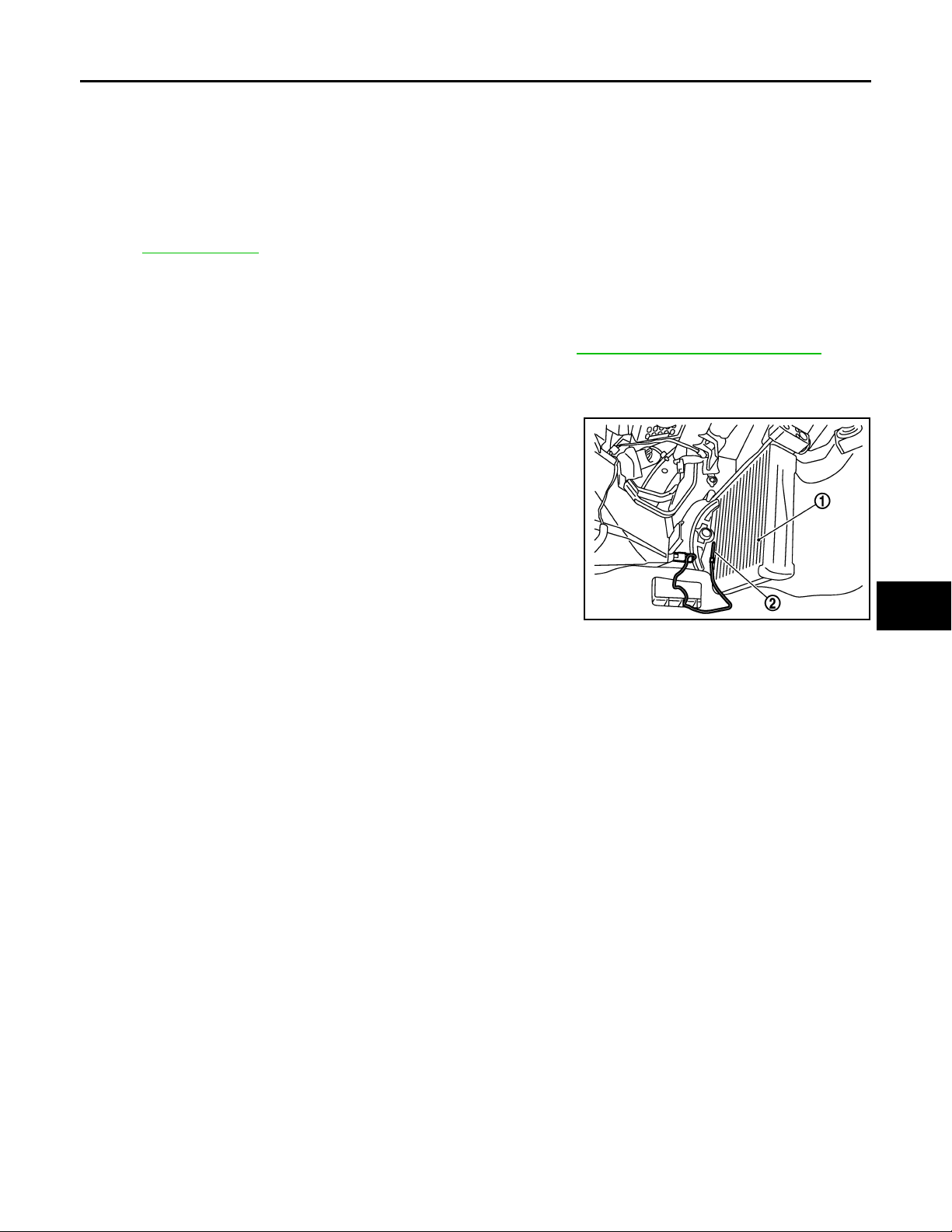
2. Slide evaporator (1) to passenger side, and then remove intake
sensor (2).
A
B
C
D
E
F
G
JSIIA0052ZZ
INSTALLATION
Installation is basically the reverse order of removal.
CAUTION:
• Replace O-rings of low-pressure pipe 1, 2 and high-pressure pipe 1, 2 with new ones, and then apply
compressor oil to it when installing it.
• Mark the mounting position of intake sensor bracket prior to removal so that the reinstalled sensor
can be located in the same position.
• Female-side piping connection is thin and easy to deform. Slowly insert the male-side piping
straight in axial direction.
• Insert piping securely until a click is heard.
• After piping connection is completed, pull male-side piping by hand to make sure that connection
does not come loose.
• When recharging refrigerant, check for leaks.
H
VTL
J
K
L
M
N
O
P
VTL-29
Page 30
BLOWER UNIT
Revision: October 2006
2007 G35 Sedan
< ON-VEHICLE REPAIR >
BLOWER UNIT
Exploded View INFOID:0000000000959800
JSIIA0009ZZ
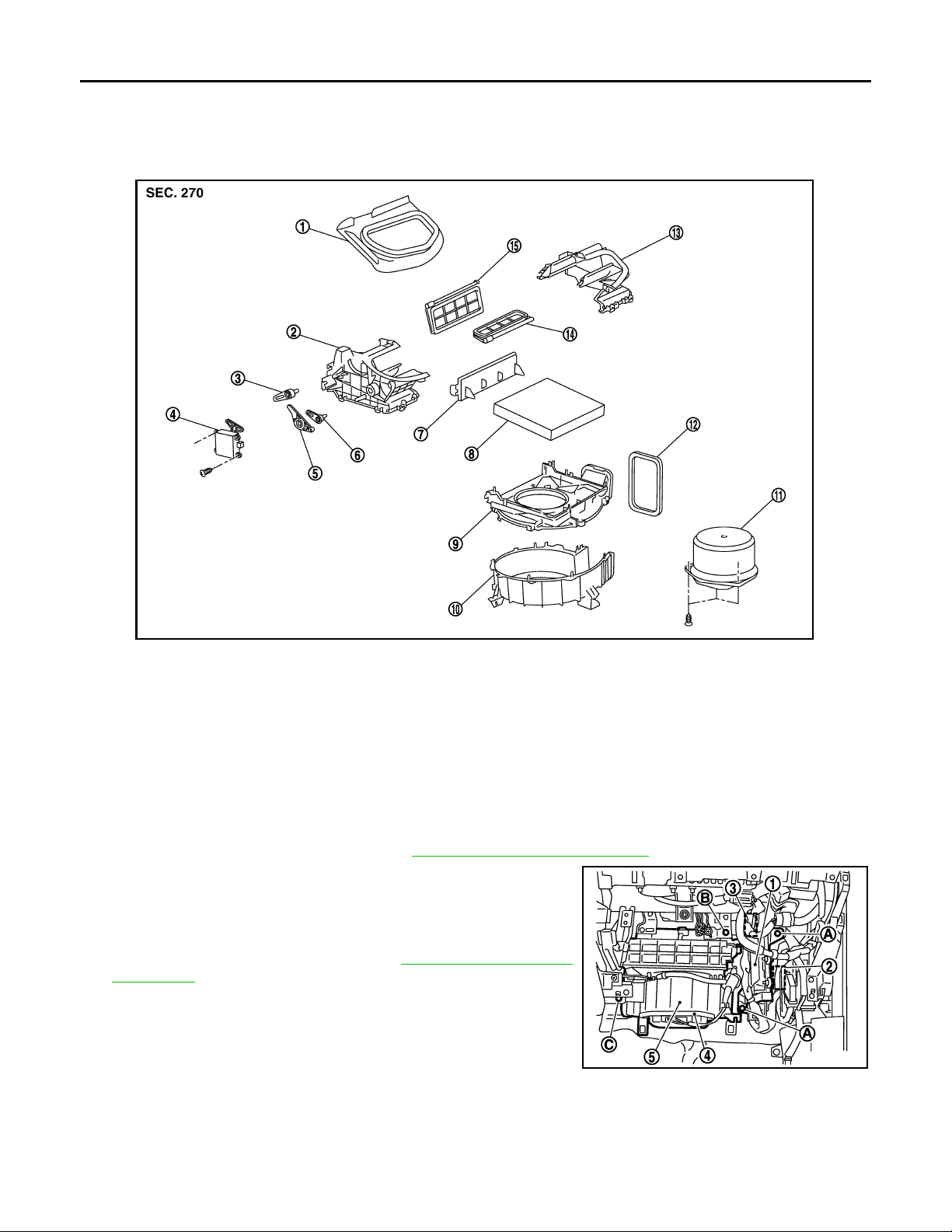
1. Adapter 2. Intake box (right) 3. Intake door lever 2
4. Intake door motor 5. Intake door link 6. Intake door lever 1
7. Filter cover 8. In-cabin microfilter 9. Intake upper case
10. Intake lower case 11. Blower motor assembly 12. Seal
13. Intake box (left) 14. Intake door 1 15. Intake door 2
Removal and Installation INFOID:0000000000959801
REMOVAL
1. Remove instrument lower panel. Refer to IP-12, "Removal and Installation".
2. Disconnect ECM (1) connectors.
3. Disconnect AWD control unit (2) connector (AWD).
4. Remove mounting nuts (A), and then remove ECM with bracket
attached.
5. Remove power steering C/U. Refer to STC-24, "
Installation".
6. Disconnect intake door motor (3) connector and blower fan
motor (4) connector.
7. Remove mounting bolt (B) and screw (C), from blower unit (5).
8. Remove blower unit.
CAUTION:
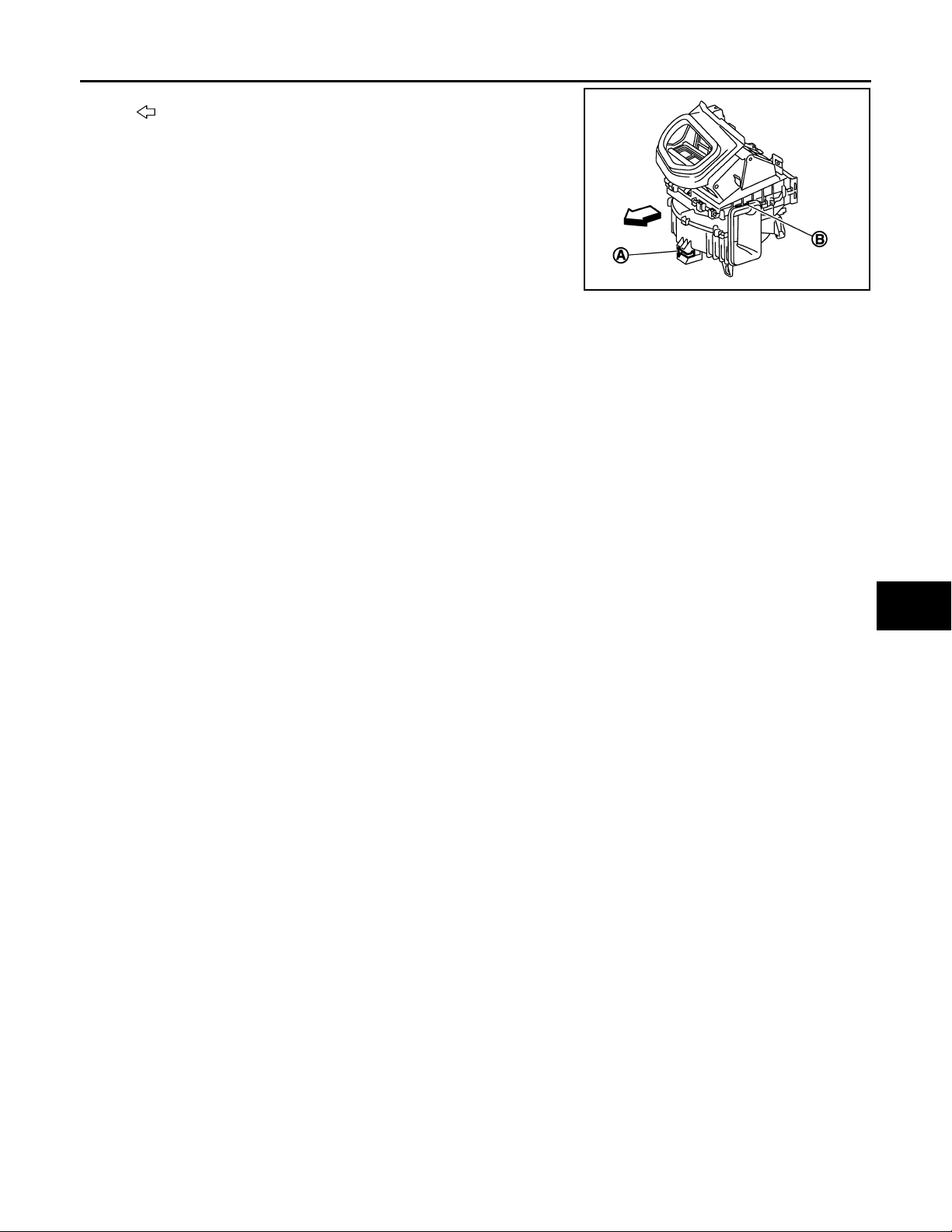
Move blower unit rightward, and remove locating pin (1 part) and joint. Then remove blower unit
downward.
Removal and
JSIIA0035ZZ
INSTALLATION
Installation is basically the reverse order of removal.
VTL-30
Page 31
< ON-VEHICLE REPAIR >
Revision: October 2006
2007 G35 Sedan
BLOWER UNIT
Vehicle front
:
CAUTION:
Make sure locating pin (A) and joint (B) are securely inserted.
A
B
C
JSIIA0008ZZ
D
E
F
G
H
VTL
J
K
L
M
N
O
P
VTL-31
Page 32
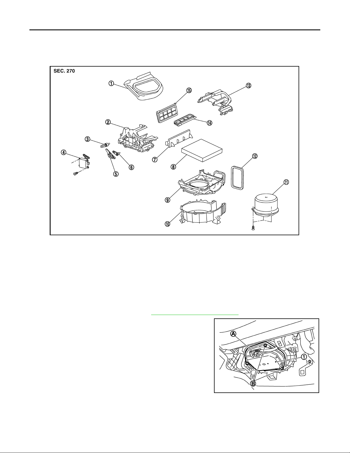
BLOWER MOTOR
Revision: October 2006
2007 G35 Sedan
< ON-VEHICLE REPAIR >
BLOWER MOTOR
Exploded View INFOID:0000000000959802
JSIIA0009ZZ
1. Adapter 2. Intake box (right) 3. Intake door lever 2
4. Intake door motor 5. Intake door link 6. Intake door lever 1
7. Filter cover 8. In-cabin microfilter 9. Intake upper case
10. Intake lower case 11. Blower motor assembly 12. Seal
13. Intake box (left) 14. Intake door 1 15. Intake door 2
Removal and Installation INFOID:0000000000959803
REMOVAL
1. Remove instrument lower cover. Refer to IP-12, "Removal and Installation".
2. Disconnect blower motor connector (A).
3. Remove mounting screws (B), and then remove blower motor
assembly (1).
JSIIA0033ZZ
INSTALLATION
Installation is basically the reverse order of removal.
VTL-32
Page 33
< ON-VEHICLE REPAIR >
Revision: October 2006
2007 G35 Sedan
INTAKE DOOR MOTOR
INTAKE DOOR MOTOR
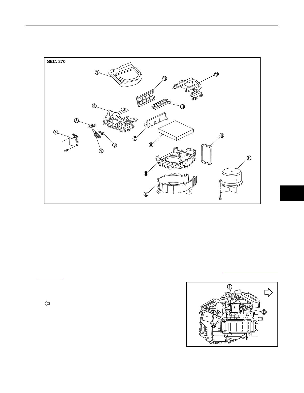
Exploded View INFOID:0000000000959804
A
B
C
D
E
F
G
H
JSIIA0009ZZ
1. Adapter 2. Intake box (right) 3. Intake door lever 2
4. Intake door motor 5. Intake door link 6. Intake door lever 1
7. Filter cover 8. In-cabin microfilter 9. Intake upper case
10. Intake lower case 11. Blower motor assembly 12. Seal
13. Intake box (left) 14. Intake door 1 15. Intake door 2
Removal and Installation INFOID:0000000000959805
REMOVAL
1. Remove ECM and power steering control unit with bracket attached. Refer to VTL-30, "Removal and
Installation".
2. Remove mounting screws (A), and then remove intake door
motor (1) from blower unit.
Vehicle front
:
3. Disconnect intake door motor connector (B).
VTL
J
K
L
M
N
O
P
INSTALLATION
Installation is basically the reverse order of removal.
JSIIA0108ZZ
VTL-33
Page 34
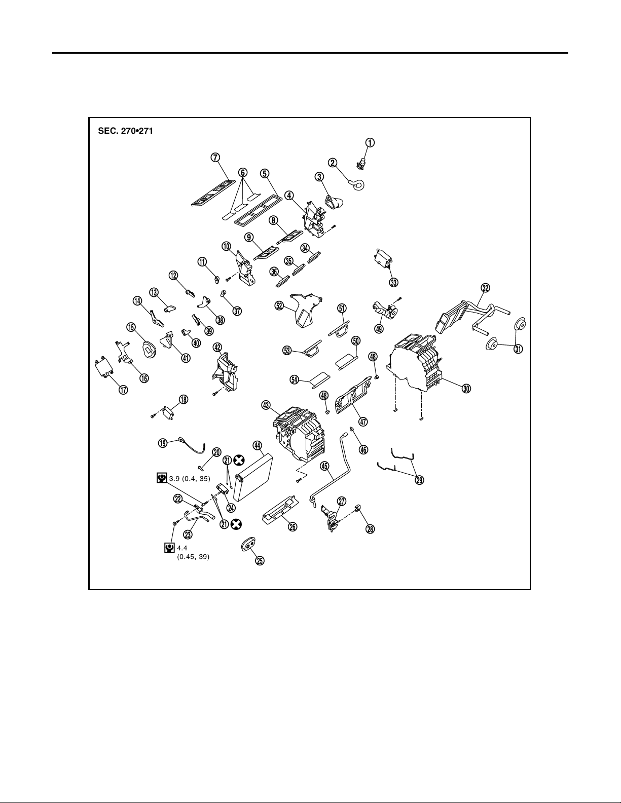
HEATER & COOLING UNIT ASSEMBLY
Revision: October 2006
2007 G35 Sedan
< ON-VEHICLE REPAIR >
HEATER & COOLING UNIT ASSEMBLY
Exploded View INFOID:0000000000959806
1. Aspirator 2. Aspirator hose 3. Front heater duct
4. Foot duct (left) 5. Defroster seal 6. Packing
7. Ventilator seal 8. Ventilator door (left) 9. Ventilator door (right)
10. Foot duct (right) 11. Defroster door lever 12. Foot door lever
13. Ventilator door lever 14. Ventilator door link 15. Main link
16. Mode door motor bracket 17. Mode door motor 18. Air mix door motor (passenger side)
19. Intake sensor 20. Intake sensor bracket 21. O-ring
22. Low-pressure pipe 1 23. High-pressure pipe 2 24. Expansion valve
25. Cooler pipe grommet 26. Insulator 27. Evaporator cover adapter
28. Heater pipe bracket 29. Case packing 30. Heater & cooling unit case (left)
31. Heater pipe grommet 32. Heater core 33.
34. Foot door (left) 35. Rear ventilator door 36. Foot door (right)
VTL-34
JSIIA0016GB
Air mix door motor (driver side)
*
Page 35
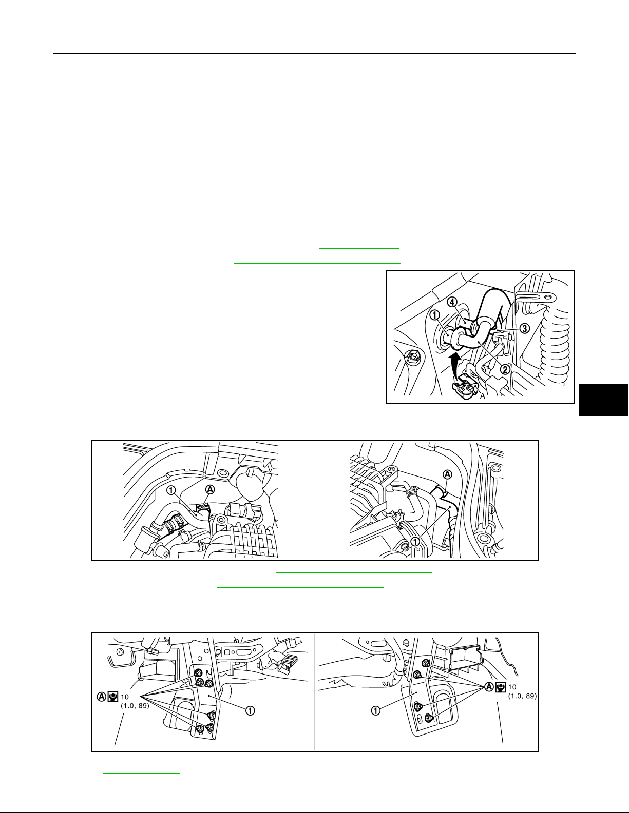
HEATER & COOLING UNIT ASSEMBLY
Revision: October 2006
2007 G35 Sedan
< ON-VEHICLE REPAIR >
37. Max. cool door lever 38. Foot door link 39. Defroster door link
40. Max. cool door link 41. Main link sub 42. Evaporator cover
43. Heater & cooling unit case (right) 44. Evaporator 45. Drain hose
46. Clamp 47. Air mix door (Slide door) 48. Air mix door adapter
49. Heater pipe cover 50. Max. cool door (left) 51. Defroster door (left)
52. Center case 53. Defroster door (right) 54. Max. cool door (right)
*
With left and right ventilation temperature separately system.
Refer to GI-4, "
Components" for symbols in the figure.
Removal and Installation INFOID:0000000000959807
REMOVAL
1. Use a refrigerant collecting equipment (for HFC-134a) to discharge the refrigerant.
2. Drain engine coolant from cooling system. Refer to CO-8, "
3. Remove cowl top cover. Refer to EXT-18, "
Removal and Installation".
4. Disconnect one-touch joint between low-pressure pipe 1 (1) and
low-pressure pipe 2 (2) with disconnector (SST: 9253089916)
(A).
CAUTION:
Cap or wrap the joint of low-pressure pipe 1 and low-pressure pipe 2 with suitable material such as vinyl tape to
avoid the entry of air.
5. Disconnect one-touch joint between high-pressure pipe 1 (3)
and high-pressure pipe 2 (4) with disconnector (SST:
9253089908).
CAUTION:
Cap or wrap the joint of high-pressure pipe 1 and high-pressure pipe 2 with suitable material such as vinyl tape to avoid the entry of air.
6. Remove clamp (A), and then disconnect heater hoses (1).
Draining".
JSIIA0037ZZ
A
B
C
D
E
F
G
H
VTL
J
7. Remove instrument panel & pad. Refer to IP-12, "
8. Remove blower unit. Refer to VTL-30, "
Removal and Installation".
Removal and Installation".
9. Remove clips of vehicle harness from steering member.
10. Remove mounting nuts (A), and then remove instrument stays (1).
Refer to GI-4, "
Components" for symbols in the figure.
K
L
JSIIA0042ZZ
M
N
O
P
JSIIA0136GB
VTL-35
Page 36
HEATER & COOLING UNIT ASSEMBLY
Revision: October 2006
2007 G35 Sedan
< ON-VEHICLE REPAIR >
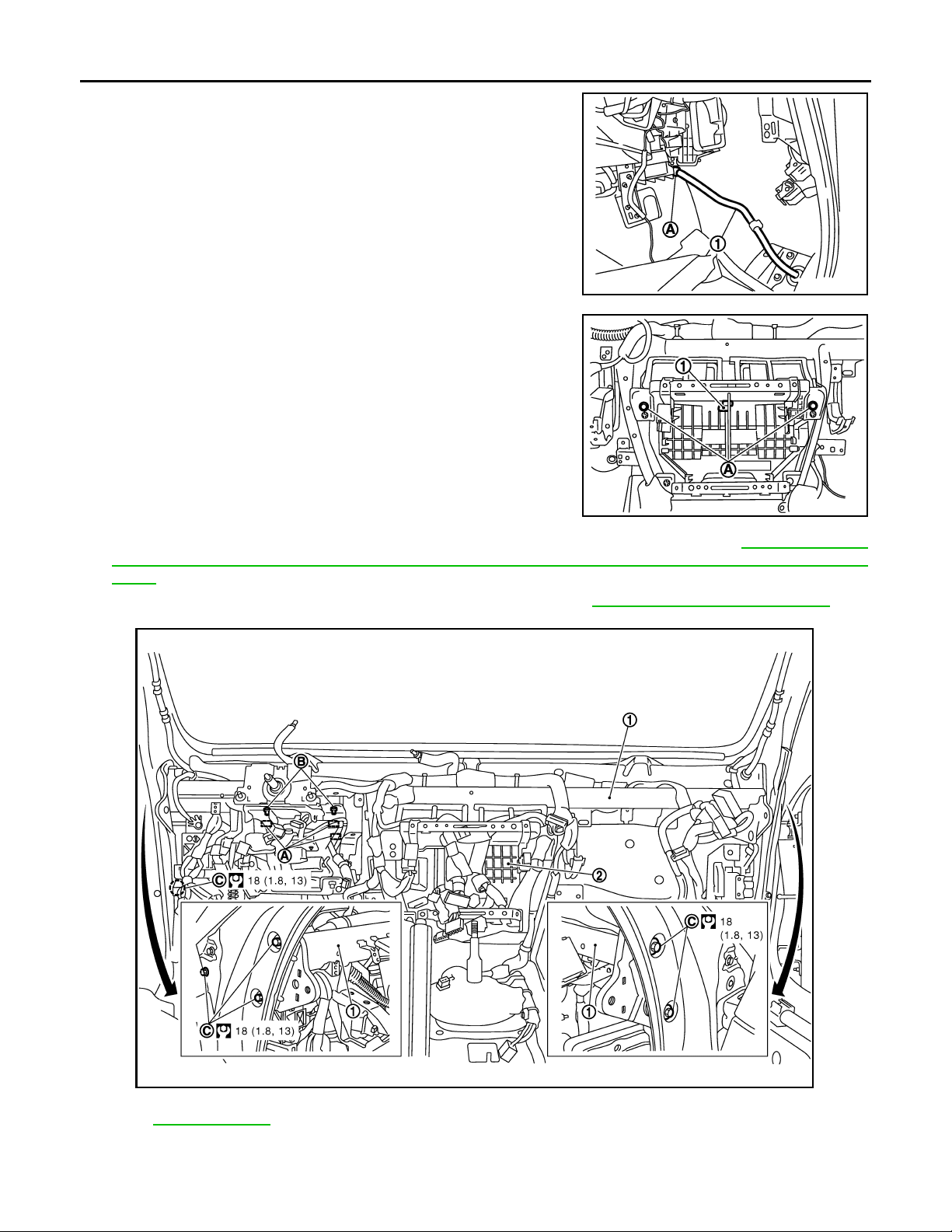
11. Remove clamp (A), and then remove drain hose (1).
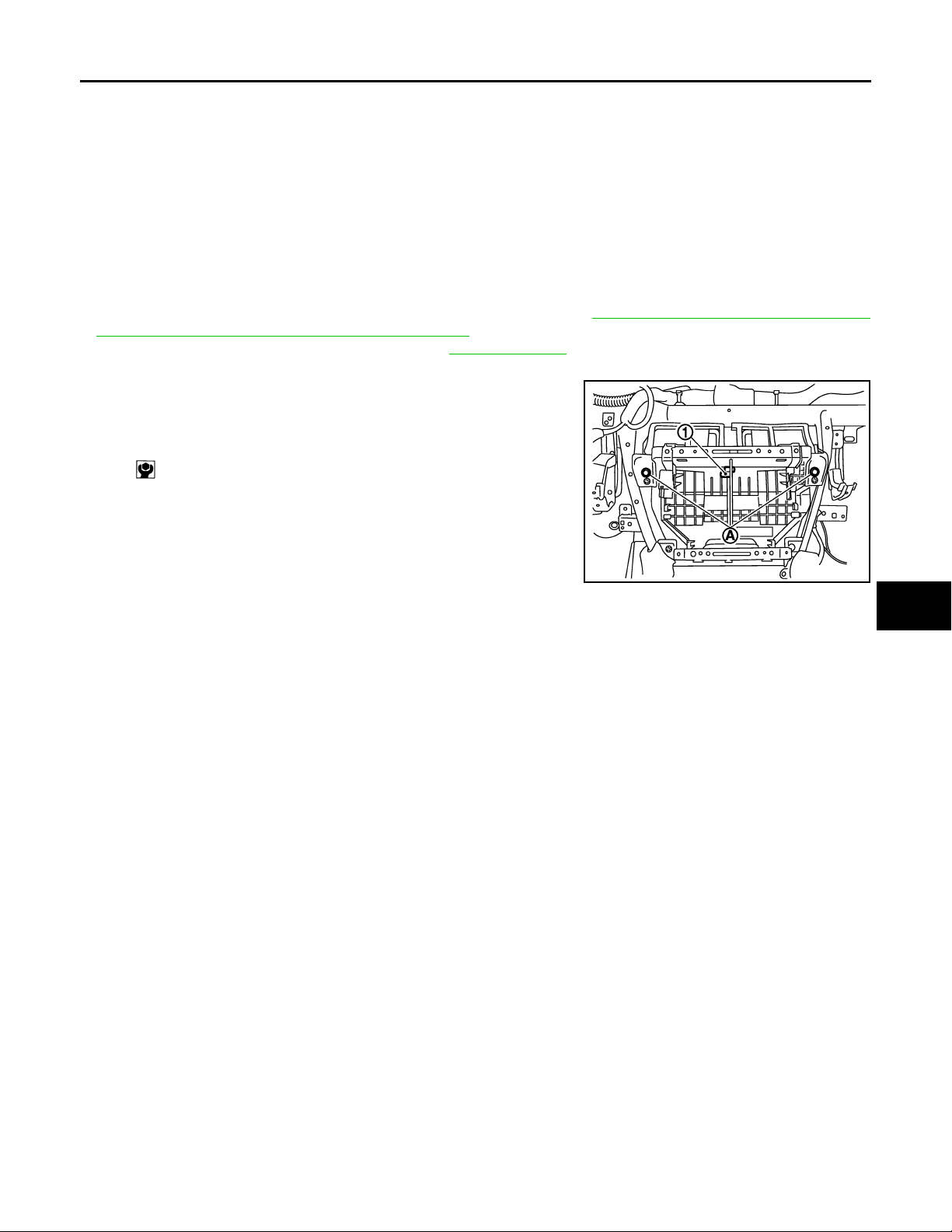
12. Remove mounting bolts (A) from heater & cooling unit assembly
(1).
JSIIA0038ZZ
13. Remove front defroster nozzle, side defroster nozzles and ventilator duct. Refer to VTL-46, "
DEFROSTER NOZZLE, SIDE DEFROSTER NOZZLES AND VENTILATOR DUCT : Removal and Installation".
14. Remove steering column mounting bolts (A) and nuts (B). Refer to IP-12, "
Removal and Installation".
JSIIA0039ZZ
FRONT
Refer to GI-4, "Components" for symbols in the figure.
15. Remove steering member mounting bolts (C).
16. Remove steering member (1), and then remove heater & cooling unit (2).
JSIIA0083GB
VTL-36
Page 37
HEATER & COOLING UNIT ASSEMBLY
Revision: October 2006
2007 G35 Sedan
< ON-VEHICLE REPAIR >
INSTALLATION
Installation is basically the reverse order of removal.
CAUTION:
• Replace O-rings of low-pressure pipe 1, 2 and high-pressure pipe 1, 2 with new ones, and then apply
compressor oil to it when installing it.
• Female-side piping connection is thin and easy to deform. Slowly insert the male-side piping
straight in axial direction.
• Insert piping securely until a clicks is heard.
• After piping connection is completed, pull male-side piping by hand to make sure that connection
does not come loose.
• When recharging refrigerant, check for leaks.
NOTE:
• Perform 4WAS front actuator adjustment (WITH 4WAS). Refer to STC-27, "
NEUTRAL POSITION ADJUSTMENT : Description".
• When filling radiator with engine coolant, refer to CO-9, "
Refilling".
• Recharge the refrigerant.
Heater & cooling unit (1)
assembly mounting bolt
(A)
: 6.9 N·m (0.7 kg·m, 61 inlb)
4WAS FRONT ACTUATOR
A
B
C
D
E
F
G
JSIIA0039ZZ
H
VTL
J
K
L
M
N
O
P
VTL-37
Page 38
MODE DOOR MOTOR
Revision: October 2006
2007 G35 Sedan
< ON-VEHICLE REPAIR >
MODE DOOR MOTOR
Exploded View INFOID:0000000000959808
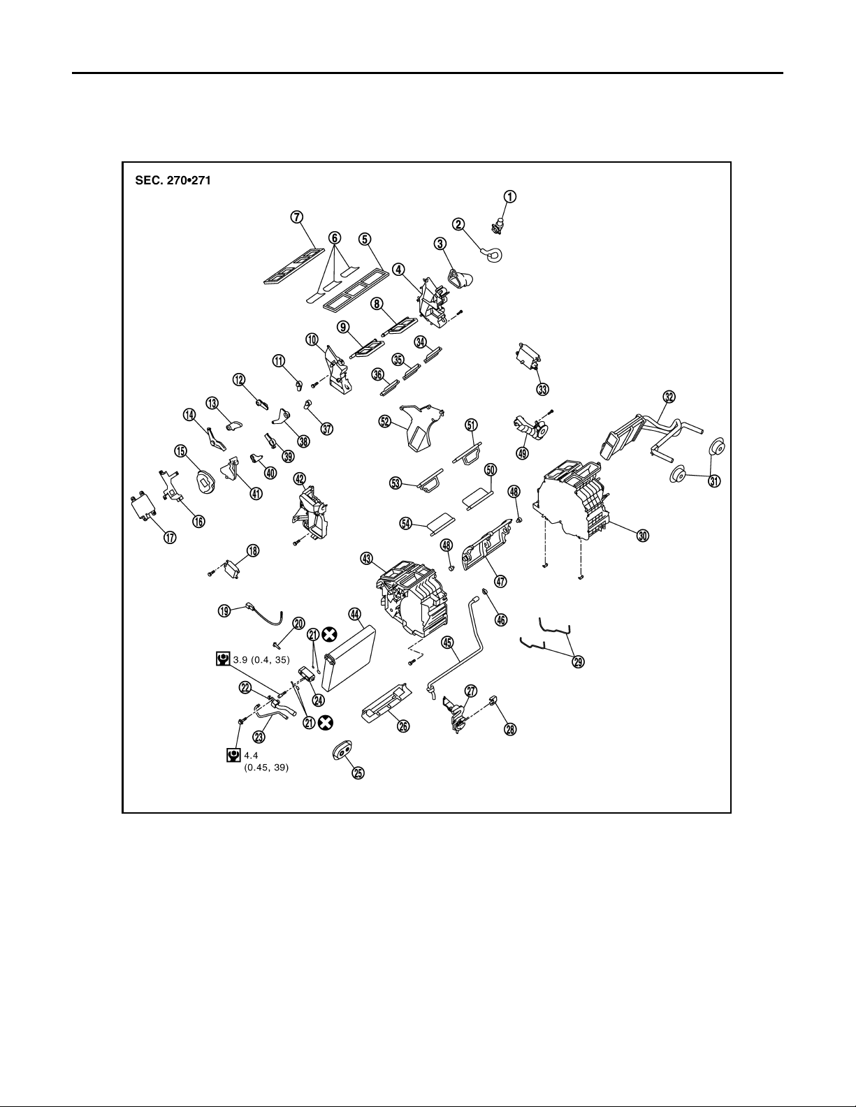
1. Aspirator 2. Aspirator hose 3. Front heater duct
4. Foot duct (left) 5. Defroster seal 6. Packing
7. Ventilator seal 8. Ventilator door (left) 9. Ventilator door (right)
10. Foot duct (right) 11. Defroster door lever 12. Foot door lever
13. Ventilator door lever 14. Ventilator door link 15. Main link
16. Mode door motor bracket 17. Mode door motor 18. Air mix door motor (passenger side)
19. Intake sensor 20. Intake sensor bracket 21. O-ring
22. Low-pressure pipe 1 23. High-pressure pipe 2 24. Expansion valve
25. Cooler pipe grommet 26. Insulator 27. Evaporator cover adapter
28. Heater pipe bracket 29. Case packing 30. Heater & cooling unit case (left)
31. Heater pipe grommet 32. Heater core 33.
34. Foot door (left) 35. Rear ventilator door 36. Foot door (right)
VTL-38
JSIIA0016GB
Air mix door motor (driver side)
*
Page 39
MODE DOOR MOTOR
Revision: October 2006
2007 G35 Sedan
< ON-VEHICLE REPAIR >
37. Max. cool door lever 38. Foot door link 39. Defroster door link
40. Max. cool door link 41. Main link sub 42. Evaporator cover
43. Heater & cooling unit case (right) 44. Evaporator 45. Drain hose
46. Clamp 47. Air mix door (Slide door) 48. Air mix door adapter
49. Heater pipe cover 50. Max. cool door (left) 51. Defroster door (left)
52. Center case 53. Defroster door (right) 54. Max. cool door (right)
*
With left and right ventilation temperature separately system.
Refer to GI-4, "
Components" for symbols in the figure.
Removal and Installation INFOID:0000000000959809
REMOVAL
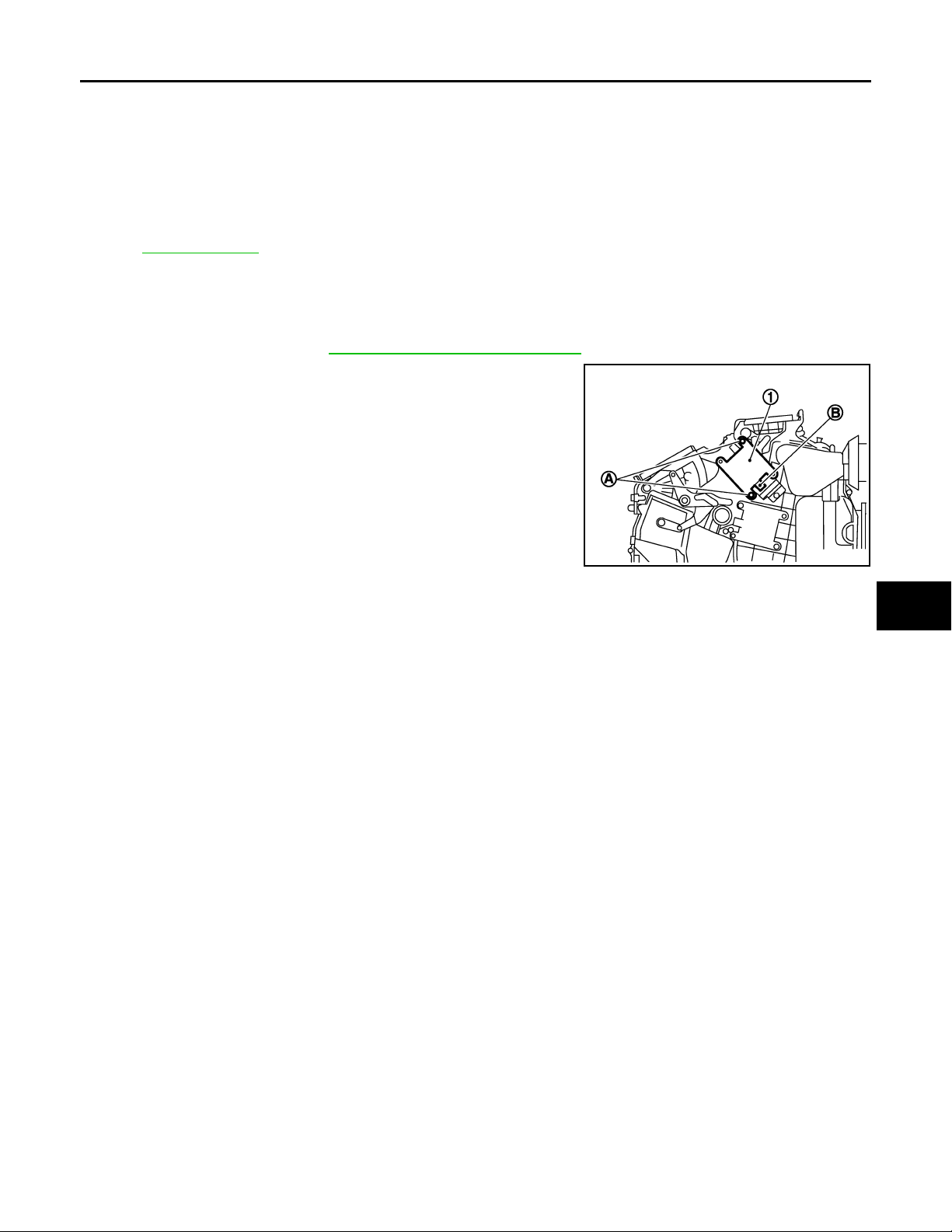
1. Remove blower unit. Refer to VTL-30, "Removal and Installation".
2. Remove mounting screws (A), and then remove mode door
motor (1).
3. Disconnect mode door motor connector (B).
A
B
C
D
E
F
G
INSTALLATION
installation is basically the reverse order of removal.
JSIIA0103ZZ
H
VTL
J
K
L
M
N
O
P
VTL-39
Page 40
AIR MIX DOOR MOTOR
Revision: October 2006
2007 G35 Sedan
< ON-VEHICLE REPAIR >
AIR MIX DOOR MOTOR
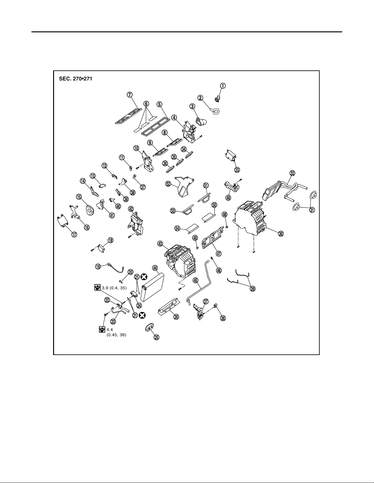
Exploded View INFOID:0000000000959810
1. Aspirator 2. Aspirator hose 3. Front heater duct
4. Foot duct (left) 5. Defroster seal 6. Packing
7. Ventilator seal 8. Ventilator door (left) 9. Ventilator door (right)
10. Foot duct (right) 11. Defroster door lever 12. Foot door lever
13. Ventilator door lever 14. Ventilator door link 15. Main link
16. Mode door motor bracket 17. Mode door motor 18. Air mix door motor (passenger side)
19. Intake sensor 20. Intake sensor bracket 21. O-ring
22. Low-pressure pipe 1 23. High-pressure pipe 2 24. Expansion valve
25. Cooler pipe grommet 26. Insulator 27. Evaporator cover adapter
28. Heater pipe bracket 29. Case packing 30. Heater & cooling unit case (left)
31. Heater pipe grommet 32. Heater core 33.
34. Foot door (left) 35. Rear ventilator door 36. Foot door (right)
VTL-40
JSIIA0016GB
Air mix door motor (driver side)
*
Page 41
AIR MIX DOOR MOTOR
Revision: October 2006
2007 G35 Sedan
< ON-VEHICLE REPAIR >
37. Max. cool door lever 38. Foot door link 39. Defroster door link
40. Max. cool door link 41. Main link sub 42. Evaporator cover
43. Heater & cooling unit case (right) 44. Evaporator 45. Drain hose
46. Clamp 47. Air mix door (Slide door) 48. Air mix door adapter
49. Heater pipe cover 50. Max. cool door (left) 51. Defroster door (left)
52. Center case 53. Defroster door (right) 54. Max. cool door (right)
*
With left and right ventilation temperature separately system.
Refer to GI-4, "
Components" for symbols in the figure.
Removal and Installation INFOID:0000000000959811
REMOVAL
A
B
C
D
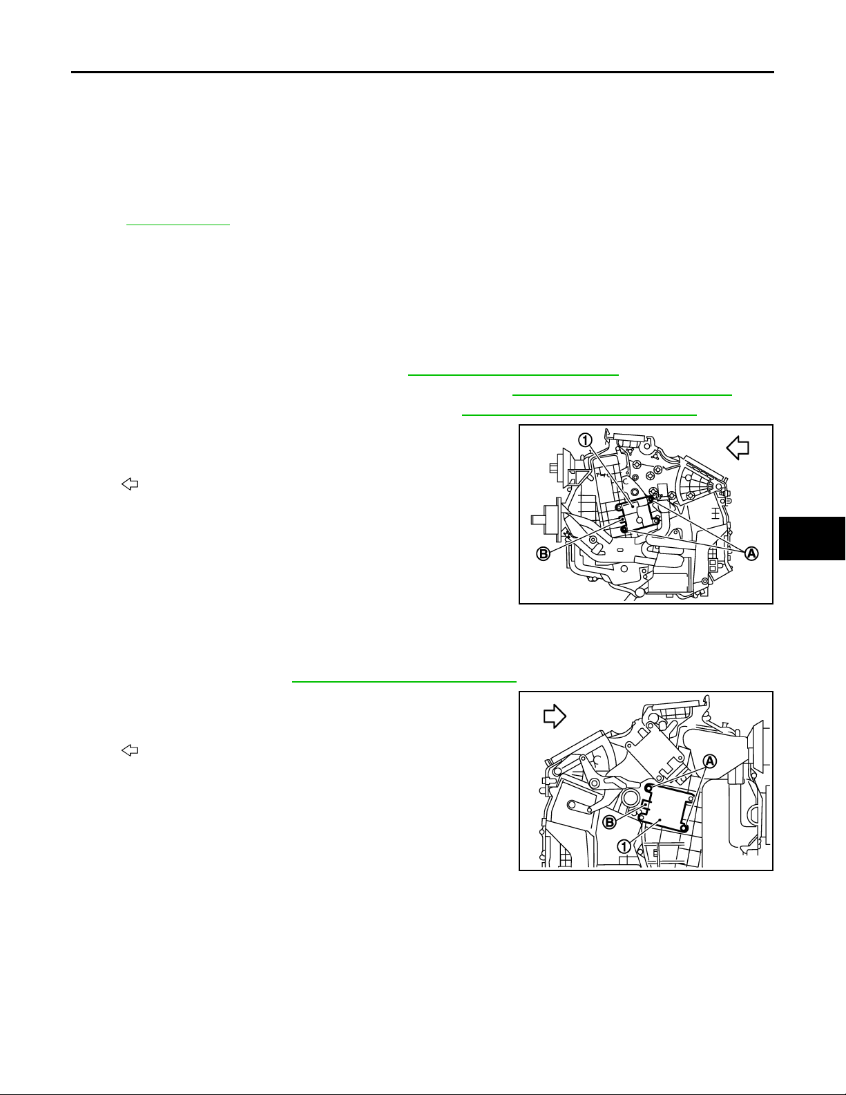
Driver Side (With left and right ventilation temperature separately system)
1. Set the temperature (driver side) at 18°C (60°F), and then disconnect the battery from the negative termi-
nal.
2. Remove instrument driver lower panel. Refer to IP-12, "
3. Remove accelerator pedal bracket and lever assembly. Refer to ACC-3, "
4. Remove automatic drive positioner control unit. Refer to ADP-218, "
Removal and Installation".
Removal and Installation".
Removal and Installation".
5. Remove mounting screws (A), and then remove air mix door
motor (1).
Vehicl e front
:
6. Disconnect air mix door motor connector (B).
JSIIA0104ZZ
Passenger Side
1. Set the temperature (passenger side) at 18°C (60°F), and then disconnect the battery from the negative
terminal.
2. Remove blower unit. Refer to VTL-30, "
Removal and Installation".
3. Remove mounting screws (A), and then remove air mix door
motor (1).
E
F
G
H
VTL
J
K
L
:
4. Disconnect air mix door motor connector (B).
INSTALLATION
Installation is basically the reverse order of removal.
Vehicl e front
VTL-41
JSIIA0105ZZ
M
N
O
P
Page 42
HEATER CORE
Revision: October 2006
2007 G35 Sedan
< ON-VEHICLE REPAIR >
HEATER CORE
Exploded View INFOID:0000000000959812
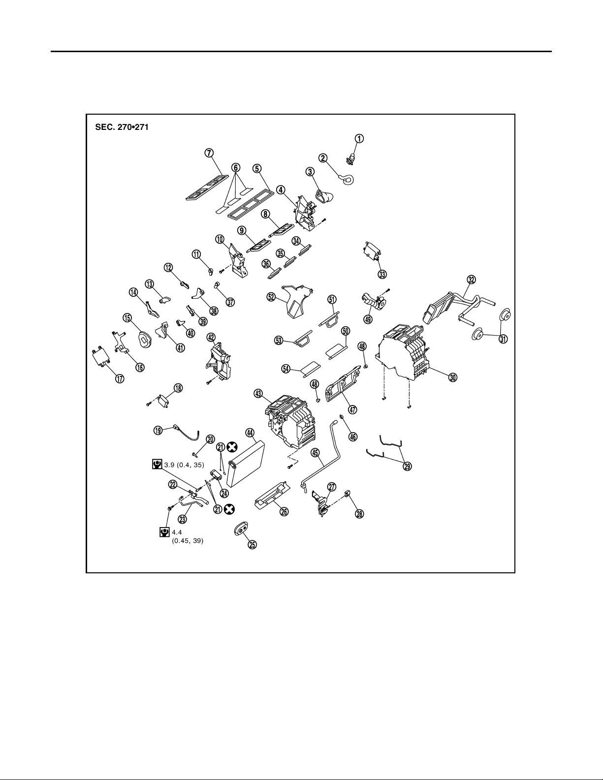
1. Aspirator 2. Aspirator hose 3. Front heater duct
4. Foot duct (left) 5. Defroster seal 6. Packing
7. Ventilator seal 8. Ventilator door (left) 9. Ventilator door (right)
10. Foot duct (right) 11. Defroster door lever 12. Foot door lever
13. Ventilator door lever 14. Ventilator door link 15. Main link
16. Mode door motor bracket 17. Mode door motor 18. Air mix door motor (passenger side)
19. Intake sensor 20. Intake sensor bracket 21. O-ring
22. Low-pressure pipe 1 23. High-pressure pipe 2 24. Expansion valve
25. Cooler pipe grommet 26. Insulator 27. Evaporator cover adapter
28. Heater pipe bracket 29. Case packing 30. Heater & cooling unit case (left)
31. Heater pipe grommet 32. Heater core 33.
34. Foot door (left) 35. Rear ventilator door 36. Foot door (right)
VTL-42
JSIIA0016GB
Air mix door motor (driver side)
*
Page 43
HEATER CORE
Revision: October 2006
2007 G35 Sedan
< ON-VEHICLE REPAIR >
37. Max. cool door lever 38. Foot door link 39. Defroster door link
40. Max. cool door link 41. Main link sub 42. Evaporator cover
43. Heater & cooling unit case (right) 44. Evaporator 45. Drain hose
46. Clamp 47. Air mix door (Slide door) 48. Air mix door adapter
49. Heater pipe cover 50. Max. cool door (left) 51. Defroster door (left)
52. Center case 53. Defroster door (right) 54. Max. cool door (right)
*
With left and right ventilation temperature separately system.
Refer to GI-4, "
Components" for symbols in the figure.
Removal and Installation INFOID:0000000000959813
REMOVAL
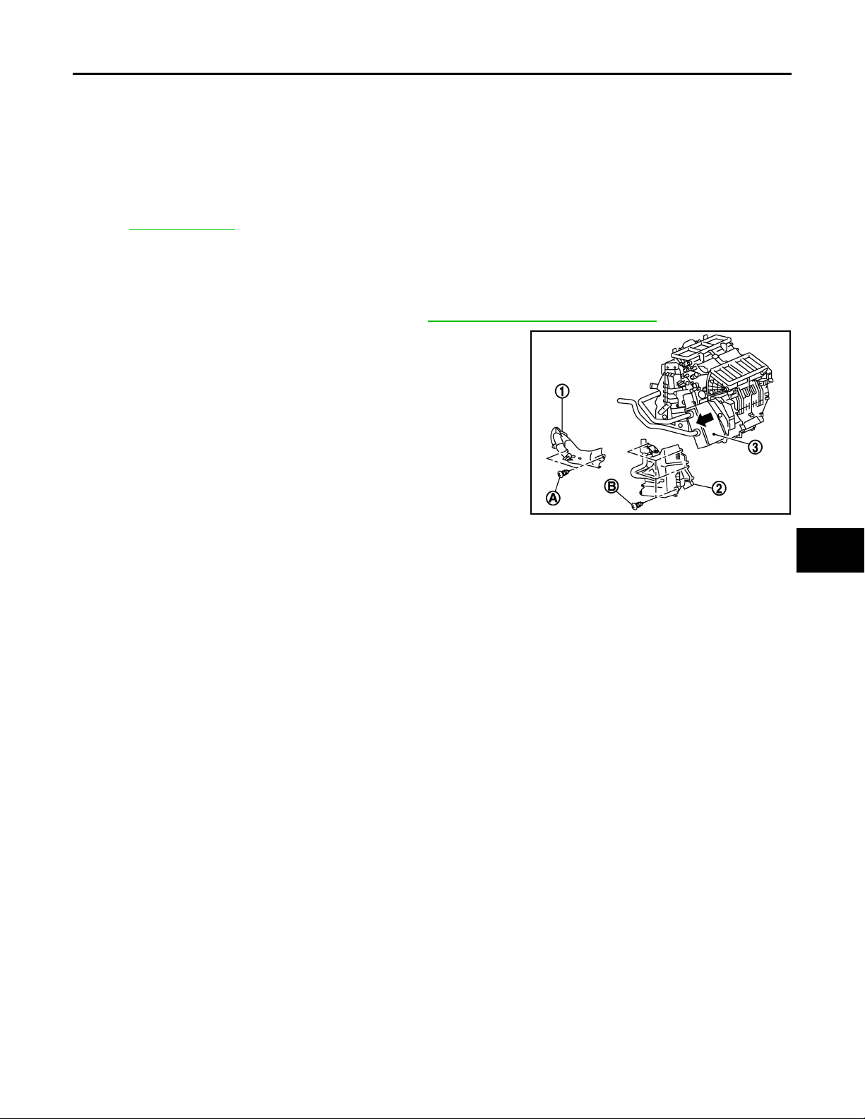
1. Remove heater & cooling unit assembly. Refer to VTL-35, "Removal and Installation".
2. Remove mounting screws (A), and then remove heater pipe
cover (1).
3. Remove mounting screws (B), and then remove foot duct (left)
(2).
4. Slide heater core (3) to leftward (shown in the figure).
A
B
C
D
E
F
G
INSTALLATION
Installation is basically the reverse order of removal.
JSIIA0017GB
H
VTL
J
K
L
M
N
O
P
VTL-43
Page 44
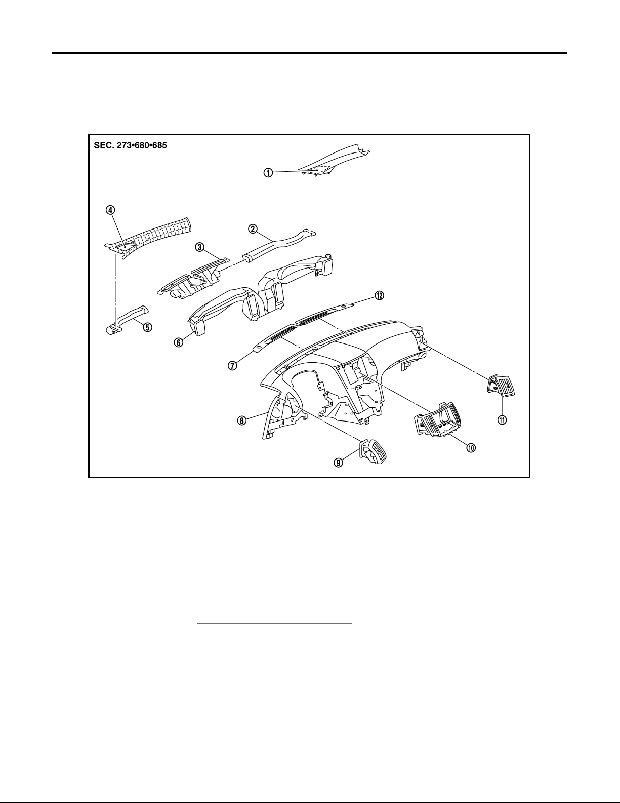
DUCTS AND GRILLES
Revision: October 2006
2007 G35 Sedan
< ON-VEHICLE REPAIR >
DUCTS AND GRILLES
CENTER VENTILATOR GRILLES
CENTER VENTILATOR GRILLES : Exploded View INFOID:0000000000959814
JSIIA0018ZZ
1. Side defroster duct (front pillar garnish) (right)
4. Side defroster duct (front pillar garnish) (left)
7. Front defroster grille (left) 8. Instrument panel & pad 9. Side ventilator grille (left)
10. Center ventilator grille (cluster lid D) 11. Side ventilator grille (right) 12. Front defroster grille (right)
2. Side defroster nozzle (right) 3. Defroster nozzle
5. Side defroster nozzle (left) 6. Ventilator duct
CENTER VENTILATOR GRILLES : Removal and Installation INFOID:0000000000959815
REMOVAL
Remove cluster lid D. Refer to IP-12, "Removal and Installation".
INSTALLATION
Installation is basically the reverse order of removal.
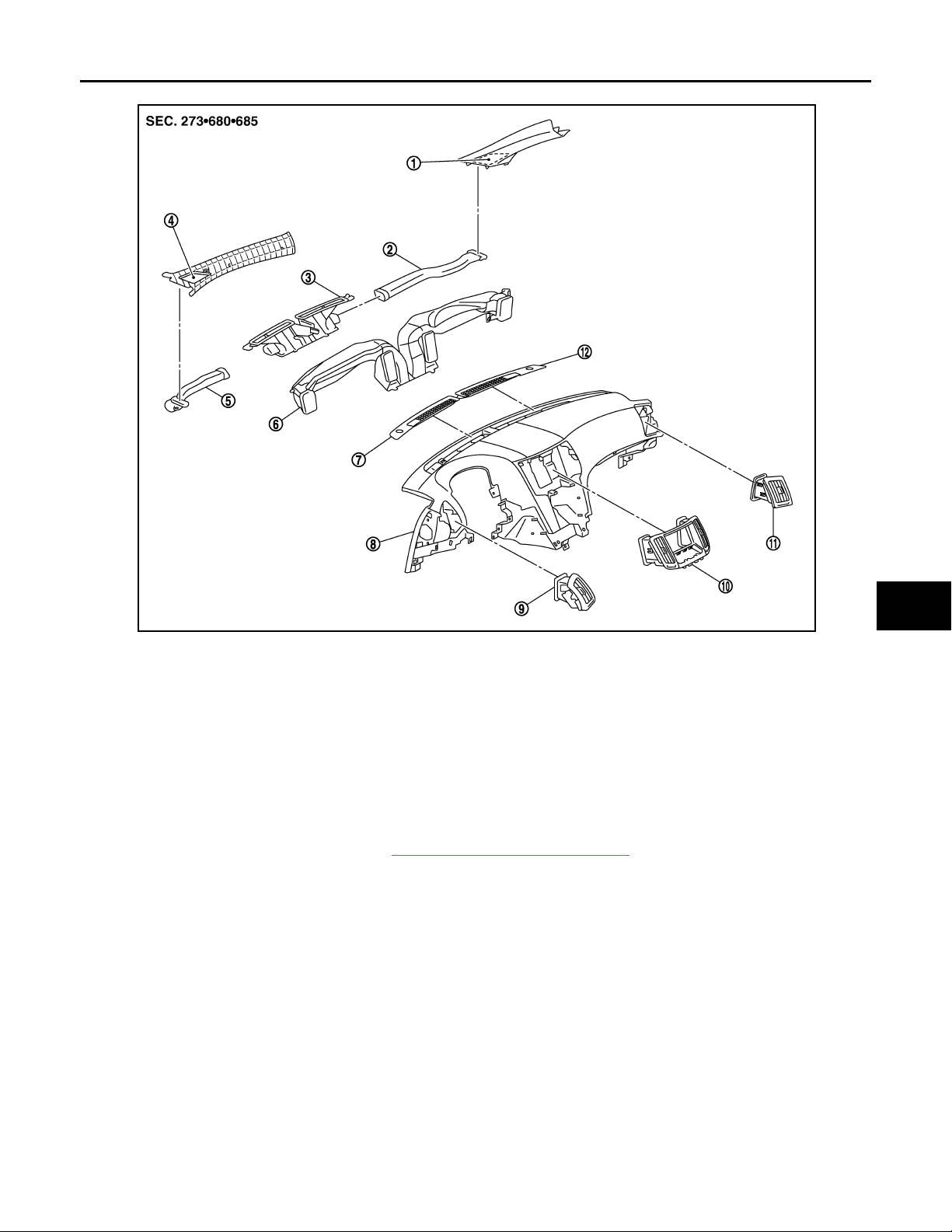
SIDE VENTILATOR GRILLES
SIDE VENTILATOR GRILLES : Exploded View INFOID:0000000000959816
VTL-44
Page 45
< ON-VEHICLE REPAIR >
Revision: October 2006
2007 G35 Sedan
DUCTS AND GRILLES
A
B
C
D
E
F
G
JSIIA0018ZZ
1. Side defroster duct (front pillar garnish) (right)
4. Side defroster duct (front pillar garnish) (left)
7. Front defroster grille (left) 8. Instrument panel & pad 9. Side ventilator grille (left)
10. Center ventilator grille (cluster lid D) 11. Side ventilator grille (right) 12. Front defroster grille (right)
2. Side defroster nozzle (right) 3. Defroster nozzle
5. Side defroster nozzle (left) 6. Ventilator duct
SIDE VENTILATOR GRILLES : Removal and Installation INFOID:0000000000959817
REMOVAL
Remove side ventilator assembly. Refer to IP-12, "Removal and Installation".
INSTALLATION
Installation is basically the reverse order of removal.
FRONT DEFROSTER NOZZLE, SIDE DEFROSTER NOZZLES AND VENTILATOR DUCT
FRONT DEFROSTER NOZZLE, SIDE DEFROSTER NOZZLES AND VENTILATOR
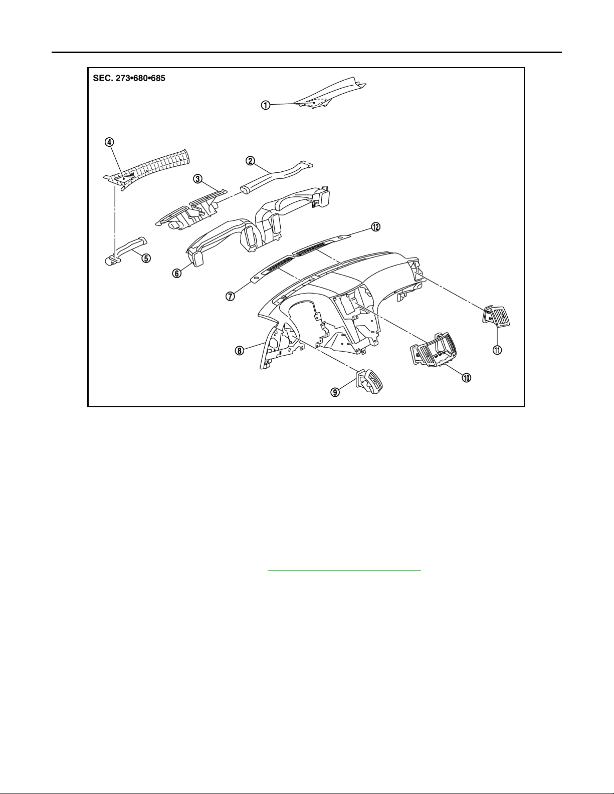
DUCT : Exploded View
INFOID:0000000000959818
H
VTL
J
K
L
M
N
O
P
VTL-45
Page 46
< ON-VEHICLE REPAIR >
Revision: October 2006
2007 G35 Sedan
DUCTS AND GRILLES
JSIIA0018ZZ
1. Side defroster duct (front pillar garnish) (right)
4. Side defroster duct (front pillar garnish) (left)
7. Front defroster grille (left) 8. Instrument panel & pad 9. Side ventilator grille (left)
10. Center ventilator grille (cluster lid D) 11. Side ventilator grille (right) 12. Front defroster grille (right)
2. Side defroster nozzle (right) 3. Defroster nozzle
5. Side defroster nozzle (left) 6. Ventilator duct
FRONT DEFROSTER NOZZLE, SIDE DEFROSTER NOZZLES AND VENTILATOR
DUCT : Removal and Installation
REMOVAL
1. Remove instrument panel & pad. Refer to IP-12, "Removal and Installation".
INFOID:0000000000959819
VTL-46
Page 47
< ON-VEHICLE REPAIR >
Revision: October 2006
2007 G35 Sedan
2. Remove mounting screw (A).
DUCTS AND GRILLES
A
B
C
D
E
JSIIA0043ZZ
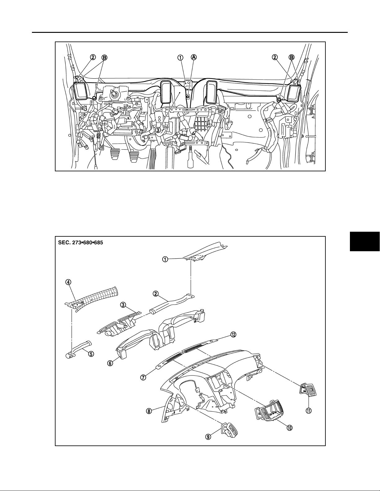
3. Remove clips (B), and then remove defroster nozzle (1), side defroster nozzle (2) and ventilator duct (3).
INSTALLATION
Installation is basically the reverse order of removal.
SIDE DEFROSTER DUCTS
SIDE DEFROSTER DUCTS : Exploded View INFOID:0000000000959820
F
G
H
VTL
J
K
L
M
N
O
P
JSIIA0018ZZ
VTL-47
Page 48
< ON-VEHICLE REPAIR >
Revision: October 2006
2007 G35 Sedan
DUCTS AND GRILLES
1. Side defroster duct (front pillar garnish) (right)
4. Side defroster duct (front pillar garnish) (left)
7. Front defroster grille (left) 8. Instrument panel & pad 9. Side ventilator grille (left)
10. Center ventilator grille (cluster lid D) 11. Side ventilator grille (right) 12. Front defroster grille (right)
SIDE DEFROSTER DUCTS : Removal and Installation
2. Side defroster nozzle (right) 3. Defroster nozzle
5. Side defroster nozzle (left) 6. Ventilator duct
INFOID:0000000000959821
REMOVAL
Remove front pillar garnishes Refer to INT-13, "Removal and Installation".
INSTALLATION
Installation is basically the reverse order of removal.
REAR VENTILATOR GRILLE
REAR VENTILATOR GRILLE : Exploded View INFOID:0000000000959822
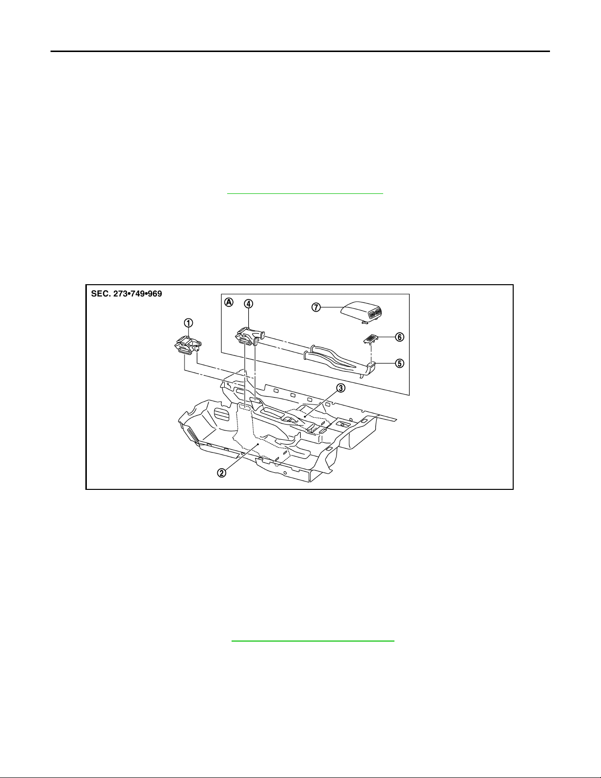
1. Rear floor duct 1 (without rear ventilator)
4. Rear floor duct 1& rear ventilator
duct 1
7. Rear ventilator grille (Console lid assembly)
A. With rear ventilator
REAR VENTILATOR GRILLE : Removal and Installation INFOID:0000000000959823
REMOVAL
Remove console lid assembly. Refer to IP-26, "Disassembly and Assembly".
INSTALLATION
Installation is basically the reverse order of removal.
REAR VENTILATOR DUCT 2
REAR VENTILATOR DUCT 2 : Exploded View INFOID:0000000000959824
JSIIA0019ZZ
2. Rear floor duct 2 (left) 3. Rear floor duct 2 (right)
5. Rear ventilator duct 2 6. Console mask
VTL-48
Page 49
< ON-VEHICLE REPAIR >
Revision: October 2006
2007 G35 Sedan
DUCTS AND GRILLES
A
B
C
D
E
JSIIA0019ZZ
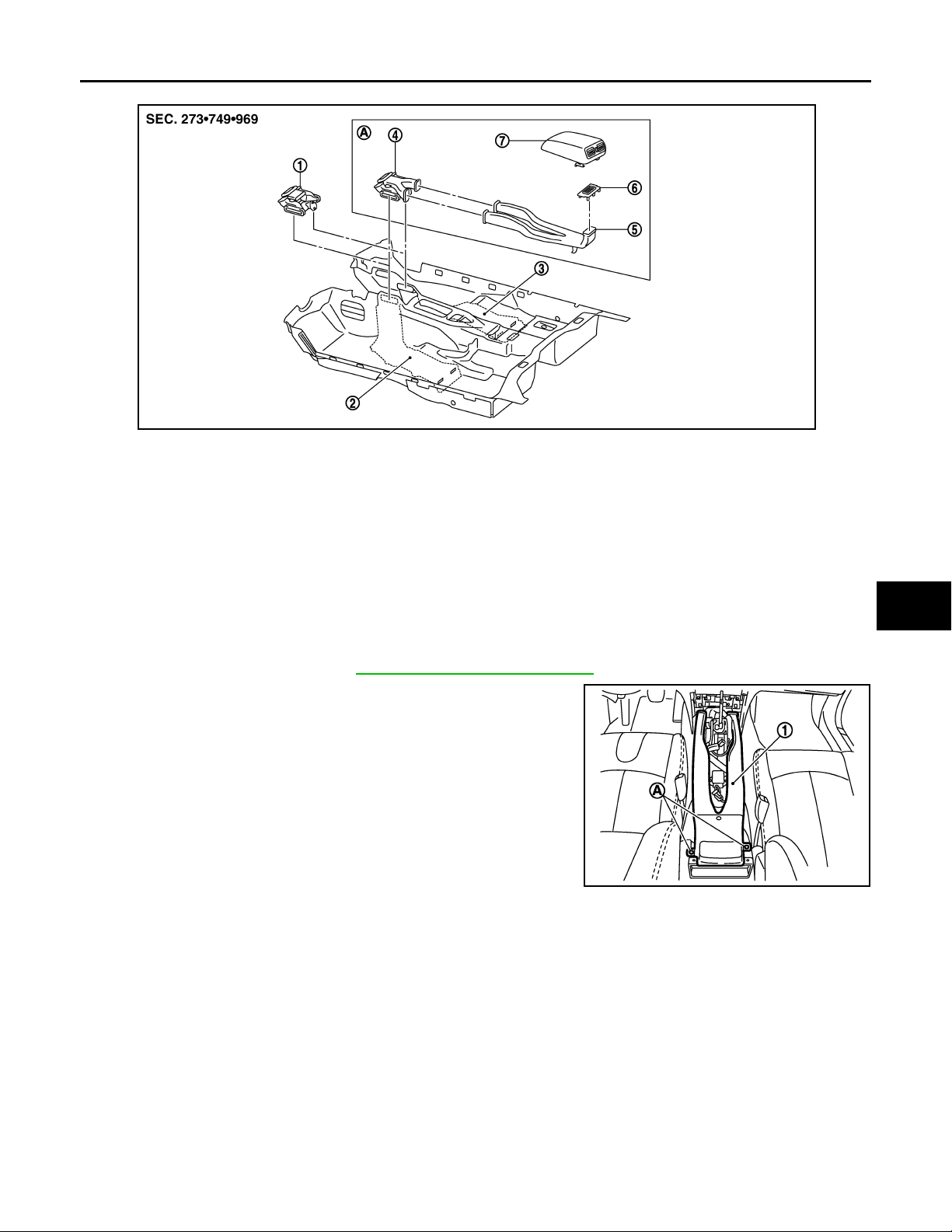
1. Rear floor duct 1 (without rear ventilator)
4. Rear floor duct 1& rear ventilator
duct 1
7. Rear ventilator grille (Console lid assembly)
A. With rear ventilator
2. Rear floor duct 2 (left) 3. Rear floor duct 2 (right)
5. Rear ventilator duct 2 6. Console mask
REAR VENTILATOR DUCT 2 : Removal and Installation INFOID:0000000000959825
REMOVAL
1. Remove center console. Refer to IP-12, "Removal and Installation".
2. Remove mounting screws (A), and then remove rear ventilator
duct 2 (1).
JSIIA0085ZZ
F
G
H
VTL
J
K
L
M
INSTALLATION
Installation is basically the reverse order of removal.
FOOT GRILLES
FOOT GRILLES : Exploded View INFOID:0000000000959826
N
O
P
VTL-49
Page 50
DUCTS AND GRILLES
Revision: October 2006
2007 G35 Sedan
< ON-VEHICLE REPAIR >
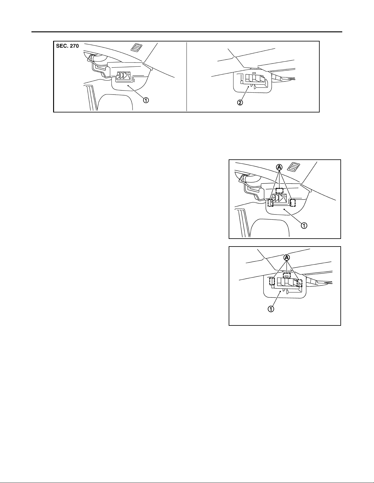
1. Foot grille (left) 2. Foot grille (right)
JSIIA0217ZZ
FOOT GRILLES : Removal and Installation
REMOVAL
1. Remove mounting clips (A), and then remove foot grille (left) (1).
2. Remove mounting clips (A), and then remove foot grille (right)
(1).
INFOID:0000000000959827
JSIIA0040ZZ
INSTALLATION
Installation is basically the reverse order of removal.
FOOT DUCTS
FOOT DUCTS : Exploded View INFOID:0000000000959828
JSIIA0041ZZ
VTL-50
Page 51
< ON-VEHICLE REPAIR >
Revision: October 2006
2007 G35 Sedan
DUCTS AND GRILLES
A
B
C
D
E
F
G
JSIIA0016GB
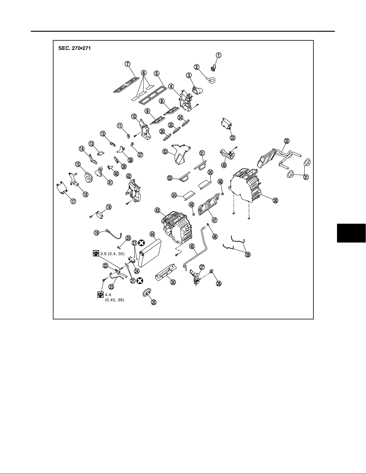
1. Aspirator 2. Aspirator hose 3. Front heater duct
4. Foot duct (left) 5. Defroster seal 6. Packing
7. Ventilator seal 8. Ventilator door (left) 9. Ventilator door (right)
10. Foot duct (right) 11. Defroster door lever 12. Foot door lever
13. Ventilator door lever 14. Ventilator door link 15. Main link
16. Mode door motor bracket 17. Mode door motor 18. Air mix door motor (passenger side)
19. Intake sensor 20. Intake sensor bracket 21. O-ring
22. Low-pressure pipe 1 23. High-pressure pipe 2 24. Expansion valve
25. Coo ler pip e gro mm et 26. Insulator 27. Evaporator co ve r adap te r
28. Heater pipe bracket 29. Case packing 30. Heater & cooling unit case (left)
31. Heater pipe grommet 32. Heater core 33.
34. Foot door (left) 35. Rear ventilator door 36. Foot door (right)
37. Max. cool door lever 38. Foot door link 39. Defroster door link
40. Max. cool door link 41. Main link sub 42. Evaporator cover
43. Heater & cooling unit case (right) 44. Evaporator 45. Drain hose
46. Clamp 47. Air mix door (Slide door) 48. Air mix door adapter
Air mix door motor (driver side)
*
H
VTL
J
K
L
M
N
O
P
VTL-51
Page 52
DUCTS AND GRILLES
Revision: October 2006
2007 G35 Sedan
< ON-VEHICLE REPAIR >
49. Heater pipe cover 50. Max. cool door (left) 51. Defroster door (left)
52. Center case 53. Defroster door (right) 54. Max. cool door (right)
*
With left and right ventilation temperature separately system.
Refer to GI-4, "
Components" for symbols in the figure.
FOOT DUCTS : Removal and Installation
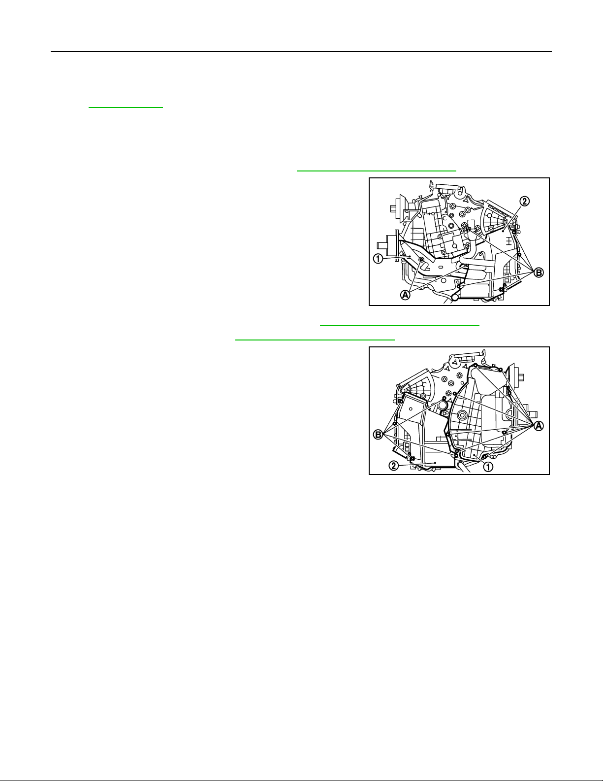
REMOVAL
1. Remove heater & cooling unit assembly. Refer to VTL-35, "Removal and Installation".
2. Remove mounting screws (A), and then remove heater pipe
cover (1).
3. Remove mounting screws (B), and then remove foot duct (left)
(2).
4. Remove air mix door motor (passenger side). Refer to VTL-41, "
5. Remove mode door motor. Refer to VTL-39, "
Removal and Installation".
6. Remove mounting screws (A), and then remove evaporator
cover (1).
7. Remove mounting screws (B), and then remove foot duct (right)
(2).
Removal and Installation".
INFOID:0000000000959829
JSIIA0106ZZ
JSIIA0107ZZ
INSTALLATION
Installation is basically the reverse order of removal.
REAR FLOOR DUCT 1 (WITHOUT REAR VENTILATOR)
REAR FLOOR DUCT 1 (WITHOUT REAR VENTILATOR) : Exploded ViewINFOID:0000000000959830
VTL-52
Page 53
< ON-VEHICLE REPAIR >
Revision: October 2006
2007 G35 Sedan
DUCTS AND GRILLES
A
B
C
D
E
JSIIA0019ZZ
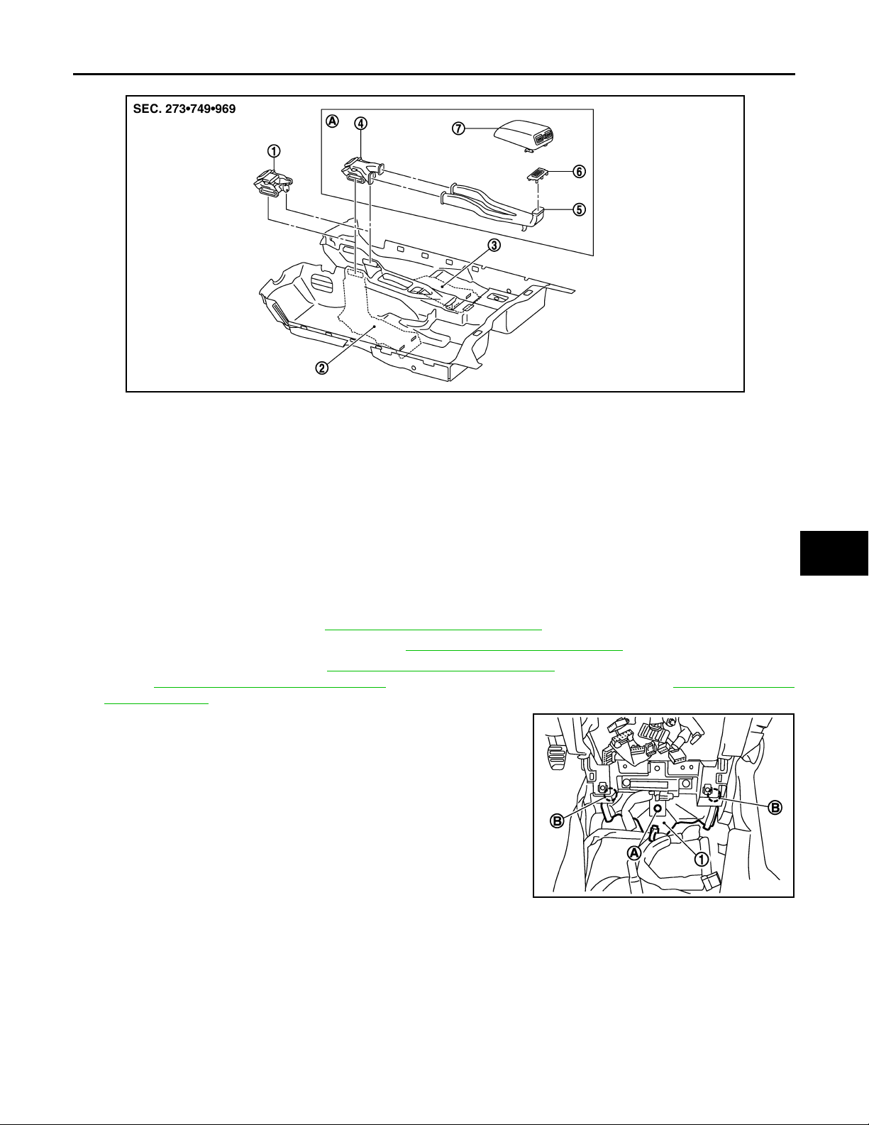
1. Rear floor duct 1 (without rear ventilator)
4. Rear floor duct 1& rear ventilator
duct 1
7. Rear ventilator grille (Console lid assembly)
A. With rear ventilator
2. Rear floor duct 2 (left) 3. Rear floor duct 2 (right)
5. Rear ventilator duct 2 6. Console mask
REAR FLOOR DUCT 1 (WITHOUT REAR VENTILATOR) : Removal and Installation
INFOID:0000000000959831
REMOVAL
1. Remove center console. Refer to IP-12, "Removal and Installation".
2. Remove Instrument side panel (RH). Refer to IP-12, "
3. Remove AV control unit. Refer to AV-111, "
TION), AV-292, "
Removal and Installation" (BOSE AUDIO WITHOUT NAVIGATION), AV-530, "Removal
Removal and Installation" (BASE AUDIO WITHOUT NAVIGA-
and Installation" (BOSE AUDIO WITH NAVIGATION).
4. Remove mounting clip (A).
5. Remove mounting clip (B), and then peel back floor carpet to a
point where rear floor duct 1 is visible.
6. Remove rear floor duct 1 to rightward.
Removal and Installation".
F
G
H
VTL
J
K
L
M
INSTALLATION
Installation is basically the reverse order of removal.
REAR FLOOR DUCT 1 & REAR VENTILATOR DUCT 1(WITH REAR VENTILATOR)
REAR FLOOR DUCT 1 & REAR VENTILATOR DUCT 1(WITH REAR VENTILATOR)
: Exploded View
VTL-53
JSIIA0074ZZ
INFOID:0000000000959832
N
O
P
Page 54
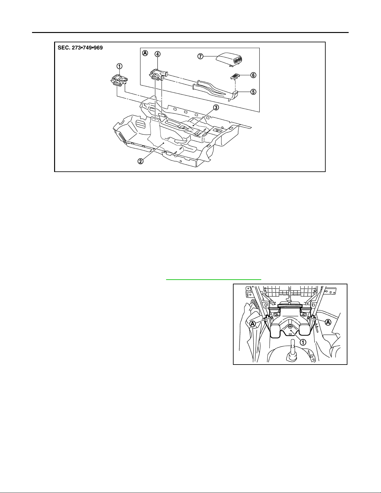
< ON-VEHICLE REPAIR >
Revision: October 2006
2007 G35 Sedan
DUCTS AND GRILLES
JSIIA0019ZZ
1. Rear floor duct 1 (without rear ventilator)
4. Rear floor duct 1& rear ventilator
duct 1
7. Rear ventilator grille (Console lid assembly)
A. With rear ventilator
2. Rear floor duct 2 (left) 3. Rear floor duct 2 (right)
5. Rear ventilator duct 2 6. Console mask
REAR FLOOR DUCT 1 & REAR VENTILATOR DUCT 1(WITH REAR VENTILATOR)
: Removal and Installation
REMOVAL
1. Remove instrument panel & pad. Refer to IP-12, "Removal and Installation".
2. Remove mounting clip (A), and then remove rear floor duct 1
(1).
INFOID:0000000000959833
JSIIA0084ZZ
INSTALLATION
Installation is basically the reverse order of removal.
VTL-54
 Loading...