

Page 1

Features
VNH2SP30-E
Automotive fully integrated H-bridge motor driver
Type R
VNH2SP30-E
■ 5V logic level compatible inputs
■ Undervoltage and overvoltage shut-down
■ Overvoltage clamp
■ Thermal shut down
■ Cross-conduction protection
■ Linear current limiter
■ Very low stand-by power consumption
■ PWM operation up to 20 kHz
■ Protection against loss of ground and loss of
V
CC
■ Current sense output proportional to motor
DS(on)
19mΩ max
(per leg)
I
V
out
30A 41V
ccmax
current
■ Package: ECOPACK
®
Description
The VNH2SP30-E is a full bridge motor driver
intended for a wide range of automotive
applications. The device incorporates a dual
monolithic high side driver and two low side
switches. The high side driver switch is designed
using STMicroelectronic’s well known and proven
proprietary VIPower
permits efficient integration on the same die of a
true Power MOSFET with an intelligent
signal/protection circuitry.
Table 1. Device summary
™
M0 technology which
MultiPowerSO-30™
The low side switches are vertical MOSFETs
manufactured using STMicroelectronic’s
proprietary EHD (‘STripFET™’) process. The
three die are assembled in the MultiPowerSO-30
package on electrically isolated leadframes. This
package, specifically designed for the harsh
automotive environment offers improved thermal
performance thanks to exposed die pads.
Moreover, its fully symmetrical mechanical design
allows superior manufacturability at board level.
The input signals IN
and INB can directly
A
interface to the microcontroller to select the motor
direction and the brake condition. The
DIAG
/ENA or DIAGB/ENB, when connected to an
A
external pull-up resistor, enable one leg of the
bridge. They also provide a feedback digital
diagnostic signal. The normal condition operation
is explained in Table 12: Truth table in normal
operating conditions on page 14. The motor
current can be monitored with the CS pin by
delivering a current proportional to its value. The
speed of the motor can be controlled in all
possible conditions by the PWM up to 20 kHz. In
all cases, a low level state on the PWM pin will
turn off both the LS
PWM rises to a high level, LS
and LSB switches. When
A
or LSB turn on
A
again depending on the input pin state.
Order codes
Package
Tube Tape and Reel
MultiPowerSO-30 VNH2SP30-E VNH2SP30TR-E
October 2008 Rev 8 1/33
www.st.com
1
Page 2

Contents VNH2SP30-E
Contents
1 Block diagram and pin description . . . . . . . . . . . . . . . . . . . . . . . . . . . . . 5
2 Electrical specifications . . . . . . . . . . . . . . . . . . . . . . . . . . . . . . . . . . . . . . 8
2.1 Absolute maximum ratings . . . . . . . . . . . . . . . . . . . . . . . . . . . . . . . . . . . . . 8
2.2 Electrical characteristics . . . . . . . . . . . . . . . . . . . . . . . . . . . . . . . . . . . . . . . 9
2.3 Electrical characteristics curves . . . . . . . . . . . . . . . . . . . . . . . . . . . . . . . . 16
3 Application information . . . . . . . . . . . . . . . . . . . . . . . . . . . . . . . . . . . . . 20
3.1 Reverse battery protection . . . . . . . . . . . . . . . . . . . . . . . . . . . . . . . . . . . . 21
4 Package and PCB thermal data . . . . . . . . . . . . . . . . . . . . . . . . . . . . . . . 25
4.1 PowerSSO-30 thermal data . . . . . . . . . . . . . . . . . . . . . . . . . . . . . . . . . . . 25
4.1.1 Thermal calculation in clockwise and anti-clockwise operation in steadystate mode 26
4.1.2 Thermal resistances definition (values according to the PCB heatsink
area) 26
4.1.3 Thermal calculation in transient mode . . . . . . . . . . . . . . . . . . . . . . . . . . 26
4.1.4 Single pulse thermal impedance definition
(values according to the PCB heatsink area) . . . . . . . . . . . . . . . . . . . . . 26
5 Package and packing information . . . . . . . . . . . . . . . . . . . . . . . . . . . . . 29
5.1 ECOPACK® packages . . . . . . . . . . . . . . . . . . . . . . . . . . . . . . . . . . . . . . . 29
5.2 MultiPowerSO-30 package mechanical data . . . . . . . . . . . . . . . . . . . . . . 29
5.3 Packing information . . . . . . . . . . . . . . . . . . . . . . . . . . . . . . . . . . . . . . . . . 31
6 Revision history . . . . . . . . . . . . . . . . . . . . . . . . . . . . . . . . . . . . . . . . . . . 32
2/33
Page 3

VNH2SP30-E List of tables
List of tables
Table 1. Device summary . . . . . . . . . . . . . . . . . . . . . . . . . . . . . . . . . . . . . . . . . . . . . . . . . . . . . . . . . . 1
Table 2. Block description. . . . . . . . . . . . . . . . . . . . . . . . . . . . . . . . . . . . . . . . . . . . . . . . . . . . . . . . . . 5
Table 3. Pin definitions and functions . . . . . . . . . . . . . . . . . . . . . . . . . . . . . . . . . . . . . . . . . . . . . . . . . 6
Table 4. Pin functions description . . . . . . . . . . . . . . . . . . . . . . . . . . . . . . . . . . . . . . . . . . . . . . . . . . . . 7
Table 5. Absolute maximum ratings . . . . . . . . . . . . . . . . . . . . . . . . . . . . . . . . . . . . . . . . . . . . . . . . . . 8
Table 6. Power section . . . . . . . . . . . . . . . . . . . . . . . . . . . . . . . . . . . . . . . . . . . . . . . . . . . . . . . . . . . . 9
Table 7. Logic inputs (INA, INB, ENA, ENB) . . . . . . . . . . . . . . . . . . . . . . . . . . . . . . . . . . . . . . . . . . . 9
Table 8. PWM . . . . . . . . . . . . . . . . . . . . . . . . . . . . . . . . . . . . . . . . . . . . . . . . . . . . . . . . . . . . . . . . . . 10
Table 9. Switching (V
Table 10. Protection and diagnostic . . . . . . . . . . . . . . . . . . . . . . . . . . . . . . . . . . . . . . . . . . . . . . . . . . 10
Table 11. Current sense (9V < V
Table 12. Truth table in normal operating conditions . . . . . . . . . . . . . . . . . . . . . . . . . . . . . . . . . . . . . 14
Table 13. Truth table in fault conditions (detected on OUTA). . . . . . . . . . . . . . . . . . . . . . . . . . . . . . . 14
Table 14. Electrical transient requirements . . . . . . . . . . . . . . . . . . . . . . . . . . . . . . . . . . . . . . . . . . . . 15
Table 15. Thermal calculation in clockwise and anti-clockwise operation in steady-state mode . . . . 26
Table 16. Thermal parameters . . . . . . . . . . . . . . . . . . . . . . . . . . . . . . . . . . . . . . . . . . . . . . . . . . . . . . 28
Table 17. MultiPowerSO-30 mechanical data . . . . . . . . . . . . . . . . . . . . . . . . . . . . . . . . . . . . . . . . . . 30
Table 18. Document revision history . . . . . . . . . . . . . . . . . . . . . . . . . . . . . . . . . . . . . . . . . . . . . . . . . 32
=13V, R
CC
= 0.87W , unless otherwise specified) . . . . . . . . . . . . . . . . 10
LOAD
< 16V) . . . . . . . . . . . . . . . . . . . . . . . . . . . . . . . . . . . . . . . . . . . . 11
CC
3/33
Page 4

List of figures VNH2SP30-E
List of figures
Figure 1. Block diagram . . . . . . . . . . . . . . . . . . . . . . . . . . . . . . . . . . . . . . . . . . . . . . . . . . . . . . . . . . . . 5
Figure 2. Configuration diagram (top view) . . . . . . . . . . . . . . . . . . . . . . . . . . . . . . . . . . . . . . . . . . . . . 6
Figure 3. Current and voltage conventions . . . . . . . . . . . . . . . . . . . . . . . . . . . . . . . . . . . . . . . . . . . . . 8
Figure 4. Definition of the delay times measurement . . . . . . . . . . . . . . . . . . . . . . . . . . . . . . . . . . . . 11
Figure 5. Definition of the low side switching times . . . . . . . . . . . . . . . . . . . . . . . . . . . . . . . . . . . . . . 12
Figure 6. Definition of the high side switching times . . . . . . . . . . . . . . . . . . . . . . . . . . . . . . . . . . . . . 12
Figure 7. Definition of dynamic cross conduction current during a PWM operation. . . . . . . . . . . . . . 13
Figure 8. On state supply current. . . . . . . . . . . . . . . . . . . . . . . . . . . . . . . . . . . . . . . . . . . . . . . . . . . . 16
Figure 9. Off state supply current. . . . . . . . . . . . . . . . . . . . . . . . . . . . . . . . . . . . . . . . . . . . . . . . . . . . 16
Figure 10. High level input current . . . . . . . . . . . . . . . . . . . . . . . . . . . . . . . . . . . . . . . . . . . . . . . . . . . . 16
Figure 11. Input clamp voltage. . . . . . . . . . . . . . . . . . . . . . . . . . . . . . . . . . . . . . . . . . . . . . . . . . . . . . . 16
Figure 12. Input high level voltage . . . . . . . . . . . . . . . . . . . . . . . . . . . . . . . . . . . . . . . . . . . . . . . . . . . . 16
Figure 13. Input low level voltage . . . . . . . . . . . . . . . . . . . . . . . . . . . . . . . . . . . . . . . . . . . . . . . . . . . . 16
Figure 14. Input hysteresis voltage . . . . . . . . . . . . . . . . . . . . . . . . . . . . . . . . . . . . . . . . . . . . . . . . . . . 17
Figure 15. High level enable pin current . . . . . . . . . . . . . . . . . . . . . . . . . . . . . . . . . . . . . . . . . . . . . . . 17
Figure 16. Delay time during change of operation mode . . . . . . . . . . . . . . . . . . . . . . . . . . . . . . . . . . . 17
Figure 17. Enable clamp voltage . . . . . . . . . . . . . . . . . . . . . . . . . . . . . . . . . . . . . . . . . . . . . . . . . . . . . 17
Figure 18. High level enable voltage . . . . . . . . . . . . . . . . . . . . . . . . . . . . . . . . . . . . . . . . . . . . . . . . . . 17
Figure 19. Low level enable voltage . . . . . . . . . . . . . . . . . . . . . . . . . . . . . . . . . . . . . . . . . . . . . . . . . . 17
Figure 20. PWM high level voltage . . . . . . . . . . . . . . . . . . . . . . . . . . . . . . . . . . . . . . . . . . . . . . . . . . . 18
Figure 21. PWM low level voltage . . . . . . . . . . . . . . . . . . . . . . . . . . . . . . . . . . . . . . . . . . . . . . . . . . . . 18
Figure 22. PWM high level current. . . . . . . . . . . . . . . . . . . . . . . . . . . . . . . . . . . . . . . . . . . . . . . . . . . . 18
Figure 23. Overvoltage shutdown . . . . . . . . . . . . . . . . . . . . . . . . . . . . . . . . . . . . . . . . . . . . . . . . . . . . 18
Figure 24. Undervoltage shutdown . . . . . . . . . . . . . . . . . . . . . . . . . . . . . . . . . . . . . . . . . . . . . . . . . . . 18
Figure 25. Current limitation. . . . . . . . . . . . . . . . . . . . . . . . . . . . . . . . . . . . . . . . . . . . . . . . . . . . . . . . . 18
Figure 26. On state high side resistance vs Tcase . . . . . . . . . . . . . . . . . . . . . . . . . . . . . . . . . . . . . . . 19
Figure 27. On state low side resistance vs Tcase . . . . . . . . . . . . . . . . . . . . . . . . . . . . . . . . . . . . . . . . 19
Figure 28. Turn-On delay time . . . . . . . . . . . . . . . . . . . . . . . . . . . . . . . . . . . . . . . . . . . . . . . . . . . . . . . 19
Figure 29. Turn-Off delay time . . . . . . . . . . . . . . . . . . . . . . . . . . . . . . . . . . . . . . . . . . . . . . . . . . . . . . . 19
Figure 30. Output voltage rise time . . . . . . . . . . . . . . . . . . . . . . . . . . . . . . . . . . . . . . . . . . . . . . . . . . . 19
Figure 31. Output voltage fall time . . . . . . . . . . . . . . . . . . . . . . . . . . . . . . . . . . . . . . . . . . . . . . . . . . . . 19
Figure 32. Typical application circuit for DC to 20 kHz PWM operation short circuit protection . . . . . 20
Figure 33. Behavior in fault condition (How a fault can be cleared). . . . . . . . . . . . . . . . . . . . . . . . . . . 21
Figure 34. Half-bridge configuration. . . . . . . . . . . . . . . . . . . . . . . . . . . . . . . . . . . . . . . . . . . . . . . . . . . 22
Figure 35. Multi-motors configuration . . . . . . . . . . . . . . . . . . . . . . . . . . . . . . . . . . . . . . . . . . . . . . . . . 22
Figure 36. Waveforms in full bridge operation . . . . . . . . . . . . . . . . . . . . . . . . . . . . . . . . . . . . . . . . . . . 23
Figure 37. Waveforms in full bridge operation (continued) . . . . . . . . . . . . . . . . . . . . . . . . . . . . . . . . . 24
Figure 38. MultiPowerSO-30™ PC board . . . . . . . . . . . . . . . . . . . . . . . . . . . . . . . . . . . . . . . . . . . . . . 25
Figure 39. Chipset configuration . . . . . . . . . . . . . . . . . . . . . . . . . . . . . . . . . . . . . . . . . . . . . . . . . . . . . 25
Figure 40. Auto and mutual Rthj-amb vs PCB copper area in open box free air condition . . . . . . . . . 25
Figure 41. MultiPowerSO-30 HSD thermal impedance junction ambient single pulse . . . . . . . . . . . . 27
Figure 42. MultiPowerSO-30 LSD thermal impedance junction ambient single pulse . . . . . . . . . . . . . 27
Figure 43. Thermal fitting model of an H-bridge in MultiPowerSO-30 . . . . . . . . . . . . . . . . . . . . . . . . . 28
Figure 44. MultiPowerSO-30 package outline . . . . . . . . . . . . . . . . . . . . . . . . . . . . . . . . . . . . . . . . . . . 29
Figure 45. MultiPowerSO-30 suggested pad layout . . . . . . . . . . . . . . . . . . . . . . . . . . . . . . . . . . . . . . 30
Figure 46. MultiPowerSO-30 tube shipment (no suffix) . . . . . . . . . . . . . . . . . . . . . . . . . . . . . . . . . . . 31
Figure 47. MultiPowerSO-30 tape and reel shipment (suffix “TR”) . . . . . . . . . . . . . . . . . . . . . . . . . . . 31
4/33
Page 5

VNH2SP30-E Block diagram and pin description
1 Block diagram and pin description
Figure 1. Block diagram
V
CC
OVERTEMPERATURE A
CLAMP HS
HS
A
OUT
A
CLAMP LS
LS
A
GND
A
Table 2. Block description
A
DRIVER
CURRENT
LIMITATION A
A
DRIVER
HS
A
1/K
LS
A
Name Description
Logic control
Overvoltage +
undervoltage
Allows the turn-on and the turn-off of the high side and the low side switches
according to the truth table
Shuts down the device outside the range [5.5V..16V] for the battery voltage
DIAGA/EN
OV + U
V
LOGIC
IN
CS DIAGB/EN
A
PWM
A
OVERTEMPERATURE B
1/K
IN
B
B
CLAMP HS
DRIVER
HS
B
CURRENT
LIMITATION B
CLAMP LS
DRIVER
LS
B
B
B
GND
HS
B
OUT
B
LS
B
B
High side and low
side clamp voltage
High side and low
side driver
Linear current limiter
Overtemperature
protection
Fault detection
Protects the high side and the low side switches from the high voltage on the
battery line in all configurations for the motor
Drives the gate of the concerned switch to allow a proper R
DS(on)
for the leg of
the bridge
Limits the motor current by reducing the high side switch gate-source voltage
when short-circuit to ground occurs
In case of short-circuit with the increase of the junction’s temperature, shuts
down the concerned high side to prevent its degradation and to protect the die
Signals an abnormal behavior of the switches in the half-bridge A or B by
pulling low the concerned EN
/DIAGx pin
x
5/33
Page 6

Block diagram and pin description VNH2SP30-E
Figure 2. Configuration diagram (top view)
OUT
V
IN
ENA/DIAG
PWM
A
Nc
CC
Nc
A
A
Nc
1
OUT
Heat Slug3
V
CC
Heat Slug1
CS
EN
/DIAG
B
B
IN
B
Nc
V
CC
OUT
Heat Slug2
Nc
OUT
Table 3. Pin definitions and functions
15 16
B
Pin No Symbol Function
1, 25, 30 OUT
2, 4, 7, 12, 14,
17, 22, 24, 29
, Heat Slug3 Source of high side switch A / Drain of low side switch A
A
NC Not connected
30
A
OUT
Nc
GND
GND
GND
OUT
A
A
A
A
A
Nc
V
CC
Nc
OUT
B
GND
B
B
GND
GND
B
B
Nc
OUT
B
3, 13, 23 VCC, Heat Slug1 Drain of high side switches and power supply voltage
6EN
5IN
A
A
/DIAG
A
Status of high side and low side switches A; open drain output
Clockwise input
8 PWM PWM input
9 CS Output of current sense
11 IN
10 EN
15, 16, 21 OUT
26, 27, 28 GND
18, 19, 20 GND
B
/DIAG
B
B
, Heat Slug2 Source of high side switch B / Drain of low side switch B
B
A
B
1. GNDA and GNDB must be externally connected together.
Counter clockwise input
Status of high side and low side switches B; open drain output
Source of low side switch A
Source of low side switch B
(1)
(1)
6/33
Page 7

VNH2SP30-E Block diagram and pin description
Table 4. Pin functions description
Name Description
V
CC
, GNDBPower grounds; must always be externally connected together
GND
A
OUTBPower connections to the motor
OUT
A,
Battery connection
Voltage controlled input pins with hysteresis, CMOS compatible. These two pins
IN
A, INB
control the state of the bridge in normal operation according to the truth table (brake
to VCC, brake to GND, clockwise and counterclockwise).
Voltage controlled input pin with hysteresis, CMOS compatible. Gates of low side
PWM
FETs are modulated by the PWM signal during their ON phase allowing speed
control of the motor.
Open drain bidirectional logic pins. These pins must be connected to an external pull
ENA/DIAGA,
ENB/DIAG
up resistor. When externally pulled low, they disable half-bridge A or B. In case of
fault detection (thermal shutdown of a high side FET or excessive ON state voltage
B
drop across a low side FET), these pins are pulled low by the device (see truth table
in fault condition).
Analog current sense output. This output sources a current proportional to the motor
CS
current. The information can be read back as an analog voltage across an external
resistor.
7/33
Page 8
Electrical specifications VNH2SP30-E
2 Electrical specifications
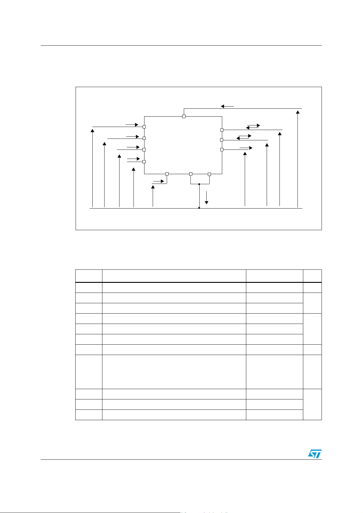
Figure 3. Current and voltage conventions
I
S
V
I
INA
I
INB
I
ENA
I
ENB
V
INA
V
INB
V
ENA
V
ENB
IN
A
IN
B
DIAGA/EN
DIAGB/EN
PWM
I
pw
V
pw
V
CC
OUT
A
OUT
B
A
B
GND
CS
GND
A
B
V
SENSE
I
SENSE
I
V
OUTB
OUTB
I
OUTA
V
OUTA
GND
I
GND
CC
2.1 Absolute maximum ratings
Table 5. Absolute maximum ratings
Symbol Parameter Value Unit
V
I
max
I
R
I
IN
EN
I
pw
V
V
T
T
CC
CS
ESD
j
c
STG
Supply voltage +41 V
Maximum output current (continuous) 30
Reverse output current (continuous) -30
Input current (INA and INB pins) ±10
Enable input current (DIAGA/ENA and DIAGB/ENB pins) ±10
PWM input current ±10
Current sense maximum voltage -3/+15 V
Electrostatic discharge (R = 1.5kΩ, C = 100pF)
–CS pin
– logic pins
– output pins: OUT
, OUTB, V
A
CC
Junction operating temperature Internally limited
Case operating temperature -40 to 150
Storage temperature -55 to 150
A
mAI
2
4
5
kV
kV
kV
°CT
8/33
Page 9
VNH2SP30-E Electrical specifications
2.2 Electrical characteristics
VCC = 9V up to 16 V; -40°C < TJ < 150°C, unless otherwise specified.
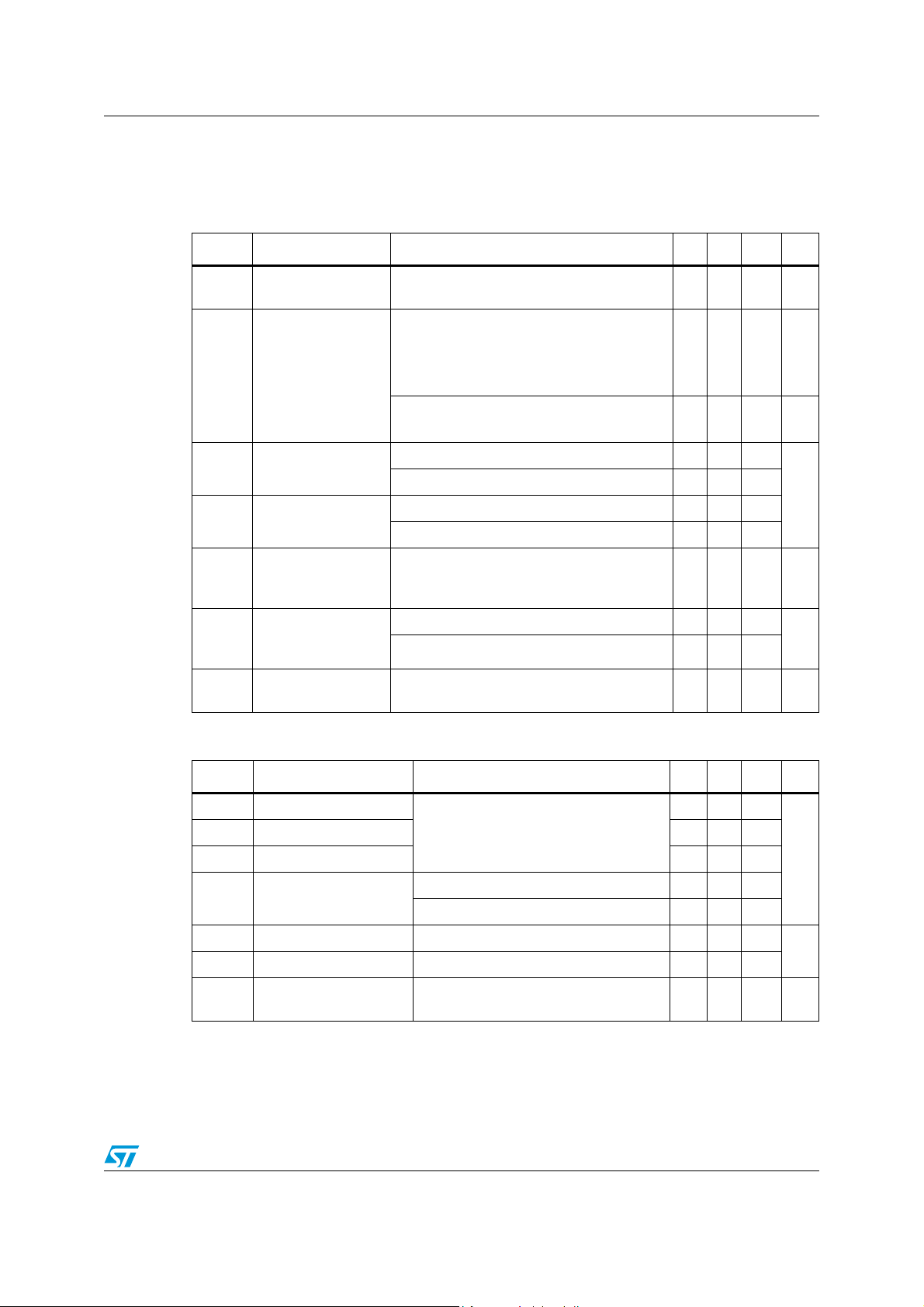
Table 6. Power section
Symbol Parameter Test conditions Min Typ Max Unit
V
CC
Operating supply
voltage
Off state with all Fault Cleared & ENx=0
=INB=PWM=0; Tj= 25°C; VCC=13V
IN
A
=INB=PWM=0
IN
I
S
Supply current
A
Off state: INA=INB=PWM=0
On state:
or INB=5V, no PWM 10 mA
IN
A
= 15A; Tj= 25°C 14
I
R
ONHS
R
ONLS
Static high side
resistance
Static low side
resistance
OUT
I
= 15A; Tj= -40 to 150°C 28
OUT
= 15A; Tj= 25°C 5
I
OUT
= 15A; Tj= -40 to 150°C 10
I
OUT
High side free-
V
f
wheeling diode
= 15A 0.8 1.1 V
I
f
forward voltage
High side off state
I
L(off)
output current
(per channel)
I
RM
Table 7. Logic inputs (INA, INB, ENA, ENB)
Dynamic crossconduction current
Tj=25°C; V
= 125°C; V
T
j
= 15A (see Figure 7)0.7A
I
OUT
=ENX=0V; VCC=13V 3
OUTX
OUTX
5.5 16 V
12230
60
=ENX=0V; VCC=13V 5
µA
µA
mA
mΩ
µA
Symbol Parameter Test conditions Min Typ Max Unit
V
V
V
V
I
I
V
IL
IH
IHYST
ICL
INL
INH
DIAG
Input low level voltage
Input high level voltage 3.25
Normal operation (DIAG
as an input pin)
/ENX pin acts
X
1.25
Input hysteresis voltage 0.5
I
=1mA 5.5 6.3 7.5
Input clamp voltage
IN
= -1mA -1.0 -0.7 -0.3
I
IN
Input low current VIN=1.25V 1
Input high current VIN=3.25V 10
Enable output low level
voltage
Fault operation (DIAGX/ENX pin acts as
an output pin); IEN=1mA
0.4 V
µA
9/33
V
Page 10
Electrical specifications VNH2SP30-E
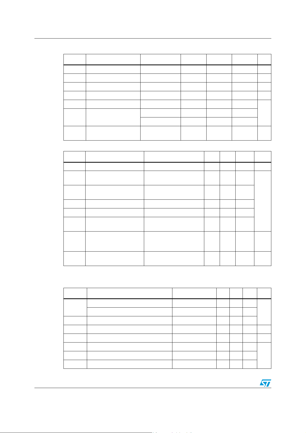
Table 8. PWM
Symbol Parameter Test conditions Min Typ Max Unit
V
pwl
I
pwl
V
pwh
I
pwh
V
pwhhyst
V
pwcl
C
INPWM
Table 9. Switching (VCC=13V, R
PWM low level voltage 1.25 V
PWM pin current Vpw= 1.25V 1 µA
PWM high level voltage 3.25 V
PWM pin current Vpw= 3.25V 10 µA
PWM hysteresis voltage 0.5
I
= 1mA VCC+0.3 VCC+0.7 VCC+1.0
PWM clamp voltage
PWM pin input
capacitance
pw
I
= -1mA -6.0 -4.5 -3.0
pw
V
=2.5V 25 pF
IN
=0.87Ω , unless otherwise specified)
LOAD
Symbol Parameter Test conditions Min Typ Max Unit
f PWM frequency 0 20 kHz
t
d(on)
t
d(off)
t
r
t
f
t
DEL
Turn-on delay time
Turn-off delay time
Rise time (see Figure 5)11.6
Fall time (see Figure 5)1.22.4
Delay time during change
of operating mode
Input rise time < 1µs
(see Figure 6)
Input rise time < 1µs
(see Figure 6)
250
250
(see Figure 4) 300 600 1800
High side free wheeling
t
rr
diode reverse recovery
(see Figure 7)110ns
time
(1)
t
off(min)
1. To avoid false Short to Battery detection during PWM operation, the PWM signal must be low for a time
longer than 6µs.
Table 10. Protection and diagnostic
PWM minimum off time
9V < V
L = 250µH; I
<16V; Tj= 25°C;
CC
OUT
= 15A
6µs
V
µs
Symbol Parameter Test conditions Min Typ Max Unit
Undervoltage shut-down 5.5
V
USD
V
I
V
T
T
LIM
OV
CLP
TSD
TR
HYST
Overvoltage shut-down 16 19 22
High side current limitation 30 50 70 A
Total clamp voltage (VCC to GND) I
Thermal shut-down temperature V
Thermal reset temperature 135
Thermal hysteresis 7 15
10/33
= 15A 43 48 54 V
OUT
= 3.25V 150 175 200
IN
VUndervoltage reset 4.7
°CT
Page 11
VNH2SP30-E Electrical specifications
Table 11. Current sense (9V < V
CC
<16V)
Symbol Parameter Test conditions Min Typ Max Unit
I
= 30A; R
K
1
K
2
dK1/K
dK
2/K2
I
SENSEO
1. Analog sense current drift is deviation of factor K for a given device over (-40°C to 150°C and
9V < V
I
OUT/ISENSE
I
OUT/ISENSE
(1)
Analog sense current drift
1
(1)
Analog sense current drift
Analog sense leakage
current
< 16V) with respect to its value measured at Tj= 25°C, VCC=13V.
CC
OUT
Tj= -40 to 150°C
I
=8A; R
OUT
= -40 to 150°C
T
j
= 30A; R
I
OUT
SENSE
Tj= -40 to 150°C
I
>8A; R
OUT
SENSE
Tj= -40 to 150°C
I
=0A; V
OUT
= -40 to 150°C
T
j
SENSE
SENSE
SENSE
=1.5kΩ;
=1.5kΩ;
=1.5kΩ;
=1.5kΩ;
=0V;
9665 11370 13075
9096 11370 13644
-8 +8
-10 +10
065µA
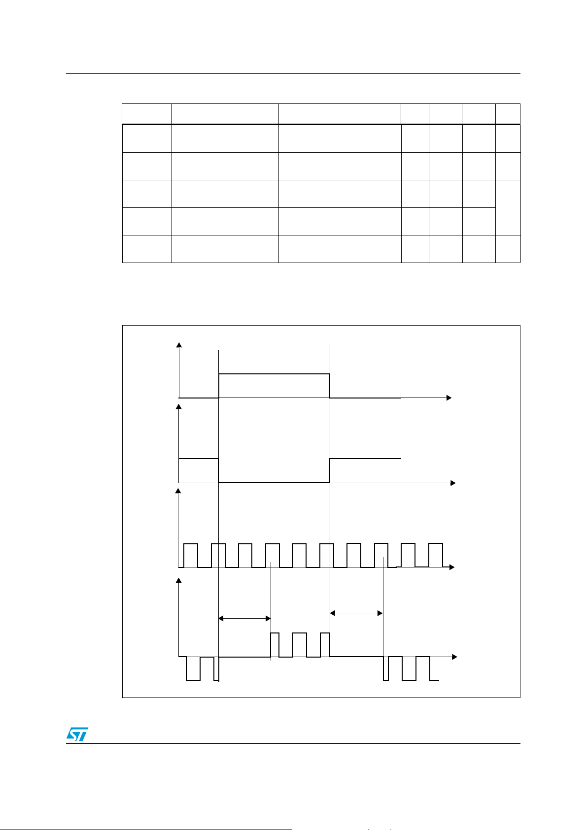
Figure 4. Definition of the delay times measurement
V
INA
%
V
INB
PWM
I
LOAD
t
DEL
t
DEL
t
t
t
t
11/33
Page 12
Electrical specifications VNH2SP30-E
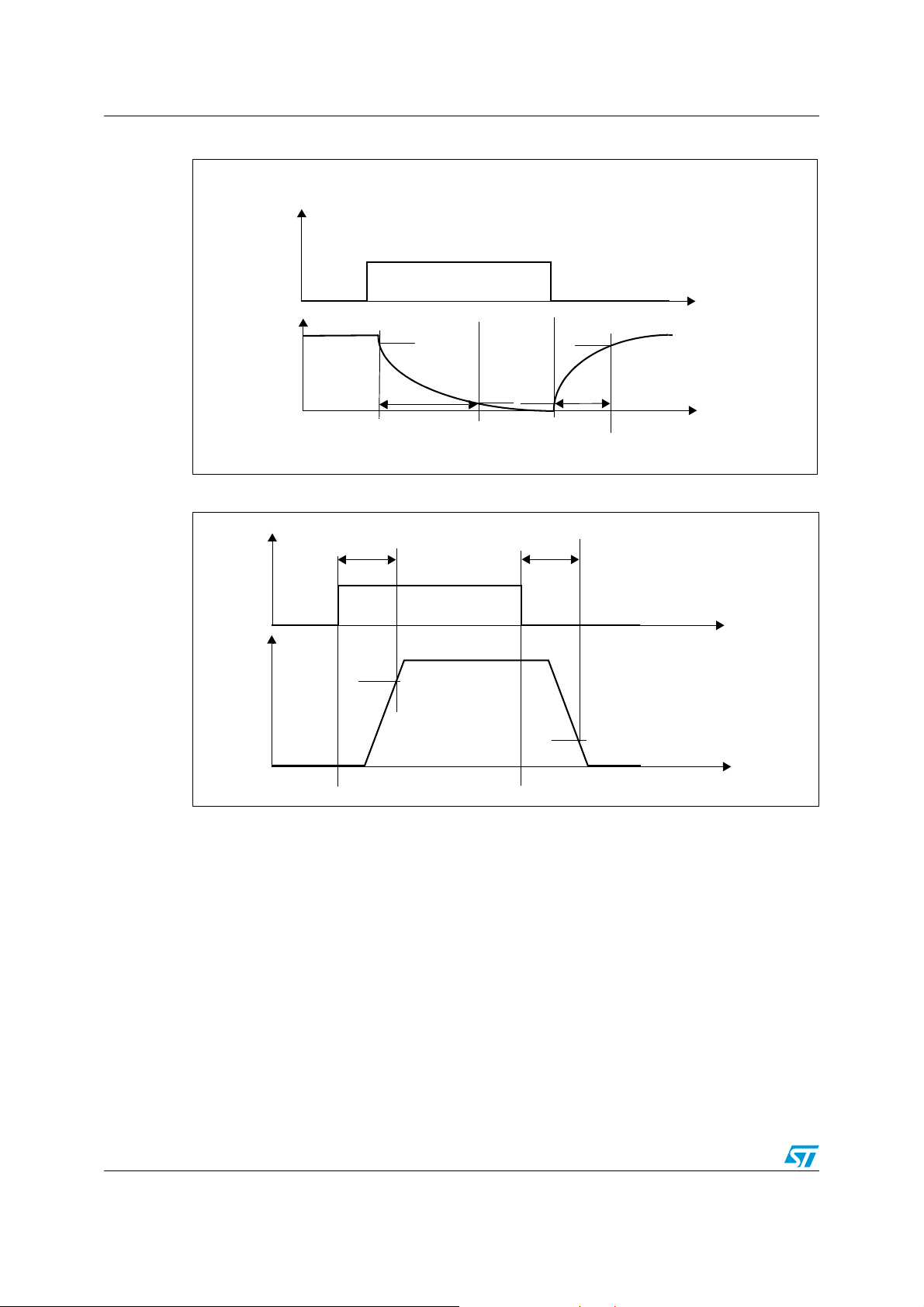
Figure 5. Definition of the low side switching times
PWM
t
V
OUTA, B
90%
80%
t
f
20%
10%
t
r
t
Figure 6. Definition of the high side switching times
V
INA
t
D(on)
t
D(off)
V
t
OUTA
90%
10%
t
12/33
Page 13
VNH2SP30-E Electrical specifications
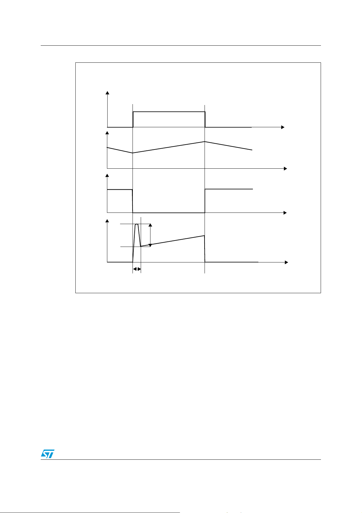
Figure 7. Definition of dynamic cross conduction current during a PWM operation
INA=1, INB=0
PWM
t
I
MOTOR
t
V
OUTB
t
I
CC
I
RM
t
t
rr
13/33
Page 14
Electrical specifications VNH2SP30-E
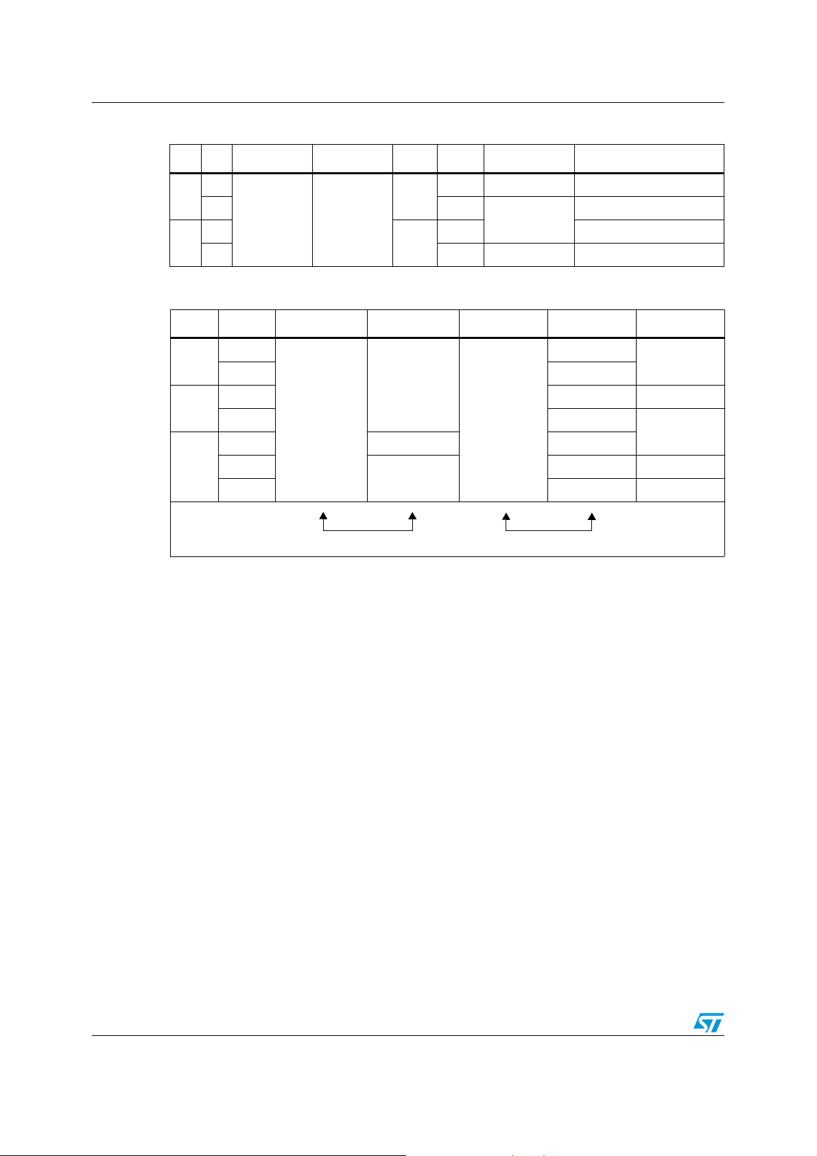
Table 12. Truth table in normal operating conditions
INAINBDIAGA/ENADIAGB/ENBOUTAOUT
1
1
H
H High Imp. Brake to V
B
CS Operating mode
0L
1
0
L
H Counterclockwise (CCW)
11
I
SENSE
=I
OUT
0 L High Imp. Brake to GND
Table 13. Truth table in fault conditions (detected on OUTA)
IN
IN
A
B
DIAGA/EN
A
DIAGB/EN
B
OUT
A
1
1
0L
1
1HI
0
0L
0
OPEN
X 0 OPEN
X
1
1
0 L High Imp.
Fault Information Protection Action
CC
Clockwise (CW)
/K
OUT
B
H
High Imp.
High Imp.
HI
CS
OUTB
OUTB
/K
/K
Note: Notice that saturation detection on the low side power MOSFET is possible only if the
impedance of the short-circuit from the output to the battery is less than 100m
Ω when the
device is supplied with a battery voltage of 13.5V.
14/33
Page 15
VNH2SP30-E Electrical specifications
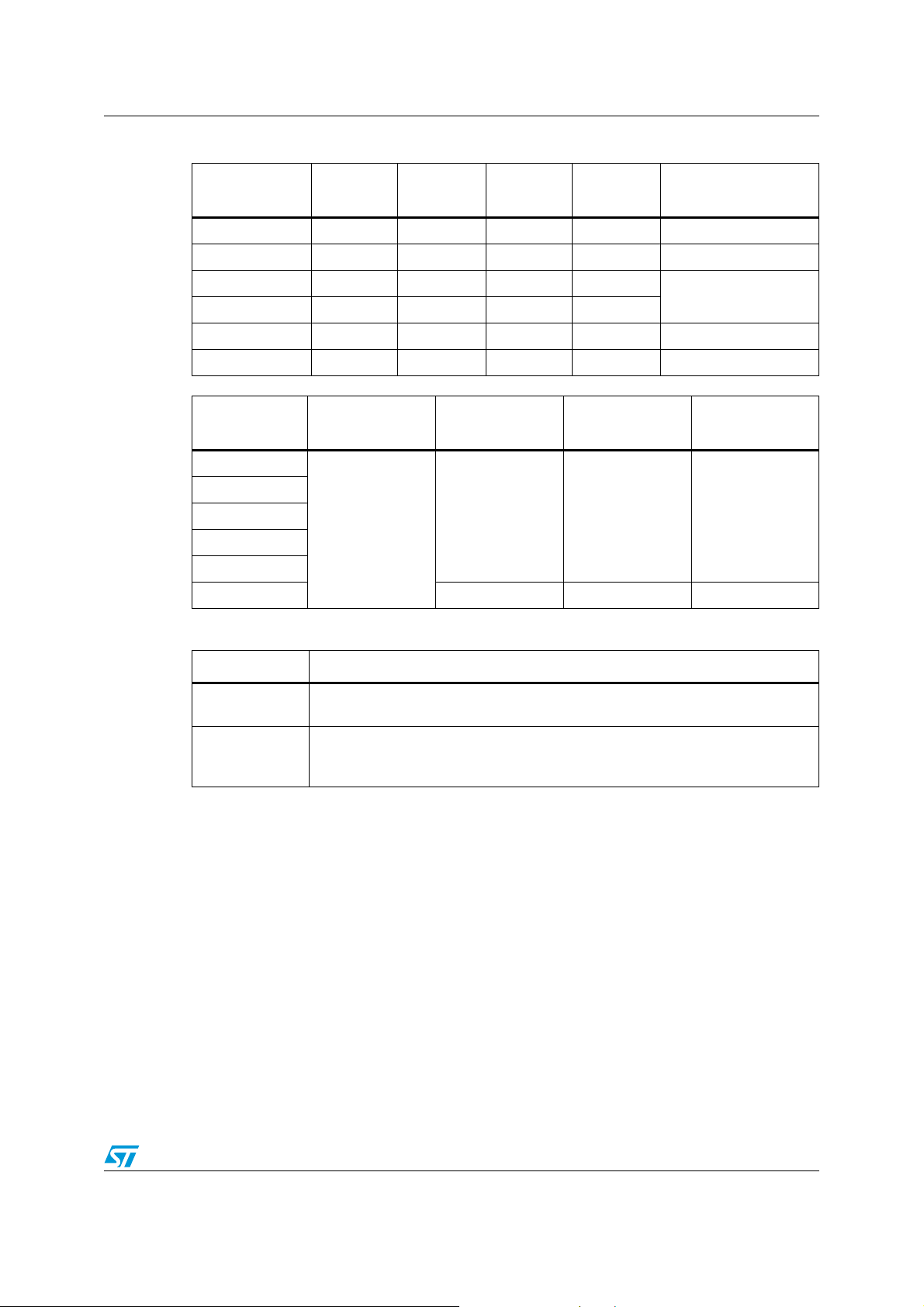
Table 14. Electrical transient requirements
ISO T/R - 7637/1
Tes t puls e
Test LevelITest LevelIITest Level
III
Test Level
IV
delays and impedance
1 -25V -50V -75V -100V 2ms, 10Ω
2 +25V +50V +75V +100V 0.2ms, 10Ω
3a -25V -50V -100V -150V
3b +25V +50V +75V +100V
4 -4V -5V -6V -7V 100ms, 0.01Ω
5 +26.5V +46.5V +66.5V +86.5V 400ms, 2Ω
ISO T/R - 7637/1
test pulse
Test levels
result I
Test levels
result II
Test levels
result III
1
2
3a
CCC
C
3b
4
(1)
5
1. For load dump exceeding the above value a centralized suppressor must be adopted.
EEE
Class Contents
Test levels
0.1µs, 50Ω
Test levels
result IV
C
All functions of the device are performed as designed after exposure to
disturbance.
One or more functions of the device are not performed as designed after
E
exposure to disturbance and cannot be returned to proper operation without
replacing the device.
15/33
Page 16
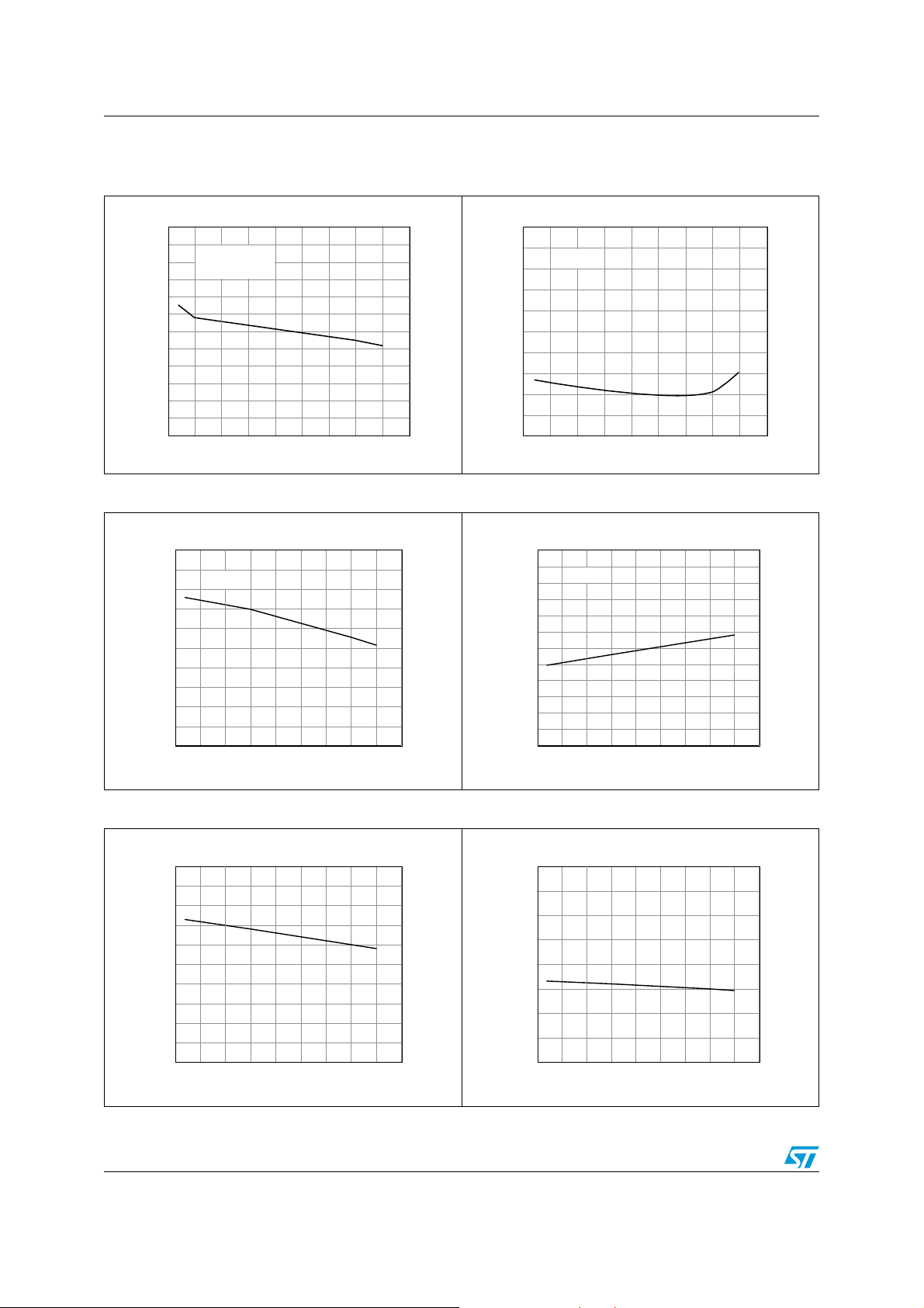
Electrical specifications VNH2SP30-E
2.3 Electrical characteristics curves
Figure 8. On state supply current Figure 9. Off state supply current
Is (mA)
6
5.5
5
4.5
4
3.5
3
2.5
2
1.5
1
0.5
0
-50 -25 0 25 50 75 100 125 150 175
Vcc=13V
INA or INB=5V
Tc ( °C)
Figure 10. High level input current Figure 11. Input clamp voltage
Is (µA)
50
45
40
35
30
25
20
15
10
5
0
Vcc=13V
-50 -25 0 25 50 75 100 125 150 175
Tc (°C)
Iinh (µA)
5
4.5
3.5
2.5
1.5
0.5
Vin=3.25V
4
3
2
1
0
-50 -25 0 25 50 75 100 125 150 175
Tc (° C )
Vicl (V)
8
7.75
7.5
7.25
6.75
6.5
6.25
5.75
5.5
5.25
Iin =1mA
7
6
5
-50 -25 0 25 50 75 100 125 150 175
Tc (° C )
Figure 12. Input high level voltage Figure 13. Input low level voltage
Vih (V)
3
2.9
2.8
2.7
2.6
2.5
2.4
2.3
2.2
2.1
2
-50 -25 0 25 50 75 100 125 150 175
Tc (° C )
Vil (V)
3
2.75
2.5
2.25
2
1.75
1.5
1.25
1
-50 -25 0 25 50 75 100 125 150 175
Tc (° C )
16/33
Page 17
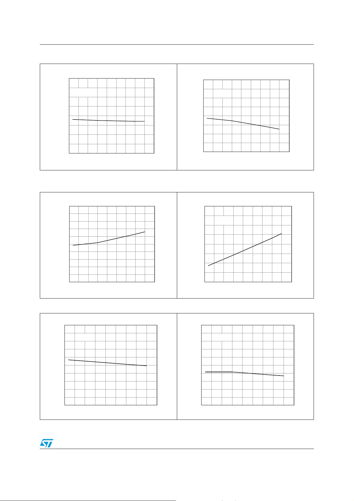
VNH2SP30-E Electrical specifications
Figure 14. Input hysteresis voltage Figure 15. High level enable pin current
Vihyst (V)
2
1.75
1.5
1.25
0.75
0.5
0.25
Vcc=13V
1
0
-50 -25 0 25 50 75 100 125 150 175
Tc (° C )
Figure 16. Delay time during change of
Figure 17. Enable clamp voltage
Ienh (µA)
8
7
Ven=3.25V
6
5
4
3
2
1
0
-50 -25 0 25 50 75 100 125 150 175
Tc ( ° C )
operation mode
tdel (µs)
1000
900
800
700
600
500
400
300
200
100
0
-50 -25 0 25 50 75 100 125 150 175
Tc (°C)
Vencl (V)
-0.2
-0.3
-0.4
-0.5
-0.6
-0.7
-0.8
-0.9
Ien=-1mA
-1
-50 -25 0 25 50 75 100 125 150 175
Tc ( °C)
Figure 18. High level enable voltage Figure 19. Low level enable voltage
Venh (V)
3.6
3.4
3.2
3
2.8
2.6
2.4
2.2
2
1.8
1.6
Vcc=9V
-50 -25 0 25 50 75 100 125 150 175
Tc ( °C)
Venl (V)
3
2.8
2.6
2.4
2.2
2
1.8
1.6
1.4
1.2
1
Vcc=9V
-50 -25 0 25 50 75 100 125 150 175
Tc (°C)
17/33
Page 18
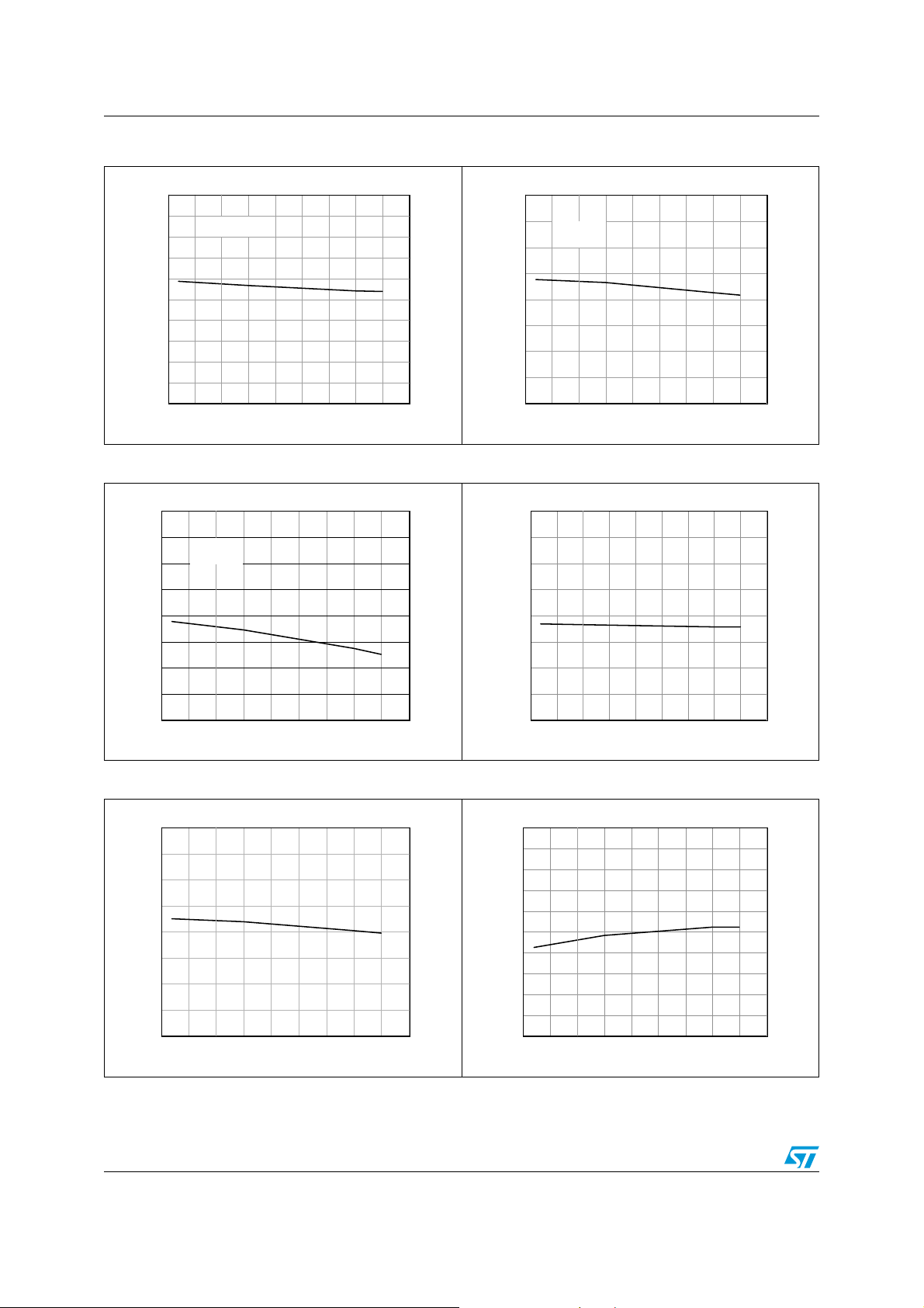
Electrical specifications VNH2SP30-E
Figure 20. PWM high level voltage Figure 21. PWM low level voltage
Vpwh (V)
5
4.5
4
3.5
3
2.5
2
1.5
1
0.5
0
Vcc=9V
-50 -25 0 25 50 75 100 125 150 175
Tc ( °C)
Vpwl (V)
2.6
2.4
2.2
2
1.8
1.6
1.4
1.2
Vcc=9V
1
-50 -25 0 25 50 75 100 125 150 175
Tc (°C)
Figure 22. PWM high level current Figure 23. Overvoltage shutdown
Ipwh (µA)
8
7
6
5
4
3
2
1
0
Vcc=9V
Vpw=3.25V
-50 -25 0 25 50 75 100 125 150 175
Tc (°C)
Vov (V)
30
27.5
25
22.5
20
17.5
15
12.5
10
-50 -25 0 25 50 75 100 125 150 175
Tc (° C)
Figure 24. Undervoltage shutdown Figure 25. Current limitation
Vusd(V)
8
7
6
5
4
3
2
1
0
-50 -25 0 25 50 75 100 125 150 175
Tc (°C)
18/33
Ilim (A)
80
75
70
65
60
55
50
45
40
35
30
-50 -25 0 25 50 75 100 125 150 175
Tc (°C)
Page 19
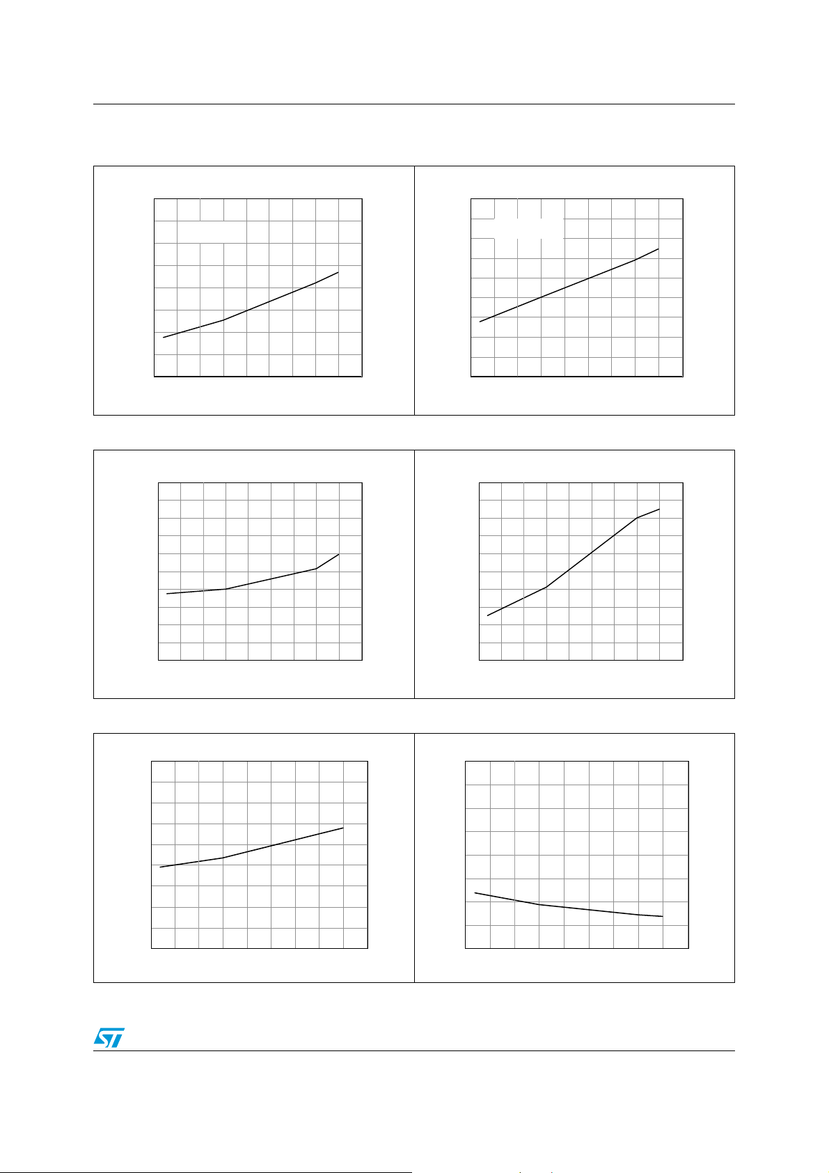
VNH2SP30-E Electrical specifications
Figure 26. On state high side resistance vs
T
case
Ronhs (mOhm)
40
35
30
25
20
15
10
5
0
Vcc=9V; 16V
Iout=15A
-50 -25 0 25 50 75 100 125 150 175
Tc ( °C)
Figure 27. On state low side resistance vs
T
case
Ronls (mOhm)
9
8
7
6
5
4
3
2
1
0
Vcc=9V; 16V
Iout=15A
-50 -25 0 25 50 75 100 125 150 175
Tc (°C)
Figure 28. Turn-On delay time Figure 29. Turn-Off delay time
td(on) (µs)
260
240
220
200
180
160
140
120
100
80
60
-50 -25 0 25 50 75 100 125 150 175
Tc ( °C)
td(off) (µs)
200
190
180
170
160
150
140
130
120
110
100
-50 -25 0 25 50 75 100 125 150 175
Tc (°C)
Figure 30. Output voltage rise time Figure 31. Output voltage fall time
tr (µs)
2
1.8
1.6
1.4
1.2
1
0.8
0.6
0.4
0.2
-50 -25 0 25 50 75 100 125 150 175
Tc ( °C)
tf (µs)
8
7
6
5
4
3
2
1
0
-50 -25 0 25 50 75 100 125 150 175
Tc (°C)
19/33
Page 20
Application information VNH2SP30-E
3 Application information
In normal operating conditions the DIAGX/ENX pin is considered as an input pin by the
device. This pin must be externally pulled high.
PWM pin usage: in all cases, a “0” on the PWM pin will turn off both LS
When PWM rises back to “1”, LS
or LSB turn on again depending on the input pin state.
A
and LSB switches.
A
Figure 32. Typical application circuit for DC to 20 kHz PWM operation short circuit
protection
V
CC
Reg 5V
μ
C
33nF
1K
DIAG
1K
10K
3.3K
1K
1.5K
/EN
A
PWM
+ 5V
V
CC
DIAGB/EN
A
HS
A
OUT
IN
A
CS
LS
A
A
OUT
B
HS
LS
B
IN
B
M
GND
A
100K
S
G
b) N MOSFET
D
GND
+5V
3.3K
B
B
1K
1K
C
B
Note:
The value of the blocking capacitor (C) depends on the application conditions and defines voltage and current ripple onto supply
line at PWM operation. Stored energy of the motor inductance may fly back into the blocking capacitor, if the bridge driver goes into
tri-state. This causes a hazardous overvoltage if the capacitor is not big enough. As basic orientation, 500µF per 10A load current is
recommended.
In case of a fault condition the DIAGX/ENX pin is considered as an output pin by the
device.The fault conditions are:
● overtemperature on one or both high sides
● short to battery condition on the output (saturation detection on the low side power
MOSFET)
Possible origins of fault conditions may be:
● OUT
● OUT
20/33
is shorted to ground → overtemperature detection on high side A.
A
is shorted to V
A
→ low side power MOSFET saturation detection.
CC
Page 21
VNH2SP30-E Application information
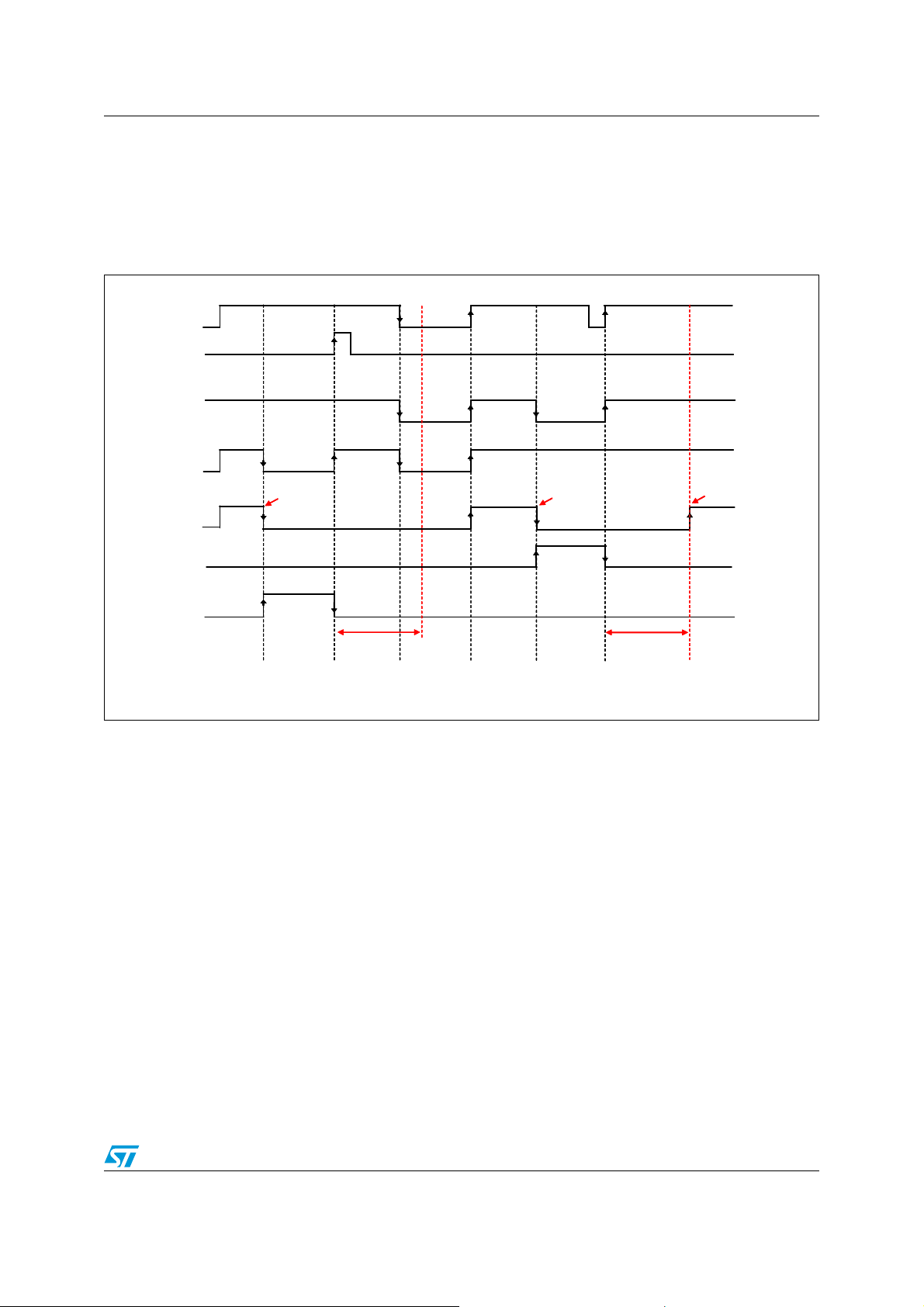
When a fault condition is detected, the user can know which power element is in fault by
monitoring the IN
, INB, DIAGA/ENA and DIAGB/ENB pins.
A
In any case, when a fault is detected, the faulty leg of the bridge is latched off. To turn on the
respective output (OUT
) again, the input signal must rise from low to high level.
X
Figure 33. Behavior in fault condition (How a fault can be cleared)
IN
IN
A
A
IN
IN
B
B
DIAG
DIAG
A
A
EN
EN
A
A
DIAG
DIAG
B
B
EN
EN
B
B
Device Unlatched
Device Unlatched
IoutAÆ out
IoutAÆ out
Device Latched
Device Latched
Device Latched
B
B
Device Latched
FAULT
FAULT
A
A
(Internal Signal)
(Internal Signal)
FAULT
FAULT
B
B
(Internal Signal)
(Internal Signal)
Operation
Operation
Normal
Normal
OUT
OUT
shorted
shorted
B
B
to V
to V
CC
CC
t
t
DEL
DEL
Fault Cleared Stby (*)
Fault Cleared Stby (*)
Normal
Normal
Operation
Operation
OUT
OUT
shorted
shorted
B
B
to GND
to GND
t
t
DEL
DEL
Fault Cleared
Fault Cleared
Normal
Normal
Operation
Operation
Note: In case of the fault condition is not removed, the procedure for unlatching and sending the
device in Stby mode is:
- Clear the fault in the device (toggle : INA if ENA=0 or INB if ENB=0)
- Pull low all inputs, PWM and Diag/EN pins within tDEL.
If the Diag/En pins are already low, PWM=0, the fault can be cleared simply toggling the
input. The device will enter in stby mode as soon as the fault is cleared.
3.1 Reverse battery protection
Three possible solutions can be considered:
1. a Schottky diode
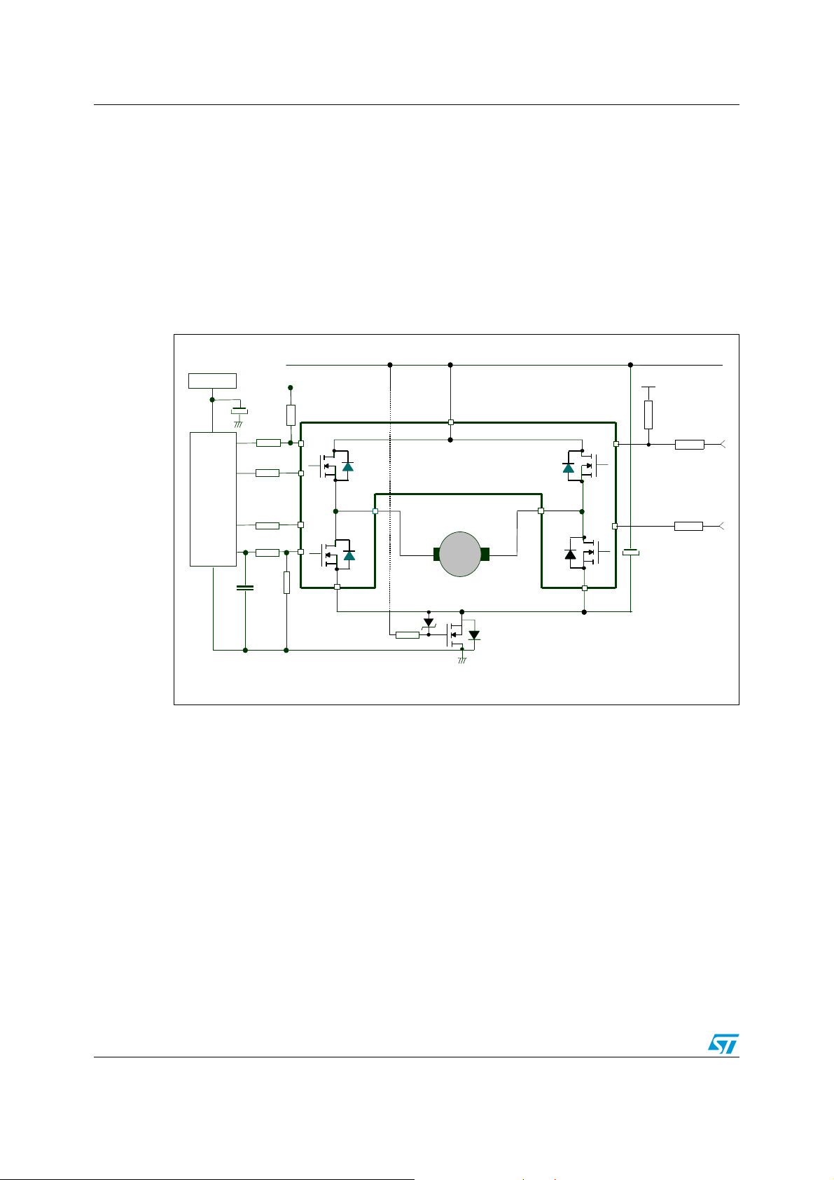
2. an N-channel MOSFET connected to the GND pin (see Figure 32: Typical application
circuit for DC to 20 kHz PWM operation short circuit protection on page 20)
3. a P-channel MOSFET connected to the V
The device sustains no more than -30A in reverse battery conditions because of the two
body diodes of the power MOSFETs. Additionally, in reverse battery condition the I/Os of
VNH2SP30-E are pulled down to the V
D
connected to VCC pin
CC
pin
CC
line (approximately -1.5V). A series resistor must
21/33
Page 22
Application information VNH2SP30-E
be inserted to limit the current sunk from the microcontroller I/Os. If I
is the maximum
Rmax
target reverse current through µC I/Os, the series resistor is:
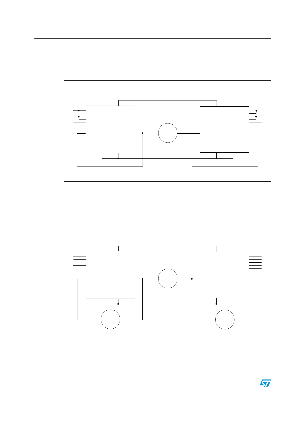
Figure 34. Half-bridge configuration
V
CC
DIAG
/EN
A
DIAGB/EN
PWM
OUT
GND
B
IN
A
IN
B
A
B
B
IN
A
IN
B
DIAG
/EN
A
DIAGB/EN
PWM
OUT
A
GND
A
B
OUT
B
GND
A
B
M
OUT
A
GND
A
Note: The VNH2SP30-E can be used as a high power half-bridge driver achieving an On
resistance per leg of 9.5mΩ.
Figure 35. Multi-motors configuration
V
CC
DIAG
DIAGB/EN
GND
B
3
/EN
A
PWM
OUT
IN
A
IN
B
A
B
B
IN
A
IN
B
/EN
DIAG
A
DIAGB/EN
PWM
OUT
A
GND
A
B
A
M
GND
1
B
OUT
B
M
2
OUT
A
GND
A
M
Note: The VNH2SP30-E can easily be designed in multi-motors driving applications such as seat
positioning systems where only one motor must be driven at a time. DIAG
/ENX pins allow
X
to put unused half-bridges in high impedance.
22/33
Page 23
VNH2SP30-E Application information
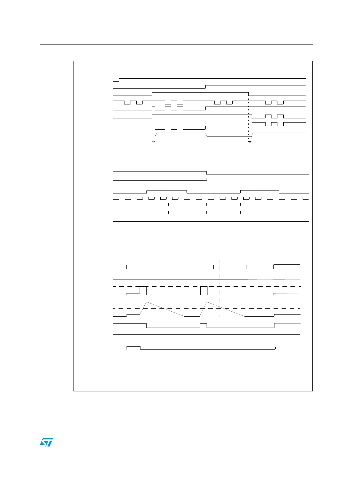
Figure 36. Waveforms in full bridge operation
NORMAL OPERATION (DIAGA/ENA=1, DIAGB/ENB=1)
DIAGA/EN
DIAGB/EN
IN
A
IN
B
A
B
LOAD CONNECTED BETWEEN OUTA, OUT
PWM
OUT
A
OUT
I
OUTA->OUTB
B
CS (*)
t
(*) CS BEHAVIOR DURING PWM MODE WILL DEPEND ON PWM FREQUENCY AND DUTY CYCLE.
DEL
NORMAL OPERATION (DIAGA/ENA=1, DIAGB/ENB= 0 and DIAGA/ENA=0, DIAGB/ENB=1)
LOAD CONNECTED BETWEEN OUTA, OUT
DIAGA/EN
DIAGB/EN
IN
IN
PWM
OUT
OUT
I
OUTA->OUTB
CS
A
B
A
B
A
B
B
t
DEL
B
CURRENT LIMITATION/THERMAL SHUTDOWN or OUTA SHORTED TO GROUND
IN
A
IN
B
I
OUTA->OUTB
T
j
DIAGA/EN
DIAGB/EN
CS
I
LIM
A
B
normal operation
shorted to ground
OUT
A
Tj > T
TR
normal operation
T
TSD
T
TR
23/33
Page 24
Application information VNH2SP30-E
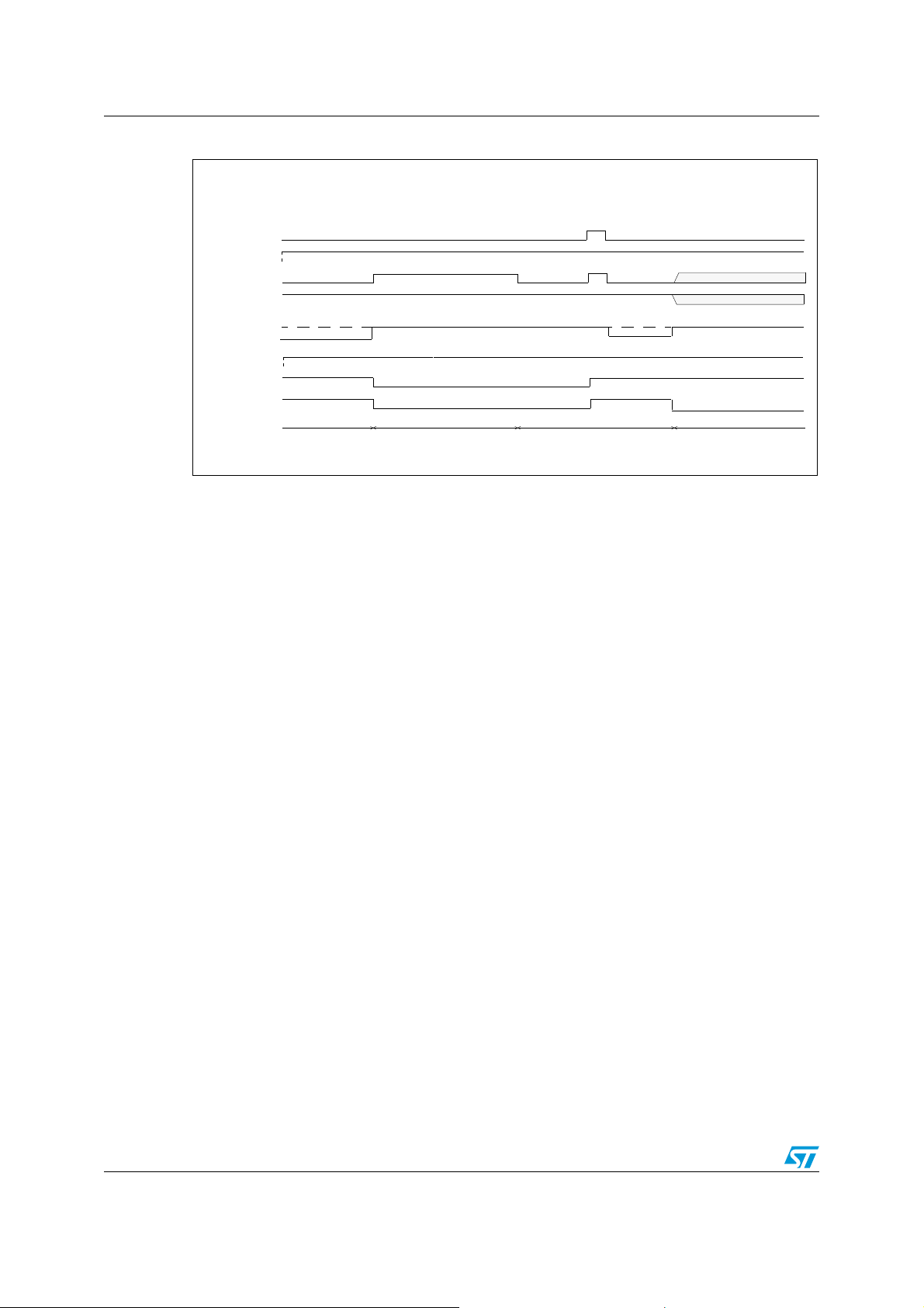
Figure 37. Waveforms in full bridge operation (continued)
OUTA shorted to VCC and undervoltage shutdown
IN
A
IN
B
OUT
A
OUT
B
I
OUTA->OUTB
undefined
undefined
DIAGB/EN
DIAGA/EN
CS
B
A
normal
operation
OUT
V < nominal
shorted to V
A
CC
normal operation
undervoltage shutdown
24/33
Page 25
VNH2SP30-E Package and PCB thermal data
4 Package and PCB thermal data
4.1 PowerSSO-30 thermal data
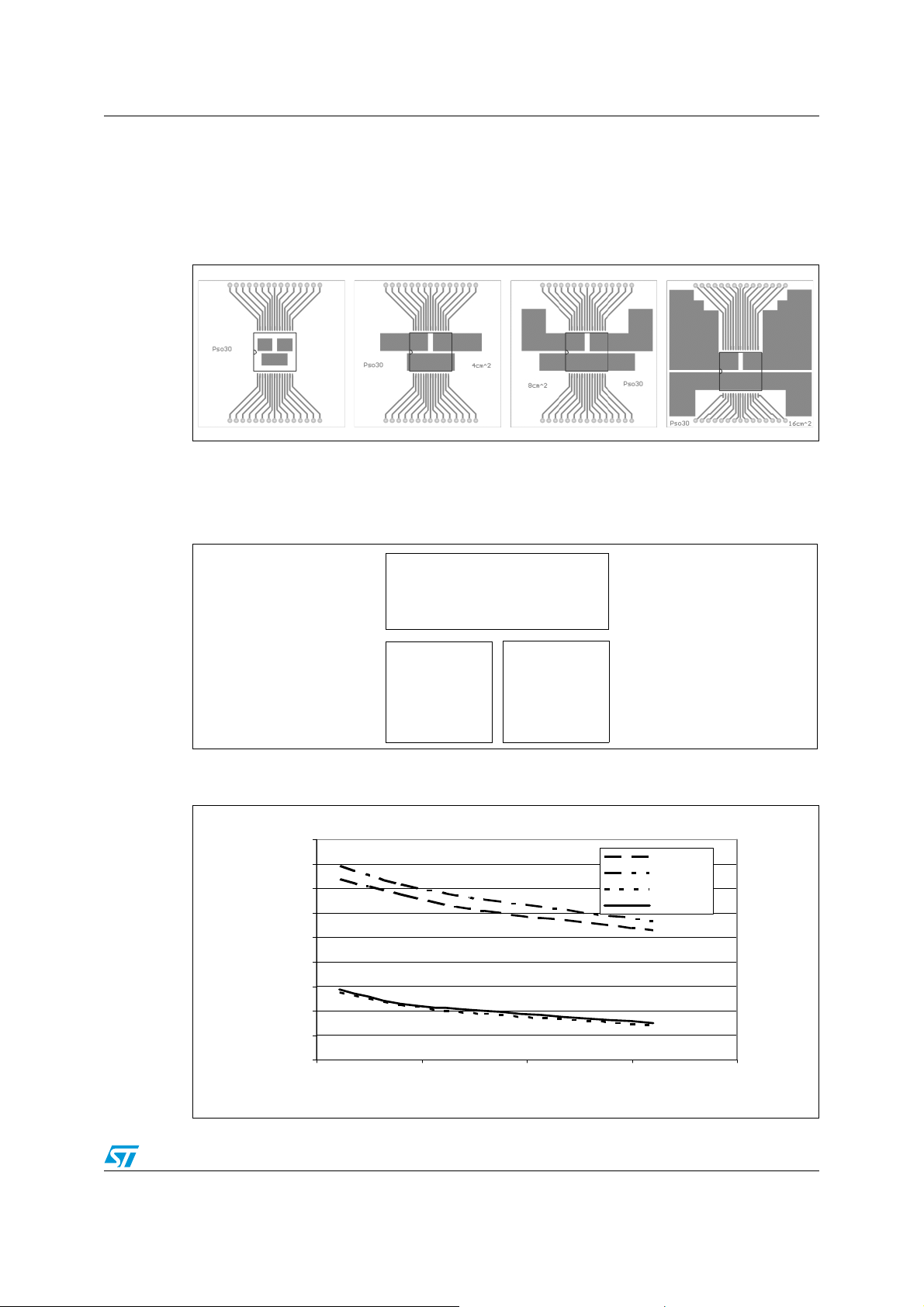
Figure 38. MultiPowerSO-30™ PC board
Note: Layout condition of R
thickness = 2mm. Cu thickness = 35μm, Copper areas: from minimum pad layout to
2
16cm
).
Figure 39. Chipset configuration
Figure 40. Auto and mutual R
condition
45
40
35
30
25
20
15
10
°C/W
5
0
0 5 10 15 20
and Zth measurements (PCB FR4 area = 58mm x 58mm, PCB
th
HIGH SIDE
CHIP
HS
AB
LOW SIDE
CHIP A
LS
A
vs PCB copper area in open box free air
thj-amb
cm2 of Cu area (refer to PCB layout)
LOW SIDE
CHIP B
LS
B
RthHS
RthLS
RthHSLS
RthLSLS
25/33
Page 26
Package and PCB thermal data VNH2SP30-E
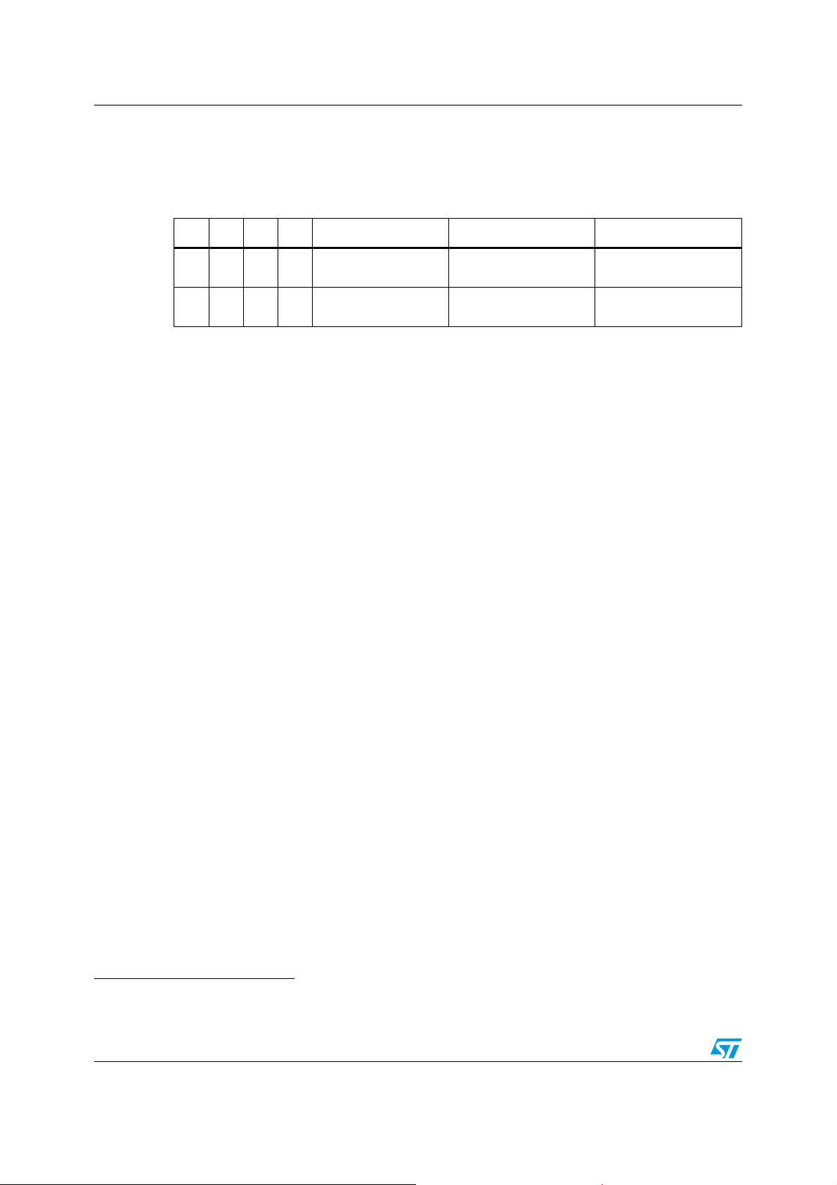
4.1.1 Thermal calculation in clockwise and anti-clockwise operation in steady-state mode
Table 15. Thermal calculation in clockwise and anti-clockwise operation in steady-
state mode
HSAHSBLSALS
ON OFF OFF ON
OFF ON ON OFF
B
P
x R
P
x R
dHSA
thHSLS
dHSB
thHSLS
T
x R
x R
jHSAB
thHS
+ T
thHS
+ T
+ P
amb
+ P
amb
dLSB
dLSA
T
jLSA
P
x R
dHSA
P
x R
dLSB
P
x R
dHSB
P
x R
dLSA
thHSLS
thLSLS
thHSLS
+ T
thLS
+
+ T
+
amb
amb
P
x R
P
x R
dHSA
dHSB
x R
+ T
thLS
x R
thLSLS
T
jLSB
thHSLS
amb
thHSLS
+ T
amb
+ P
+ P
dLSB
dLSA
4.1.2 Thermal resistances definition (values according to the PCB heatsink area)
R
= R
thHS
HS
in ON state)
B
R
= R
thLS
R
thHSLS
between High Side and Low Side Chips
R
thLSLS
Chips
4.1.3 Thermal calculation in transient mode
T
T
T
jHSAB
jLSA
jLSB
= Z
= Z
= Z
thHSA
thLSA
= R
= R
thHS
thHSLS
thHSLS
= R
= R
thLSB
thHSALSB
thLSALSB
x P
dHSAB
x P
x P
= High Side Chip Thermal Resistance Junction to Ambient (HSA or
thHSB
= Low Side Chip Thermal Resistance Junction to Ambient
= R
thHSBLSA
= Mutual Thermal Resistance Junction to Ambient
= Mutual Thermal Resistance Junction to Ambient between Low Side
(a)
dHSAB
dHSAB
+ Z
+ Z
+ Z
thHSLS
x P
thLS
thLSLS
x (P
dLSA
x P
dLSA
+ Z
dLSA
+ P
thLSLS
+ Z
dLSB
thLS
) + T
x P
x P
amb
dLSB
dLSB
+ T
+ T
amb
amb
4.1.4 Single pulse thermal impedance definition (values according to the PCB heatsink area)
Z
= High Side Chip Thermal Impedance Junction to Ambient
thHS
Z
= Z
thLS
Z
thHSLS
between High Side and Low Side Chips
Z
thLSLS
Chips
a. Calculation is valid in any dynamic operating condition. Pd values set by user.
26/33
thLSA
= Z
thHSABLSA
= Z
thLSALSB
= Z
= Low Side Chip Thermal Impedance Junction to Ambient
thLSB
= Z
thHSABLSB
= Mutual Thermal Impedance Junction to Ambient
= Mutual Thermal Impedance Junction to Ambient between Low Side
Page 27
VNH2SP30-E Package and PCB thermal data
Equation 1: pulse calculation formula
Z
THδ
where
R
TH
δ Z
THtp
1 δ–()+Þ=
δ tpT⁄=
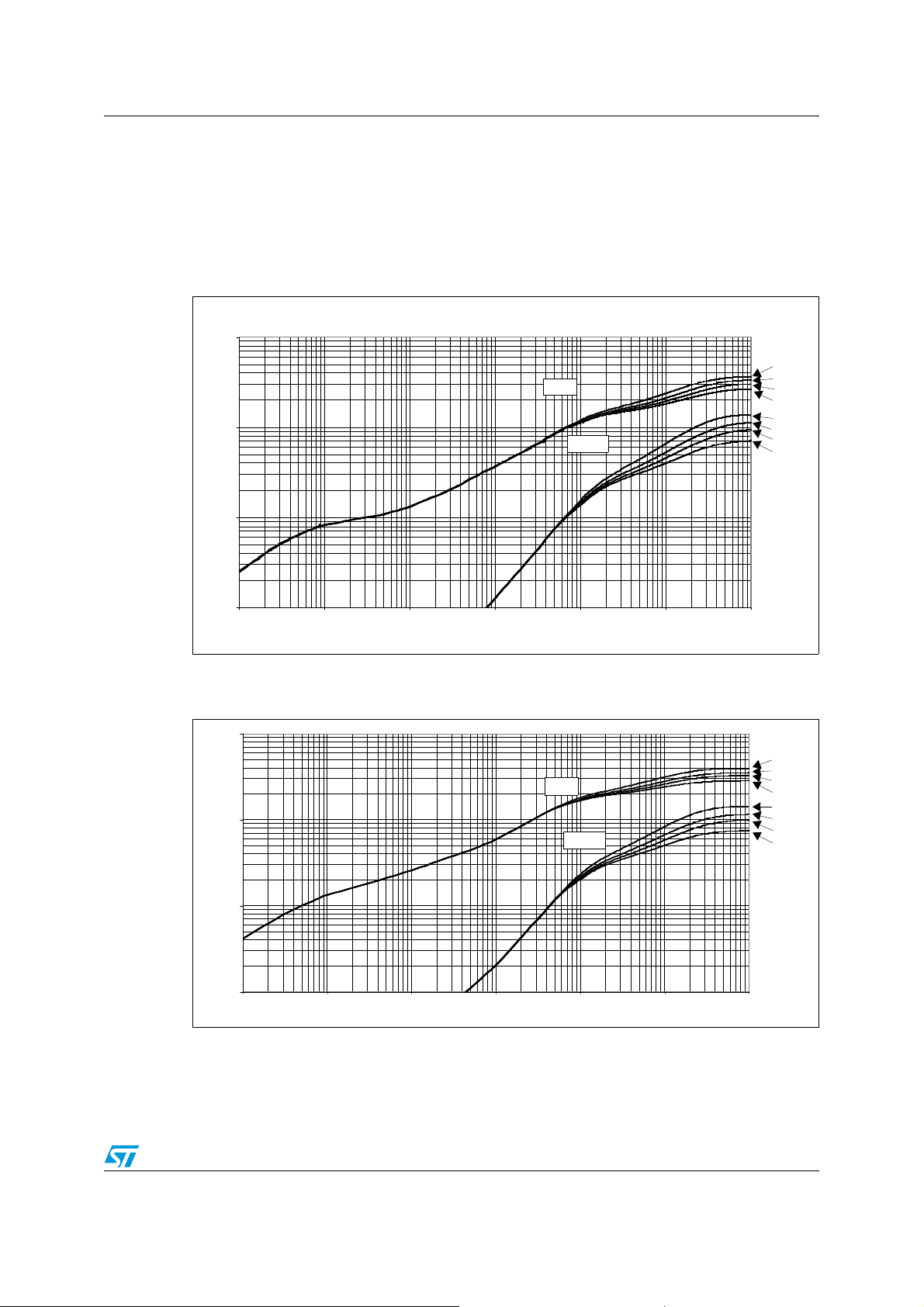
Figure 41. MultiPowerSO-30 HSD thermal impedance junction ambient single pulse
100
Footprint
ZthHS
10
ZthHSLS
°C/W
1
4 cm2
8 cm2
16 cm2
Footprint
4 cm2
8 cm2
16 cm2
0.1
0.001 0.01 0.1 1 10 100 1000
tim e (sec)
Figure 42. MultiPowerSO-30 LSD thermal impedance junction ambient single pulse
100
Footpr int
4 cm2
ZthLS
10
ZthLSLS
°C/W
1
0.1
0.001 0.01 0.1 1 10 100 1000
tim e (sec)
8 cm2
16 cm2
Footpr int
4 cm2
8 cm2
16 cm2
27/33
Page 28
Package and PCB thermal data VNH2SP30-E
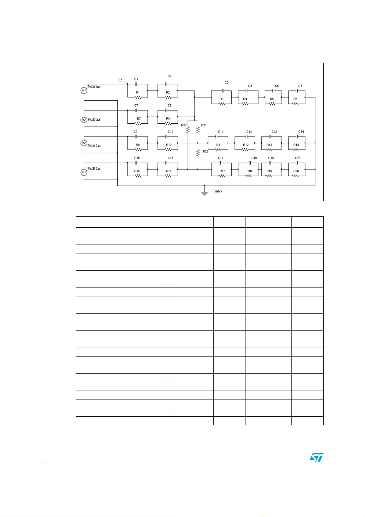
Figure 43. Thermal fitting model of an H-bridge in MultiPowerSO-30
Table 16. Thermal parameters
(1)
Area/island (cm2)Footprint4 8 16
R1 = R7 (°C/W) 0.05
R2 = R8 (°C/W) 0.3
R3 (°C/W) 0.5
R4 (°C/W) 1.3
R5 (°C/W) 14
R6 (°C/W) 44.7 39.1 31.6 23.7
R9 = R15 (°C/W) 0.2
R10 = R16 (°C/W) 0.4
R11 = R17 (°C/W) 0.8
R12 = R18 (°C/W) 1.5
R13 = R19 (°C/W) 20
R14 = R20 (°C/W) 46.9 36.1 30.4 20.8
R21 = R22 = R23 (°C/W) 115
C1 = C7 (W.s/°C) 0.005
C2 = C8 (W.s/°C) 0.008
C3 = C11 = C17 (W.s/°C) 0.01
C4 = C13 = C19 (W.s/°C) 0.3
C5 (W.s/°C) 0.6
C6 (W.s/°C) 5 7 9 11
C9 = C15 (W.s/°C) 0.003
C10 = C16 (W.s/°C) 0.006
C12 = C18 (W.s/°C) 0.075
C14 = C20 (W.s/°C) 2.5 3.5 4.5 5.5
1. The blank space means that the value is the same as the previous one.
28/33
Page 29
VNH2SP30-E Package and packing information
5 Package and packing information
5.1 ECOPACK® packages
In order to meet environmental requirements, ST offers these devices in ECOPACK®
packages. ECOPACK
is marked on the package and on the inner box label, in compliance with JEDEC Standard
JESD97. The maximum ratings related to soldering conditions are also marked on the inner
box label.
ECOPACK is an ST trademark. ECOPACK specifications are available at www.st.com.
®
packages are lead-free. The category of Second Level Interconnect
5.2 MultiPowerSO-30 package mechanical data
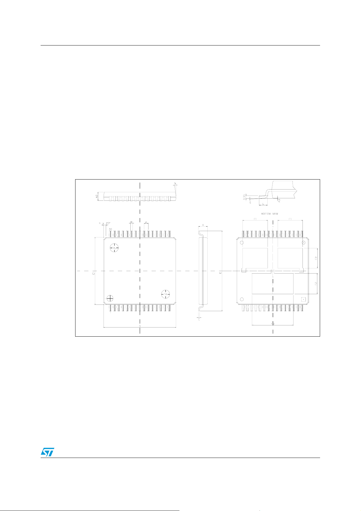
Figure 44. MultiPowerSO-30 package outline
29/33
Page 30
Package and packing information VNH2SP30-E
Table 17. MultiPowerSO-30 mechanical data
Symbol
Min Typ Max
A 2.35
A2 1.85 2.25
A3 0 0.1
B 0.42 0.58
C 0.23 0.32
D 17.1 17.2 17.3
E 18.85 19.15
E1 15.9 16 16.1
e1
F1 5.55 6.05
F2 4.6 5.1
Millimeters
F3 9.6 10.1
L 0.8 1.15
N 10deg
S 0deg 7deg
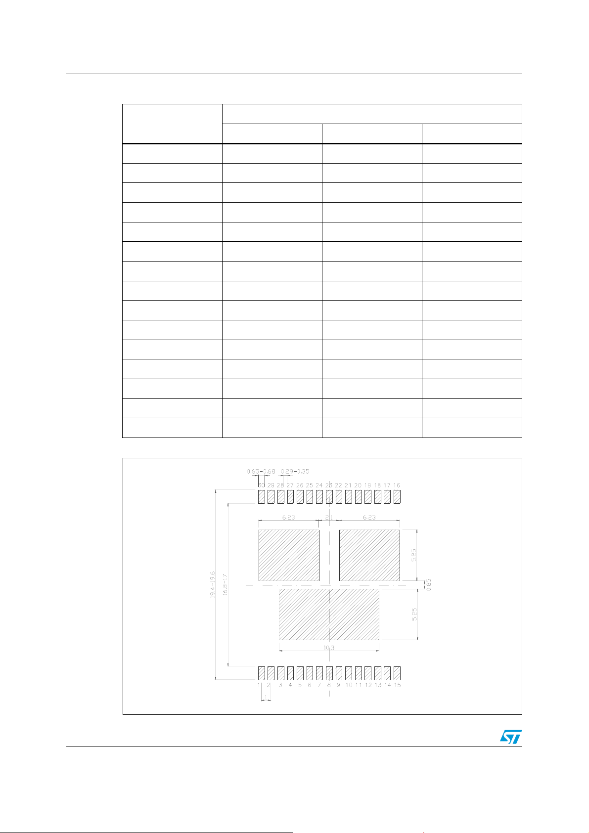
Figure 45. MultiPowerSO-30 suggested pad layout
30/33
Page 31
VNH2SP30-E Package and packing information
5.3 Packing information
Note: The devices can be packed in tube or tape and reel shipments (see the Device summary on
page 1 for packaging quantities).
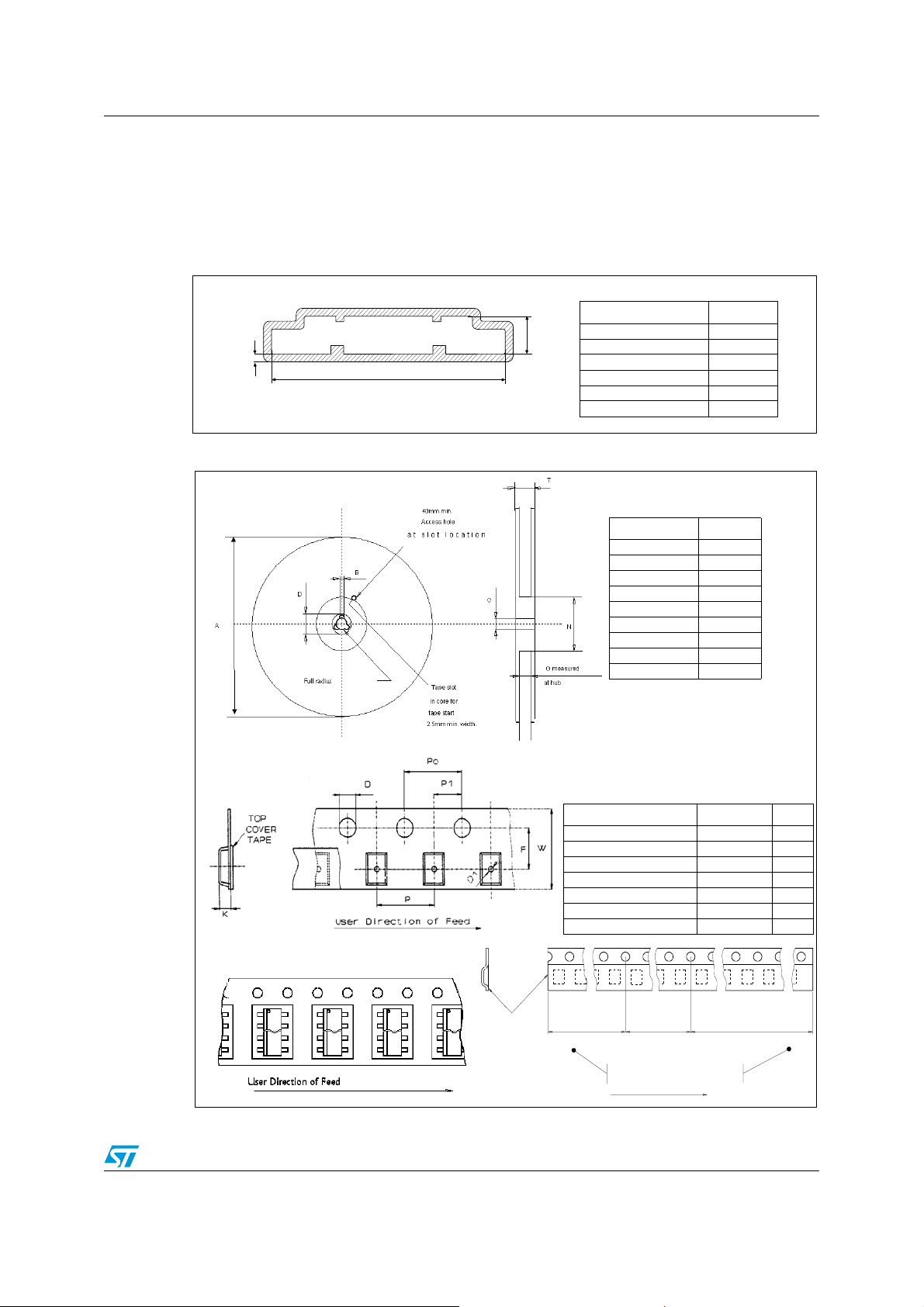
Figure 46. MultiPowerSO-30 tube shipment (no suffix)
Dimension mm
A
C
B
Figure 47. MultiPowerSO-30 tape and reel shipment (suffix “TR”)
Base Q.ty 29
Bulk Q.ty 435
Tube length (± 0.5) 532
A3.82
B23.6
C (± 0.13) 0.8
Reel dimensions
SO-28 tube shipment (no suffix)
Dimension mm
Base Q.ty 1000
Bulk Q.ty 1000
A (max) 330
B (min) 1.5
C (± 0.2) 13
D (min) 20.2
G (+ 2 / -0) 32
N (min) 100
T (max) 38.4
Tape dimensions
According to Electronic Industries Association
(EIA) Standard 481 rev. A, Feb 1986
Description Dimension mm
Tape width W 32
Tape Hole Spacing P0 (± 0.1) 4
Component Spacing P 24
Hole Diameter D (± 0.1/-0) 1.5
Hole Diameter D1 (min) 2
Hole Position F (± 0.1) 14.2
Compartment Depth K (max) 2.2
End
Start
To p
cover
tape
500 mm min
Empty components pockets
User direction of feed
No componentsNo components Components
500 mm min
31/33
Page 32
Revision history VNH2SP30-E
6 Revision history
Table 18. Document revision history
Date Revision Description of changes
Sep-2004 1 First issue
Dec- 2004 2
Inserted t
Modified IRM figure number
test condition modification and note
off(min)
Feb-2005 3 Minor changes
Apr-2005 4 Public release
Document converted into new ST corporate template.
Added table of contents, list of tables and list of figures
Removed figure number from package outline on page 1
Changed Features on page 1 to add ECOPACK
®
package
Added Section 1: Block diagram and pin description on page 5
Added Section 2.2: Electrical characteristics on page 9
01-Sep-2006 5
Added “low” and “high” to parameters for I
INL
and I
page 9
Inserted note in Figure 32 on page 20
Added vertical limitation line to left side arrow of
in Ta b l e 7 o n
INH
t
to Figure 7 on
D(off)
page 13
Added Section 4.1: PowerSSO-30 thermal data on page 25
Added Section 5: Package and packing information on page 29
Added Section 5.3: Packing information on page 31
Updated disclaimer (last page) to include a mention about the use of
ST products in automotive applications
15-May-2007 6 Document reformatted and converted into new ST template.
06-Feb-2008 7
Corrected Heat Slug numbers in Table 3: Pin definitions and
functions.
Added new infomation in Table 6: Power section
02-Oct-2008 8
Added Figure 33: Behavior in fault condition (How a fault can be
cleared)
32/33
Page 33

VNH2SP30-E
Please Read Carefully:
Information in this document is provided solely in connection with ST products. STMicroelectronics NV and its subsidiaries (“ST”) reserve the
right to make changes, corrections, modifications or improvements, to this document, and the products and services described herein at any
time, without notice.
All ST products are sold pursuant to ST’s terms and conditions of sale.
Purchasers are solely responsible for the choice, selection and use of the ST products and services described herein, and ST assumes no
liability whatsoever relating to the choice, selection or use of the ST products and services described herein.
No license, express or implied, by estoppel or otherwise, to any intellectual property rights is granted under this document. If any part of this
document refers to any third party products or services it shall not be deemed a license grant by ST for the use of such third party products
or services, or any intellectual property contained therein or considered as a warranty covering the use in any manner whatsoever of such
third party products or services or any intellectual property contained therein.
UNLESS OTHERWISE SET FORTH IN ST’S TERMS AND CONDITIONS OF SALE ST DISCLAIMS ANY EXPRESS OR IMPLIED
WARRANTY WITH RESPECT TO THE USE AND/OR SALE OF ST PRODUCTS INCLUDING WITHOUT LIMITATION IMPLIED
WARRANTIES OF MERCHANTABILITY, FITNESS FOR A PARTICULAR PURPOSE (AND THEIR EQUIVALENTS UNDER THE LAWS
OF ANY JURISDICTION), OR INFRINGEMENT OF ANY PATENT, COPYRIGHT OR OTHER INTELLECTUAL PROPERTY RIGHT.
UNLESS EXPRESSLY APPROVED IN WRITING BY AN AUTHORIZED ST REPRESENTATIVE, ST PRODUCTS ARE NOT
RECOMMENDED, AUTHORIZED OR WARRANTED FOR USE IN MILITARY, AIR CRAFT, SPACE, LIFE SAVING, OR LIFE SUSTAINING
APPLICATIONS, NOR IN PRODUCTS OR SYSTEMS WHERE FAILURE OR MALFUNCTION MAY RESULT IN PERSONAL INJURY,
DEATH, OR SEVERE PROPERTY OR ENVIRONMENTAL DAMAGE. ST PRODUCTS WHICH ARE NOT SPECIFIED AS "AUTOMOTIVE
GRADE" MAY ONLY BE USED IN AUTOMOTIVE APPLICATIONS AT USER’S OWN RISK.
Resale of ST products with provisions different from the statements and/or technical features set forth in this document shall immediately void
any warranty granted by ST for the ST product or service described herein and shall not create or extend in any manner whatsoever, any
liability of ST.
ST and the ST logo are trademarks or registered trademarks of ST in various countries.
Information in this document supersedes and replaces all information previously supplied.
The ST logo is a registered trademark of STMicroelectronics. All other names are the property of their respective owners.
© 2008 STMicroelectronics - All rights reserved
STMicroelectronics group of companies
Australia - Belgium - Brazil - Canada - China - Czech Republic - Finland - France - Germany - Hong Kong - India - Israel - Italy - Japan -
Malaysia - Malta - Morocco - Singapore - Spain - Sweden - Switzerland - United Kingdom - United States of America
www.st.com
33/33
 Loading...