

Page 1
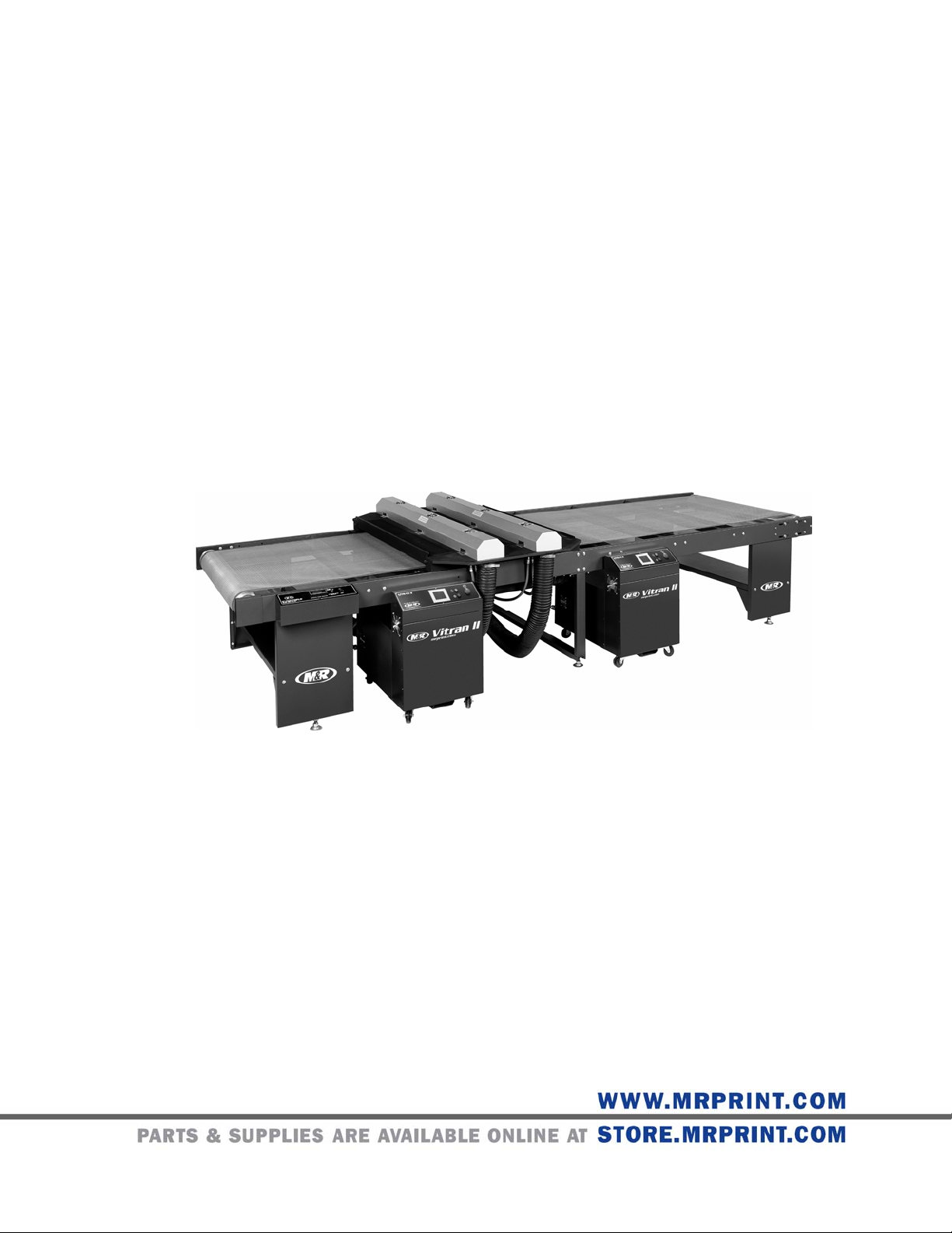
V.112910 Part # MAN-VITRAN II Vitran II Hv1
™
$45.00 USD
Vitran II
Page 2

™
Vitran II
V.112910
This page intentionally left blank
2 M&R Companies 1N 372 Main St. Glen Ellyn, IL 60137 USA
Tel: +630-858-6101 Fax: +630-858-6134 www.mrprint.com | store.mrprint.com
Page 3

V.112910 Vitran II™
Table of Contents
1.
Safety and Operational Guidelines...........................................................................................................................5
1.1 Management Responsibilities...................................................................................................................................6
1.2 Operator Responsibilities..........................................................................................................................................7
2. General Information....................................................................................................................................................8
2.1 Service and Parts......................................................................................................................................................9
2.2 Defined Purpose ............................................................................................................................... ......................10
2.3 Warranty..................................................................................................................................................................10
3. Product Specifications.............................................................................................................................................11
4. Assembly and Installation .......................................................................................................................................15
4.1 Assembly.................................................................................................................................................................15
4.1.1 UV Lamp Installation and Replacement ..........................................................................................................18
4.2 Installation...............................................................................................................................................................18
5. Operation...................................................................................................................................................................19
5.1 Dryer Control Panel.................................................................................................................................................19
5.1.1 Operator Interface............................................................................................................................................19
5.2 Conveyor Control Panel..........................................................................................................................................25
5.3 Principles of UV Curing...........................................................................................................................................26
5.4 Operation Overview ................................................................................................................................................27
5.4.1 Lamp Focus.....................................................................................................................................................27
5.5 Dryer Startup/Shutdown..........................................................................................................................................27
6. Scheduled Maintenance...........................................................................................................................................30
6.1 Scheduled Maintenance Log...................................................................................................................................34
7. Troubleshooting........................................................................................................................................................35
8. Replacement Parts ...................................................................................................................................................36
M&R Companies 1N 372 Main St. Glen Ellyn, IL 60137 USA 3
Tel: +630-858-6101 Fax: +630-858-6134 www.mrprint.com | store.mrprint.com
Page 4

™
Vitran II
V.112910
This page intentionally left blank
4 M&R Companies 1N 372 Main St. Glen Ellyn, IL 60137 USA
Tel: +630-858-6101 Fax: +630-858-6134 www.mrprint.com | store.mrprint.com
Page 5
V.112910 Vitran II™
1. Safety and Operational Guidelines
DANGER
The product described in this publication may operate at high speed and contain numerous
Energy Sources
Danger From
Compressed Air
(Pneumatic
Energy)
This symbol identifies situations that endanger people, property, and/or equipment. If such
conditions exist, the equipment must be shut down and all energy sources (electrical, gas, and
pneumatic) must be disconnected, purged, and locked out until the problem is resolved.
Never attempt to bypass or defeat any safety device. Do not attempt to operate the equipment if
any safety device is not functioning properly, or if any doubt exists about proper operation of safety
devices.
moving parts. It may employ natural gas or propane, mechanical or pneumatic forces, and/or
hazardous voltages, and may create other conditions that could, through misuse, abuse,
unauthorized alteration or retrofitting, inattention, or lack of understanding, result in injury, death, or
damage to the product or to other equipment. In addition, improper operation may also depreciate
the value of the machine and other assets of the owner, and impair the working efficiency of the
machine.
M&R equipment may use one of more of the following energy sources:
• Compressed Air (Pneumatic Energy)
• Electricity
• Gas (Natural Gas or Propane)
Each form of energy presents its own unique hazards and requires appropriate precautions.
Only qualified personnel should be allowed to work on pneumatic components or assemblies. Before
work is started on pneumatic components or assemblies, equipment should be disconnected from the
air supply and all pneumatic lines should be purged to prevent accidental operation of pneumatic
assemblies. All pneumatic pipes and hoses should be checked frequently for da mage and wear.
Danger From
Electrical
Energy
WARNING
M&R Companies 1N 372 Main St. Glen Ellyn, IL 60137 USA 5
Tel: +630-858-6101 Fax: +630-858-6134 www.mrprint.com | store.mrprint.com
Only qualified personnel should have access to electrical enclosures or work on electrical systems,
and enclosures should be locked when not in use. Electrical equipment should be checked regularly.
Failure to follow safety and maintenance procedures or to take appropriate corrected action when
required can result in severe or fatal personal injuries, property damage, and/or damage to the
equipment.
Page 6

™
Vitran II
V.112910
1.1 Management Responsibilities
Management
Responsibilities
1. Ensure that this equipment is used only for the purposes set forth in the “Defined Purpose”
section of this manual.
2. Ensure that all employees involved with the operation of this equipment or working near it read,
understand, and act in accordance with the operational and safety standards set forth in this
manual, including the Operator Responsibilities listed below.
3. Ensure that all recommended preventive maintenance is carried out according to M&R
guidelines.
4. Should any problem arise which compromises the safe operation or normal functioning of this
equipment, ensure that the equipment is immediately shut down, sources of power to the
equipment is shut off and secured, and that personnel not trained to repair – and directly involved
in repairing – the equipment are removed from the immediate area and not allowed to return until
the equipment has been returned to a safe and fully-functional condition.
5. Provide, and compel use of, any personal protection devices that may be required for the safe
operation of this equipment.
6. Make no modification to equipment or equipment software without written approval from M&R.
7. Provide – and support with written documentation – necessary employee training to ensure safe
operation, including but not limited to instruction in:
a. the operation of this machine
b. the use of personal protection devices
c. preventive maintenance procedures
6 M&R Companies 1N 372 Main St. Glen Ellyn, IL 60137 USA
Tel: +630-858-6101 Fax: +630-858-6134 www.mrprint.com | store.mrprint.com
Page 7

V.112910 Vitran II™
1.2 Operator Responsibilities
Operator
Responsibilities
Note: ‘Operator Responsibilities’ pertain to all employees who work on or near the equipment; this includes, but
is not limited to those who clean, maintain and repair the equipment as well as those who operate it. In
general, all those who work on or near the equipment have a duty to use reasonable and ordinary care
for their own safety when in the vicinity of the machine. Failure to use reasonable and ordinary care
subjects people and property to serious personal injury and/or death and to destruction of personal
and/or company property. M&R expressly disclaims any and all liability, whether in contract, tort or by
statute, for damages, whether in the nature of personal injury/death and/or property damage, and
whether direct, indirect, consequential or incidental, as a result of a failure to use reasonable and
ordinary care.
1. Ensure that this equipment is used only for the purposes set forth in the “Defined Purpose”
section of this manual.
2. Read, understand, and act in accordance with the safety and operational standards and
guidelines set forth in this manual.
3. Install and maintain the equipment and safety devices in accordance with this manual; this
includes checking the equipment and safety devices for external or visible damage at least once
per shift, and making sure all safety and danger notices are in place and in readable condition.
4. Make no modification to equipment or equipment software without written approval from M&R.
5. Ensure that all other employees working on or near this equipment are knowledgeable in its safe
operation, and closely supervise inexperienced employees; keep bystanders away from the
equipment.
6. Make sure the area around the equipment is clear and free of obstructions, cle an up spills
immediately, and remove ink and other contaminants at the end of each shift.
7. Ensure that any and all safety guards (including but not limited to safety bar, foot switch, yellow
cycle interruption cords, infrared safety beam or hand switches) provided with this equipment for
the purpose of protecting personnel by automatically stopping the equipment are in place – and
are not removed, disabled or rendered ineffective during operation.
8. Wear any personal protection devices required for the safe operation of this equipment.
9. Avoid wearing anything that could become entangled in moving parts; for example, but not by
way of limitation, tie back, pin up, or cover long hair.
10. Do not attempt to operate this equipment if you are sick, fatigued, or under the influence of
alcohol and/or drugs including, but not limited to, prescriptions and over-the-counter medications
that warn against the operation of equipment.
11. Avoid standing on any part of the equipment not intended for that purpose.
12. Immediately shut down the equipment, disconnect and lock out all sources of power (electrical,
gas, and/or pneumatic); and purge all lines under pressure if the equipment fails to be fully
operational or if any safety device fails to operate properly, and ensure that the equipment stays
offline until the safety device is again operational.
13. Perform – and document – preventive maintenance at intervals described in the Operator’s
Manual.
14. Keep this Operator’s Manual in clean, easily readable condition near the equipment at all times
so it can be quickly accessed by operators and maintenance personnel.
M&R Companies 1N 372 Main St. Glen Ellyn, IL 60137 USA 7
Tel: +630-858-6101 Fax: +630-858-6134 www.mrprint.com | store.mrprint.com
Page 8

™
Vitran II
V.112910
2. General Information
This Document
This document is based on information available at the time of its publication. While every effort has
been made to be accurate, the information contained herein does not purport to cover all details or
variations in hardware, software, features, or specifications, or to provide for every possible
contingency in connection with installation, operation and maintenance. Features may be described
herein which are not present in all models of this product. M&R Printing Equipment, Inc. and its
subsidiaries reserve the right to alter specifications in the manufacture of their products, and they
assume no obligation of notice to holders of this document with respect to changes subsequently
made.
M&R Printing Equipment, Inc. and its subsidiaries make no representation or warranty, expressed or
implied, whether pursuant to statute or case law with respect thereto, and assume no responsibility
for, the accuracy, completeness, sufficiency or usefulness of the information contained herein. No
warranties of merchantability or fitness for a particular purpose shall apply.
This is a publication of M&R Printing Equipment, Inc. and its subsidiaries. All information contained
herein is derived in part from proprietary and patent data of M&R Printing Equipment, Inc., and may
not be copied, electronically reproduced, or transmitted in any form without prior written permission, in
each case made and provided.
8 M&R Companies 1N 372 Main St. Glen Ellyn, IL 60137 USA
Tel: +630-858-6101 Fax: +630-858-6134 www.mrprint.com | store.mrprint.com
Page 9
V.112910 Vitran II™
2.1 Service and Parts
Manufacturer’s
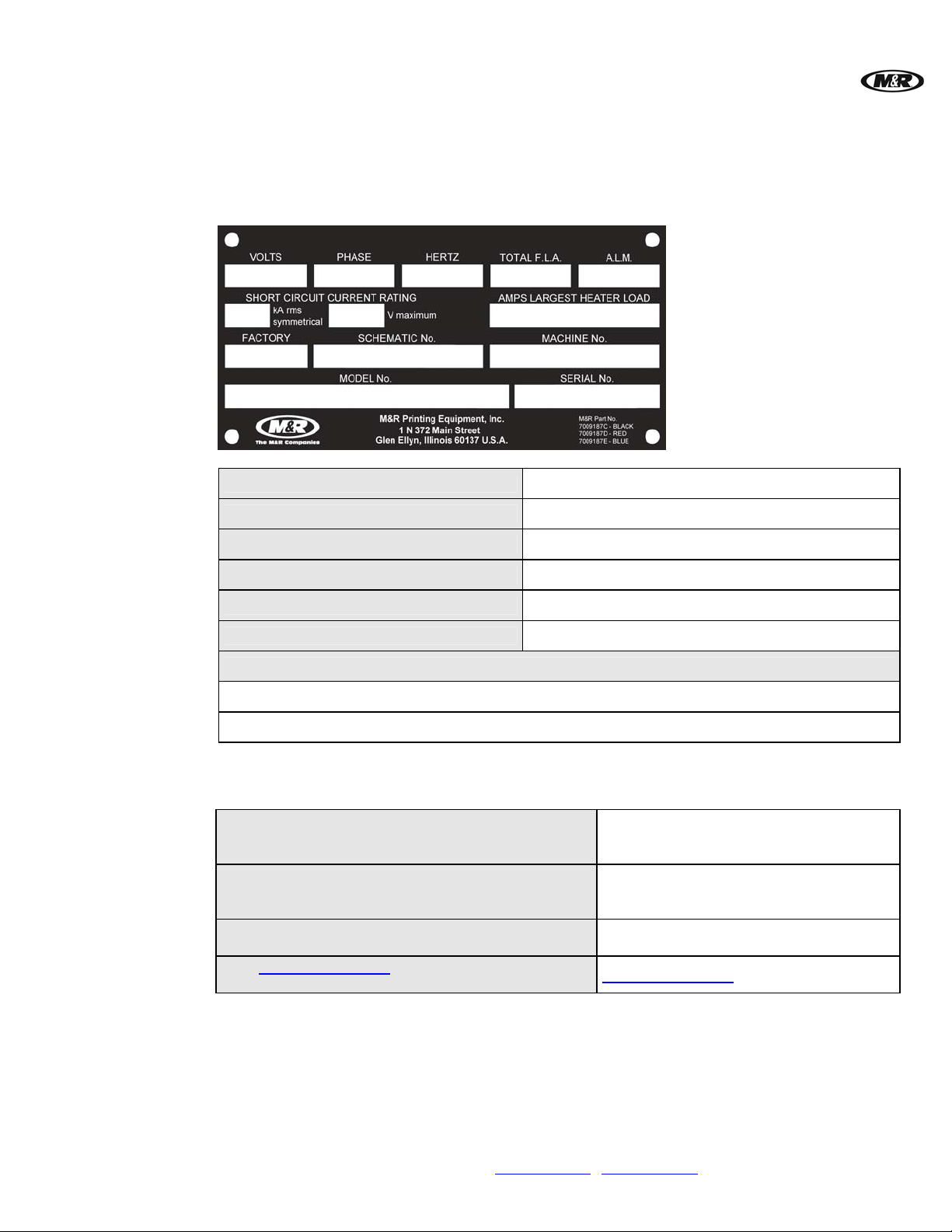
Rating Plate
Most products manufactured by the M&R Companies carry a metal manufacturer’s rating plate simila r
to the one shown below. Please use it to fill out the product information below, and be prepared to
provide the identification information when calling. This helps us respond to your needs more quickly.
Contacting M&R
Model No.
Machine No.
Serial No.
Schematic No.
Date Installed
Installed by
Optional Features and Special Information
If you need service or have questions about your equipment, call the appropriate number and ask for
Technical Support. If you need parts, ask for the Parts Department.
From the United States & Canada
Monday-Friday between 8:30 AM and 5:00 PM
Central Standard/Daylight Time
800-736-6431
Or
630-858-6101
From all other countries
Monday-Friday between 14:30 and 23:00 Greenwich
+847-967-4461
Mean Time (GMT)
Outside Regular Hours
Visit www.mrprint.com for a list of global
contacts
Call our Global Hotline:
+630-462-4715
www.mrprint.com
M&R Companies 1N 372 Main St. Glen Ellyn, IL 60137 USA 9
Tel: +630-858-6101 Fax: +630-858-6134 www.mrprint.com | store.mrprint.com
Page 10

™
Vitran II
V.112910
2.2 Defined Purpose
Textile Presses
Textile Dryers
Graphic Presses
Graphic Dryers
Exposure
Equipment
Folding and
Packaging
Equipment
Ancillary
Equipment
Textile Presses are designed to print textile inks on textile substrates, as more fully set forth in the
manual specific to that product. Any other use of this equipment is not permitted.
Textile Dryers are designed to cure/dry textile inks on textile substrates, as more fully set forth in the
manual specific to that product. Any other use of this equipment is not permitted.
Graphic Presses are designed to print graphic inks on rigid and semi-rigid flat substrates, as more
fully set forth in the manual specific to that product. Any other use of this equipment is not permitted.
Graphic Dryers are designed to cure/dry graphic inks on rigid and semi-rigid flat substrates, as more
fully set forth in the manual specific to that product. Any other use of this equipment is not permitted.
Exposure Equipment is designed to produce photographic printing plates and printing screens, as
more fully set forth in the manual specific to that product. Any other use of this equipment is not
permitted.
Folding and Packaging Equipment is designed to fold, transport, and package textile materials, as
more fully set forth in the manual specific to that product. Any other use of this equipment is not
permitted.
Ancillary Equipment is designed to perform specific operations related to processing and handling of
substrates, as more fully set forth in the manual specific to that product. Any other use of this
equipment is not permitted.
2.3 Warranty
Limited
Warranty
Your Warranty does not apply to damages sustained due to equipment misuse, whether inte ntional or
negligent, and such misuse may void your warranty. Misuse includes – but is not limited to – the
items listed below. In addition, M&R Printing Equipment, Inc. accepts no responsibility for personal
injury or property damage caused by misuse.
1. Use of the equipment for any non-defined purpose
2. Improper installation or use of the equipment
3. Operation of the equipment with defective safety devices
4. Operation of the equipment with safety devices removed, disabled, not working in whole or in part
or in any manner rendered ineffective for the purpose for which they were designed
5. Failure to comply with instructions for transportation, storage, installation, operation,
maintenance, setup, and take-down of the equipment as described in the Operator’s Manual
6. Unauthorized modification of the equipment or equipment software
7. Failure to replace worn or defective parts
8. Failure to use M&R supplied replacement and repair parts
9. Defective repairs made to the equipment
10. Dangerous conditions which result from improper use of the equipment
10 M&R Companies 1N 372 Main St. Glen Ellyn, IL 60137 USA
Tel: +630-858-6101 Fax: +630-858-6134 www.mrprint.com | store.mrprint.com
Page 11
V.112910 Vitran II™
3. Product Specifications
Specifications
Lamp & Belt Width
Belt Length
Lamps
Electrical
Requirements @
118 watts /cm
(300 watts / in)
1
Electrical
Requirements @
157 watts /cm
(400 watts / in)
Shipping Weight
1
Vitran II 24-10
Vitran II 24-15-2 Vitran II 30-10 Vitran II 30-15-2
61 cm (24") 61 cm (24") 76 cm (30") 76 cm (30")
305 cm (10') 457 cm (15') 305 cm (10') 457 cm (15')
1 2 1 2
208/230 V, 1 ph, 51/48 A,
50/60 Hz, 11 kW
208/230 V, 3 ph, 49/45 A,
50/60 Hz, 10.5 kW
400 V, 3 ph, 30 A,
50 Hz, 10.5 kW
460 V, 3 ph, 23 A,
50/60 Hz, 10.5 kW
208/230 V, 1 ph, 65/61 A,
50/60 Hz, 14 kW
208/230 V, 3 ph, 61/58 A,
50/60 Hz, 13 kW
400 V, 3 ph, 36 A,
50 Hz, 13 kW
460 V, 3 ph, 28 A,
50/60 Hz, 13 kW
208/230 V, 1 ph, 102/96 A,
50/60 Hz, 22 kW
208/230 V, 3 ph, 98/90 A
50/60 Hz, 21 kW
400 V, 3 ph, 60 A,
50 Hz, 21 kW
460 V, 3 ph, 46 A,
50/60 Hz, 21 kW
208/230 V, 1 ph, 130/122 A,
50/60 Hz, 28 kW
208/230 V, 3 ph, 122/116
50/60 Hz, 26 kW
400 V, 3 ph, 72 A,
50 Hz, 26 kW
460 V, 3 ph, 56 A,
50/60 Hz, 26 kW
208/230 V, 1 ph, 60/56 A,
50/60 Hz, 13 kW
208/230 V, 3 ph, 57/53 A
,
50/60 Hz, 12 kW
400 V, 3 ph, 35 A,
50 Hz, 12 kW
460 V, 3 ph, 27 A,
50/60 Hz, 12 kW
208/230 V, 1 ph, 76/70 A,
50/60 Hz, 16 kW
208/230 V, 3 ph, 73/67 A,
A,
50/60 Hz, 15 kW
400 V, 3 ph, 43 A,
50 Hz, 15 kW
460 V, 3 ph, 34.5 A,
50/60 Hz, 15 kW
208/230 V, 1 ph, 120/112 A,
50/60 Hz, 26 kW
208/230 V, 3 ph, 114/106
,
50/60 Hz, 24 kW
400 V, 3 ph, 70 A,
50 Hz, 24 kW
460 V, 3 ph, 54 A,
50/60 Hz, 24 kW
208/230 V, 1 ph, 152/140 A,
50/60 Hz, 32 kW
208/230 V, 3 ph, 146/134
50/60 Hz, 30 kW
400 V, 3 ph, 86 A,
50 Hz, 30 kW
460 V, 3 ph, 69 A,
50/60 Hz, 30 kW
635 kg (1400 lb) 998 kg (2200 lb) 680 kg (1500 lb) 1066 kg (2350 lb)
A,
A,
1
If incoming voltage differs from the voltage(s) listed, calculate amperage accordingly. Other
electrical configurations are available: contact The M&R Companies for details.
M&R Companies 1N 372 Main St. Glen Ellyn, IL 60137 USA 11
Tel: +630-858-6101 Fax: +630-858-6134 www.mrprint.com | store.mrprint.com
Page 12

™
Vitran II
V.112910
Specifications
Lamp & Belt Width
Belt Length
Lamps
Electrical
Requirements @
118 watts /cm
(300 watts / in)
Electrical
Requirements @
157 watts /cm
(400 watts / in)
Shipping Weight
Vitran II 38-10 Vitran II 38-15-2 Vitran II 48-10 Vitran II 48-15-2
97 cm (38") 97 cm (38") 122 cm (48") 122 cm (48")
305 cm (10') 457 cm (15') 305 cm (10') 457 cm (15')
1 2 1 2
208/230 V, 1 ph, 74/69 A,
50/60 Hz, 16 kW
208/230 V, 3 ph, 71/65 A,
50/60 Hz, 15 kW
1
1
400 V, 3 ph, 43 A,
50 Hz, 15 kW
460 V, 3 ph, 34 A,
50/60 Hz, 15 kW
208/230 V, 1 ph, 95/87 A,
50/60 Hz, 20 kW
208/230 V, 3 ph, 91/83 A,
50/60 Hz, 19 kW
400 V, 3 ph, 52 A,
50 Hz, 19 kW
460 V, 3 ph, 41 A,
50/60 Hz, 19 kW
208/230 V, 1 ph, 148/138
50/60 Hz, 32 kW
208/230 V, 3 ph, 142/130
50/60 Hz, 30 kW
400 V, 3 ph, 86 A,
50 Hz, 30 kW
460 V, 3 ph, 68 A,
50/60 Hz, 30 kW
208/230 V, 1 ph, 190/174
50/60 Hz, 40 kW
208/230 V, 3 ph, 182/166
50/60 Hz, 38 kW
400 V, 3 ph, 104 A,
50 Hz, 38 kW
460 V, 3 ph, 82 A,
50/60 Hz, 38 kW
208/230 V, 1 ph, 96/88 A,
A,
A,
A,
A,
50/60 Hz, 20 kW
208/230 V, 3 ph, 89/81 A,
50/60 Hz, 19 kW
400 V, 3 ph, 54 A,
50 Hz, 19 kW
460 V, 3 ph, 43 A,
50/60 Hz, 19 kW
208/230 V, 1 ph, 122/112
50/60 Hz, 25.5 kW
208/230 V, 3 ph, 114/104
50/60 Hz, 24 kW
400 V, 3 ph, 66 A,
50 Hz, 24 kW
460 V, 3 ph, 52 A,
50/60 Hz, 24 kW
208/230 V, 1 ph, 192/176
50/60 Hz, 40 kW
208/230 V, 3 ph, 178/162
50/60 Hz, 38 kW
400 V, 3 ph, 108 A,
50 Hz, 38 kW
460 V, 3 ph, 86 A,
50/60 Hz, 38 kW
208/230 V, 1 ph, 244/224
A,
A,
50/60 Hz, 51 kW
208/230 V, 3 ph, 228/208
50/60 Hz, 48 kW
400 V, 3 ph, 132 A,
50 Hz, 48 kW
460 V, 3 ph, 104 A,
50/60 Hz, 48 kW
726 kg (1600 lb) 1134 kg (2500 lb) 816 kg (1800 lb) 1270 kg (2800 lb)
1
If incoming voltage differs from the voltage(s) listed, calculate amperage accordingly. Other
electrical configurations are available: contact The M&R Companies for details.
A,
A,
A,
A,
12 M&R Companies 1N 372 Main St. Glen Ellyn, IL 60137 USA
Tel: +630-858-6101 Fax: +630-858-6134 www.mrprint.com | store.mrprint.com
Page 13

V.112910 Vitran II™
Specifications
Lamp & Belt Width
Belt Length
Lamps
Electrical
Requirements @
118 watts /cm
(300 watts / in)
Electrical
Requirements @
157 watts /cm
(400 watts / in)
Shipping Weight
Vitran II 54-10 Vitran II 54-15-2 Vitran II 60-15 Vitran II 60-15-2
137 cm (54") 137 cm (54") 152 cm (60") 152 cm (60")
305 cm (10') 457 cm (15') 457 cm (15') 457 cm (15')
1 2 1 2
208/230 V, 1 ph, 106/97 A,
50/60 Hz, 22 kW
208/230 V, 3 ph, 98/90 A,
50/60 Hz, 20.5 kW
1
1
400 V, 3 ph, 59 A,
50 Hz, 20.5 kW
460 V, 3 ph, 48 A,
50/60 Hz, 20.5 kW
208/230 V, 1 ph, 134/124 A,
50/60 Hz, 28 kW
208/230 V, 3 ph, 126/116 A,
50/60 Hz, 27 kW
400 V, 3 ph, 73 A,
50 Hz, 27 kW
460 V, 3 ph, 57 A,
50/60 Hz, 27 kW
208/230 V, 1 ph, 212/194
50/60 Hz, 44 kW
208/230 V, 3 ph, 196/180
50/60 Hz, 41 kW
400 V, 3 ph, 118 A,
50 Hz, 41 kW
460 V, 3 ph, 96 A,
50/60 Hz, 41 kW
208/230 V, 1 ph, 268/248
50/60 Hz, 56 kW
208/230 V, 3 ph, 252/232
50/60 Hz, 54 kW
400 V, 3 ph, 146 A,
50 Hz, 54 kW
460 V, 3 ph, 114 A,
50/60 Hz, 54 kW
208/230 V, 1 ph, 116/106
A,
A,
A,
A,
50/60 Hz, 24 kW
208/230 V, 3 ph, 108/98 A,
50/60 Hz, 22.5 kW
400 V, 3 ph, 65 A,
50 Hz, 22.5 kW
460 V, 3 ph, 52 A,
50/60 Hz, 22.5 kW
208/230 V, 1 ph, 147/135
50/60 Hz, 31 kW
208/230 V, 3 ph, 139/127
50/60 Hz, 29.5 kW
400 V, 3 ph, 80 A,
50 Hz, 29.5 kW
460 V, 3 ph, 63 A,
50/60 Hz, 29.5 kW
208/230 V, 1 ph, 232/212
A,
A,
A,
50/60 Hz, 48 kW
208/230 V, 3 ph, 216/196
50/60 Hz, 45 kW
400 V, 3 ph, 130 A,
50 Hz, 45 kW
460 V, 3 ph, 104 A,
50/60 Hz, 45 kW
208/230 V, 1 ph, 294/270
50/60 Hz, 62 kW
208/230 V, 3 ph, 278/254
50/60 Hz, 59 kW
400 V, 3 ph, 160 A,
50 Hz, 59 kW
460 V, 3 ph, 126 A,
50/60 Hz, 59 kW
953 kg (2100 lb) 1406 kg (3100 lb) 1043 kg (2300 lb) 1497 kg (3300 lb)
1
If incoming voltage differs from the voltage(s) listed, calculate amperage accordingly. Other
electrical configurations are available: contact The M&R Companies for details.
A,
A,
A,
A,
M&R Companies 1N 372 Main St. Glen Ellyn, IL 60137 USA 13
Tel: +630-858-6101 Fax: +630-858-6134 www.mrprint.com | store.mrprint.com
Page 14

™
Vitran II
V.112910
Specifications
Lamp & Belt Width
Belt Length
Lamps
Electrical
Requirements @
118 watts /cm
(300 watts / in)
Electrical
Requirements @
157 watts /cm
(400 watts / in)
Shipping Weight
Vitran II 72-15 Vitran II 72-15-2 Vitran II 84-10 Vitran II 84-15-2
183 cm (72") 183 cm (72") 213 cm (84") 213 cm (84")
457 cm (15') 457 cm (15') 305 cm (10') 457 cm (15')
1 2 1 2
208/230 V, 1 ph, 134/124 A,
50/60 Hz, 28 kW
208/230 V, 3 ph,
50/60 Hz, 27 kW
1
1
400 V, 3 ph, 73 A,
50 Hz, 27 kW
460 V, 3 ph, 60 A,
50/60 Hz, 27 kW
208/230 V, 1 ph, 172/158 A,
50/60 Hz, 36 kW
208/230 V, 3 ph,
50/60 Hz, 34.5 kW
400 V, 3 ph, 94 A,
50 Hz, 34.5 kW
460 V, 3 ph, 74 A,
50/60 Hz, 34.5 kW
130/118 A,
164/150 A,
208/230 V, 1 ph, 268/248
50/60 Hz, 56 kW
208/230 V, 3 ph, 260/236
50/60 Hz, 54 kW
400 V, 3 ph, 146 A,
50 Hz, 54 kW
460 V, 3 ph, 120 A,
50/60 Hz, 54 kW
208/230 V, 1 ph, 344/316
50/60 Hz, 72 kW
208/230 V, 3 ph, 328/300
50/60 Hz, 69 kW
400 V, 3 ph, 188 A,
50 Hz, 69 kW
460 V, 3 ph, 148 A,
50/60 Hz, 69 kW
A,
A,
A,
A,
400 V, 3 ph, 85 A,
50 Hz, 32 kW
460 V, 3 ph, 67 A,
50/60 Hz, 32 kW
400 V, 3 ph, 107 A,
50 Hz, 40 kW
460 V, 3 ph, 87 A,
50/60 Hz, 40 kW
400 V, 3 ph, 170 A,
50 Hz, 64 kW
460 V, 3 ph, 134 A,
50/60 Hz, 64 kW
400 V, 3 ph, 214 A,
50 Hz, 80 kW
460 V, 3 ph, 174 A,
50/60 Hz, 80 kW
1270 kg (2800 lb) 1814 kg (4000 lb) 1482 kg (3267 lb) 2117 kg (4667 lb)
1
If incoming voltage differs from the voltage(s) listed, calculate amperage accordingly. Other
electrical configurations are available: Contact M&R for details.
14 M&R Companies 1N 372 Main St. Glen Ellyn, IL 60137 USA
Tel: +630-858-6101 Fax: +630-858-6134 www.mrprint.com | store.mrprint.com
Page 15
V.112910 Vitran II™
4. Assembly and Installation
4.1 Assembly
Inspection
Dryer
Components
Carefully inspect for signs of damage in transit. If equipment has been damaged in transit, notify the
Freight Forwarder immediately. M&R is not responsible for damage that occurs during transp ortation.
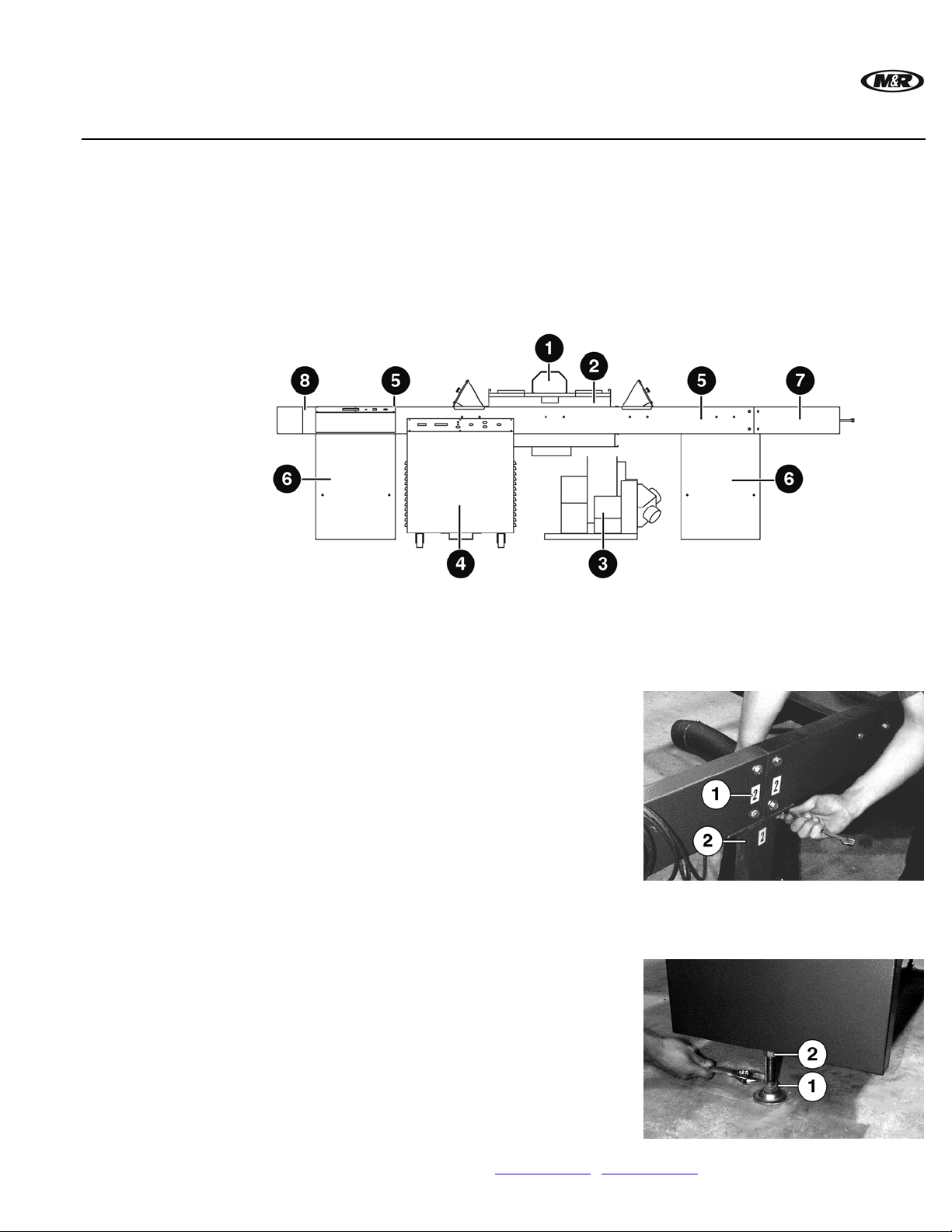
The dryer consists of eight basic components. (See Figure 1) Lamp/Reflector Assembly (1),
Vacuum Plenum (2), Vacuum/Exhaust Assembly (3), Power Cabinet (4), Support Rails (5), Su pport
Legs (6), Infeed Conveyor (7) and Outfeed Conveyor (8).
Hardware and
Tools
Step 1
Step 2
Figure 1
Included is the required assembly hardware. Package consists of: 3/8” hex head bolts, washers, lock
washers and nuts. Additional tools required: 1/2”, 9/16”, 3/4” and 15/16” Combination Wrenches,
5/16” Hex Wrench and Level.
Place the conveyor sections in the area where the dryer
will be used. Numbers (1) are attached to the sides of all
sections of the conveyor assembly. Match the numbers to
assemble the equipment.
For example, the infeed section of the conveyor is marked
with reference number 2. Assemble the support rails, using
the 3/8” - 16 hex bolts, washers, lock washers and hex
nuts, with the conveyor and support leg (2). The numbers
are designed so that they may be removed at the
completion of the assembly.
Do not tighten the bolts for the support legs at this time.
The dryer must be leveled before tightening these bolts.
Level dryer along the conveyor length and across the UV
assembly. Use adjusting pads (1) to level. After leveling,
tighten the locknut (2).
After leveling, tighten all leg bolts.
M&R Companies 1N 372 Main St. Glen Ellyn, IL 60137 USA 15
Tel: +630-858-6101 Fax: +630-858-6134 www.mrprint.com | store.mrprint.com
Page 16
Step 3
Vitran II
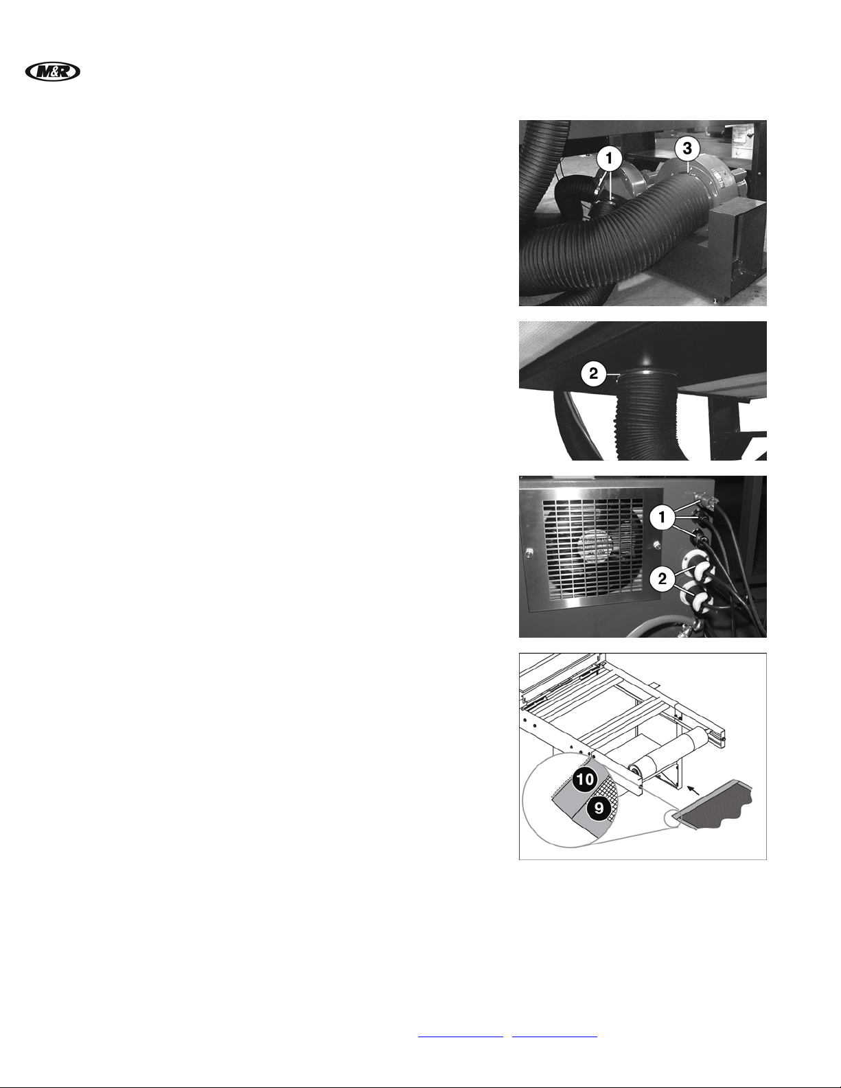
Position the Vacuum/Exhaust Assembly under the Vacuum
Plenum.
Note: Position the Vacuum/Exhaust Assembly on the side of the
conveyor opposite the control panel to allow for the
attachment of the exhaust ducting by your
Heating/Ventilation Contractor.
Two 5” diameter and one 10” diameter flexible duct hoses
are supplied with the dryer. Using the hose clamps
provided, attach one 5” hose on each side of the
lamp/reflector housing assembly. The other ends of these
hoses attach to the dual hose duct assembly (1) on the
Vacuum/Exhaust Assembly. The larger 10” hose is
attached to the opening on the underside of the conveyor
below the vacuum plenum (2). Using the hose clamp
provided, attach the other end of the 10” hose to the
exhaust blower port on the Vacuum/Exhaust Assembly (3).
™
V.112910
Step 4
Step 5 Installing the Conveyor Belt
Position the Power Cabinet on the same side of the
conveyor as the conveyor control panel. Plug in the three
power cords from the conveyor controls into the outlets (1).
Plug in the two power cords from the Vacuum/Exhaust
Assembly to the outlets (2).
Before installing belt, remove specification tag from belt
flap and place it on the inside cover of this manual for
future reference.
From the bottom of the infeed side of the dryer, feed the
belt (9), zipper (10) down, through the Vacuum Plenum
until it exits the outfeed end.
16 M&R Companies 1N 372 Main St. Glen Ellyn, IL 60137 USA
Tel: +630-858-6101 Fax: +630-858-6134 www.mrprint.com | store.mrprint.com
Page 17
V.112910 Vitran II™
Step 5a
Step 5b
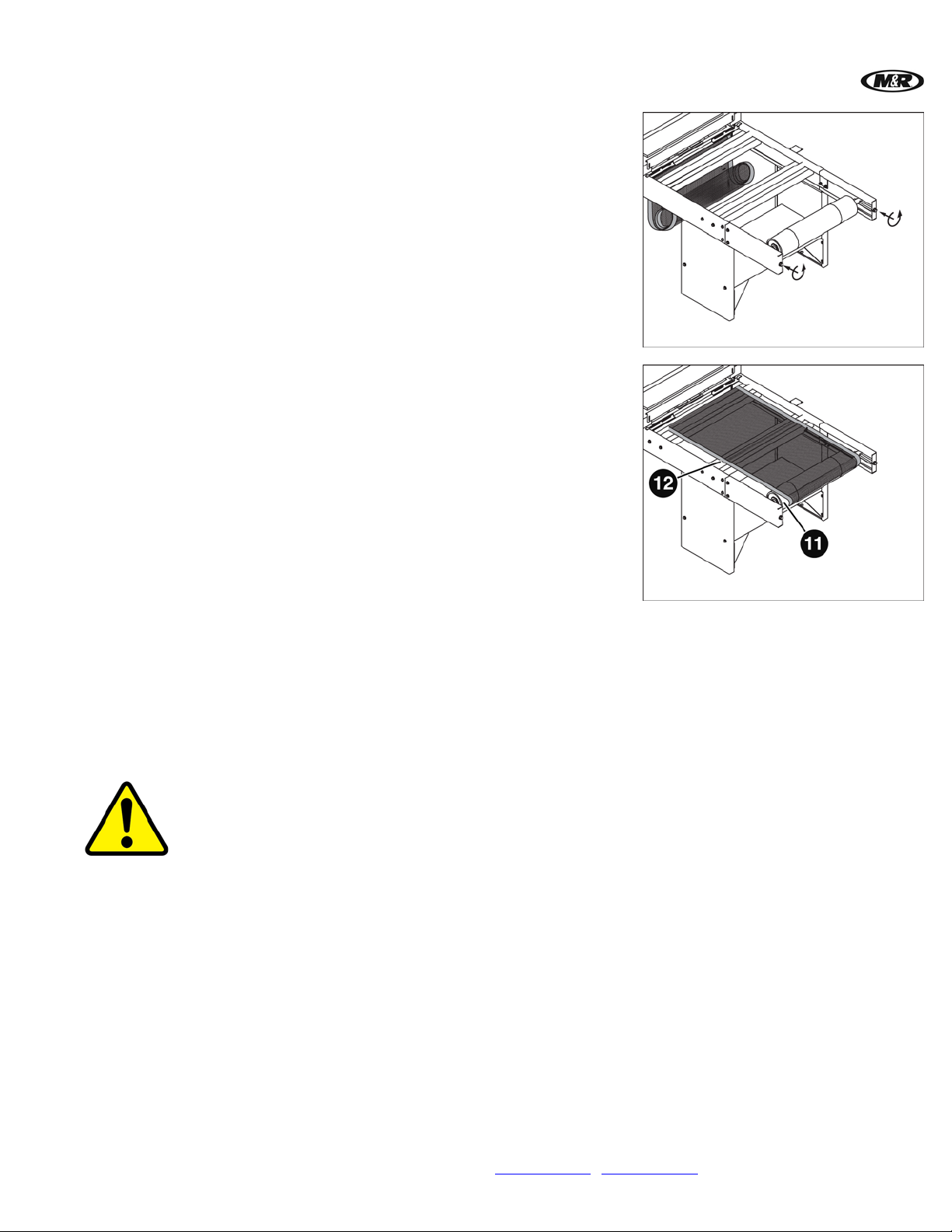
To complete installation of the Conveyor Belt, use a 3/4”
wrench to move the infeed roller all the way in by turning
the adjustment bolts counterclockwise.
Note: Do not adjust the Outfeed Roller.
Pull the Conveyor Belt out and around the Infeed Roller
(11), and then place it flat across the top of the Support
Rails (12). Feed the remainder of the belt through the
Vacuum Plenum and bring the two ends together.
Step 5c
Step 6
Remove metal pin from one end of the metal lacing. Connect both ends of Conveyor Belt by aligning
the metal lacing and re-inserting metal pin.
Conveyor Belt Tensioning
Tension the belt by turning both Infeed Roller adjustment bolts an even number of turns clockwise,
until the belt starts to move. Next, place enough product on the belt to simulate production. Run the
belt and make sure the belt does not slip. If the belt slips, turn both Infeed Roller adjustment bolts
evenly in 1/2 turn increments until the belt starts to move again.
WARNING: Do not over-tension the Conveyor Belt. Over-tensioning puts unnecessary strain on the
Conveyor Drive Motor and shortens Conveyor Belt life. DAMAGE TO THE BELT DUE TO OVER-
TENSIONING IS NOT COVERED BY YOUR WARRANTY!
Conveyor Belt Tracking
IMPORTANT: Do not adjust the Outfeed Roller.
The infeed and outfeed rollers use a “crowned” design, meaning that the roller is thicker in the middle
than it is on the ends. When properly tensioned, this helps the Conveyor Belt track more efficiently.
Use a 3/4” wrench on the Infeed Roller to adjust tracking. Do not adjust the bolts more than 1/2 turn
at a time, and test belt tracking after every adjustment.
Note: To see tracking results faster, set the conveyor speed to its maximum setting.
Turn the left tension bolt counterclockwise if the belt is tracking to the right.
Turn the right tension bolt counterclockwise if the belt is tracking to the left.
M&R Companies 1N 372 Main St. Glen Ellyn, IL 60137 USA 17
Tel: +630-858-6101 Fax: +630-858-6134 www.mrprint.com | store.mrprint.com
Page 18
Vitran II
Adjusting Belt
Speed
4.1.1 UV Lamp Installation and Replacement
™
V.112910
IMPORTANT: Upon the initial start up of the dryer you will notice the elasticity of the Conveyor Belt
will change in reaction to exposure in the UV Chamber. This is a normal condition. For belt tracking,
allow a minimum of four hours running time with both heat and cool down cycles for proper
adjustments. This practice allows a new belt to compensate for expansion during initial adjustment
and dryer operation. Monitor the belt for the first 30 days of operation and make adjustments, as
outlined above, when necessary.
Initial recommended belt speed is 15’ (4.57M) per minute. After starting your dryer, adjust belt speed
accordingly.
WARNING: To prevent possible injury to personnel and/or damage to the equipment, lock
out and tag the electrical service to the equipment.
Step 1
Step 2
WARNING: Oily or foreign substances will damage the lamp. In case of contact, wipe the
glass surface with Isopropyl Alcohol. Always wear lint-free gloves when handling the lamp.
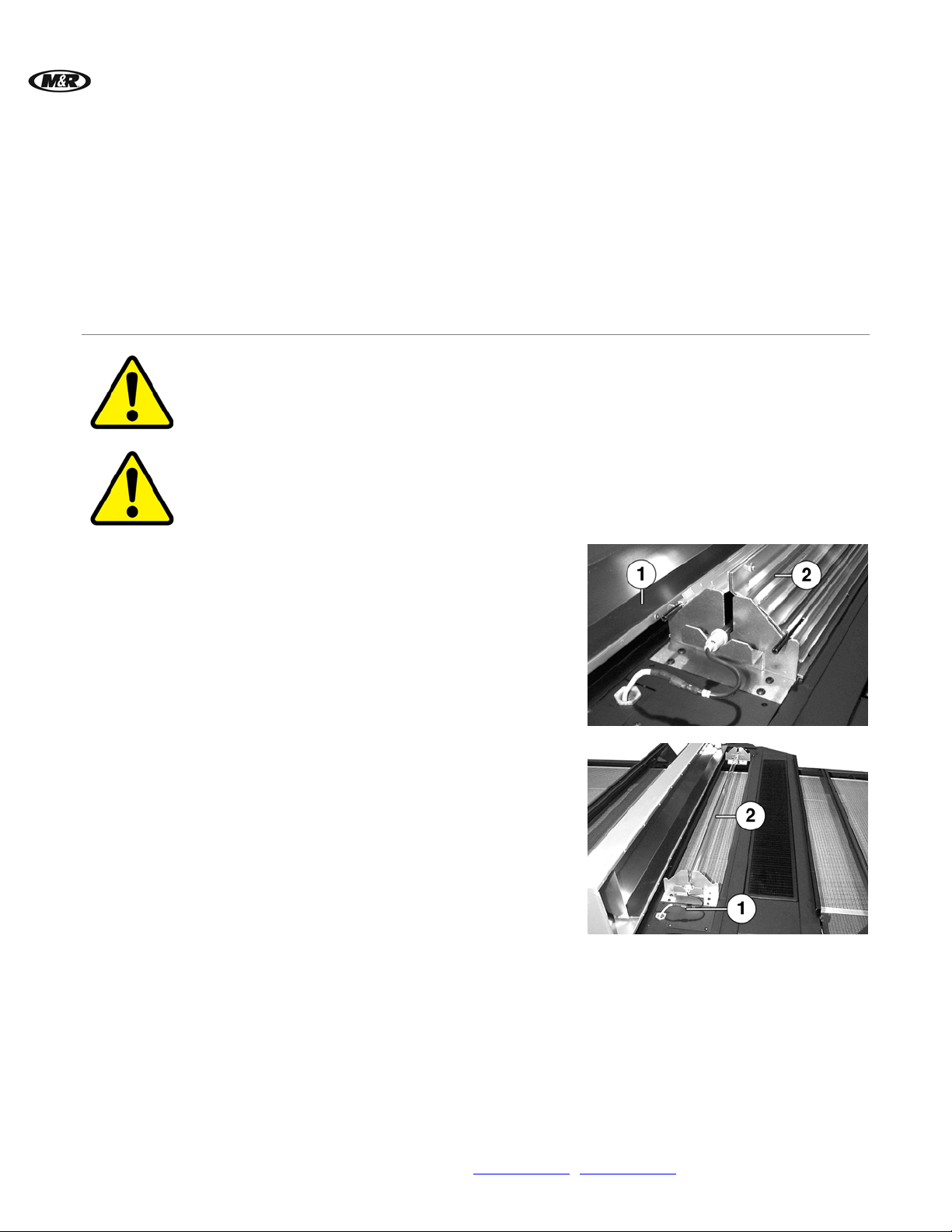
Rotate reflector housing (1) up and remove
reflector assembly (2).
Disconnect wires (1) from both ends of the UV
lamp and wearing lint-free gloves, carefully
remove the Lamp (2).
Step 3
Install replacement lamp and reverse the above steps to reassemble the Reflector Housing.
4.2 Installation
Exhaust Ducts
18 M&R Companies 1N 372 Main St. Glen Ellyn, IL 60137 USA
Tel: +630-858-6101 Fax: +630-858-6134 www.mrprint.com | store.mrprint.com
IMPORTANT:
and heated air that are a natural by-product of the UV lamp.
Contractor to be sure that exhaust ducts will meet local building/fire codes and regulations before
installation. M&R Printing Equipment does not specify or recommend materials for the exhaust
ducting of this equipment.
This equipment requires the installation of exhaust ducting for the removal of ozone
Check with your local heating/ventilation
Page 19
V.112910 Vitran II™
5. Operation
5.1 Dryer Control Panel
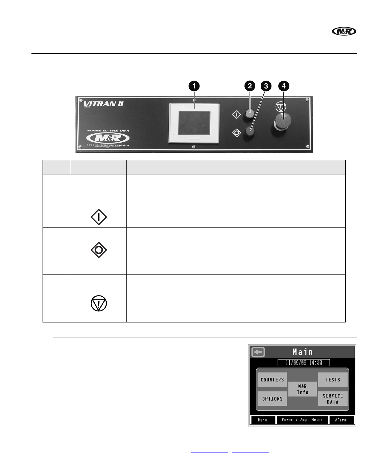
Number Name Function
1
2
3
4
5.1.1 Operator Interface
Operator
Interface
Operator
Interface
START Button
STOP Button
EMERGENCY
STOP Button
The Operator Interface is used to access and
adjust all functions of the press. When electrical
power is turned on, the message screen displays
the MAIN menu. The available menu selections
are COUNTERS, OPTIONS, M&R Info, TESTS
and SERVICE DATA.
Displayed along the bottom of the screen are
Main, Power/Amp Meter and Alarm.
The current month, date, year and time is
displayed at the top of the MAIN screen.
Used to display information regarding operational, programming, and system
status messages.
The green START button supplies electrical power to the control system. The
button lights up when pressed, confirming that electrical power is on.
The red STOP button turns off electrical power to the UV Station. The button
illuminates when pressed, confirming that electrical power has been
disconnected and the auto shutdown process has started.
Note: The UV Cooling Fans continue to run until the UV Station reaches 150 degrees F
(65 degrees C). Then the Cooling Fans shut down and the red STOP button light
goes out.
The red EMERGENCY STOP button shuts down the UV lamps and stops all
operation.
Press the button in until it remains depressed to activate.
Turn the button clockwise until it pops out to deactivate.
Note: Use the EMERGENCY STOP button only in emergency situations.
M&R Companies 1N 372 Main St. Glen Ellyn, IL 60137 USA 19
Tel: +630-858-6101 Fax: +630-858-6134 www.mrprint.com | store.mrprint.com
Page 20
™
Vitran II
M&R Info
Power/Amp.
Meter
V.112910
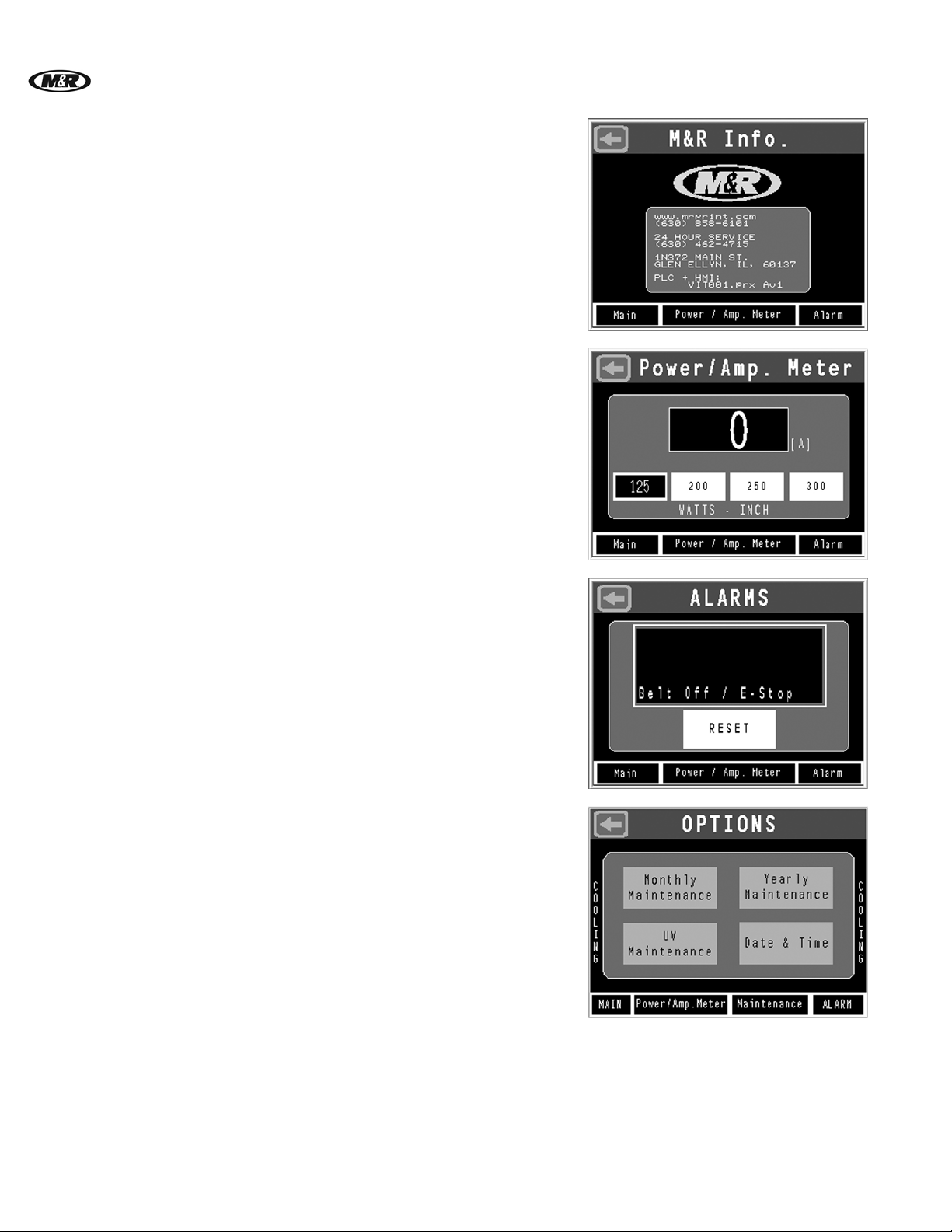
Press the M&R INFO button on the MAIN screen.
The M&R INFO screen contains information on
how to contact M&R Printing Equipment and
program information.
Press the Arrow Left button to return to the MAIN
screen.
Press Power/Amp. Meter at the bottom of the
Main screen. Select the power output setting from
the Power/Amp. Meter screen.
IMPORTANT: Avoid unnecessary on/off cycling of
the UV Lamp. During production breaks, leave the
lamp on and select 125 watts/inch from the
Power/Amp. Meter screen.
Alarm
Setting Date
and Time
Press Alarm at the bottom of the Main screen.
The Alarms menu is used to display the cause of
alarm conditions.
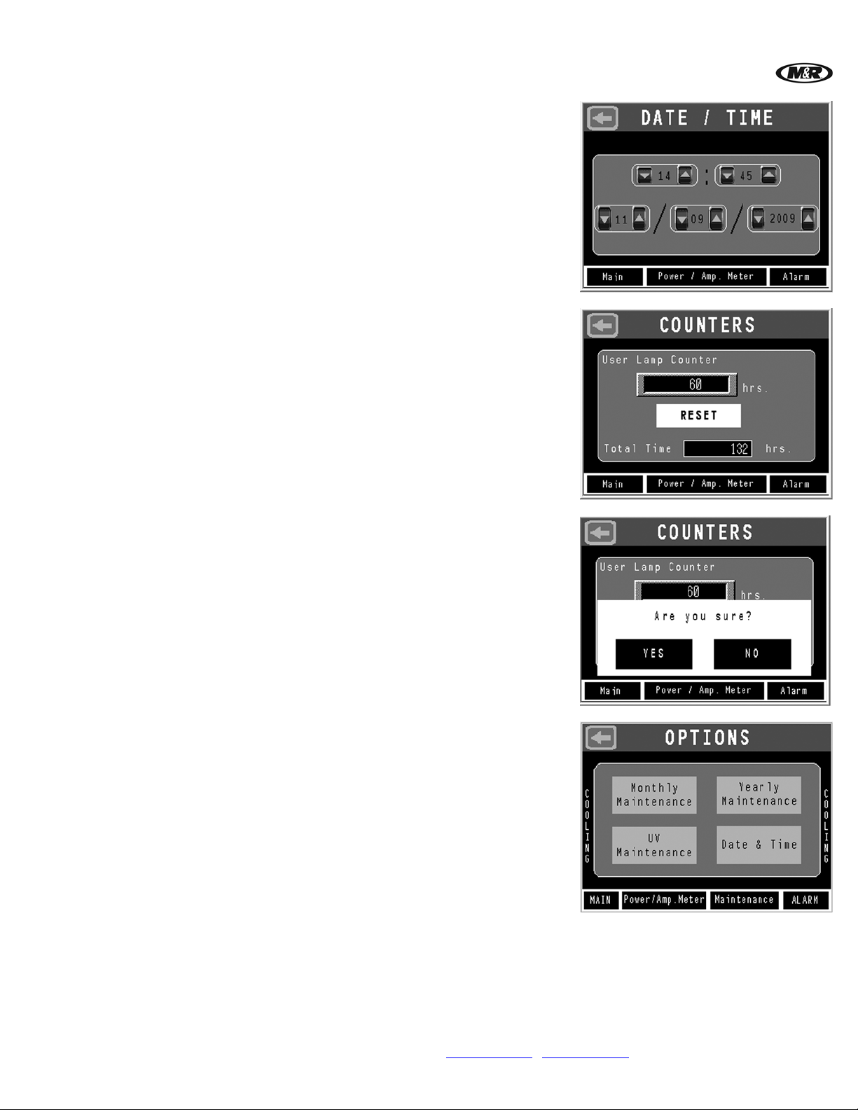
Press OPTIONS on the MAIN screen, then press
Date & Time.
20 M&R Companies 1N 372 Main St. Glen Ellyn, IL 60137 USA
Tel: +630-858-6101 Fax: +630-858-6134 www.mrprint.com | store.mrprint.com
Page 21
V.112910 Vitran II™
To set the time of day, use the Arrow Up/Down
buttons located on the left (Decrease) and right
(Increase) of each number. The time of day is
displayed using a 24 hour clock where 13:00
represents 1:00 PM.
To change the date, use the Arrow Up/Down
buttons located at the left (Decrease) and right
(Increase) of each number indication representing
the month, date and year.
Counters
Press COUNTERS on the MAIN screen.
COUNTERS show User Lamp Counter in hours.
Press RESET button to reset.
Press YES to reset User Lamp Counter.
Options
Press OPTIONS on the MAIN screen. The
OPTIONS menu is used to access the
Maintenance screens and the Date & Time
screen. Press Monthly, Yearly and UV
Maintenance buttons to view maintenance
requirements.
M&R Companies 1N 372 Main St. Glen Ellyn, IL 60137 USA 21
Tel: +630-858-6101 Fax: +630-858-6134 www.mrprint.com | store.mrprint.com
Page 22
™
Vitran II
UV
Maintenance
Monthly
Maintenance
V.112910
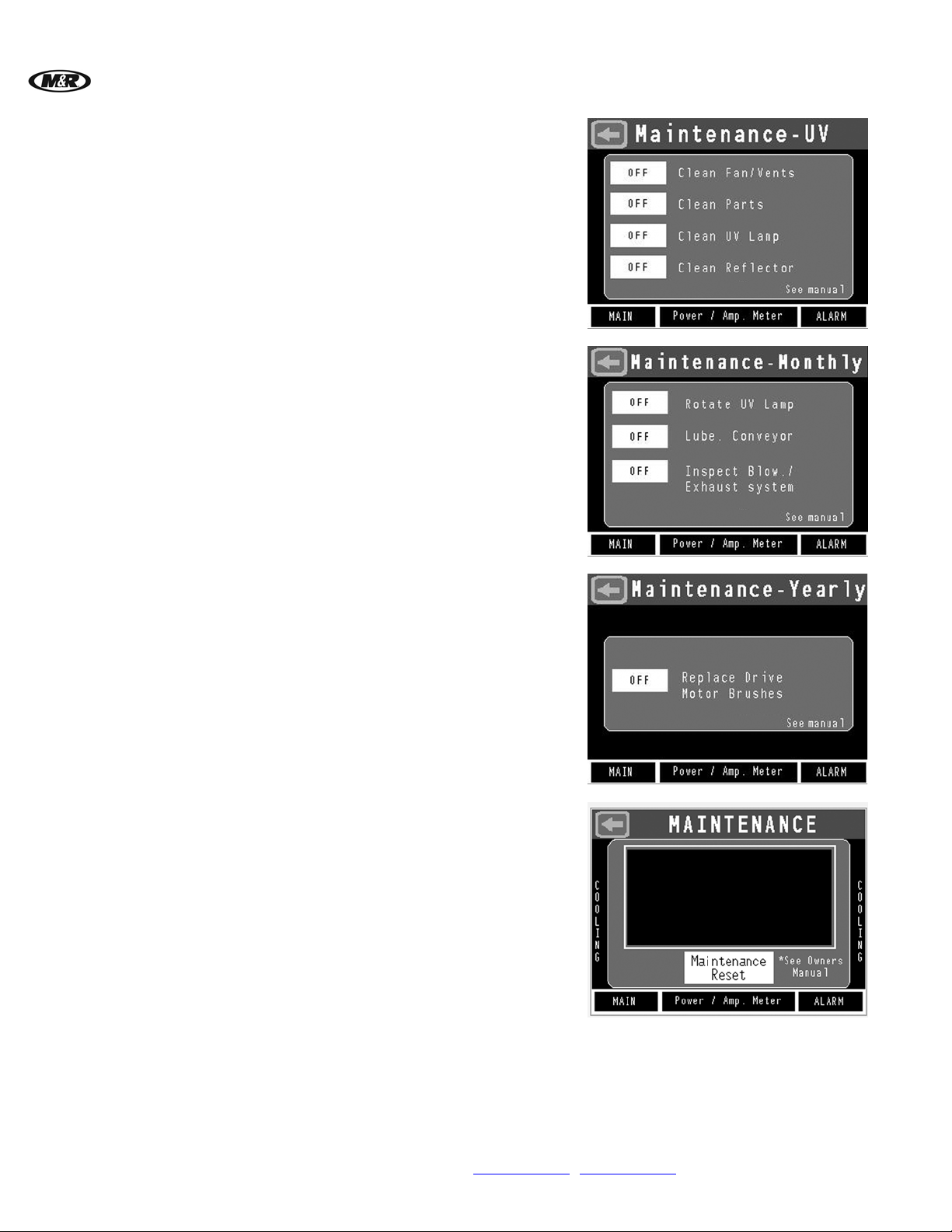
This screen displays Weekly UV Maintenance
requirements. Refer to the Scheduled
Maintenance Section of this manual for detailed
maintenance information.
When ON is selected, a message appears on the
bottom of the screen when maintenance is
required. If OFF is selected, messages will not
appear.
This screen displays Monthly Maintenance
requirements. Refer to the Scheduled
Maintenance Section of this manual for detailed
maintenance information.
When ON is selected, a message appears on the
bottom of the screen when maintenance is
required. If OFF is selected, messages will not
appear.
Yearly
Maintenance
This screen displays Yearly Maintenance
requirements. Refer to the Scheduled
Maintenance Section of this manual for detailed
maintenance information.
When ON is selected, a message appears on the
bottom of the screen when maintenance is
required. If OFF is selected, messages will not
appear.
If periodic maintenance reminders are selected to
ON, when maintenance is due, Maintenance
appears on the bottom of the MAIN screen.
Timers are based on eight hours per day of
machine usage.
Press Maintenance Reset to reset maintenance
timers.
22 M&R Companies 1N 372 Main St. Glen Ellyn, IL 60137 USA
Tel: +630-858-6101 Fax: +630-858-6134 www.mrprint.com | store.mrprint.com
Page 23
V.112910 Vitran II™
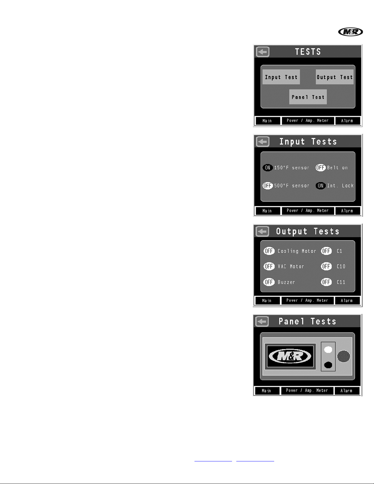
Tests
Press TESTS on the MAIN screen to access the
TESTS screen. Input Tests, Output Tests and
Panel Tests are displayed.
Input Tests checks the function of devices used
in the control system. Buttons change color and
change from ON to OFF when the input device is
actuated.
Output Tests checks the function of devices used
in the control system. Buttons change color and
change from ON to OFF when the output device is
actuated.
Panel Tests checks the function of the switches
on the control panel.
To test the Emergency Stop button, press the red
button to activate it. When deactivated the
indication for the Emergency Stop button in the
TEST screen appears red in color. When
activated, the indication will change to a gray
color. Other buttons on the operator panel are
tested in the same manner.
M&R Companies 1N 372 Main St. Glen Ellyn, IL 60137 USA 23
Tel: +630-858-6101 Fax: +630-858-6134 www.mrprint.com | store.mrprint.com
Page 24
™
Vitran II
Service Data
V.112910
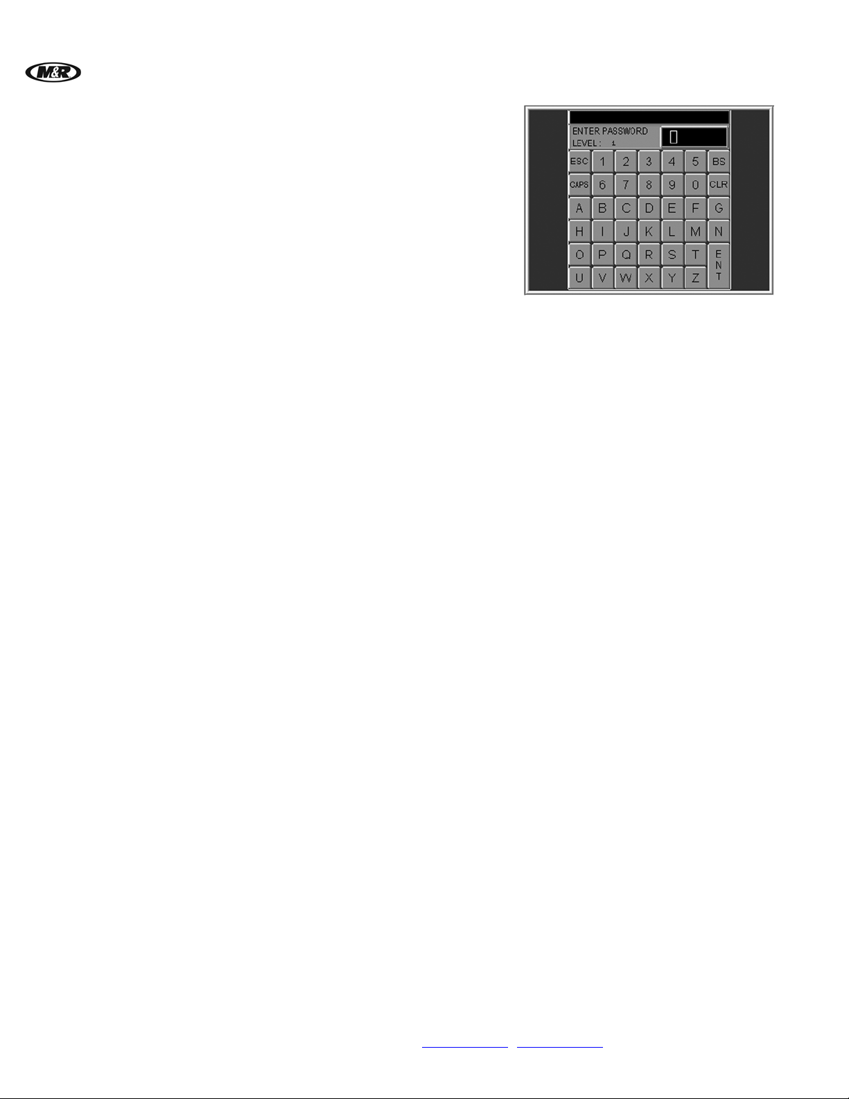
Press SERVICE DATA on the MAIN screen. The
SERVICE DATA screen is intended for use by
M&R Authorized Service Personnel only and
requires the use of a password for access.
Do not attempt to access the SERVICE DATA
menu!
24 M&R Companies 1N 372 Main St. Glen Ellyn, IL 60137 USA
Tel: +630-858-6101 Fax: +630-858-6134 www.mrprint.com | store.mrprint.com
Page 25
V.112910 Vitran II™
5.2 Conveyor Control Panel
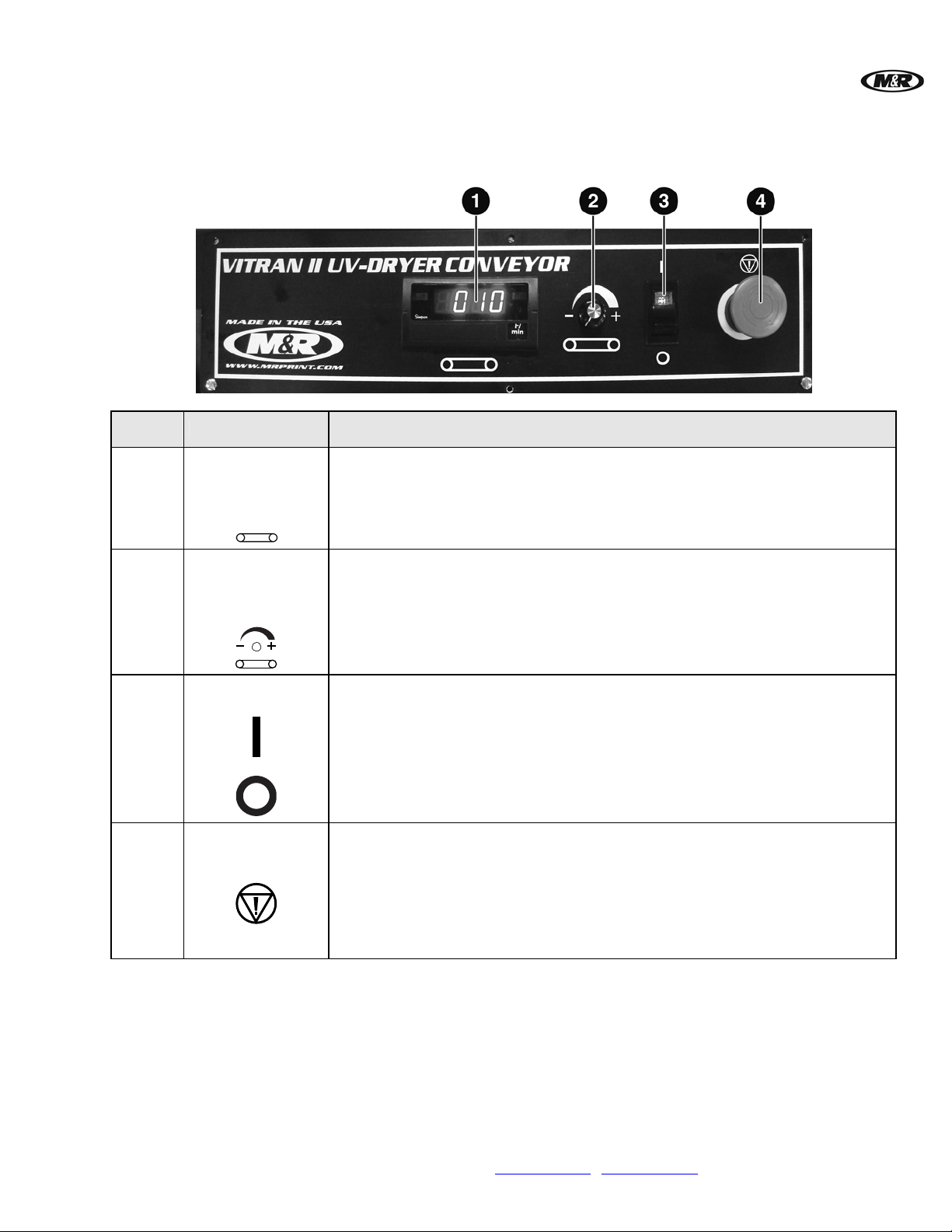
Number Name Function
1
CONVEYOR
SPEED
The digital CONVEYOR SPEED INDICATOR displays the current conveyor belt
speed in feet per minute.
INDICATOR
2
CONVEYOR
SPEED CONTROL
Knob
The CONVEYOR SPEED CONTROL knob controls conveyor belt speed.
Turn the knob clockwise to increase speed.
Turn the knob counterclockwise to decrease speed.
3
ON/OFF Switch
The ON/OFF switch supplies electrical power to the conveyor.
4
EMERGENCY
STOP Button
The red EMERGENCY STOP button shuts down the UV lamps and stops all
dryer operation.
Press the button in until it remains depressed to activate.
Turn the button clockwise until it pops out to deactivate.
Note: Use the EMERGENCY STOP button only in emergency situations.
M&R Companies 1N 372 Main St. Glen Ellyn, IL 60137 USA 25
Tel: +630-858-6101 Fax: +630-858-6134 www.mrprint.com | store.mrprint.com
Page 26

™
Vitran II
V.112910
5.3 Principles of UV Curing
Operating
Principles
Curing Stations
Power Level
The UV (Ultraviolet) curing stations consist of a single or multiple reflector and reflector
housing, power component cabinet/control panel, mercury vapor lamp and cooling/venting
system. The standard mercury vapor lamp generates three distinct forms of energy:
ultraviolet, infrared (heat), and intense (visible) light. The curing system works by controlled
exposure of the monomers and sensitizers in the ink to the ultraviolet energy produced by
the mercury vapor lamp. This process, known as polymerization, cross links the monomers
and results in “instant” curing, leaving the substrate immediately available for further
processing. The UV curing stations are designed to maximize the effects of the ultraviolet
energy while minimizing infrared energy and protecting the operator from the potentially
harmful effects of direct eye or skin contact with UV radiation.
The UV curing stations incorporate a unique air-cooled system to minimize the effects of the
infrared energy (heat) generated by the mercury vapor lamp. The system consists of the
following components:
1. A vacuum turbine draws ambient (room temperature) air through the entry and exit
sections of the UV curing module, and through circular grates located on top of the
reflector housing. Due to the reflectors unique inner sleeve design, this ambient air can
reach the reflector without exposing the operator to stray UV light rays. At the same
time, the vacuum turbine draws heated air from under the reflector through a narrow
channel at the top of the reflector. This heated air is then exhausted through the two
flexible hoses attached at both ends of the reflector housing.
2. A patented (U.S. Patent No. 5,216,820) reflector is designed to reflect energy around
the UV lamp rather than back onto it. This results in lower operating temperatures and
extends the life of the UV lamp.
Note: Because the UV system cools the substrate by directing cooling air across the sheet, not down
onto it, problems with the substrate shifting or fluttering while under the lamp housing are
minimized.
The proper power level setting (watts per inch) is determine d by several factors and will
require some trials before optimum curing results are achieved. The conveyor speed should
be run as fast as possible to achieve proper cure and adhesion. Lower speeds may result in
over-curing, causing inter-coat adhesion problems. There are several factors to consider
when determining speed and lamp power level settings:
1. Type and viscosity of the ink: A mercury vapor lamp emits a range of UV energy that
is appropriate for most UV applications. However, different ink characteristics, such as
pigments and resins, will affect the specific curing rate. Heavier ink deposits, more
opaque films and some metal and glass substrates generally require greater exposure
to UV energy.
2.
Lamp position: The UV Stations feature adjustable lamp height that can be adjusted to
accommodate various substrate types and thicknesses.
3. Lamp Life: As the lamp ages it may draw less current, which indicates the approaching
need for replacement. Decreasing the conveyor speed may be necessary at this point to
insure proper cure.
26 M&R Companies 1N 372 Main St. Glen Ellyn, IL 60137 USA
Tel: +630-858-6101 Fax: +630-858-6134 www.mrprint.com | store.mrprint.com
Page 27
V.112910 Vitran II™
5.4 Operation Overview
5.4.1 Lamp Focus
Unfocused
Setting
Focused
Setting
The lamp is closer to the reflector. This generates
wider, less aggressive band of UV energy and
also generates more infrared energy for less heatsensitive substrates such as heavy styrene, metal,
glass and polystyrene. The unfocused setting can
be advantageous for ink and substrates which
require heat to “set up” the curing process.
The lamp is moved down away from the reflector
and closer to the conveyor belt surface. This
setting generates a more highly concentrated
band of UV energy and generates less infrared
energy. It is recommended for heat-sensitive
substrates.
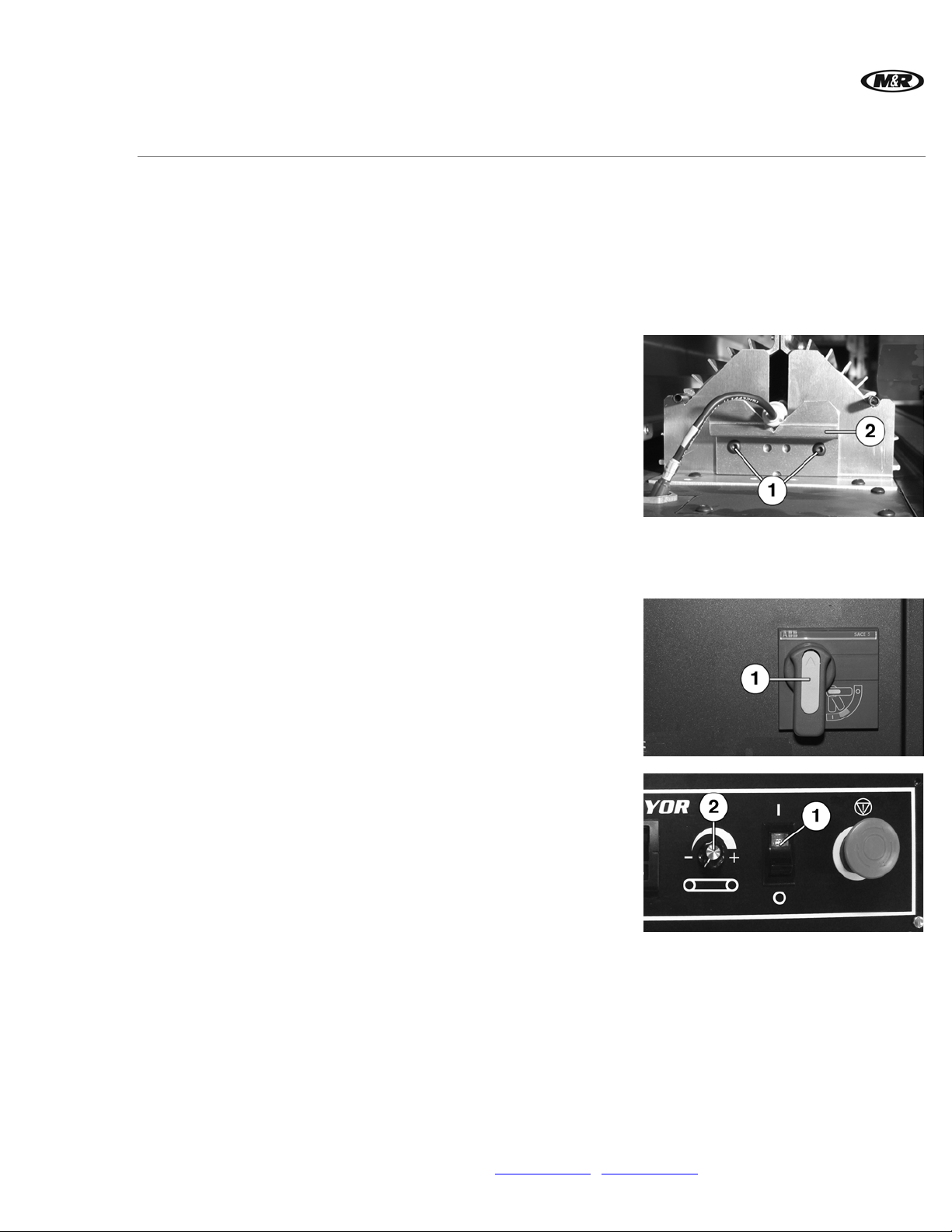
To adjust:
Use a hex wrench to loosen the screws (1) and
then slide the lamp cradle (2) all the way up
(unfocused), or all the way down (focused).
Tighten screws (1). Repeat for other side of lamp
assembly.
5.5 Dryer Startup/Shutdown
Step 1 Dryer Startup
Turn the Main Disconnect Switch (1) to the ON position. An
alarm sounds. Press the ALARM OFF button on the
control panel to silence the alarm.
Step 2
M&R Companies 1N 372 Main St. Glen Ellyn, IL 60137 USA 27
Tel: +630-858-6101 Fax: +630-858-6134 www.mrprint.com | store.mrprint.com
Place the ON/OFF switch (1) on Conveyor control panel in
the ON position. Conveyor belt starts operation.
Turn the CONVEYOR SPEED CONTROL knob (2) to your
required speed setting.
Page 28
Step 3
Step 4
Vitran II
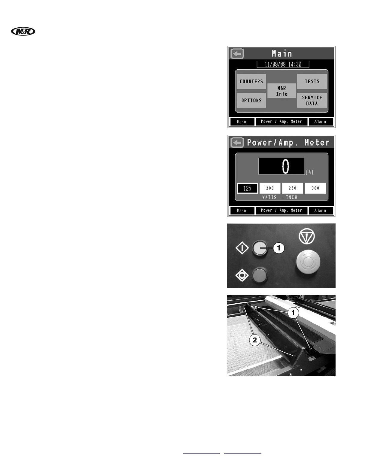
Press Power/Amp. Meter at the bottom of the Main
screen. Select a power output setting from the
Power/Amp. Meter screen.
Push the START button (1) to turn on the dryer exhaust
and cooling blowers. The UV lamps begin their warm up
cycle.
Note: After pressing the START button, the UV Power Output
automatically goes to maximum watts per inch to bring the
lamp up to full power. When the temperature is reached,
the unit automatically adjusts to the setting on the
Power/Amp. Meter screen.
Loosen the left and right lock knobs (1) for the Delivery
Doors on each end of the dryer. Position both doors so that
substrate can enter and exit without interference. Tighten
lock knobs (1) to hold doors in place. Repeat procedure for
Shields (2).
™
V.112910
28 M&R Companies 1N 372 Main St. Glen Ellyn, IL 60137 USA
Tel: +630-858-6101 Fax: +630-858-6134 www.mrprint.com | store.mrprint.com
Page 29
V.112910 Vitran II™
Step 5 Dryer Shutdown
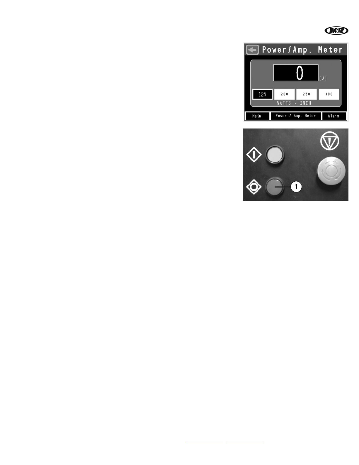
IMPORTANT: Avoid unnecessary on/off cycling of the UV
Lamp. During production breaks, leave the lamp on and
select 125 watts/inch from the Power/Amp. Meter screen.
Press the STOP button (1) to turn off electrical power to the
control system. The button illuminates when pressed,
confirming that electrical power has been disconnected and
dryer shutdown has started. The Exhaust Blower and
Conveyor Drive Motor continue to run until the interior of
the Lamp/Reflector Housing reaches 150 degrees F (65
degrees C).
Then the Blower shuts down and the red
STOP button light goes out.
M&R Companies 1N 372 Main St. Glen Ellyn, IL 60137 USA 29
Tel: +630-858-6101 Fax: +630-858-6134 www.mrprint.com | store.mrprint.com
Page 30
™
Vitran II
V.112910
6. Scheduled Maintenance
Benefits
Preparation
Frequency Maintenance
Weekly
Properly maintained equipment operates more efficiently, reduces operating costs, and lasts longer.
A properly managed preventive maintenance program can minimize downtime.
An effective preventive maintenance program includes:
• proper selection, handli ng, and application of lubricants
• stocking high-quality replacement parts
• general cleaning and appearance of equipment
• creation of a preventive maintenance history for each piece of equipment
Preventive maintenance documentation can be an invaluable resource.
WARNING: To prevent possible injury to personnel and/or damage to the equipment, lock out and tag the
electrical service to the equipment.
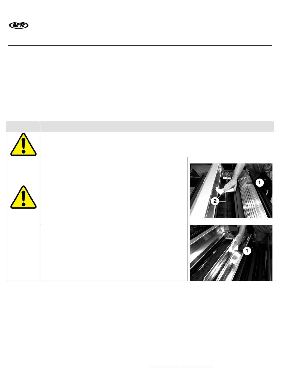
Clean UV Lamp
Items required:
1 - Isopropyl Alcohol
1 - Lint-Free Cloth
WARNING: Oily or foreign substances will damage the lamp. In
case of contact, wipe the glass surface with Isopropyl Alcohol.
Always wear lint-free gloves when handling the lamp.
1. Remove reflector (1).
2. Clean lamp (2) using Isopropyl Alcohol on a lint-free cloth.
Clean Reflector
Items required:
1 - Isopropyl Alcohol
1 - Lint-Free Cloth
1. Remove reflector (1).
2. Clean reflector (1) using Isopropyl Alcohol on a lint-free cloth.
30 M&R Companies 1N 372 Main St. Glen Ellyn, IL 60137 USA
Tel: +630-858-6101 Fax: +630-858-6134 www.mrprint.com | store.mrprint.com
Page 31
V.112910 Vitran II™
Frequency Maintenance
Weekly
Cont.)
(
Monthly
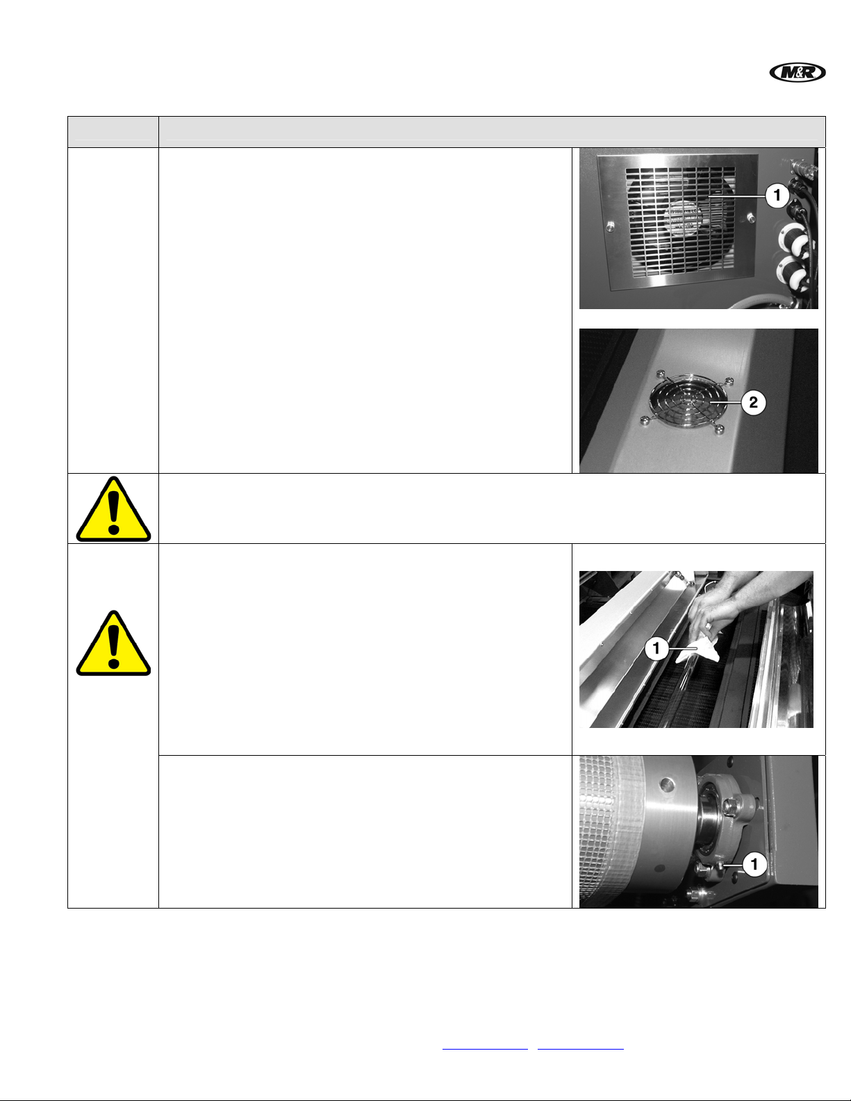
Clean Ventilation Fan and Air Vents
Items required:
1 - Vacuum
Use a vacuum to clean the ventilation fan and finger guard
assembly on power control cabinet (1) and lamp housing (2).
WARNING: To prevent possible injury to personnel and/or damage to the equipment, lock out and tag the
electrical service to the equipment.
Rotate UV Lamp
Items required:
1 - Lint-Free Cloth
WARNING: Oily or foreign substances will damage the lamp. In
case of contact, wipe the glass surface with Isopropyl Alcohol.
Always wear lint-free gloves when handling the lamp.
1. After 250 hours of use, the lamp should be rotated 90
degrees. As the lamp ages, the material inside the lamp
plates the quartz envelope.
2. Using a lint-free cloth (1), rotate lamp 90 degrees.
Lubricate Conveyor Roller Bearings
Items required:
1 - High Temperature Grease (M&R Part No. 7018004)
1 - Standard pump action grease gun
Use high temperature grease at the conveyor outfeed. There is
a grease fitting (1) at each end of the roller.
M&R Companies 1N 372 Main St. Glen Ellyn, IL 60137 USA 31
Tel: +630-858-6101 Fax: +630-858-6134 www.mrprint.com | store.mrprint.com
Page 32
™
Vitran II
Frequency Maintenance
V.112910
Monthly
(Cont.)
Clean and Inspect Blower
Items required:
1 – Vacuum
1 – 5/16” Nut Driver
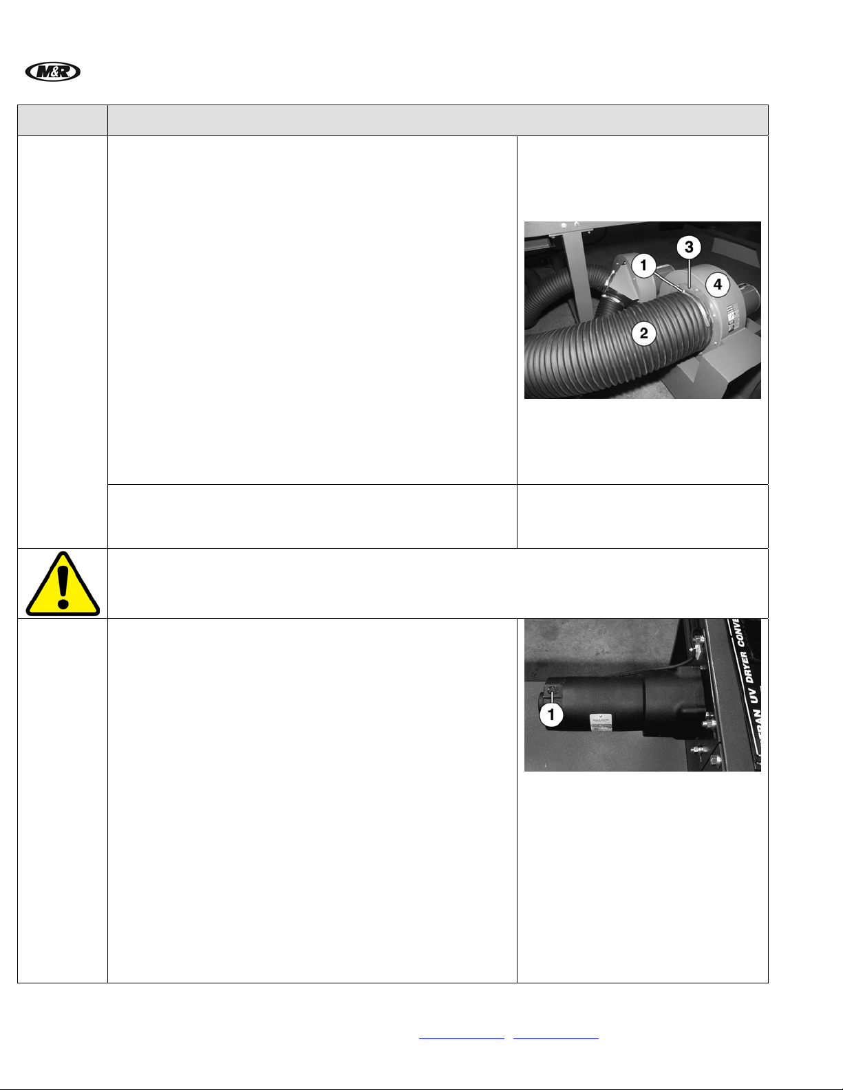
1. Loosen the hose clamp (1) and remove the flexible duct (2).
2. Remove blower flange assembly (3) and move to the side.
3. Use a vacuum to remove any lint from blower squirrel cage
wheel (4). (Not Visible)
4. Use a vacuum to remove any lint from the flexible duct.
Inspect for damage and replace if necessary.
5. Reassemble blower flange assembly (3).
6. Reassemble flexible duct (2) and hose clamp (1). Tighten
securely.
Repeat for other blower.
Check Exhaust System
Check exhaust system to make sure ozone is properly vented
and that the cooling and vacuum system is operating properly.
WARNING: To prevent possible injury to personnel and/or damage to the equipment, lock out and tag the
electrical service to the equipment.
Yearly Replace Conveyor Drive Motor Brushes
Items required:
1 – Drive Motor Brushes
1. Loosen the Conveyor Belt at the Infeed end of the conveyor.
2. Pull the Conveyor Belt through the UV chamber until the
connecting seam is above the Conveyor Drive Motor.
3. Remove the metal pin from the metal lacing to disconnect
the Conveyor Belt.
4. Remove the dust caps (1) over each brush (2 per motor).
5. Remove old motor brush and replace with new brush.
6. Replace the dust caps.
7. Reconnect Conveyor Belt.
8. Adjust the belt tensioning and tracking.
32 M&R Companies 1N 372 Main St. Glen Ellyn, IL 60137 USA
Tel: +630-858-6101 Fax: +630-858-6134 www.mrprint.com | store.mrprint.com
Page 33

V.112910 Vitran II™
Frequency Maintenance
Yearly
(Cont.)
Replace UV Lamp
Items required:
1 – UV Lamp
Replace UV lamp after 1000 hours of operation. Refer to UV Lamp Installation and Replacement in this
manual.
M&R Companies 1N 372 Main St. Glen Ellyn, IL 60137 USA 33
Tel: +630-858-6101 Fax: +630-858-6134 www.mrprint.com | store.mrprint.com
Page 34
™
Vitran II
V.112910
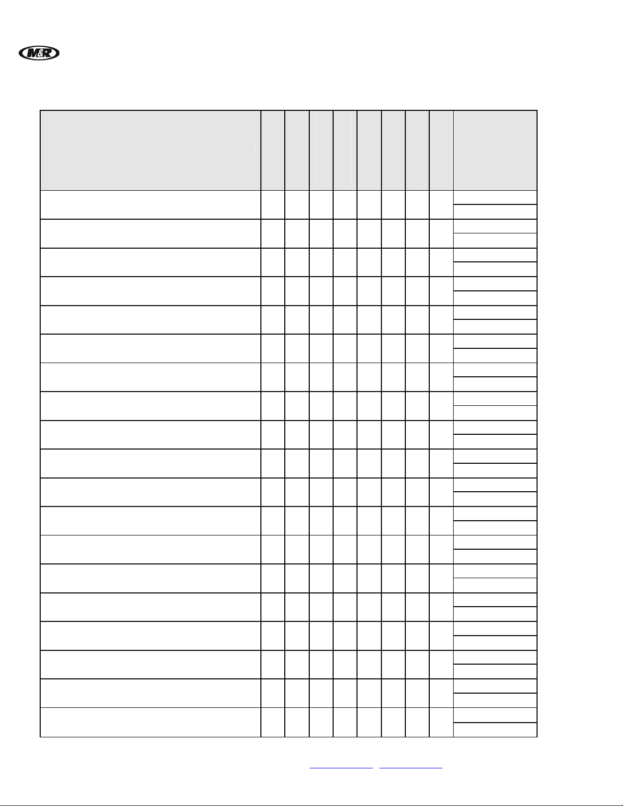
6.1 Scheduled Maintenance Log
Maintenance Procedure
Clean UV Lamp
Clean Reflector
Clean Ventilation Fan and Air Vents
Rotate UV Lamp
Lubricate Conveyor Roller Bearings
Clean and Inspect Blower
Check Exhaust System
Replace Conveyor Drive Motor Brushes
Replace UV Lamp
Daily
Weekly
X
X
X
X
X
X
X
X
X
Every 2 Weeks
Monthly
Every 3 Months
Every 6 Months
Yearly
Every 3 Years
Date
performed/
Initials
34 M&R Companies 1N 372 Main St. Glen Ellyn, IL 60137 USA
Tel: +630-858-6101 Fax: +630-858-6134 www.mrprint.com | store.mrprint.com
Page 35
V.112910 Vitran II™
7. Troubleshooting
General Guide
Schematic
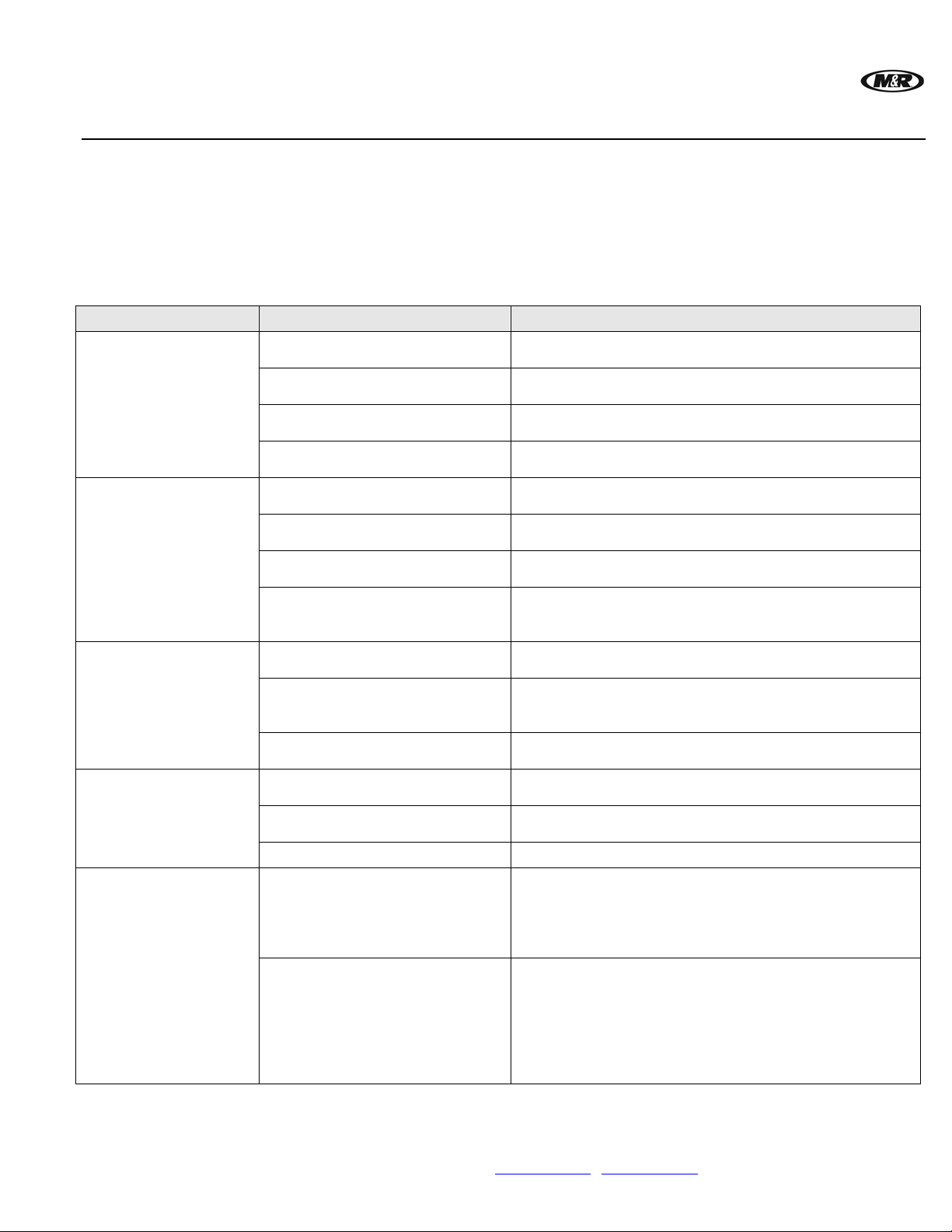
Problem Probable Causes Solution
Image not cured.
The cured image
exhibits poor
intercoat adhesion.
The cured image is
blocking or offsetting
when stacked.
The cured image
indicates poor ink
flow, orange peel, pin
holes.
The cured image
exhibits a “dried in
the screen”
appearance in some
areas of the print.
The following information is provided as a guide for troubleshooting. If you have any questions
regarding the installation, operation, or preventive maintenance procedures for this equipment,
contact The M&R Companies Service Department. Anyone using this troubles hooting guide should
have a working knowledge of electrical power and the control systems an d on this equipment.
Electrical schematics are located in the back of this manual.
UV power output setting is too
low.
The lamp reflector may be
contaminated with dirt or dust.
The ink film deposit is too
thick.
The conveyor speed is too fast.
UV power output setting is too
low.
The lamp reflector may be
contaminated with dirt or dust.
The conveyor speed is too fast.
The color density of the ink
may be too great for proper
cure.
UV power output setting is too
high.
Check the UV lamp for proper
power output.
The conveyor speed is too
slow.
The off-contact adjustment on
the press may be set too high.
Check screen mesh tension, it
may not be tight enough.
Ink viscosity may be too high.
Check the stencil. Is the screen
mesh clear? Are you using the
proper mesh count to achieve
the desired print and curing
results?
Check the room lighting (overhead lighting) in the area of the
screen. Some industrial light
sources emit enough ultraviolet
energy to begin the crosslinking (premature curing) of
the ink while it is in the screen.
Increase the UV power output to a higher watts/inch
setting.
Clean the reflector as outline in the Scheduled
Maintenance section.
Check the mesh count of the screen which may result in
too thick an ink film.
Decrease the conveyor speed to increase exposure
time.
Increase the UV power output to a higher watts/inch
setting.
Clean the reflector as outline in the Scheduled
Maintenance section.
Decrease the conveyor speed to increase exposure
time.
Changed color density of ink.
Decrease the UV power output to a lower watts/inch
setting.
If the lamp is approaching its maximum service life,
replace the lamp. The UV lamp should be replaced after
every 1000 hours of service.
Increase the conveyor speed to decrease exposure time.
Reduce off-contact adjustment slightly.
Retighten screen if necessary.
Changed ink viscosity.
Change screen or mesh count if necessary.
Change lighting if necessary.
M&R Companies 1N 372 Main St. Glen Ellyn, IL 60137 USA 35
Tel: +630-858-6101 Fax: +630-858-6134 www.mrprint.com | store.mrprint.com
Page 36
™
Vitran II
V.112910
8. Replacement Parts
CE vs. UL
Models
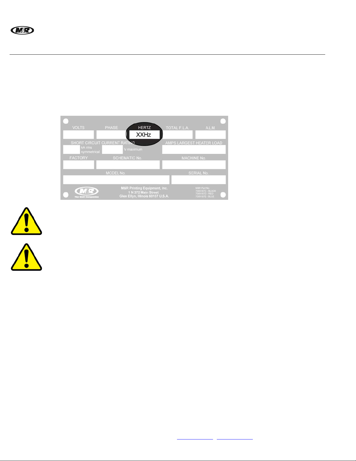
All equipment containing electrical components is designed to comply with either Conformance
European (CE) or Underwriters Laboratories (UL) standards, and each type of equipment has a
different parts list. CE equipment runs at 50 Hz; UL equipment runs at 60 Hz. Electrical
specifications, including Hertz, can be found on the Manufacturer’s Rating Plate similar to the one
shown below.
Note: You must verify whether your equipment is 50 Hz (CE) or 60 Hz (UL) and order parts accordingly.
Schematic
Diagrams for
Electrical Parts
DANGER: Operating this equipment with incorrect electrical parts can result in severe or fata l
personal injuries and/or property damage.
DANGER: The Ballasts (Transformers) used on this equipment, when in operation, outputs high
voltages that may cause serious injury or death. Each Ballast should only be connected or
disconnected by a trained professional.
Each Ballast is part of a “Tuned or Resonant” circuit. If it is a replacement, the circuit in which the
Ballasts operate should be re-tuned to resonance by trained, qualified personnel. This procedure
also requires the proper use of electronic meters which are not part of the machine that this is
installed in.
Also, each Ballast is specially designed for maximum efficiency and longevity, to work in conjunction
with lamps that are properly rated and manufactured to rigid specifications. Use of lamps from other
resources may damage the Ballasts, and/or void the M&R Limited Warranty.
M&R uses the ‘just-in-time’ approach to printing manuals, so the electrical parts and part numbers
shown in this section should be accurate. However, since schematic diagrams are unit-specific, they
remain the most accurate source of electrical part numbers. Cross-reference the part numbers in this
manual with the part numbers in the schematic diagrams in the back of this manual before placing an
order.
36 M&R Companies 1N 372 Main St. Glen Ellyn, IL 60137 USA
Tel: +630-858-6101 Fax: +630-858-6134 www.mrprint.com | store.mrprint.com
Page 37
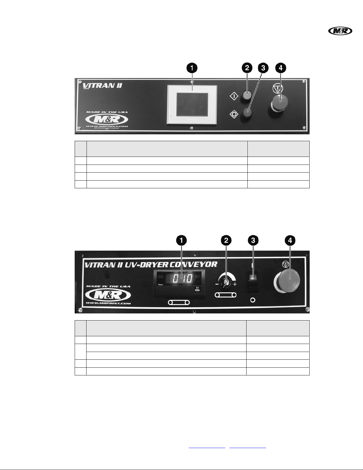
V.112910 Vitran II™
Control Panel (UL & CE)
Control Panel (UL & CE)
1
Operator Interface 1038219
2
Green Push Button 1010058E
3
Red Push Button 1010059E
4
Emergency Stop Push Button 1010400
Conveyor Drive Control Panel (UL & CE)
Part Name
Part Numbers
All Models
1
Belt Speed Indicator 1015000
Potentiometer 1012000A
2
Knob 3033006
3
Switch 1010063
4
Emergency Stop Push Button 1010400
Conveyor Drive Control Panel (UL & CE)
Part Name
Part Numbers
All Models
M&R Companies 1N 372 Main St. Glen Ellyn, IL 60137 USA 37
Tel: +630-858-6101 Fax: +630-858-6134 www.mrprint.com | store.mrprint.com
Page 38
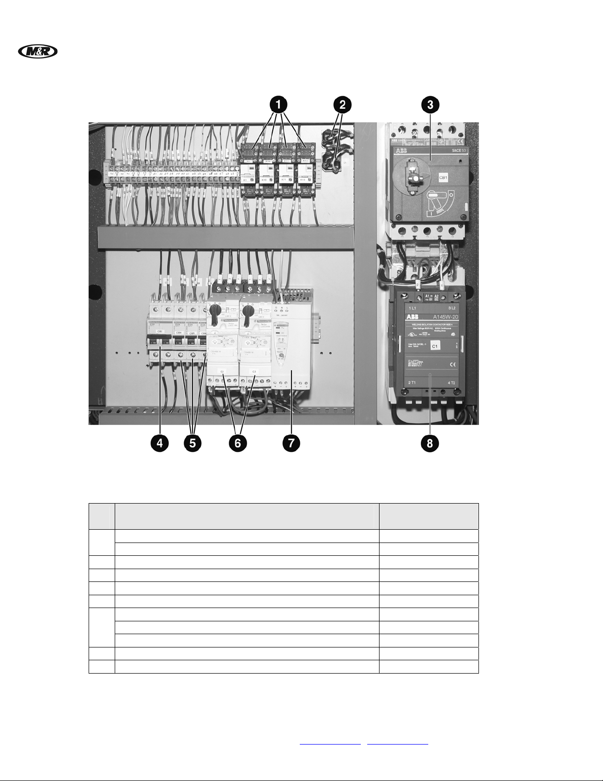
Vitran II
Electrical (UL)
™
V.112910
Note: 208-230V 1Ph. 60Hz. shown. Refer to Schematic Diagrams for Electrical Parts at the beginning of this section before placing
a parts order.
Relay 2 Pole 1010017A
1
Relay Base 2 Pole 1011006A
2
Bridge Rectifier 1010231
3
Circuit Breaker 2 Pole - 100A (CB1) 1004599
4
Circuit Breaker 2 Pole - 5A (CB2) 1006449
5
Circuit Breaker 1 Pole - 2A (CB4-6) 1006441
Contactor 32A (C2, C3) 1011650
6
Motor Starter Protector 1011657A
Over Auxiliary Contactor 1011672B
7
Power Supply 1024131
8
Contactor (C1) 1011172
38 M&R Companies 1N 372 Main St. Glen Ellyn, IL 60137 USA
Tel: +630-858-6101 Fax: +630-858-6134 www.mrprint.com | store.mrprint.com
Electrical (UL & CE)
Part Name
Part Numbers
38” 300W/IN
Page 39
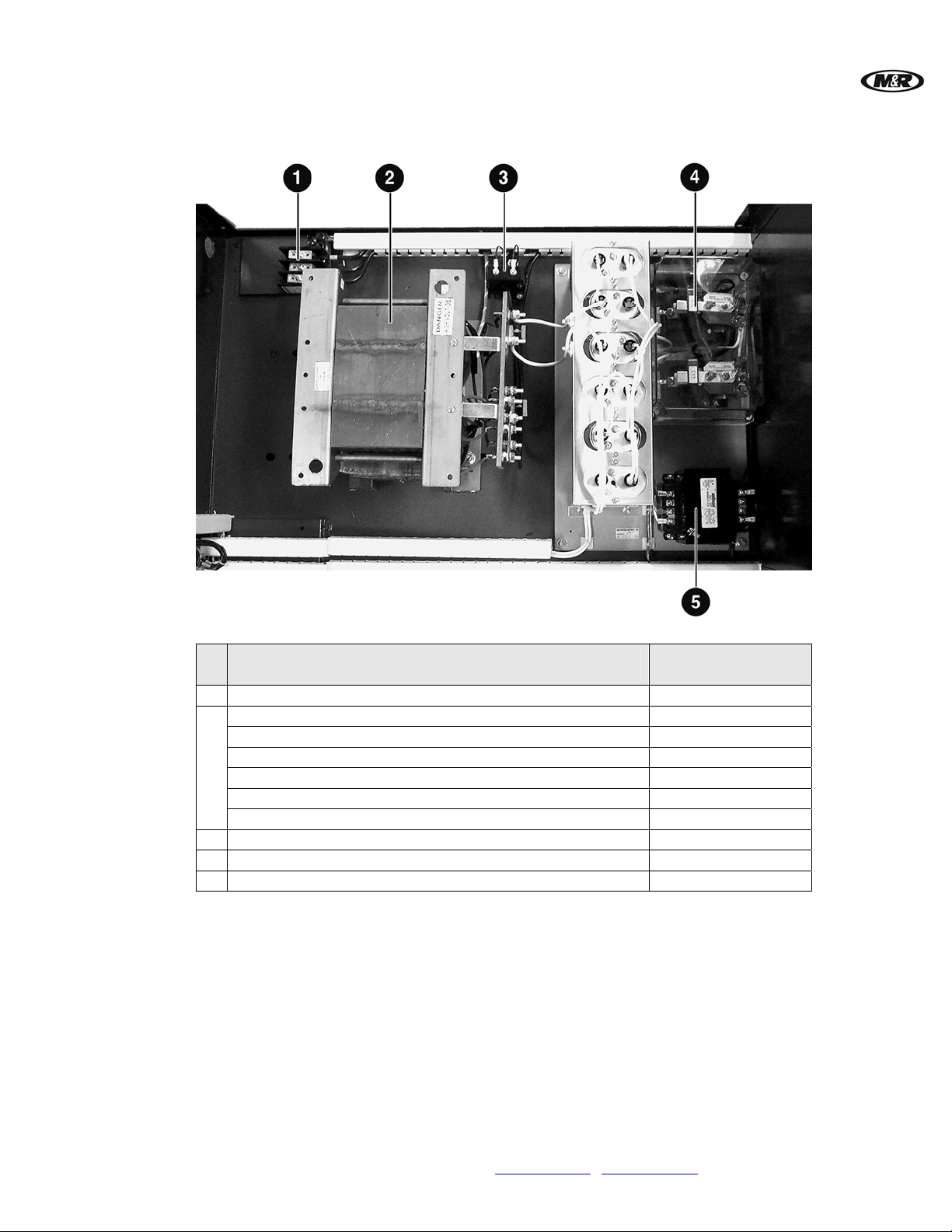
V.112910 Vitran II™
Transformer and Ballast (UL & CE)
1
Terminal Block 1003097
Transformer and Ballast ( UL& CE)
Part Name
Part Numbers
All Models
Ballast and Capacitors 24" Model 1036093
Ballast and Capacitors 38" Model 1036096
Ballast and Capacitors 48" Model 1036099
2
Ballast and Capacitors 54" Model 1036102
Ballast and Capacitors 60" Model 1036104
Ballast and Capacitors 72" Model 1036107
3
Current Transformer 1019016D
4
UV Lamp Contactor 1010230
5
Control Transformer 1019020
M&R Companies 1N 372 Main St. Glen Ellyn, IL 60137 USA 39
Tel: +630-858-6101 Fax: +630-858-6134 www.mrprint.com | store.mrprint.com
Page 40
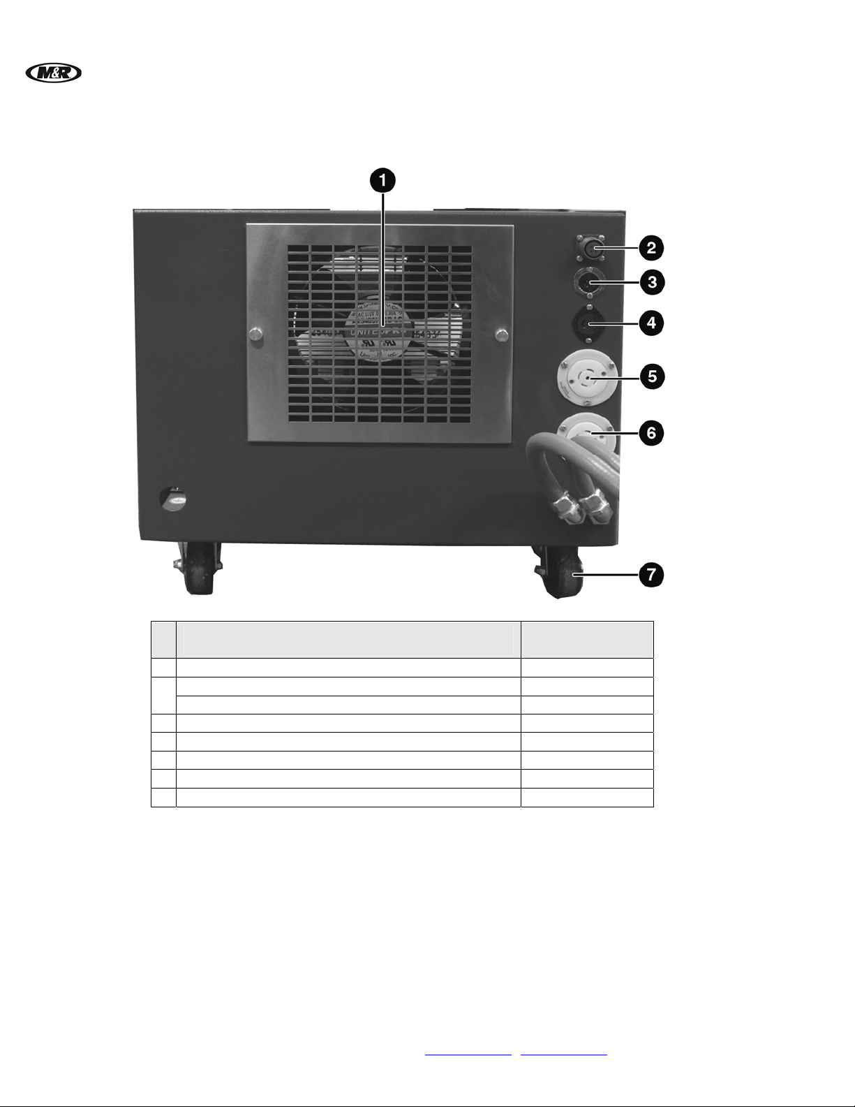
Vitran II
Power Cabinet (UL & CE)
™
V.112910
1
Vent Fan with Guard and Filter 1009054
Socket 1020048A
2
Plug 1020048C
3
Flanged Outlet 1020118
4
Flanged Outlet 1020117
5
Outlet 3 Ph 20 Amps 1017376
6
Outlet 3 Ph 30 Amps 1017378
7
Caster 3037010
Power Cabinet (UL & CE)
Part Name
Part Numbers
All Models
40 M&R Companies 1N 372 Main St. Glen Ellyn, IL 60137 USA
Tel: +630-858-6101 Fax: +630-858-6134 www.mrprint.com | store.mrprint.com
Page 41
V.112910 Vitran II™
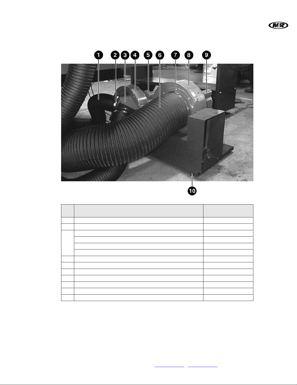
Exhaust/Vacuum Turbines and Hoses (UL & CE)
1
2
Exhaust/Vacuum Turbines and Hoses (UL & CE)
Part Name
5" Diameter Hose 3058020
5" Hose Clamp 3039011
Exhaust Hose Adapter 24" Model 9033263
Exhaust Hose Adapter 38" Model 9033363
3
Exhaust Hose Adapter 48" Model 9033463
Exhaust Hose Adapter 54" Model 9033563
4
Exhaust Blower Assembly 1016020
5
Exhaust Blower Motor 1008086
6
10" Diameter Hose 3058018
7
10" Hose Clamp 3039012
8
Vacuum Turbine Blower 1016019
9
Vacuum Turbine Motor 1008085
10
Leveling Pad 3037011
Part Numbers
All Models
M&R Companies 1N 372 Main St. Glen Ellyn, IL 60137 USA 41
Tel: +630-858-6101 Fax: +630-858-6134 www.mrprint.com | store.mrprint.com
Page 42
™
Vitran II
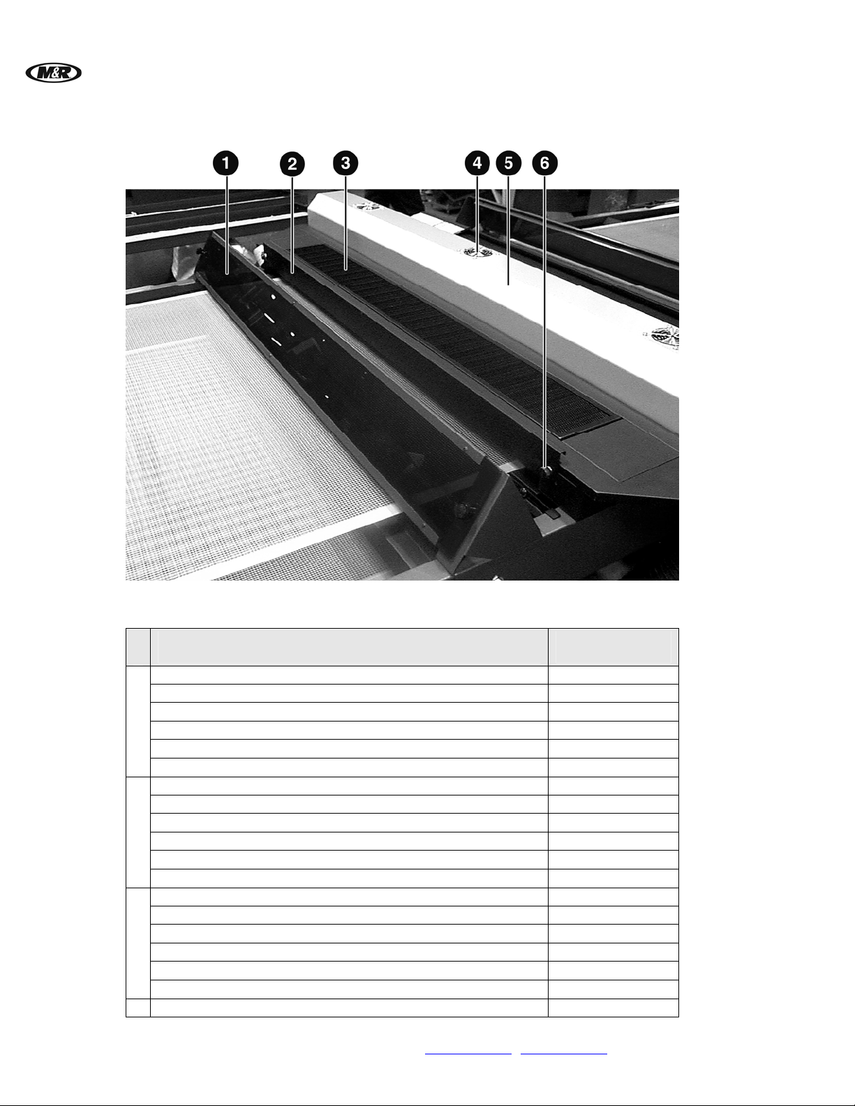
Lamp and Conveyor Belt (UL & CE)
V.112910
UV Light Filter 24" Model 9033295
UV Light Filter 38" Model 9033395
UV Light Filter 48" Model 9033495
1
UV Light Filter 54" Model 9033595
UV Light Filter 60" Model 9033695
UV Light Filter 72" Model 9033795
Delivery Door 24" Model 9033211
Delivery Door 38" Model 9033311
Delivery Door 48" Model 9033411
2
Delivery Door 54" Model 9033511
Delivery Door 60" Model 9033611
Delivery Door 72" Model 9033711
Lamp Housing Chevron 24" Model 9033219-A
Lamp Housing Chevron 38" Model 9033319-A
Lamp Housing Chevron 48" Model 9033419-A
3
Lamp Housing Chevron 54" Model 9033519-A
Lamp Housing Chevron 60" Model 9033619-A
Lamp Housing Chevron 72" Model 9033719-A
4
3" Vent Guard 1009007
Lamp and Conveyor Belt (UL & CE)
Part Name
Part Numbers
All Models
42 M&R Companies 1N 372 Main St. Glen Ellyn, IL 60137 USA
Tel: +630-858-6101 Fax: +630-858-6134 www.mrprint.com | store.mrprint.com
Page 43
V.112910 Vitran II™
Lamp Housing 24" Model 9033201
Lamp Housing 38" Model 9033301
Lamp Housing 48" Model 9033401
5
Lamp Housing 54" Model 9033501
Lamp Housing 60" Model 9033601
Lamp Housing 72" Model 9033701
6
Adjustment Knob with Screw 3070000
UV Lamp 24" Model 1036010A
UV Lamp 38" Model 1036000A
UV Lamp 48" Model 1036001A
7
UV Lamp 54" Model 1036002A
UV Lamp 60" Model 1036002B
UV Lamp 72" Model 1036003A
Conveyor Belt 24" Model 8999960
Conveyor Belt 38" Model 8999966
Conveyor Belt 48" Model 8999962
8
Conveyor Belt 54" Model 8999964
Conveyor Belt 60" Model 8999963
Conveyor Belt 72" Model 8999965
M&R Companies 1N 372 Main St. Glen Ellyn, IL 60137 USA 43
Tel: +630-858-6101 Fax: +630-858-6134 www.mrprint.com | store.mrprint.com
Page 44
™
Vitran II
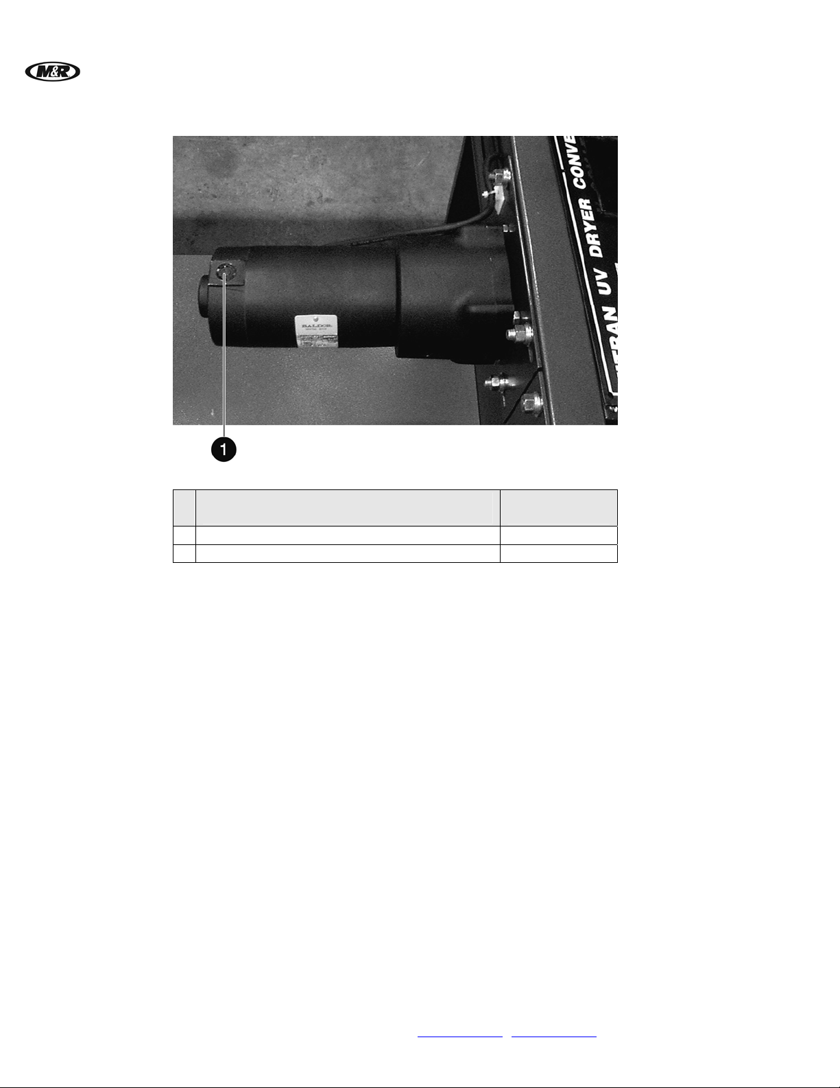
Conveyor Drive Motor (UL & CE)
V.112910
1
2
Conveyor Drive Motor (UL & CE)
Part Name
Conveyor Drive Motor 1008075
Replacement Brushes (Pair) 1008001A
Part Numbers
All Models
44 M&R Companies 1N 372 Main St. Glen Ellyn, IL 60137 USA
Tel: +630-858-6101 Fax: +630-858-6134 www.mrprint.com
| store.mrprint.com
 Loading...