

Page 1
+V
IN
–V
IN
+V
OUT
PWM
*
COMMON
P O W E R E L E C T R O N I C S D I V I S I O N
Single Output
UWR Models
Miniature, 1" x 1"
For full details go to
www.cd4power.com/rohs
Features
■
Small size, 1" x 1" x 0.45"
■
Full 5 Watts output power
■
No external components required
■
Drop-in replacements for many
standard, 2" x 1" DC/DC’s
■
Wide input voltage ranges:
18-36V or 36-72V
■
5, 12, or 15V outputs
■
Guaranteed efficiencies to 80%
■
Fully regulated and isolated
(1000Vdc guaranteed)
■
Output overvoltage protection and
current limiting
■
–25 to +95oC operating temperature
■
Shielded cases (5 sides)
■
UL 1950, CSA 22.2 No. 234, IEC 950
■
Modifications and customs for OEM's
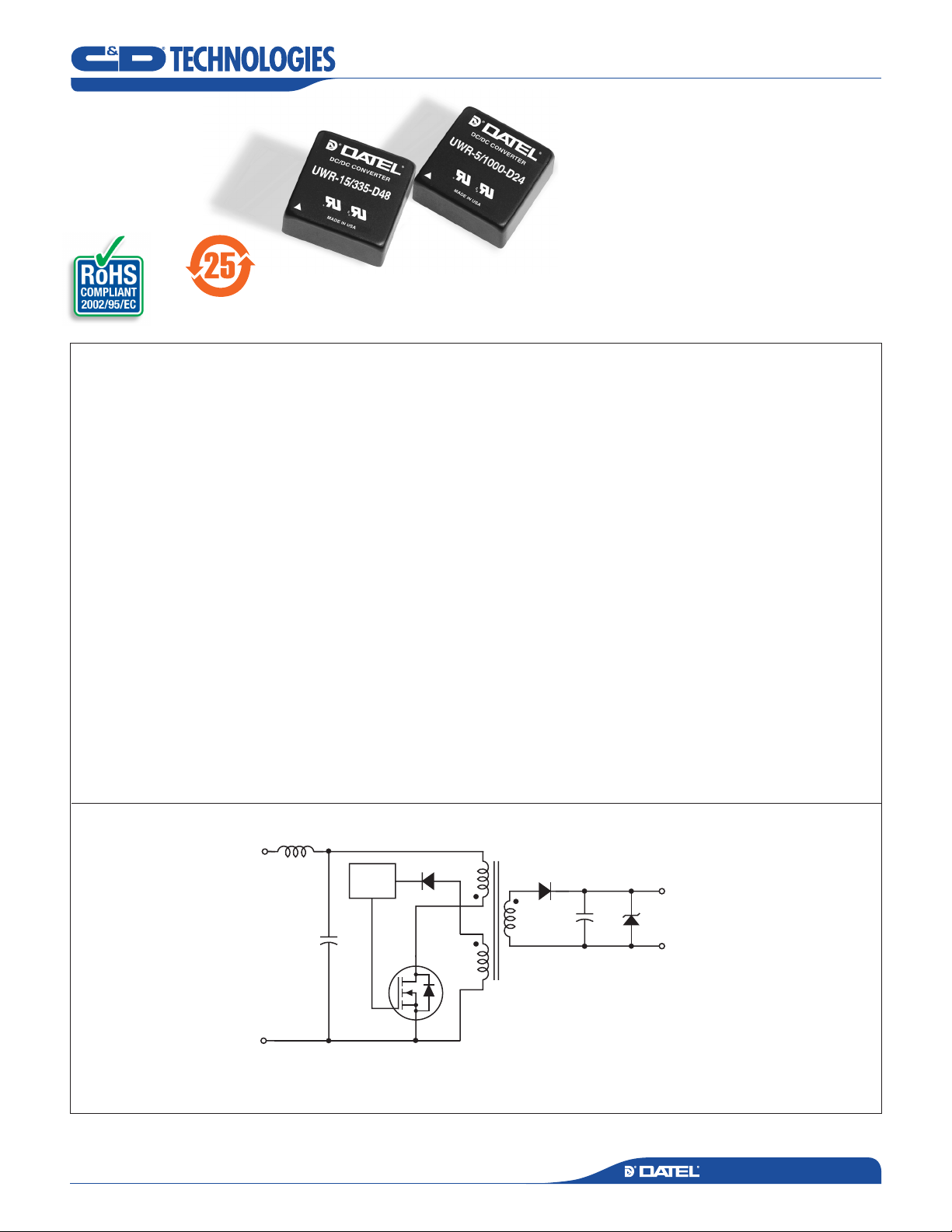
5 Watt, DC/DC Converters
The migration to distributed power is accelerating. The critical need for accurate
voltages, tight regulation and rapid transient response is propelling the move to power
processing at the "point-of-use" with low-power DC/DC converters physically located
right at their loads.
DATEL’s miniature, full featured, 5 Watt UWR Models were specifically designed
for today’s demanding distributed power architectures in aerospace, marine, telecom
and computer applications. The converters' low cost, small size (1" x 1" x 0.45") and
full 5 Watt output capability give system architects unprecedented design and layout
flexibility.
Occupying less than 0.5in3 total volume, these extremely compact, fully regulated
and isolated (1000Vdc guaranteed) modules are available with either 5, 12 or 15 Volt
outputs. Input voltage ranges are either 18-36 Volts ("D24" models) or 36-72 Volts
("D48" models).
Although their overall size is 50-75% smaller than many similarly rated power
modules, these 1" x 1" UWR Models are exact, drop-in, pin-for-pin replacements for
many standard 2" x 1" and 2" x 2", 5 Watt modules. They achieve their small size and
low cost by exploiting a novel feedback approach that does not depend upon traditional optocoupler techniques.
All models are 5-side shielded and have a non-conductive baseplate that permits
pc-card runs to be placed beneath the package. Units are assembled using highspeed automated SMT techniques and are fully encapsulated with thermally conductive potting compound. Every unit is electrically tested before and after encapsulation,
100% burned-in under full load, hi-pot tested, and final-electrical tested prior to shipment. Every unit meets DATEL’s traditional high standards for quality and long-term
reliability.
Figure 1. Simplified Schematic
* "D24" models only
Typical topology is shown
D C / D C C O N V E R T E R S
www.cd4power.comwww.cd4power.com
MDC_UWR5W_A01 Page 1 of 6
Page 2
P O W E R E L E C T R O N I C S D I V I S I O N
Output Power (Watts)
Ambient Temperature (°C)
–25 0 35 40 45 50 55 60 65 70 75 80 85 90 95
5
4.5
4
3.5
3
2.5
2
1.5
1
0.5
0
METAL CASE
INSULA TED BASE
0.040 ± 0.002 DIA.
(1.016 ±0.051 )
1.00
(25.40)
0.45
(11.43)
0.20 M IN.
(5.08)
0.200
(5.08)
0.10
(2.54)
1.00
(25.40)
0.800
(20.32)
0.100
(2.54)
0.800
(20.32)
0.200
(5.08)
0.400
(10.16)
0.10
(2.54)
BOTTO M VIE W
3
1
2
4
6
5
Performance Specifications and Ordering Guide
UWR Models
Single Output, Miniature, 1" x 1", 5 Watt, DC/DC Converters
➀
Input
Range
(Volts)Model
IIN ➃
(mA, Max.)Load ➂
Efficiency
(Min.)
(Volts)
VOUT
IOUT
(mA, Max.)
Output
Ripple/Noise ➁
(mVp-p, Max.)
Regulation (Max.)
Line
VIN Nom.
(Volts)
UWR-5/1000-D24 5 1000 120 ±2% ±2% 24 18-36 25/282 75% C7, P3
UWR-5/1000-D48 5 1000 120 ±2% ±2% 48 36-72 25/141 75% C7, P3
UWR-12/420-D24 12 420 150 ±2% ±2% 24 18-36 25/265 80% C7, P3
UWR-12/420-D48 12 420 150 ±2% ±2% 48 36-72 25/133 80% C7, P3
UWR-15/335-D24 15 335 150 ±2% ±2% 24 18-36 25/264 80% C7, P3
UWR-15/335-D48 15 335 150 ±2% ±2% 48 36-72 25/132 80% C7, P3
➀ Typical at TA = +25°C under nominal line voltage and full-load conditions unless otherwise noted.
➁ Ripple/Noise (R/N) measured over a 20MHz bandwidth.
➂ 20% to 100% load.
➃ Nominal line voltage, no-load/full-load conditions.
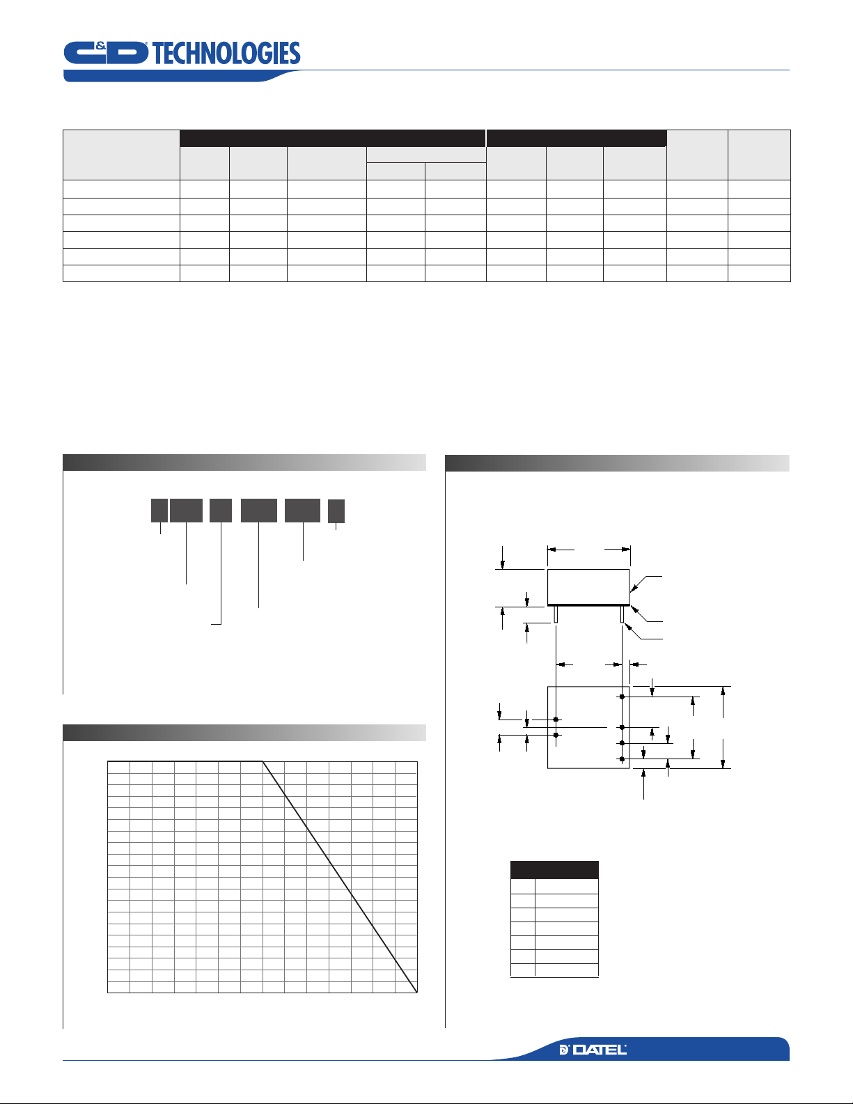
P A R T N U M B E R S T R U C T U R E
15U WR 335 D24
-
Output Configuration:
U = Unipolar
Wide Range Input
Nominal Output Voltage
5, 12 or 15 Volts
/
-
-
Input Voltage Range:
D24 = 18-36 Volts (24V nominal)
D48 = 36-72 Volts (48V nominal)
Maximum Output Current
in mA
C
RoHS-6
compliant*
M E C H A N I C A L S P E C I F I C A T I O N S
Case C7
Package
(Case,
Pinout)
T E M P E R A T U R E D E R A T I N G
www.cd4power.comwww.cd4power.com
* Contact C&D Technologies (Datel)
for availability.
I/O Connections
Pin
Function P3
1
+Input
2
–Input
3
+Output
4
No Pin
5
No Pin
6
Common
Notes:
For "D24" models, the case
is connected to pin 2 (–VIN).
For "D48" models, the case
is connected to pin 1 (+VIN).
D C / D C C O N V E R T E R S
MDC_UWR5W_A01 Page 2 of 6
Page 3

P O W E R E L E C T R O N I C S D I V I S I O N
Performance/Functional Specifications
Typical @ TA = +25°C under nominal line voltage and full-load conditions, unless noted. ➀
Input
Input Voltage Range:
"D24" Models 18-36 Volts (24V nominal)
"D48" Models 36-72 Volts (48V nominal)
Input Current See Ordering Guide
Input Filter Type ➁ LC on "D24" models
C on "D48" models
Reverse-Polarity Protection Yes (Instantaneous, 6A maximum)
Output
VOUT Accuracy (50% load):
5V Outputs ±1.5%, maximum
12/15V Outputs ±1%, maximum
Temperature Coefficient ±0.02% per °C
Ripple/Noise (20MHz BW) ➁ See Ordering Guide
Line Regulation See Ordering Guide
Load Regulation See Ordering Guide
Efficiency See Ordering Guide
Isolation Voltage ➂ 1000Vdc, minimum
Current Limiting Auto-recovery
Overvoltage Protection Zener/transorb clamp
Dynamic Characteristics
Transient Response (50% load step) 500µsec max. to ±2% of final value
Switching Frequency 170kHz (±10kHz)
Environmental
Operating Temperature (Ambient): ➃
Without Derating –25 to +60°C
With Derating to +95°C (See Derating Curve)
Storage Temperature –55 to +125°C
Flammability UL94V-0
Physical
Dimensions 1" x 1" x 0.45" (25.4 x 25.4 x 11.4mm)
Shielding 5-sided
Case Connection:
"D24" Models Pin 2 (–VIN)
"D48" Models Pin 1 (+VIN)
Case Material Corrosion resistant steel with
non-conductive,epoxy-based, black
enamel finish and plastic baseplate
Pin Material Gold plate over copper alloy
Weight 0.7 ounces (20 grams)
➀ These power converters require a minimum 20% loading to maintain specified regulation.
Operation under no-load conditions will not damage these devices; however
they may not meet all listed specifications.
➁ Application-specific input/output filtering can be recommended and perhaps added
internally upon request. Contact DATEL Applications Engineering for details.
➂ Units can be screened or modified for higher guaranteed isolation voltages.
Contact DATEL Applications Engineering for details.
➃ Units can be warranted or screened for lower-temperature operation.
Contact DATEL Applications Engineering for details.
UWR Models
Single Output, Miniature, 1" x 1", 5 Watt, DC/DC Converters
Absolute Maximum Ratings
Input Voltage:
"D24" Models 40 Volts
"D48" Models 80 Volts
Input Reverse-Polarity Protection Current must be < 6A. Brief
duration only. Fusing recommended.
Output Overvoltage Protection:
5V Outputs 6.8 Volts, limited duration
12V Outputs 15 Volts, limited duration
15V Outputs 18 Volts, limited duration
Output Current Current limited. Max. current and
short-circuit duration are model
dependent.
Storage Temperature –55 to +125°C
Lead Temperature (soldering, 10 sec.) +300°C
These are stress ratings. Exposure of devices to any of these conditions may adversely
affect long-term reliability. Proper operation under conditions other than those listed in the
Performance/Functional Specifications Table is not implied.
T E C H N I C A L N O T E S
Floating Outputs
Since these are isolated DC/DC converters, their outputs are "floating." Us-
ers may ground either the Common (pin 6) for normal usage or the positive
side (+Output, pin 3) to effectively reverse the output polarity.
Filtering and Noise Reduction
All UWR 5 Watt DC/DC Converters achieve their rated ripple and noise
specifications without the use of external input/output capacitors. In critical
applications, input/output ripple and noise may be further reduced by install-
ing low-ESR, tantalum or electrolytic capacitors across the input
and/or output terminals. The capacitors should be located as close to the
power converters as possible. Typical values are listed below. In many ap-
plications, using values greater than those listed will yield better results.
To Reduce Input Ripple
"D24" Models 20µF, 50V
"D48" Models 10µF, 100V
To Reduce Output Ripple
5V Outputs 47µF, 10V, Low ESR
12/15V Outputs 33µF, 20V, Low ESR
In critical, space-sensitive applications, DATEL may be able to tailor the in-
ternal input/output filtering of these units to meet your specific requirements.
Contact our Applications Engineering Group for additional details.
Input Fusing
Certain applications and/or safety agencies may require the installation of
fuses at the inputs of power conversion components. For DATEL UWR
5 Watt DC/DC Converters, you should use slow-blow type fuses with values
no greater than 0.5A.
www.cd4power.comwww.cd4power.com
D C / D C C O N V E R T ER S
MDC_UWR5W_A01 Page 3 of 6
Page 4

P O W E R E L E C T R O N I C S D I V I S I O N
81
80
79
78
77
76
75
Efficiency (%)
Input Voltage (Volts)
Efficiency vs. Input Voltage
(Full-load conditions. Guaranteed efficiency = 75% at V
IN
= 24V )
18 21 24 27 30 33 36
82
80
78
76
74
72
70
Efficiency (%)
Output Current (Amps)
Efficiency vs. Output Load
(VIN = nominal = 24V. Guaranteed efficiency at full load = 75%)
0.2 0.4 0.6 0.8 1.0
5.15
5.10
5.05
5.00
4.95
4.90
4.85
Output Voltage (Volts)
Input Voltage (Volts)
Output Voltage vs.Input Voltage
(Full-load conditions. No mi nal
V
OUT
= 5V)
18 21 24 27 30 33 36
5.06
5.04
5.02
5.00
4.98
4.96
4.94
Output Voltage (Volts)
Output Current (Amps)
Output Voltage vs. Output Load
(VIN = nominal = 24V. Nominal V
OUT
= 5V)
0.2 0.4 0.6 0.8 1.0
Typical Performance Curves (TA = +25°C)
The performance curves below were derived from actual test data for a single model number (UWR-5/1000-D24).
Since all devices in this Series have the same circuit topology, the performance curves are representative of all devices.
E F F I C I E N C Y V S . I N P U T V O L T A G E A N D O U T P U T L O A D
UWR Models
Single Output, Miniature, 1" x 1", 5 Watt, DC/DC Converters
L I N E R E G U L A T I O N L O A D R E G U L A T I O N
www.cd4power.comwww.cd4power.com
D C / D C C O N V E R T ER S
MDC_UWR5W_A01 Page 4 of 6
Page 5

P O W E R E L E C T R O N I C S D I V I S I O N
UWR-5/1000-D24 Radiated Emissions
FCC Part 15 Class B, 3 Meters
Converter Output = 5Vdc @ 800mA
80
70
60
50
40
30
20
10
0
–10
–20
Frequency (MHz)
100
1000
Radiated Emissions
FCC Class B Limit
Radiated Emissions (dBµV/M)
UWR-5/1000-D24 Radiated Emissions
EN 55022 Class B, 10 Meters
Converter Output = 5Vdc @ 800mA
80
70
60
50
40
30
20
10
0
–10
–20
Frequency (MHz)
100
1000
Radiated Emissions
EN 55022 Class B Limit
Radiated Emissions (dBµV/M)
C U S T O M C A P A B I L I T I E S
UWR Models
Single Output, Miniature, 1" x 1", 5 Watt, DC/DC Converters
E M I R A D I A T E D E M I S S I O N S
DATEL’s world-class design, development and manufacturing team stands
ready to work with you to deliver the exact power converter you need for
your demanding, large volume, OEM applications. And ... we’ll do it on time
and within budget!
Our experienced applications and design staffs; quick-turn prototype
capability; highly automated, SMT assembly facilities; and in-line SPC qual-
ity-control techniques combine to give us the unique ability to design and
deliver any quantity of power converters to the highest standards of quality
and reliability.
We have compiled a large library of DC/DC designs that are currently used
in a variety of telecom, medical, computer, railway, aerospace and industrial
If you’re designing with EMC in mind, please note that all of DATEL’s UWR
5 Watt DC/DC Converters have been characterized for radiated and
conducted emissions in our new EMI/EMC laboratory. Testing is conducted
in an EMCO 5305 GTEM test cell utilizing EMCO automated EMC test
software. Radiated emissions are tested to the limits of FCC Part 15, Class
B and CISPR 22 (EN 55022), Class B. Correlation to other specifications
can be supplied upon request. Radiated emissions plots to FCC and CISPR
22 for model UWR-5/1000-D24 appear below. Its performance is typical of
all models in the Family. Published EMC test reports are available for each
model number. Contact DATEL’s Applications Engineering Department for
details.
applications. We may already have the converter you need.
Contact us. Our goal is to provide you the highest-quality, most cost-effec-
tive power converters available.
www.cd4power.comwww.cd4power.com
D C / D C C O N V E R T ER S
MDC_UWR5W_A01 Page 5 of 6
Page 6

®
P O W E R E L E C T R O N I C S D I V I S I O N
MDC_UWR5W_A01 Page 6 of 6
UWR Models
Single Output, Miniature, 1" x 1", 5 Watt, DC/DC Converters
C&D Technologies, Inc.
11 Cabot Boulevard, Mansfield, MA 02048-1151 U.S.A.
Tel: (508) 339-3000 (800) 233-2765 Fax: (508) 339-6356
www.cd4power.com email: sales@cdtechno.com
ISO 9001 REGISTERED
© 2006 C&D Technologies, Inc.
C&D Technologies, Inc. makes no representation that the use of its products in the circuits described herein, or the use of other technical
information contained herein, will not infringe upon existing or future patent rights. The descriptions contained herein do not imply the
granting of licenses to make, use, or sell equipment constructed in accordance therewith. Specifications are subject to change without
notice.
www.cd4power.com
DS-0316 06/07
USA: Tucson (Az), Tel: (800) 547 2537, email: sales@cdtechno.com
Canada: Toronto, Tel: (866) 740 1232, email: toronto@cdtechno.com
United Kingdom: Milton Keynes, Tel: +44 (0)1908 615232, email: mk@cdtechno.com
France: Montigny Le Bretonneux, Tel: +33 (0)1 34 60 01 01, email: france@cdtechno.com
Germany: München, Tel: +49 (0)89-544334-0, email: ped.munich@cdtechno.com
Japan: Tokyo, Tel: 3-3779-1031, email: sales_tokyo@cdtechno.com
Osaka, Tel: 6-6354-2025, email: sales_osaka@cdtechno.com
Website: www.cd4power.jp
China: Shanghai, Tel: +86 215 027 3678, email: shanghai@cdtechno.com
Guangzhou, Tel: +86 208 221 8066, email: guangzhou@cdtechno.com
D C / D C C O N V E R T ER S
 Loading...