

Page 1
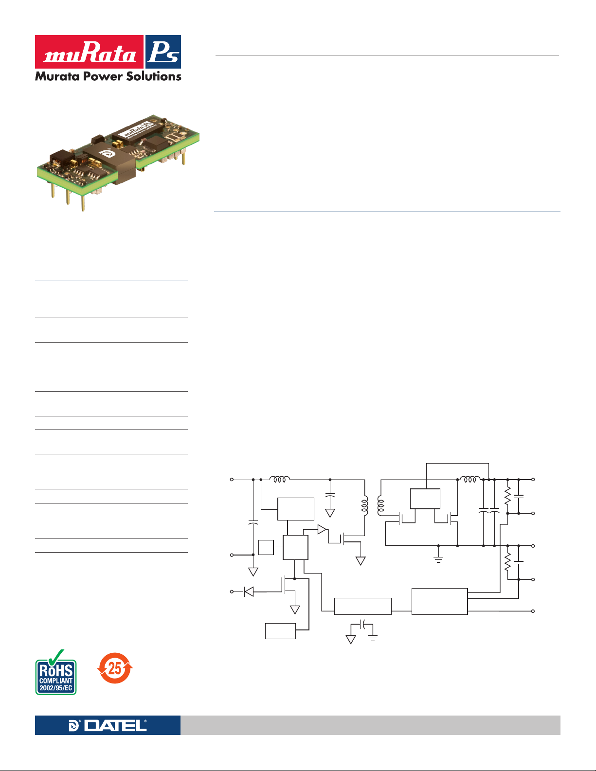
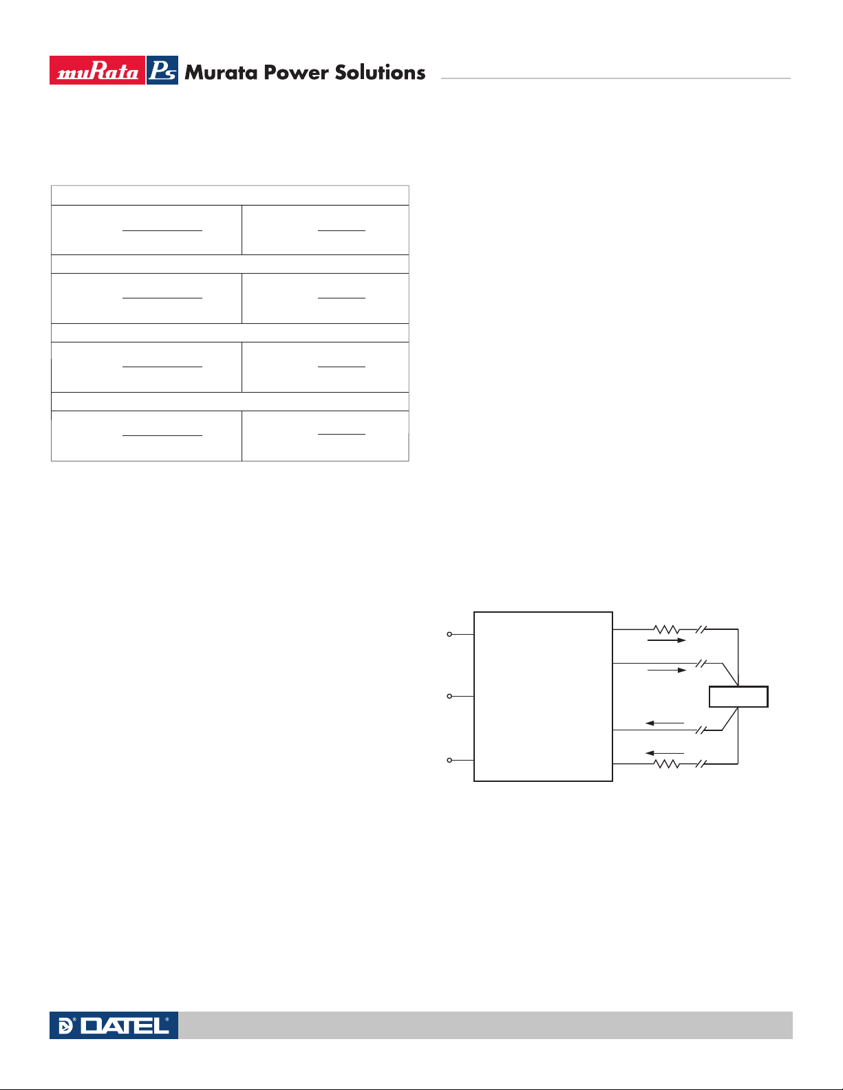
Typical unit
+SENSE
+V
OUT
−V
OUT
−SENSE
TRIM
–V
IN
+V
IN
ON/OFF
CONTROL
SWITCH
DRIVE
Typical topology is shown.
REFERENCE
AMPLIFIER,
TRIM AND FEEDBACK
VOLTAGE
REGULATOR
SS
UV, OT
ISOLATION
PWM
FEATURES
n
Industry-standard through-hole eighth-brick
package with 0.9" x 2.3" x 0.36" outline
dimensions
n
Choice of two wide input ranges, 9 - 36 Vdc or
18-75 Vdc
n
Fixed output from 3.3 to 24 Volts DC up to
75 Watts
n
Synchronous rectification yields very high
efficiency and low power dissipation
n
Operating temperature range from -40 to
+85˚C. with derating
n
Up to 1500 Volt DC isolation using Basic insulation
n
Outstanding thermal performance and
derating
n
Extensive self-protection, overtemperature and
overload features with no output reverse
conduction
n
On/Off control, trim and remote sense functions
n
Designed to meet UL/EN/IEC 60950-1, CAN/
CSA-C22.2 No. 60950-1 safety approvals
and FCC RFI/EMI certification
n
Pre-bias operation for startup protection
UWE Series
Wide Input, Isolated
Eighth-Brick DC/DC Converters
The UWE Series "Eighth-Brick" DC/DC Converters are high-current isolated
power modules designed for use in high-density system boards.
PRODUCT OVERVIEW
With dimensions of only 0.9 by 2.3 by 0.36
inches, the UWE series open frame DC/DC converters deliver up to 75 Watts in an industry-standard
“eighth-brick” through-hole package. This format
can plug directly into quarter-brick pinouts. Several
standard fixed-output voltages from 3.3 Vdc to 24
Vdc assure compatibility in embedded equipment,
CPU cards and instrument subsystems. The extended 4-to-1 input power range (9-36V) is ideal for
battery-powered, telecom or portable applications.
Very high efficiency means no fans or temperature
deratings in many applications. An optional thermal
mounting baseplate extends operation into most
conceivable environments.
The synchronous rectifier design uses the
maximum available duty cycle for greatest efficiency and low power dissipation with no reverse
output conduction. Other features include low
on-resistance FET’s, planar magnetics and heavycopper PC boards. These deliver low output noise,
tight line/load regulation, stable no-load operation
and fast load step response. All units are precision
assembled in a highly automated facility with ISOtraceable manufacturing quality standards.
Isolation of 1500 Volts assures safety and fully
differential (floating) operation for greatest application flexibility. On-board Sense inputs compensate
for line drop errors at high output currents. Outputs
are trimmable within ±10% of nominal voltage. The
UWE series are functionally complete.
A wealth of protection features prevents damage
to both the converter and outside circuits. Inputs
are protected from undervoltage and outputs feature short circuit protection, overcurrent and excess
temperature shut down. Overloads automatically
recover using the “hiccup” technique upon fault
removal. The UWE is designed to meet all standard
safety and EMI/RFI certifications. All units meet
RoHS-6 (no lead) hazardous materials certification.
For full details go to
www.murata-ps.com/rohs
www.murata-ps.com Technical enquiries email: [email protected], tel: +1 508 339 3000
Simplified Block Diagram
MDC_UWE Series.A06 Page 1 of 12
Page 2
UWE Series
18
Wide Input, Isolated
Eighth-Brick DC/DC Converters
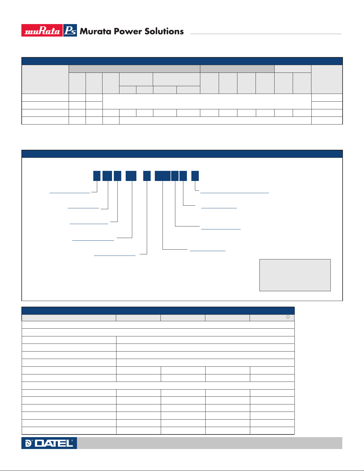
SPECIFICATION SUMMARY AND ORDERING GUIDE
Vo u t
Root Model
UWE-3.3/20-Q12P-C 3.3 20
UWE-5/15-Q12P-C 5.0 15 C77, P32
UWE-12/6-Q12P-C 12.0 6 72 120 180 ±0.125% ±0.05% 12 9-36 75 6.56 90% 91.5% C77, P32
UWE-24/3-Q12P-C 24.0 3 72
Please refer to the part number structure for additonal ordering model numbers and options.
All specifications are at nominal line voltage, nominal output voltage and full load, +25° C.
unless otherwise noted. See detailed specifications.
Output capacitors are 1 µF ceramic || 10 µF electrolytic. Input cap is 100 µF.
(V)
Io u t
(A)
Output Input
R/N (mVp-p) ➂ Regulation
Power
(W)
Please contact Murata Power Solutions for further information.
Iin , no
Vin Nom.
(V)
Range
(V)
load
(mA)
Iin , full
load
(A) Min. Typ.Typ. Max. Line Load
Please contact Murata Power Solutions for further information.
I/O caps are necessary for our test equipment and may not be needed for your application.
Load range: 0.1-3A. This is required only for our test equipment. The converter will operate at
zero output current.
Efficiency
(Case, Pinout)
PART NUMBER STRUCTURE
/
6 P B
Q12-12
-
C
RoHS Hazardous Materials Compliance
C=RoHS-6, standard
Baseplate (optional)
Blank = No baseplate (standard)
B = Baseplate installed (optional special order)
On/Off Control Polarity
P = Positive polarity (standard for Q12 models)
N = Negative polarity (optional special order for Q12 models)
Input Voltage Range
Q12 = 9-36 Volts
Note:
Some model number combinations may
not be available. Contact Murata Power
Solutions for further information.
Unipolar, Single-output
Wide Input Range
Eighth-Brick Package
Nominal Output Voltage
U E -
W
Maximum Rated Output
Current in Amps
Package
C77, P32
C77, P32
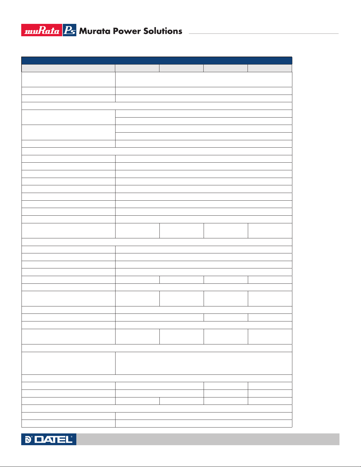
DETAIL SPECIFICATIONS
UWE-3.3/20-Q12 uWE-5/15-Q12 UWE-12/6-Q12 UWE-24/3-Q12
Specs are typical unless noted.
INPUT
Input voltage range See ordering guide
Start-up threshold, Volts 9
Undervoltage shutdown, V. 8
Overvoltage shutdown, V. none
Reflected (back) ripple current, mA pk-pk 40
Suggested external fuse, A 20
Input current
Full load conditions See ordering guide
Inrush transient, A2sec 0.1 A2sec
Input current if output is in short circuit, mA 250
No load, mA 75
Low line (Vin=min.), Amps 8.89
Standby mode, mA 5
Technical enquiries email: [email protected], tel: +1 508 339 3000www.murata-ps.com
MDC_UWE Series.A06 Page 2 of 12
Page 3
Eighth-Brick DC/DC Converters
DETAIL SPECIFICATIONS, CONTIUED
INPUT (continued) UWE-3.3/20-Q12 uWE-5/15-Q12 UWE-12/6-Q12 UWE-24/3-Q12
(Off, UV, OT shutdown)
Internal input filter type
Reverse polarity protection See notes
Recommended external fuse, Amps 20
Remote On/Off control
Positive logic ("P" model suffix)
Negative logic ("N" model suffix)
Current, mA 1
OUTPUT
Voltage output range See ordering guide
Voltage output accuracy ±1% of Vnom., (50% load)
Adjustment range -10 to +10% of Vnom.
Temperature coef ficient ±0.02% of Vout range per °C
Minimum loading No minimum load
Remote sense compensation +10% max.
Ripple/noise (20 MHz bandwidth) See ordering guide
Line/Load regulation See ordering guide
Efficiency See ordering guide
Maximum capacitive loading, μF
low ESR <0.02Ω max., resistive load
Isolation voltage
Input to Output, Volts min. DC 1500
Input to baseplate, Volts min. DC 1500
Baseplate to output, Volts min. DC 750
Isolation resistance, MΩ 100
Isolation capacitance, pF 1000
Isolation safety rating Basic insulation
Current limit inception (98% of
Vout, af ter warmup), Amps
Short circuit protection method Current limiting, hiccup autorestart. Remove overload for recovery.
Short circuit current, Amps 1.5
Short circuit duration Continuous, output shorted to ground. No damage.
Overvoltage protection, Volts
(via magnetic feedback)
DYNAMIC CHAR ACTERISTICS
Dynamic load response, μSec
(50-75-50% load step) to ±1%
of final value
Start-up time
Vin to Vout regulated, mSec 40
Remote On/Off to Vout regulated, mSec 30
Switching frequency, KHz 275 ±25
ENVIRONMENTAL
Calculated MTBF (Telcordia SR-332) 3,755,203 hours (UWE-12/6-Q12N-C)
Calculated MTBF (MIL-HDBK-217N2) 1,239,521 hours (UWE-12/6-Q12N-C)
OFF=Ground pin to +0.8V max.
ON=open pin or +3.5 to +Vin max.
OFF=open pin or +5V to +Vin max.
ON=Ground pin or 0 to +0.8V max.
L-C
4,700
8.5
15
50
UWE Series
Wide Input, Isolated
Technical enquiries email: [email protected], tel: +1 508 339 3000www.murata-ps.com
MDC_UWE Series.A06 Page 3 of 12
Page 4

Eighth-Brick DC/DC Converters
DETAIL SPECIFICATIONS, CONTIUED
ENVIRONMENTAL (continued) UWE-3.3/20-Q12 uWE-5/15-Q12 UWE-12/6-Q12 UWE-24/3-Q12
Operating temperature range
with derating, °C (see Derating cur ves)
Storage temperature range, °C -55 to +125
Thermal protection/shutdown, °C +120
Relative humidity to +85°C/85% non-condensing
PHYSICAL
Outline dimensions See mechanical specs
Pin material Copper alloy
Pin Finish Nickel underplate with gold overplate
Pin diameter, inches 0.04/0.062
Pin diameter, mm 1.016/1.575
Weight, ounces 0.67 0.7 0.7 0.7
Weight, grams 19 20 20 20
Electromagnetic interference (conducted and
radiated, external filter required)
Safety Designed to meet UL/cUL 60950-1, CSA-C22.2 No.60950-1, IEC/EN 60950-1
-40 to +85 with derating
FCC part 15, class B, EN55022
UWE Series
Wide Input, Isolated
SPECIFICATION NOTES
CAUTION: This product is not internally fused. To comply with safety agency cer-
tifications and to avoid injury to personnel or equipment, the user must supply an
external fast-blow fuse to the input terminals. See fuse information.
1 All models are tested and specified with external 1µF and 10µF paralleled ceramic/
tantalum output capacitors and a 100 µF external input capacitor. All capacitors are
low ESR types. These capacitors are necessary to accommodate our test equipment
and may not be required to achieve specified performance in your applications.
However, Murata Power Solutions recommends using these capacitors in your application. All models are stable and regulate within spec under no-load conditions.
All specifications are typical unless noted. General conditions for Specifications are
+25° C, Vin=nominal, Vout=nominal, full load. Adequate airflow must be supplied
for extended testing under power.
2 Input Ripple Current is tested and specified over a 5 Hz to 20 MHz bandwidth. Input
filtering is Cin=33 µF, Cbus=220 µF, Lbus=12 µH.
3 Note that Maximum Power Derating curves indicate an average current at nominal
input voltage. At higher temperatures and/or lower airflow, the DC/DC converter will
tolerate brief full current outputs if the total RMS current over time does not exceed
the Derating curve. All Derating curves are presented at sea level altitude. Be aware
that power dissipation degrades as altitude increases.
4 Mean Time Before Failure is calculated using the Telcordia (Belcore) SR-332 Issue
1, Case 3, Fits 266, ground fixed conditions, Tambient = +30° C, full output load,
natural air convection.
5 The Remote On/Off Control is normally controlled by a switch or open collector or
open drain transistor. But it may also be driven with external logic or by applying
appropriate external voltages which are referenced to Input Common.
6 Short circuit shutdown begins when the output voltage degrades approximately 2%
from the selected setting.
7 The outputs are not intended to sink appreciable reverse current.
8 Output noise may be further reduced by adding an external filter. See I/O Filtering
and Noise Reduction. Larger caps (especially low-ESR ceramic capacitors) may
slow transient response or degrade stability. Use only as much output filtering as
needed to achieve your noise requirements and no more. Thoroughly test your
system under full load with all components installed.
9 All models are fully operational and meet published specifications, including “cold
start” at –40° C. At full power, the package temperature of all on-board components
must not exceed +128° C.
10 Regulation specifications describe the deviation as the line input voltage or output
load current is varied from a nominal midpoint value to either extreme.
11 If the user adjusts the output voltage, accuracy is dependent on user-supplied
trim resistors. To achieve high accuracy, use ±1% or better tolerance metal-film
resistors. If no trim is installed, the converter will achieve its rated accuracy. Do not
exceed maximum power specifications when adjusting the output trim.
12 Output current limit and short circuit protection is non-latching. When the overcur-
rent fault is removed, the converter will immediately recover.
13 Alternate pin length and/or other output voltages may be available under special
quantity order.
14 At zero output current, the output may contain low frequency components which
exceed the ripple specification. The output may be operated indefinitely with no
load.
15 Input Fusing: To ensure reverse input protection with full output load, always con-
nect an external input fast-blow fuse in series with the +Vin input. Use approximately twice the full input current rating at the selected input voltage.
16 “Hiccup” overcurrent operation repeatedly attempts to restart the converter with a
brief, full-current output. If the overcurrent condition still exists, the restart current
will be removed and then tried again. This short current pulse prevents overheating
and damaging the converter. Once the fault is removed, the converter immediately
recovers normal operation.
17 Note that the converter will operate up to the rated baseplate maximum tempera-
ture with the baseplate installed and properly heat sunk. To avoid thermal self-
protection shutdown, do not exceed this maximum baseplate temperature.
18 UWE-24/3-Q12 undervoltage shutdown of 8.0V is at half load.
19 UWE-24/3-Q12 output overvoltage protection requires 0.3A minimum load.
20 Pre-bias operation: Startup will succeed if the output setpoint voltage is higher than
the pre-existing external output voltage.
Technical enquiries email: [email protected], tel: +1 508 339 3000www.murata-ps.com
MDC_UWE Series.A06 Page 4 of 12
Page 5
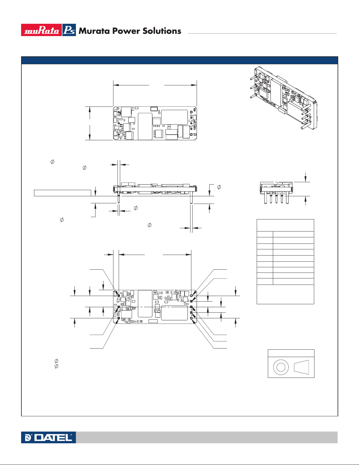
MECHANICAL SPECIFICATIONS—NO BASEPLATE
.062 PINS
0.21 (5.3) @
.062 PINS
0.19 (4.8) @
.071±.002 STANDOFF
AT EACH
.040 PIN
.45
0.38 (9.7)
MAX
SIDE VIEW
.040±.002
AT PINS 1-3, 5-7
.062±.002
AT PINS 4 & 8
TOP VIEW
2.30
(58.4)
0.90 (22.9)
BOTTOM VIEW
PIN 1
PIN 2
PIN 3
PIN 4
PIN 8
PIN 7
PIN 6
PIN 5
REF
.600
.300
.150
.150
2.000
(50.8)
.600
0.15 (3.8)
END VIEW
ISOMETRIC
VIEW
MOUNTING PLANE
I/O CONNECTIONS
Pin
Function
1 - Vin
2 On/Off Control *
3 +Vin
4 - Vout
5 - Sense
6 Trim
7 + Sense
8 + Vout
* The Remote On/Off can
be provided with either
positive (P suffix) or negative
Connect each sense input to its
respective Vout if sense is not
connected at a remote load.
(N suffix) polarity
MATERIAL:
.040 PINS: C26000 BRASS, 3/4 HARD
.062 PINS: C10200 COPPER ALLOY, FULL HARD
FINISH: (ALL PINS)
GOLD (5u"MIN) OVER NICKEL (50u" MIN)
Third Angle Projection
Dimensions are in inches (mm shown for ref. only).
Components are shown for reference only.
Tolerances (unless otherwise specified):
.XX ± 0.02 (0.5)
.XXX ± 0.010 (0.25)
Angles ± 2˚
UWE Series
Wide Input, Isolated
Eighth-Brick DC/DC Converters
Technical enquiries email: [email protected], tel: +1 508 339 3000www.murata-ps.com
MDC_UWE Series.A06 Page 5 of 12
Page 6
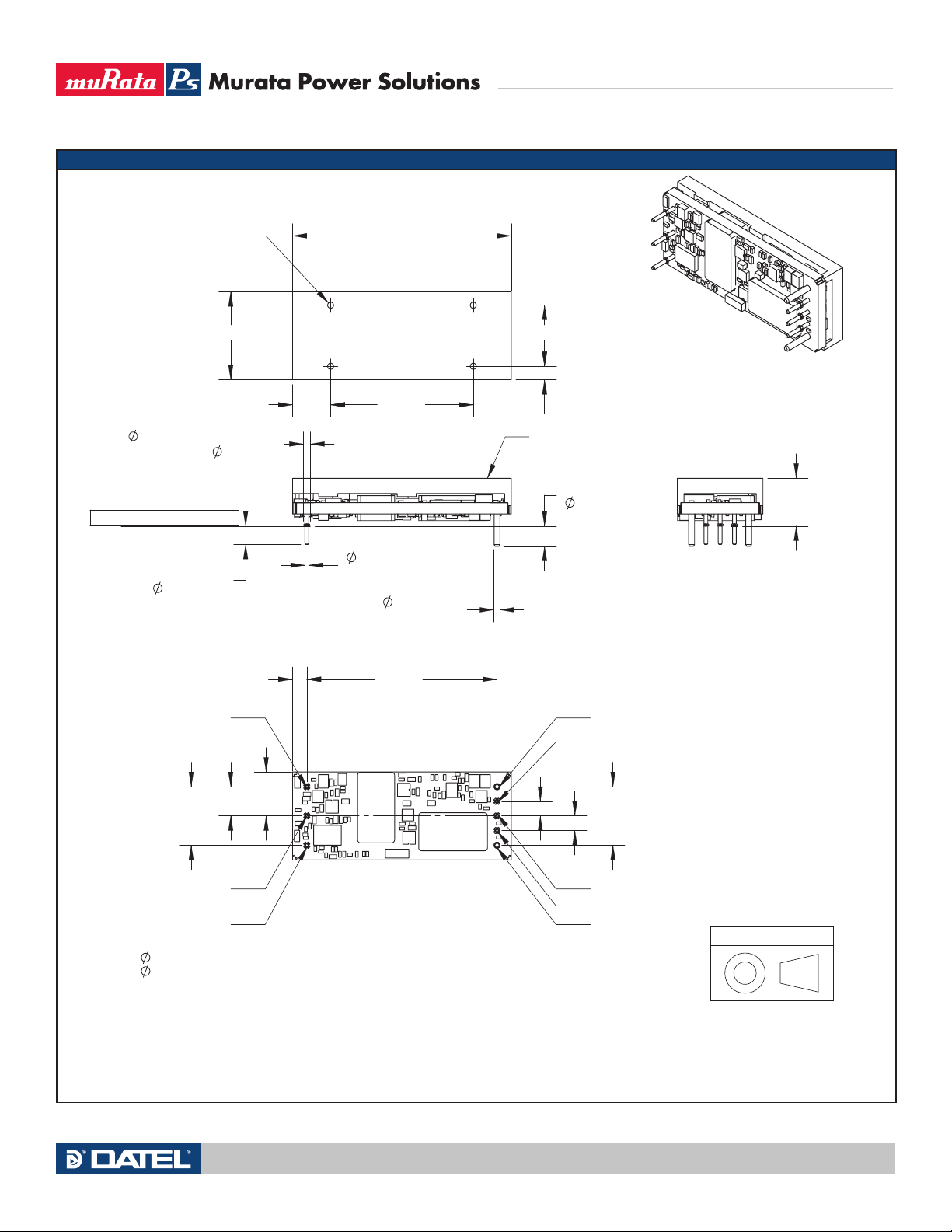
MECHANICAL SPECIFICATIONS (continued)—BASEPLATE INSTALLED
.062 PINS
0.21 (5.3) @
.062 PINS
0.19 (4.8) @
.071±.002 STANDOFF
AT EACH
.040 PIN
0.50 (12.7)
.45
TOP VIEW
0.14 (3.6)
2.30
(58.4)
0.90 (22.9)
1.500.40
.625
M2X0.4 - 6H
.15" MAX SCREW
PENETRATION
4X THRU
SIDE VIEW
ALUMINUM
BASEPLATE
.040±.002
AT PINS 1-3, 5-7
.062±.002
AT PINS 4 & 8
ISOMETRIC
VIEW
END VIEW
BOTTOM VIEW
PIN 1
PIN 2
PIN 3
PIN 4
PIN 8
PIN 7
PIN 6
PIN 5
REF
.600
.300
.150
.150
2.000
(50.8)
.600
0.15 (3.8)
MATERIAL:
.040 PINS: C26000 BRASS, 3/4 HARD
.062 PINS: C10200 COPPER ALLOY, FULL HARD
FINISH: (ALL PINS)
GOLD (5u"MIN) OVER NICKEL (50u" MIN)
MOUNTING PLANE
Third Angle Projection
Dimensions are in inches (mm shown for ref. only).
Components are shown for reference only.
Tolerances (unless otherwise specified):
.XX ± 0.02 (0.5)
.XXX ± 0.010 (0.25)
Angles ± 2˚
UWE Series
Wide Input, Isolated
Eighth-Brick DC/DC Converters
Technical enquiries email: [email protected], tel: +1 508 339 3000www.murata-ps.com
MDC_UWE Series.A06 Page 6 of 12
Page 7
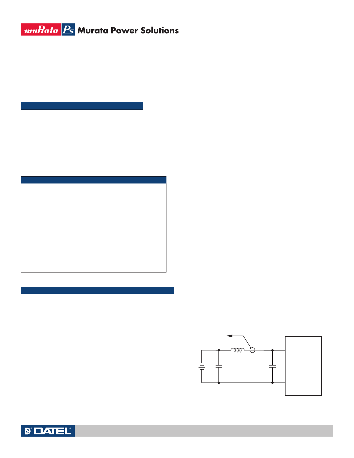
CINVIN CBUS
LBUS
CIN = 33µF, ESR < 700mΩ @ 100kHz
CBUS = 220µF, ESR < 100mΩ @ 100kHz
LBUS = 12µH
+INPUT
–INPUT
CURRENT
PROBE
TO
OSCILLOSCOPE
+
–
Soldering Guidelines
Murata Power Solutions recommends the specifications below when installing these
converters. These specifications vary depending on the solder type. Exceeding these
specifications may cause damage to the product. Be cautious when there is high atmospheric humidity. We strongly recommend a mild pre-bake (100° C. for 30 minutes). Your
production environment may differ; therefore please thoroughly review these guidelines
with your process engineers.
Wave Solder Operations for through-hole mounted products (THMT)
For Sn/Ag/Cu based solders:
Maximum Preheat Temperature 115° C.
Maximum Pot Temperature 270° C.
Maximum Solder Dwell Time 7 seconds
For Sn/Pb based solders:
Maximum Preheat Temperature 105° C.
Maximum Pot Temperature 250° C.
Maximum Solder Dwell Time 6 seconds
Absolute Maximum Ratings
Input Voltage
Continuous or transient, 100 mSec max. 50 Volts
Output Power 66-75 Watts, model dependent
On/Off Control 0V. min. to +Vin max.
Input Reverse Polarity Protection See Fuse section.
Output Current* Devices can withstand sustained
short circuit without damage.
Storage Temperature -40 to +125° C
Absolute maximums are stress ratings. Exposure of devices to any of these conditions
may adversely affect long-term reliability. Proper operation under conditions other than
those listed in the Performance/Functional Specifications Table is not implied or recommended.
* The outputs are not intended to sink appreciable reverse current. If the outputs are
forced to sink excessive current, damage may result.
TECHNICAL NOTES
Input Fusing
Certain applications and/or safety agencies may require the installation of
fuses at the inputs of power conversion components. Fuses should also be
used if the possibility of sustained, non-current-limited, input-voltage polarity
reversals exist. For MPS UWE DC/DC Converters, you should use fast-blow type
fuses, installed in the ungrounded input supply line. Refer to the specifications
for fuse values.
UWE Series
Wide Input, Isolated
Eighth-Brick DC/DC Converters
Start-Up Time
The VIN to VOUT Start-Up Time is the interval of time between the point at which
the ramping input voltage crosses the Start-Up Threshold and the fully loaded
output voltage enters and remains within its specified accuracy band. Actual
measured times will vary with input source impedance, external input/output
capacitance, and load. The UWE Series implements a soft start circuit that
limits the duty cycle of its PWM controller at power up, thereby limiting the
input inrush current.
The On/Off Control to VOUT start-up time assumes the converter has its
nominal input voltage applied but is turned off via the On/Off Control pin. The
specification defines the interval between the point at which the converter is
turned on and the fully loaded output voltage enters and remains within its
specified accuracy band. Similar to the VIN to VOUT start-up, the On/Off Control
to VOUT start-up time is also governed by the internal soft start circuitry and
external load capacitance.
The difference in start up time from VIN to VOUT and from On/Off Control to
VOUT is therefore insignificant.
Input Source Impedance
UWE converters must be driven from a low ac-impedance input source.
The DC/DC’s performance and stability can be compromised by the use of
highly inductive source impedances. For optimum performance, components should be mounted close to the DC/DC converter. If the application
has a high source impedance, low VIN models can benefit from increased
external input capacitance.
I/O Filtering, Input Ripple Current, and Output Noise
All models in the UWE Converters are tested/specified for input reflected ripple
current and output noise using the specified external input/output components/
circuits and layout as shown in the following two figures.
External input capacitors (CIN in Figure 2) serve primarily as energy-storage
elements, minimizing line voltage variations caused by transient IR drops in
conductors from backplane to the DC/DC. Input caps should be selected for bulk
capacitance (at appropriate frequencies), low ESR, and high rms-ripple-current
ratings. The switching nature of DC/DC converters requires that dc voltage
sources have low ac impedance as highly inductive source impedance can affect
system stability. In Figure 2, CBUS and LBUS simulate a typical dc voltage bus. Your
specific system configuration may necessitate additional considerations.
All relevant national and international safety standards and regulations must
be observed by the installer. For system safety agency approvals, the converters must be installed in compliance with the requirements of the end-use
safety standard, e.g., IEC/EN/UL60950-1.
Input Undervoltage Shutdown and Start-Up Threshold
Under normal start-up conditions, devices will not begin to regulate until
the ramping-up input voltage exceeds the Start-Up Threshold Voltage. Once
operating, devices will not turn off until the input voltage drops below the
Undervoltage Shutdown limit. Subsequent re-start will not occur until the input
is brought back up to the Start-Up Threshold. This built in hysteresis prevents
any unstable on/off situations from occurring at a single input voltage.
Figure 2. Measuring Input Ripple Current
Technical enquiries email: [email protected], tel: +1 508 339 3000www.murata-ps.com
MDC_UWE Series.A06 Page 7 of 12
Page 8
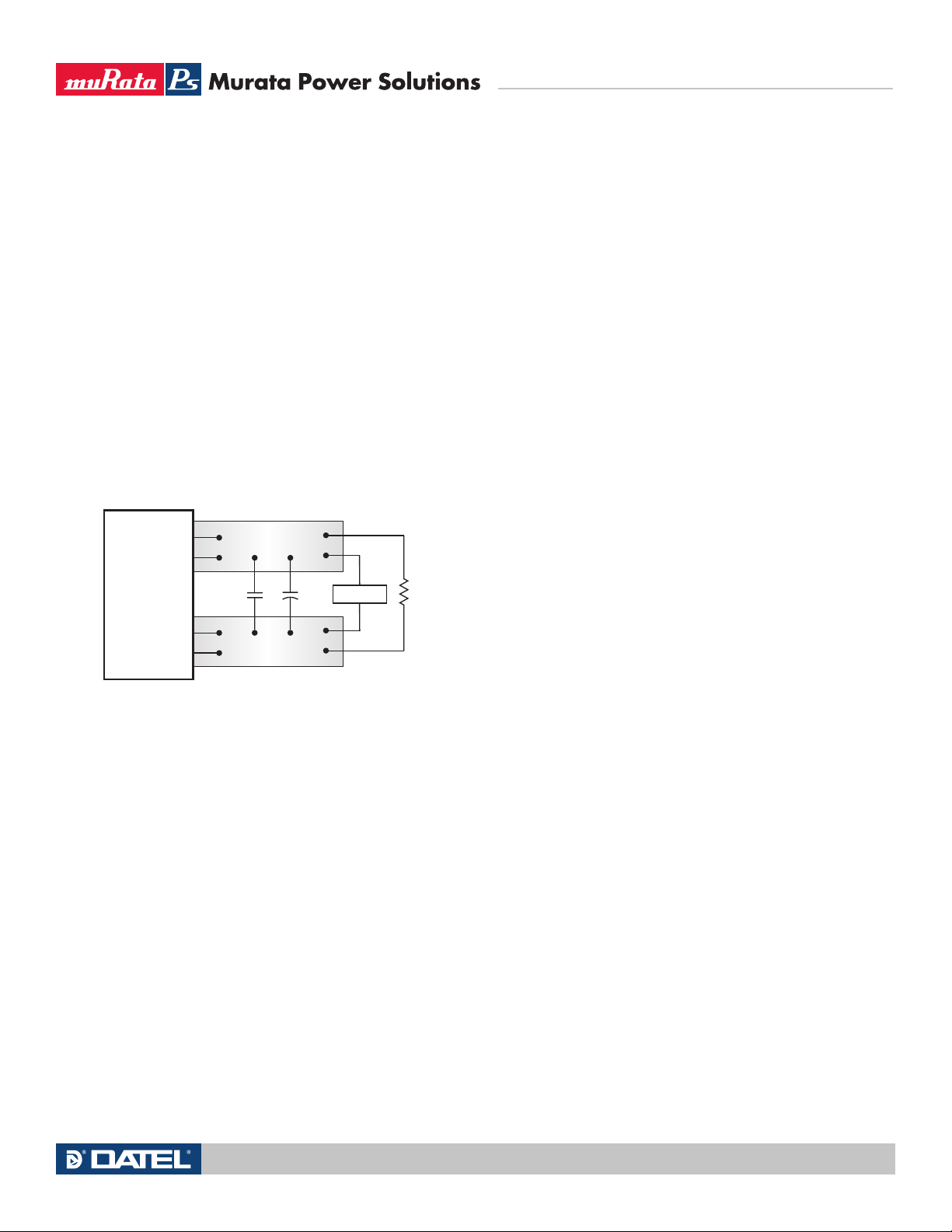
In critical applications, output ripple/noise (also referred to as periodic and
C1
C1 = 0.47µF CERAMIC
C2 = NA
LOAD 2-3 INCHES (51-76mm) FROM MODULE
C2
R
LOAD
COPPER STRIP
COPPER STRIP
SCOPE
+OUTPUT
–OUTPUT
+SENSE
–SENSE
random deviations or PARD) may be reduced below specified limits using filtering techniques, the simplest of which is the installation of additional external
output capacitors. These output caps function as true filter elements and
should be selected for bulk capacitance, low ESR and appropriate frequency
response. All external capacitors should have appropriate voltage ratings and
be located as close to the converter as possible. Temperature variations for all
relevant parameters should also be taken carefully into consideration.
The most effective combination of external I/O capacitors will be a function
of line voltage and source impedance, as well as particular load and layout
conditions. Our Applications Engineers can recommend potential solutions and
discuss the possibility of our modifying a given device's internal filtering to
meet your specific requirements. Contact our Applications Engineering Group
for additional details.
In Figure 3, the two copper strips simulate real-world pcb impedances
between the power supply and its load. In order to minimize measurement
errors, scope measurements should be made using BNC connectors, or the
probe ground should be less than ½ inch and soldered directly to the fixture.
UWE Series
Wide Input, Isolated
Eighth-Brick DC/DC Converters
Thermal Shutdown
These UWE converters are equipped with thermal-shutdown circuitry. If environmental conditions cause the internal temperature of the DC/DC converter to
rise above the designed operating temperature, a precision temperature sensor
will power down the unit. When the internal temperature decreases below the
threshold of the temperature sensor, the unit will self start. See Performance/
Functional Specifications.
Output Overvoltage Protection
UWE output voltages are monitored for an overvoltage condition via magnetic
feedback. The signal is coupled to the primary side and if the output voltage
rises to a level which could be damaging to the load, the sensing circuitry will
power down the PWM controller causing the output voltages to decrease. Following a time-out period the PWM will restart, causing the output voltages to
ramp to their appropriate values. If the fault condition persists, and the output
voltages again climb to excessive levels, the overvoltage circuitry will initiate
another shutdown cycle. This on/off cycling is referred to as "hiccup" mode.
Current Limiting
As soon as the output current increases to substantially above its rated value,
the DC/DC converter will go into a current-limiting mode. In this condition, the
output voltage will decrease proportionately with increases in output current,
thereby maintaining somewhat constant power dissipation. This is commonly
referred to as power limiting. Current limit inception is defined as the point at
which the full-power output voltage falls below the specified tolerance. See
Performance/Functional Specifications. If the load current, being drawn from
the converter, is significant enough, the unit will go into a short circuit condition
as specified under "Performance."
Figure 3. Measuring Output Ripple/Noise (PARD)
Floating Outputs
Since these are isolated DC/DC converters, their outputs are "floating" with
respect to their input. Designers will normally use the –Output as the ground/
return of the load circuit. You can, however, use the +Output as ground/return
to effectively reverse the output polarity.
Minimum Output Loading Requirements
UWE converters employ a synchronous-rectifier design topology and all models
regulate within spec and are stable under no-load to full load conditions.
Operation under no-load conditions however might slightly increase the output
ripple and noise.
Short Circuit Condition
When a converter is in current-limit mode, the output voltage will drop as
the output current demand increases. If the output voltage drops too low, the
magnetically coupled voltage used to develop primary side voltages will also
drop, thereby shutting down the PWM controller. Following a time-out period,
the PWM will restart causing the output voltages to begin ramping to their
appropriate values. If the short-circuit condition persists, another shutdown
cycle will be initiated. This on/off cycling is referred to as "hiccup" mode. The
hiccup cycling reduces the average output current, thereby preventing internal
temperatures from rising to excessive levels. The UWE is capable of enduring
an indefinite short circuit output condition.
Features and Options
On/Off Control
The input-side, remote On/Off Control function can be ordered to operate with
either polarity:
Technical enquiries email: [email protected], tel: +1 508 339 3000www.murata-ps.com
MDC_UWE Series.A06 Page 8 of 12
Page 9
Positive-polarity models (“P" part-number suffix) are enabled when the
ON/OFF CONTROL
CONTROL
+ Vcc
-INPUT
).054
6
##
n).054
/./&&
#/.42/,
LOAD
R2
+OUTPUT
–INPUT
+INPUT
ON/OFF
CONTROL
TRIM
+SENSE
–OUTPUT
–SENSE
20k
5-20
TURNS
LOAD
+OUTPUT
–INPUT
+INPUT
ON/OFF
CONTROL
TRIM
+SENSE
–OUTPUT
–SENSE
LOAD
R1
+OUTPUT
–INPUT
+INPUT
ON/OFF
CONTROL
TRIM
+SENSE
–OUTPUT
–SENSE
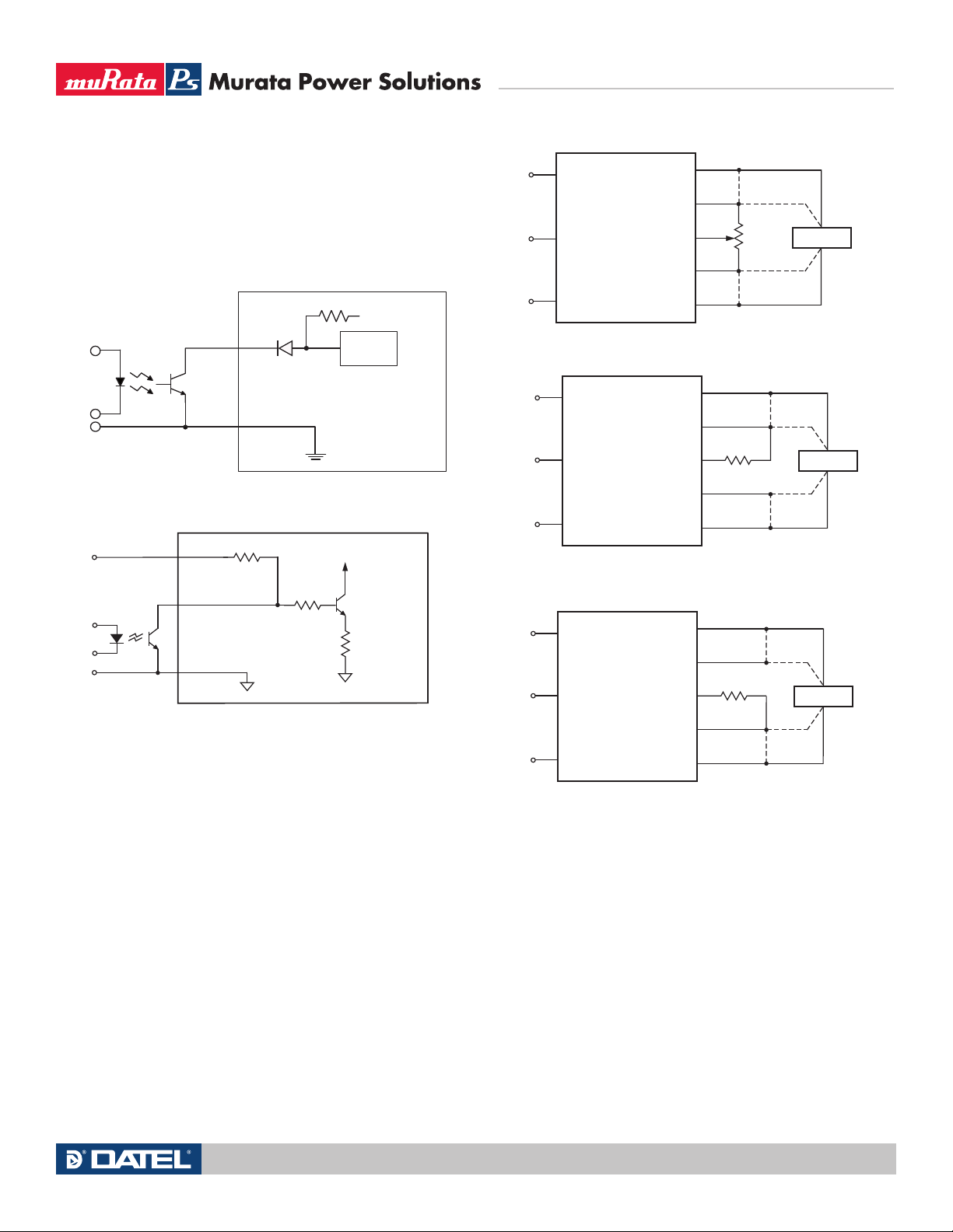
On/Off Control is left open or is pulled high, as per Figure 4. Positive-polarity
devices are disabled when the On/Off Control is pulled low.
Negative-polarity devices (“N” suffix) are off when the On/Off Control is open
(or pulled high), and on when the On/Off Control is pulled low with respect to
–Vin as shown in Figure 5.
Figure 4. Driving the Positive Polarity On/Off Control Pin
UWE Series
Wide Input, Isolated
Eighth-Brick DC/DC Converters
Figure 6. Trim Connections Using A Trimpot
Figure 5. Driving the Negative Polarity On/Off Control Pin
Dynamic control of the remote on/off function is facilitated with a mechanical
relay or an open-collector/open-drain drive circuit (optically isolated if appropriate). The drive circuit should be able to sink appropriate current (see Performance
Specs) when activated and withstand appropriate voltage when deactivated.
Applying an external voltage to the On/Off Control when no input power is
applied to the converter can cause permanent damage to the converter.
Trimming Output Voltage
UWE converters have a trim capability that allows users to adjust the output
voltages. Adjustments to the output voltages can be accomplished via a trim pot
(Figure 6) or a single fixed resistor as shown in Figures 7 and 8. A single fixed
resistor can increase or decrease the output voltage depending on its connection. The resistor should be located close to the converter and have a TCR less
than 100ppm/°C to minimize sensitivity to changes in temperature. If the trim
function is not used, leave the trim pin floating.
Figure 7. Trim Connections To Increase Output Voltages Using a Fixed Resistor
Figure 8. Trim Connections To Decrease Output Voltages
A single resistor connected from the Trim to the +Output, or +Sense where
applicable, will increase the output voltage in this configuration. A resistor connected from the Trim to the –Output, or –Sense where applicable, will decrease
the output voltage in this configuration.
Trim adjustments greater than the specified range can have an adverse
affect on the converter's performance and are not recommended. Excessive
voltage differences between VOUT and Sense, in conjunction with trim adjustment of the output voltage, can cause the overvoltage protection circuitry to
activate (see Performance Specifications for overvoltage limits). Power derating
is based on maximum output current and voltage at the converter’s output
pins. Use of trim and sense functions can cause output voltages to increase,
thereby increasing output power beyond the converter's specified rating or
cause output voltages to climb into the output overvoltage region. Therefore:
(VOUT at pins) x (IOUT) <= rated output power
Technical enquiries email: [email protected], tel: +1 508 339 3000www.murata-ps.com
MDC_UWE Series.A06 Page 9 of 12
Page 10
Note: Resistor values are in kΩ. Adjustment accuracy is subject to resistor
UP
VO – 3.3
R
T (k) =
–10.2
13.3(VO – 1.226)
3.3 – V
O
RT (k) =
–10.2
16.31
DOWN
3.3 Volt Output
UP
VO – 5
R
T (k) =
–10.2
20.4(VO – 1.226)
5 – V
O
RT (k) =
–10.2
25.01
DOWN
5 Volt Output
UP
VO – 12
R
T (k) =
–10.2
49.6(VO – 1.226)
UP
VO – 24
R
T (k) =
–10.2
101(VO – 1.226)
12 – V
O
RT (k) =
–10.2
60.45
DOWN
24 – VO
RT (k) =
–10.2
124.2
DOWN
12 Volt Output
24 Volt Output
Trim Equations
Trim Up Trim Down
LOAD
+OUTPUT
–INPUT
Sense Current
Contact and PCB resistance
losses due to IR drops
Contact and PCB resistance
losses due to IR drops
Sense Return
+INPUT
ON/OFF
CONTROL
TRIM
+SENSE
–OUTPUT
–SENSE
I
OUT Return
I
OUT
tolerances and factory-adjusted output accuracy. VO = desired output voltage.
UWE Series
Wide Input, Isolated
Eighth-Brick DC/DC Converters
Remote Sense Note: The Sense and VOUT lines are internally connected
through low value resistors. Nevertheless, if the sense function is not used for
remote regulation the user should connect the +Sense to +VOUT and –Sense to
–VOUT at the DC/DC converter pins.
UWE series converters have a sense feature to provide point of use regulation, thereby overcoming moderate IR drops in pcb conductors or cabling.
The remote sense lines carry very little current and therefore require minimal
cross-sectional-area conductors. The sense lines are used by the feedback
control-loop to regulate the output. As such, they are not low impedance points
and must be treated with care in layouts and cabling. Sense lines on a pcb
should be run adjacent to dc signals, preferably ground. In cables and discrete
wiring applications, twisted pair or other techniques should be implemented.
UWE series converters will compensate for drops between the output voltage at the DC/DC and the sense voltage at the DC/DC provided that:
[VOUT(+) –VOUT(–)] –[Sense(+) –Sense (–)] ≤ 5% VOUT
Output overvoltage protection is monitored at the output voltage pin, not
the Sense pin. Therefore, excessive voltage differences between VOUT and
Sense in conjunction with trim adjustment of the output voltage can cause the
overvoltage protection circuitry to activate (see Performance Specifications
for overvoltage limits). Power derating is based on maximum output current
and voltage at the converter’s output pins. Use of trim and sense functions can
cause output voltages to increase thereby increasing output power beyond the
UWE’s specified rating or cause output voltages to climb into the output overvoltage region. Also, the use of Trim Up and Sense combined may not exceed
+10% of VOUT. Therefore, the designer must ensure:
(VOUT at pins) x (IOUT) ≤ rated output power
Figure 9. Remote Sense Circuit Configuration
Technical enquiries email: [email protected], tel: +1 508 339 3000www.murata-ps.com
MDC_UWE Series.A06 Page 10 of 12
Page 11
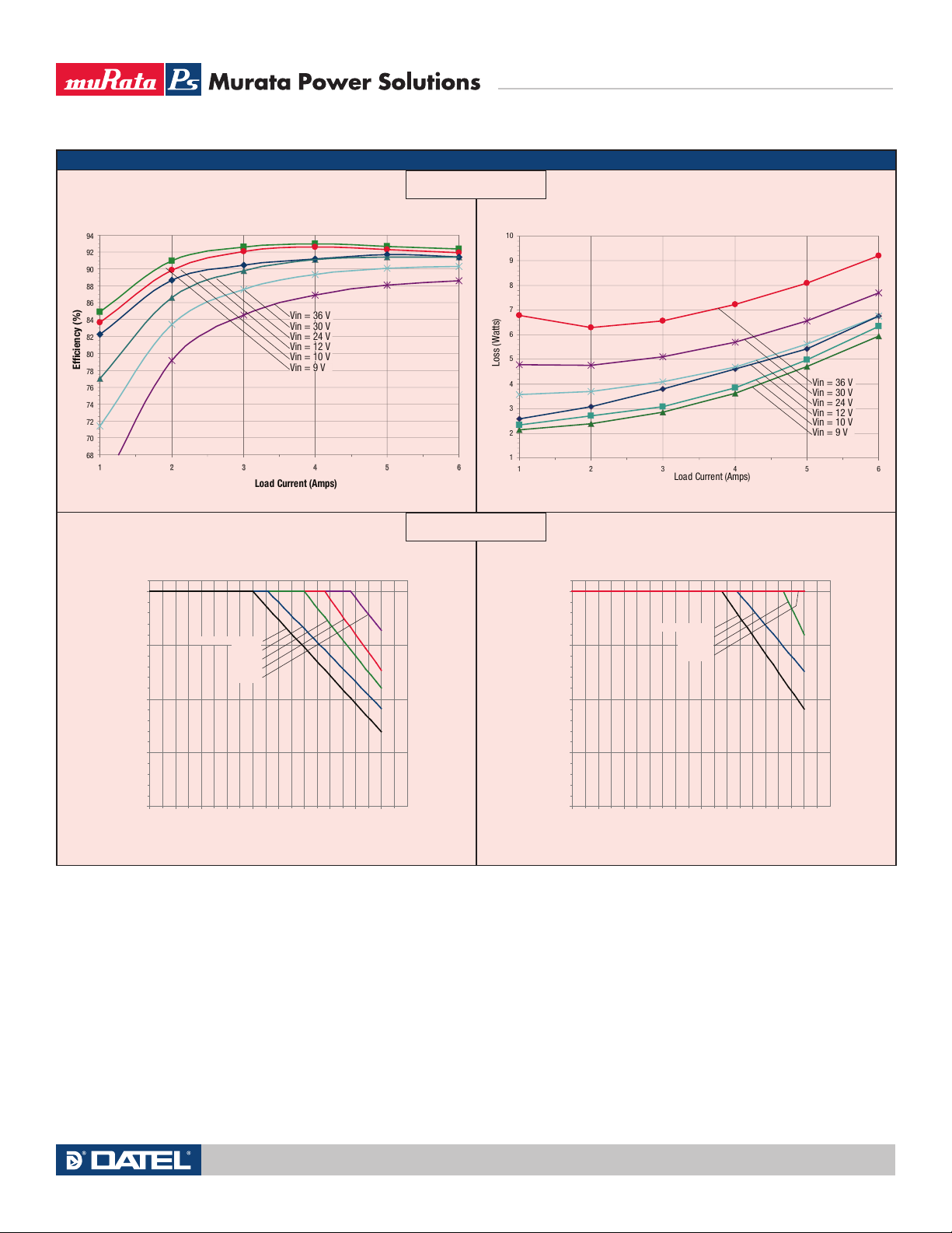
PERFORMANCE DATA
1 2 3 4 5 6
68
70
72
74
76
78
80
82
84
86
88
90
92
94
Load Current (Amps)
Efficiency (%)
Vin = 24 V
Vin = 30 V
Vin = 10 V
Vin = 12 V
Vin = 36 V
Vin = 9 V
Load Curre nt (Amps)
Loss (Watts)
1
2
3
4
5
6
7
8
9
10
1 2 3 4 5 6
Vin = 24 V
Vin = 30 V
Vin = 10 V
Vin = 12 V
Vin = 36 V
Vin = 9 V
4.0
4.5
5.0
5.5
6.0
40 45 50 55 60 65 70 75 80 85 90
Ambient Temperature (°C)
Output Current (Amps)
Natural Convection
100 LFM
200 LFM
300 LFM
400 LFM
4.0
4.5
5.0
5.5
6.0
40 45 50 55 60 65 70 75 80 85 90
Ambient Temperature (°C)
Output Current (Amps)
Natural Convection
100 LFM
200 LFM
300+ LFM
Efficiency vs. Line Voltage and Load Current @ 25°C Power Dissipation vs. Load Current @ 25°C
UWE Series
Wide Input, Isolated
Eighth-Brick DC/DC Converters
UWE-12/6-Q12N
Maximum Current Temperature Derating @ sea level
(Vin = 12V, transverse airflow, no baseplate)
UWE-12/6-Q12N
Maximum Current Temperature Derating @sea level
(Vin = 12V, transverse airflow, with baseplate)
Technical enquiries email: [email protected], tel: +1 508 339 3000www.murata-ps.com
MDC_UWE Series.A06 Page 11 of 12
Page 12
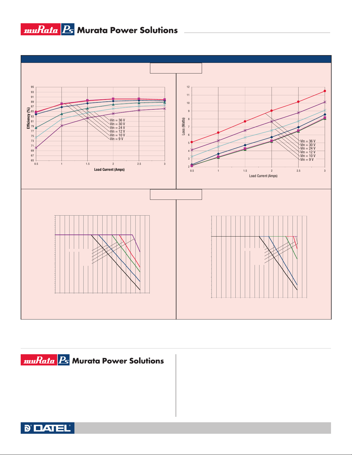
PERFORMANCE DATA
Load Curre nt (Amps)
Efficiency (%)
65
67
69
71
73
75
77
79
81
83
85
87
89
91
93
95
0.5 1 1.5 2 2 .5 3
Vin = 24 V
Vin = 30 V
Vin = 10 V
Vin = 12 V
Vin = 36 V
Vin = 9 V
2
3
4
5
6
7
8
9
10
11
12
0.5 1 1.5 2 2.5 3
Load Curre nt (Amps)
Loss (Watts)
Vin = 24 V
Vin = 30 V
Vin = 10 V
Vin = 12 V
Vin = 36 V
Vin = 9 V
2.40
2.50
2.60
2.70
2.80
2.90
3.00
3.10
3.20
40 4 5 50 5 5 60 65 70 75 80 85 9 0
Ambient Temperature (°C)
Output Current (Amps)
Natural Convection
100 LFM
200 LFM
300 LFM
400 LFM
2.40
2.60
2.80
3.00
3.20
40 45 50 55 60 6 5 70 7 5 8 0 85 9 0
Ambient Temperature (°C)
Output Current (Amps)
Natural Convection
100 LFM
200 LFM
300 LFM
400 LFM
Efficiency vs. Line Voltage and Load Current @ 25°C Power Dissipation vs. Load Current @ 25°C
UWE Series
Wide Input, Isolated
Eighth-Brick DC/DC Converters
UWE-24/3-Q12P
Maximum Current Temperature Derating @ sea level
(Vin = 12V, transverse airflow, no baseplate)
Murata Power Solutions, Inc.
11 Cabot Boulevard, Mansfield, MA 02048-1151 U.S.A.
Tel: (508) 339-3000 (800) 233-2765 Fax: (508) 339-6356
www.murata-ps.com email: [email protected] ISO 9001 REGISTERED
Murata Power Solutions, Inc. makes no representation that the use of its products in the circuits described herein, or the use of other
technical information contained herein, will not infringe upon existing or future patent rights. The descriptions contained herein do not imply
the granting of licenses to make, use, or sell equipment constructed in accordance therewith. Specifications are subject to change without
notice. © 2008 Murata Power Solutions, Inc.
UWE-24/3-Q12P
USA: Mansfield (MA), Tel: (508) 339-3000, email: [email protected]
Canada: Toronto, Tel: (866) 740-1232, email: [email protected]
UK: Milton Keynes, Tel: +44 (0)1908 615232, email: [email protected]
France: Montigny Le Bretonneux, Tel: +33 (0)1 34 60 01 01, email: [email protected]
Germany: München, Tel: +49 (0)89-544334-0, email: [email protected]
Japan: Tokyo, Tel: 3-3779-1031, email: [email protected]
08/26/08
China: Shanghai, Tel: +86 215 027 3678, email: [email protected]
Singapore: Parkway Centre, Tel: +65 6348 9096, email: [email protected]
Maximum Current Temperature Derating @sea level
(Vin = 12V, transverse airflow, with baseplate)
Osaka, Tel: 6-6354-2025, email: [email protected]
Guangzhou, Tel: +86 208 221 8066, email: [email protected]
Technical enquiries email: [email protected], tel: +1 508 339 3000www.murata-ps.com
MDC_UWE Series.A06 Page 12 of 12
 Loading...