

Datasheet UWP-15-200-D5, UWP-15-200-D48, UWP-15-200-D12, UWP-12-250-D5, UWP-12-250-D48 Datasheet (DATEL)
...Page 1
DATEL, Inc., Mansfield, MA 02048 (USA) • Tel: (508)339-3000, (800)233-2765 Fax: (508)339-6356 • Email: sales@datel.com • Internet: www.datel.com
Single Output
UWP Models
Features
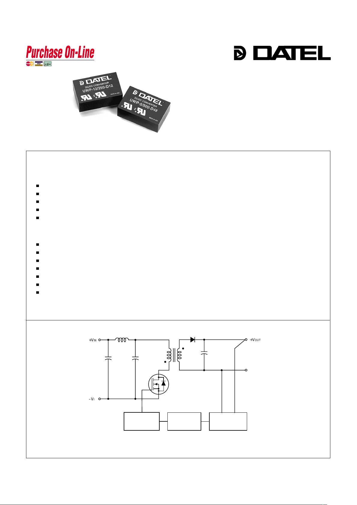
Figure 1. Simplified Schematic
DIP-Packaged, Standard-Pinout
3 Watt, DC/DC Converters
The proven cost-effectiveness, quality and long-term reliability that has come
to define DATEL’s standard, 3W, single-output, DIP-packaged DC/DC converters
(see UST 3W Models) is now available in the "other standard pinout" (see next
page) made popular by off-shore suppliers. These newly designed UWP Models
exploit totally automated SMT assembly techniques and do not contain any
trimpots, "wet" aluminum electrolytic capacitors, or manually soldered "flying"
leads. Their made-in-the-USA quality and affordable pricing are rapidly making
them the converters of choice in many existing applications.
UWP DC/DC converters bring true component-like convenience to designers
of modern distributed power systems. Exploiting an efficient, high-frequency
(170-200kHz), flyback topology and high-density SMT assembly techniques,
UWP DC/DC’s have enough space to include input (pi type) and output filters
within their package. They are fully isolated (500Vdc guaranteed) and do not
require any external components to meet published specifications. They operate,
without derating, over the full –40 to +75°C temperature range.
Output voltages are either 5, 12 or 15 Volts. Input voltage ranges are either
4.5-9V ("D5" models), 9-18V ("D12" models) or an ultra-wide 18-72V ("D48"
models). Output transient response time is a quick 200µsec, and output ripple
and noise are typically 75mVp-p. All models are certified to UL1950, CSA 22.2
No. 950 and IEC950. Full EMI/EMC characterizations are currently in progress.
DATEL’s UWP Model 3W DC/DC’s are ideal replacements for other more
costly, less reliable power converters as well as excellent choices for new
design-ins in systems demanding small size, low cost and high reliability .
■
n
n
n
n
n
n
n
n
n
n
n
n
+V
OUT
+V
IN
–V
IN
PWM
CONTROLLER
OPTO
ISOLATION
REFERENCE &
ERROR AMP
COMMON
Low cost! High quality!
Highly reliable, 100% SMT construction
Standard DIP package and pinout
No external components required
5, 12 or 15 Volt outputs
Choice of 3 wide input ranges:
4.5-9 Volts
9-18 Volts
18-72 Volts
Guaranteed efficiencies to 73%
Fully isolated, 500Vdc guaranteed
Internal input/output filtering
Output current limiting
–40 to +75°C operation with no derating
UL1950/C22.2 No. 950/IEC950 certified
Modifications and customs for OEM’s
INNOVATION and EX C ELL E N C E
®
®
www.datel.co
m
Page 2
XW P Series
3W, SINGLE OUTPUT DC/DC CONVERTERS
UWP-5/500-D5 5 500 75 120 ±0.2% ±0.5% 5 4.5-9 18/676 72% 74% C1A, P19
UWP-5/500-D12 5 500 75 120 ±0.2% ±0.5% 12 9-18 25/278 71% 75% C1A, P19
UWP-5/500-D48 5 500 75 120 ±0.2% ±0.5% 48 18-72 7/69 71% 75% C1A, P19
UWP-12/250-D5 12 250 75 150 ±0.5% ±0.5% 5 4.5-9 30/800 73% 75% C1A, P19
UWP-12/250-D12 12 250 75 150 ±0.5% ±0.5% 12 9-18 25/338 72% 74% C1A, P19
UWP-12/250-D48 12 250 75 150 ±0.5% ±0.5% 48 18-72 8/81 73% 77% C1A, P19
UWP-15/200-D5 15 200 75 150 ±0.5% ±0.5% 5 4.5-9 30/800 73% 75% C1A, P19
UWP-15/200-D12 15 200 75 150 ±0.5% ±0.5% 12 9-18 25/338 72% 74% C1A, P19
UWP-15/200-D48 15 200 75 150 ±0.5% ±0.5% 48 18-72 8/81 73% 77% C1A, P19
2
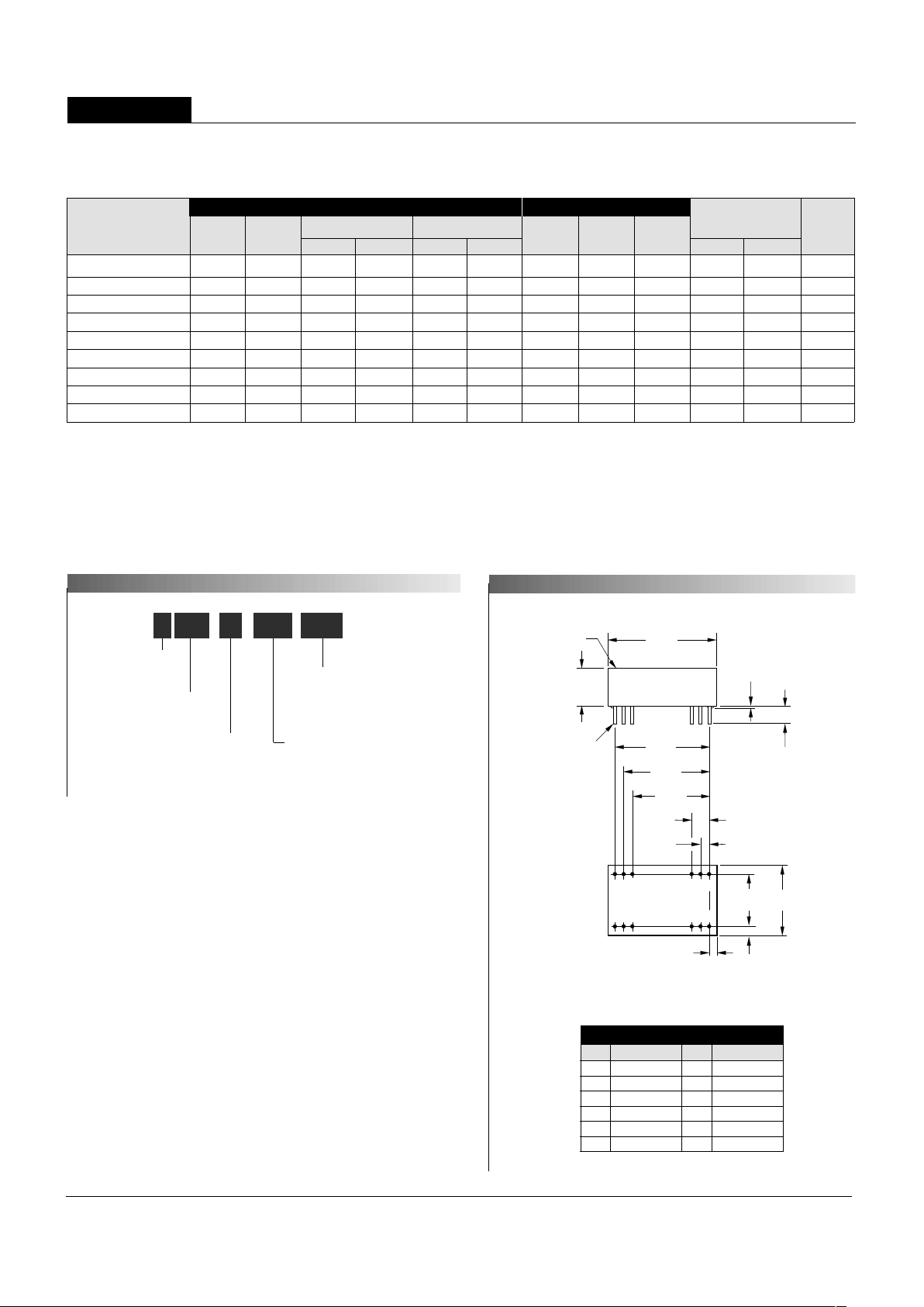
PART NUMBER STRUCTURE
MECHANICAL SPECIFICATIONS
I/O Connections
Performance Specifications and Ordering Guide
R/N (mVp-p)
➁
Load
VOUT
(Volts)
Output
Package
(Case,
Pinout)
Efficiency
Regulation (Max.)
➂
Line
VIN Nom.
(Volts)
Range
(Volts)Model
Input
IIN ➃
(mA)
➀
Max.
Typ.
Typ.
Min.
IOUT
(mA, Max.)
➀
Typical at TA = +25°C under nominal line voltage and full-load conditions unless otherwise noted.
➁
Ripple/Noise (R/N) measured over a 20MHz bandwidth.
➂
10% to 100% load.
➃
Nominal line voltage, no-load/full-load conditions.
1.25
(31.75)
0.15 MIN
(3.81)
0.200
(5.08)
STANDOFFS
0.025
(0.64)
0.020 ±0.002 DIA.
(0.508 ±0.051)
0.45
(11.43)
0.10
(2.54)
0.80
(20.32)
0.600
(15.24)
0.08
(2.03)
0.100
(2.54)
0.900
(22.86)
1.000
(25.40)
1.100
(27.94)
1
23
10
11 12
242322 151413
PIN 1
INDICATOR
BOTTOM VIEW
PLASTIC CASE WITH AN INSULATED BASE
Input Voltage Range:
D5 = 4.5-9 Volts (5V nominal)
D12 = 9-18 Volts (12V nominal)
D48 = 18-72 Volts (48V nominal)
Nominal Output Voltage:
5, 12 or 15 Volts
Maximum Output Current
in mA
Wide Range Input
Alternate pinout
Output Configuration:
U = Unipolar
5U WP 500 D48-/
-
Pin Function P19 Pin Function P19
1 +Input 13 –Input
2 N.C. 14 +Output
3 N.C. 15 –Output
10 –Output 22 N.C.
11 +Output 23 N.C.
12 –Input 24 +Input
Case C1A
Page 3

UWP Models
3W, SINGLE OUTPUT DC/DC CONVERTERS
3
Input Voltage:
"D5" Models 12 Volts
"D12" Models 20 Volts
"D48" Models 80 Volts
Input Reverse-Polarity Protection Current must be <2A. Brief duration
only. Fusing recommended.
Output Overvoltage Protection None
Output Current Current limited. Max. current and
short-circuit duration are model
dependent. "D12" and "D48" models
can withstand sustained output short
circuits.
Storage Temperature –40 to +100°C
Lead Temperature (soldering, 10 sec.) +300°C
Floating Outputs
Since these are isolated DC/DC converters, their outputs are "floating."
Users may ground either the negative side (–Output, pins 10 and 15) for
normal usage or the positive side (+Output, pins 11 and 14) to effectively
reverse the output polarity.
Filtering and Noise Reduction
All UWP 3 Watt DC/DC Converters achieve their rated ripple and noise
specifications without the use of external input/output capacitors. In critical
applications, input/output ripple and noise may be further reduced by
installing electrolytic capacitors across the input terminals and/or low-ESR
tantalum or electrolytic capacitors across the output terminals. The caps
should be located as close to the power converters as possible. Typical
values are listed in the tables below. In many applications, using values
greater than those listed will yield better results.
To Reduce Input Ripple
"D5" Models 47µF, 15V
"D12" Models 10µF, 35V
"D48" Models 4.7µF, 100V
To Reduce Output Ripple
5V Outputs 47µF, 10V, Low ESR
12/15V Outputs 22µF, 20V, Low ESR
In critical, space-sensitive applications, DATEL may be able to tailor the
internal input/output filtering of these units to meet your specific requirements. Contact our Applications Engineering Group for additional details.
These are stress ratings. Exposure of devices to any of these conditions may adversely
affect long-term reliability. Proper operation under conditions other than those listed in the
Performance/Functional Specifications Table is not implied.
Absolute Maximum Ratings
TECHNICAL NOTES
Performance/Functional Specifications
Typical @ TA = +25°C under nominal line voltage and full-load conditions, unless noted.
➀
Input
Input Voltage Range:
"D5" Models 4.5-9 Volts (5V nominal)
"D12" Models 9-18 Volts (12V nominal)
"D48" Models 18-72 Volts (48V nominal)
Input Current See Ordering Guide
Input Filter Type
➁
Pi
Reverse-Polarity Protection Y es (Instantaneous, 2A maximum)
Output
VOUT Accuracy (50% load) ±1%, maximum
Temperature Coefficient ±0.02% per °C
Ripple/Noise (20MHz BW)
➁
See Ordering Guide
Line/Load Regulation See Ordering Guide
Efficiency See Ordering Guide
Isolation Voltage
➂
500Vdc, minimum
Current Limiting:
"D5" Models Power-limiting technique, auto-recovery
"D12" and "D48" Models Hiccup technique, auto-recovery
Dynamic Characteristics
Transient Response (50% load step) 200µsec to ±1.5% of final value
Switching Frequency:
"D48" Models 200kHz
"D5" and "D12" Models 170kHz
Environmental
Operating Temperature
(Ambient, no derating) –40 to +75°C
Storage Temperature –40 to +100°C
Physical
Dimensions 1.25" x 0.8" x 0.45" (31.8 x 20.3 x 11.4mm)
Case Material Diallyl phthalate, UL94V-0-rated
Pin Material Brass, solder coated
Weight 0.5 ounces (14.2 grams)
➀
These power converters require a minimum 10% loading to maintain specified regulation.
Operation under no-load conditions will not damage these devices; however
they may not meet all listed specifications.
➁
Application-specific internal input/output filtering can be recommended and perhaps added
internally upon request. Contact DATEL Applications Engineering for details.
➂
Devices can be screened or modified for higher guaranteed isolation voltages.
Contact DATEL Applications Engineering for details or see DATEL's UST 3W DC/DC's
for guaranteed 1000Vdc isolation.
Page 4

XW P Series
3W, SINGLE OUTPUT DC/DC CONVERTERS
Input Fusing
Certain applications and/or safety agencies may require the installation of
fuses at the inputs of power conversion components. For DATEL UWP 3
Watt DC/DC Converters, you should use slow-blow type fuses with values
no greater than the following:
V
IN Range Fuse Value
"D5" 1.5A
"D12" 1A
"D48" 0.5A
DATEL makes no representation that the use of its products in the circuits described herein, or the use of other technical information contained herein, will not infringe upon existing or future patent rights. The descriptions contained herein
do not imply the granting of licenses to make, use, or sell equipment constructed in accordance therewith. Specifications are subject to change without notice. The DATEL logo is a registered DATEL, Inc. trademark.
DATEL (UK) LTD. Tadley, England Tel: (01256)-880444
DATEL S.A.R.L. Montigny Le Bretonneux, France Tel: 01-34-60-01-01
DATEL GmbH München, Germany Tel: 89-544334-0
DATEL KK Tokyo, Japan Tel: 3-3779-1031, Osaka Tel: 6-354-2025
DATEL, Inc. 11 Cabot Boulevard, Mansfield, MA 02048-1151
Tel: (508) 339-3000 (800) 233-2765 Fax: (508) 339-6356
Internet: www.datel.com Email: sales@datel.com
Data Sheet Fax Back:(508) 261-2857
DS-0405 8/99
INNOVATION and EX C ELL E N C
E
®
®
DATEL’s world-class design, development and manufacturing team stands
ready to work with you to deliver the exact power converter you need for
your demanding, large volume, OEM applications. And ... we’ll do it on time
and within budget!
Our experienced applications and design staffs; quick-turn prototype
capability; highly automated, SMT assembly facilities; and in-line SPC
quality-control techniques combine to give us the unique ability to design
and deliver any quantity of power converters to the highest standards of
quality and reliability.
We have compiled a large library of DC/DC designs that are currently used
in a variety of telecom, medical, computer, railway, aerospace and industrial
applications. We may already have the converter you need.
Contact us. Our goal is to provide you the highest-quality, most costeffective power converters available.
CUSTOM CAPABILITIES
ISO 9001 REGISTERED
80
70
60
50
40
30
20
10
0
10
20
Frequency (M Hz)
100
1000
FCC Class B Limit
U W P-15/200-D 5 R adiated E m issio ns
FC C P art 15 C lass B , 3 M eters
Converter O utput = +15Vdc @ +180m A
R a d ia t e d E m is s io n s (d B µ V /M )
R adiated E m issions
U W P-15/200-D 5 R adiated E m issions
EN 55022 C lass B , 10 M eters
Converter O utput = +15Vdc @ +180m A
80
70
60
50
40
30
20
10
0
10
20
Frequency (M Hz)
100
1000
R adiated E m issions
EN 55022 Class B Lim it
R a d ia t e d E m is s io n s (d B µ V /M )
If you’re designing with EMC in mind, please note that all of DATEL’s
UWP 3 Watt DC/DC Converters have been characterized for radiated and
conducted emissions in our new EMI/EMC laboratory. Testing is conducted
in an EMCO 5305 GTEM test cell utilizing EMCO automated EMC test
software. Radiated emissions are tested to the limits of FCC Part 15, Class
B and CISPR 22 (EN 55022), Class B. Correlation to other specifications
can be supplied upon request. Radiated emissions plots to FCC and CISPR
22 for model UWP-15/200-D5 appear below. Published EMC test reports are
available for each model number. Contact DATEL’s Applications Engineering
Department for more details.
EMI RADIATED EMISSIONS
 Loading...