

Page 1
DATA SHEET
MOS INTEGRATED CIRCUIT
µ
PD17P068
4-BIT SINGLE-CHIP MICROCONTROLLER
WITH ON-CHIP HARDWARE FOR TV SYSTEMS
The µPD17P068 is a one-time PROM version of the µPD17068 that has on-chip mask ROM.
The µPD17P068, which can be programmed only once, is suited for testing during development of µPD17068
systems and limited production runs.
µ
Use this data sheet together with
µ
PD17P068 does not provide a level of reliability intended for mass production of the customer's
The
products. Use it only for functional evaluation when experimenting or doing product trial tests.
PD17068 documents.
FEATURES
• Compatible with the
µ
PD17068
• One-time PROM : 12160 × 16 bits
• Operating voltage : VDD = 5 V ± 10 %
ORDERING INFORMATION
Part Number Package
µ
PD17P068GF-3BA 100-pin plastic QFP (14 × 20mm)
Document No. U10336EJ1V0DS00
Date Published November 1995 P
Printed in Japan
The information in this document is subject to change without notice.
©
1995
Page 2

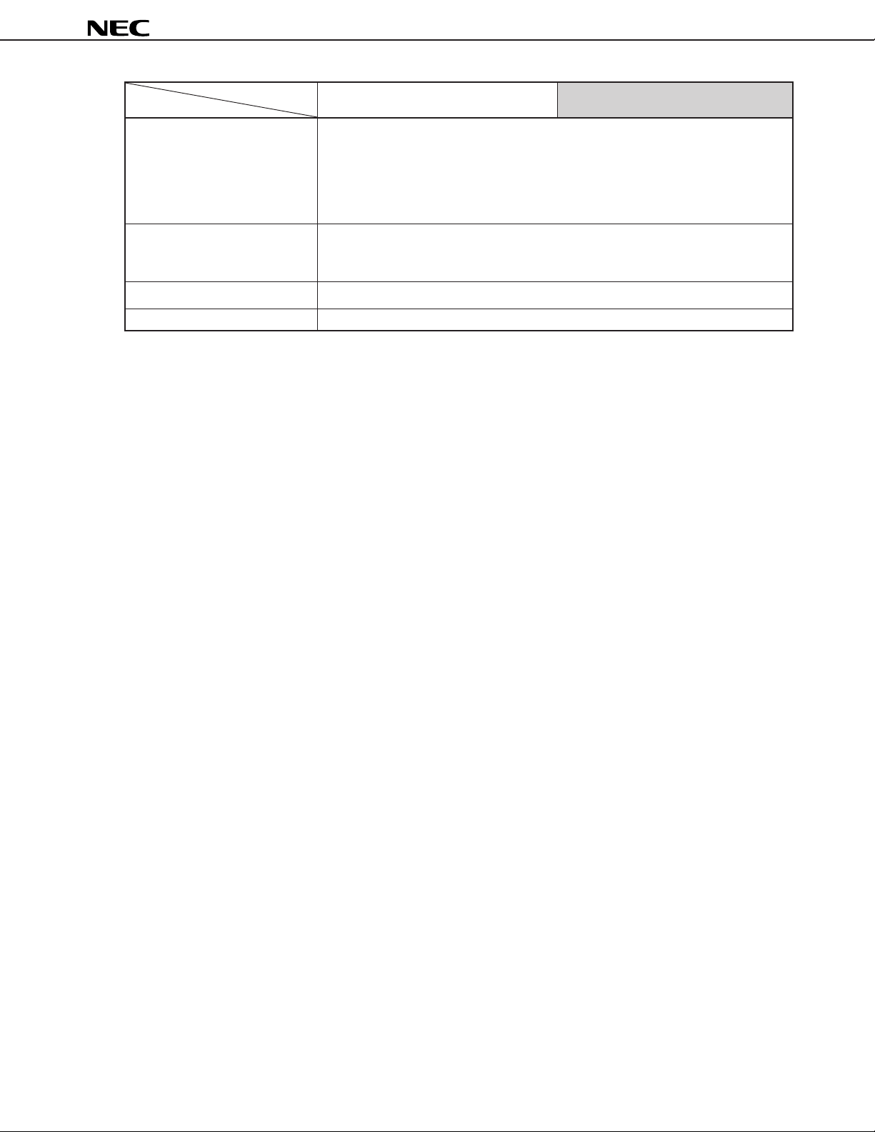
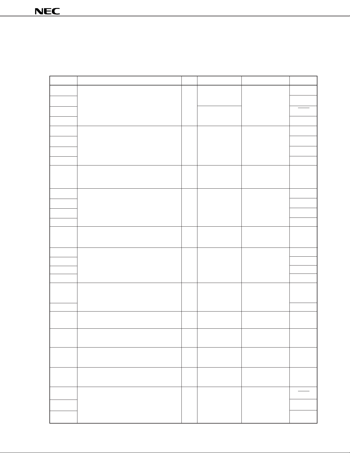
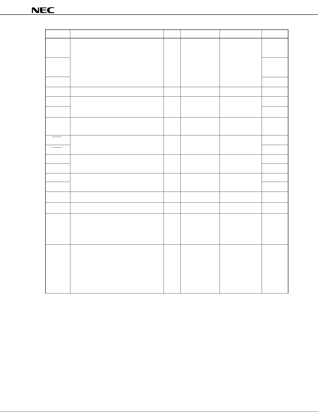
FUNCTIONAL OUTLINE
µ
PD17P068
Part Number
Item
Program memory (ROM) • 12160 × 16 bits
Table reference area: 12160 × 16 bits
Character ROM (CROM) • 6144 × 16 bits
Data memory (RAM)
Video RAM (VRAM) • 672 × 4 bits (also used as data memory (RAM))
System register • 12 × 4 bits
Register file • 12 × 4 bits
General port register • 12 × 4 bits
Instruction execution time • 2 µs (when using 8-MHz crystal resonator)
Stack levels • 12 levels (stack manipulation possible)
General ports • Input ports : 4
IDC
(Image Display Controller)
• 1007 × 4 bits (including area serving also as VRAM)
Data buffer: 4 × 4 bits, general register: 16 × 4 bits
• I/O ports : 19
• Output ports : 21
• Number of displayable characters : 192 characters max. per screen
• Display format : 16 × 16-dot mode 15 lines × 24 columns
• Character types : 255 types (user programmable)
• Character format : 16 × 16 dots and 14 × 16 dots selectable
• Color : 15 colors
• Character size : Vertical : 16 sizes (specifiable for
µ
PD17068
Mask ROM One-time PROM
(up to 350 characters with program)
: 14 × 16-dot mode 17 lines × 24 columns
(2 dots can be placed between
characters)
Horizontal : 24 sizes (specifiable for
µ
PD17P068
each line)
each character)
• 2 systems
Serial interface Serial interface 0 (compatible with 2-wire system, 3-wire system and I2C Bus)
Serial interface 1 (3-wire system)
D/A converter • 8 bits × 9 channels (PWM output, 12.5 V max.)
A/D converter • 6 bits × 8 channels (successive approximation by software)
• 10 channels (maskable interrupt)
Interrupt External interrupt : 3 channels (INT0, INTNC, VSYNC, HSYNC)
Internal interrupt : 7 channels (timer 0, 1, serial interface 0, 1, basic timer 2,
VRAM pointer, timer 0 overflow)
2
Page 3
µ
PD17P068
Part Number
Item
Timer 0 : 10 µs to 204.75 ms (interrupt)
Timer 1 : 1 µs to 256 ms (interrupt)
Timer
Reset • Reset with CE pin (CE pin: Low level → High level)
Supply voltage VDD = 5 V ± 10 %
Package 100-pin plastic QFP (14 × 20 mm)
Basic timer 0 : 1, 5, 100 ms (carry)
Basic timer 1 : 125 µs, 1 ms, 5 ms, 100 ms, external (carry)
Basic timer 2 : 125 µs, 1 ms, 5 ms, 100 ms, external (interrupt)
Watch timer : Date, Hour, Minute, Second (counter)
• Power-on reset
• Power interruption detection
µ
PD17068
µ
PD17P068
3
Page 4

BLOCK DIAGRAM
VCO
PSC
EO
IN
OSC
OSC
OUT
H
SYNC
V
SYNC
RED
GREEN
BLUE
BLANK
2
)
I (P0B
3
HSCNT (P0B
)
PLL
OSC
Circuit
IDC
Hsync
Counter
RAM
×
1007 4 bits
VRAM
×
(672 4 bits)
SYSTEM REG.
RF
ALU
A/D
Converter
D/A
Converter
OSC
Watch
Timer
µ
PD17P068
ADC
0
ADC1(P0D0/MD0/XT
ADC
2
(P0D1/MD1/XTIN)
3
(P0D2/MD2)
ADC
4
(P0D3/MD3)
ADC
5
(P1C0/D0)
ADC
7
(P1C2/D2)
ADC
PWM0(P2C0)
PWM
3
(P2C3)
PWM
4
(P2B0)
PWM
7
(P2B3)
8
(P2A0)
PWM
XTIN(P0D1/ADC2)
XT
OUT
(P0D0/ADC1)
1
CKOUT (P1B
)
OUT
)
0
-P0A
P0A
P0B0-P0B
P0C0-P0C
P0D0-P0D
P1A0-P1A
P1B0-P1B
4-D7
(D
P1C0-P1C
P1D0-P1D
P2A
P2B0-P2B
P2C0-P2C
P2D0-P2D
XIN/CLK
X
)
OUT
4
3
4
3
3
4
4
3
3
4
4
3
Instruction
Decoder
One-time PROM
×
12160 16 bits
CROM
×
6144 16 bits
Program Counter
Port
3
4
4
3
0
Stack
×
12 14 bits
Timer0
Timer1
Basic
Timer0
Basic
Timer1
Basic
Timer2
TMIN (P1B3)
SDA (P0A0)
3
4
4
3
2
3
Main
Oscillator
CPU
Peripheral
Serial
I/O0
Serial
I/O1
SCL (P0A1)
0
(P0A2)
SCK
SO
0
(P0A3)
SI
0
(P0B0)
SCK1(P2D0)
SO1(P2D1)
SI1(P2D2)
STP
/P1B
RLS
GND0, GND
4
V
CE
DD
2
1
Reset
Interrupt
INTNC(VPP)
INT
0
Page 5

PIN CONFIGURATION (Top View)
(1) Normal operation mode
P1D3CEPSCEOGND2GND1NCNCNCNC
100
99 98 97 96 95 94 93 92 91 90 89 88 87 86 85 84 83 82 81
31 32 33 34 35 36 37 38 39 40 41 42 43 44 45 46 47 48 49 50
3/TMIN
P1B
P1B
2 /RLS STP
P1B
1/CKOUT
0 /PWM8
P2A
P2D
P2D 1 /SO1
P2D 0 /SCK1
OSCOUT
OSCIN
P1D2
P1D1
P1D0
INT0
NC
NC
P1B
NC
NC
P1A
P1A2
NC
NC
NC
P1A
P1A0
NC
NC
NC
2/SI1
NC
GND0
1
2
3
4
5
6
7
8
9
0
10
11
12
3
13
14
15
16
17
1
18
19
20
21
22
23
24
25
26
27
28
29
30
VCO
DD1
NC
DD0
V
V
XIN
NC
µ
PD17P068GF-3BA
XOUT
µ
PD17P068
INT NC
XTOUT/ADC1 /P0D0
XTIN /ADC 2/P0D1
80
79
78
77
76
75
74
73
72
71
70
69
68
67
66
65
64
63
62
61
60
59
58
57
56
55
54
53
52
51
P0D2 /ADC3
P0D3 /ADC4
P1C0 /ADC5
P1C1 /ADC6
NC
2/ADC7
P1C
P1C3
NC
ADC
0
NC
P0C0
NC
1
P0C
NC
P0C
2
NC
P0C3
NC
P2C
0/PWM0
NC
1/PWM1
P2C
NC
2/PWM2
P2C
NC
3/PWM3
P2C
NC
P2B0 /PWM4
P2B1 /PWM5
P2B2 /PWM6
P2B3 /PWM7
RED
NC
GREEN
BLUE
BLANK
SYNC
H
NC
VSYNC
NC
P0B3 /HSCNT
NC
2/I
P0B
1
P0B
NC
NC
P0B0/SI0
P0A3/SO0
P0A1 /SCL
P0A2/SCK0
P0A0 /SDA
5
Page 6

(2) PROM programming mode
100
1
2
3
4
5
6
7
8
9
10
11
12
13
14
15
16
17
18
19
20
21
22
23
24
25
26
27
28
29
30
31 32 33 34 35 36 37 38 39 40 41 42 43 44 45 46 47 48 49 50
(OPEN)
(L)
(OPEN)
D
D
(OPEN)
D
D
(OPEN)
(L)
(OPEN)
GND
(OPEN)
(L)
7
6
5
4
0
2
1
(L)
(OPEN)
(L)
(OPEN)
GND
GND
(OPEN)
DD1VDD0
V
CLK
(OPEN)
VPPMD0MD
99 98 97 96 95 94 93 92 91 90 89 88 87 86 85 84 83 82 81
µ
PD17P068GF-3BA
µ
PD17P068
1
MD
80
79
78
77
76
75
74
73
72
71
70
69
68
67
66
65
64
63
62
61
60
59
58
57
56
55
54
53
52
51
2
MD
3
D
0
D
1
(OPEN)
2
D
D
3
(OPEN)
(OPEN)
(L)
(L)
(OPEN)
(L)
(OPEN)
(L)
(OPEN)
(L)
(OPEN)
Caution Contents in parentheses indicate how to handle unused pins in PROM programming mode.
L: Connect to GND via a resistor (470 Ω) separately.
OPEN: Leave unconnected.
6
Page 7

µ
PD17P068
PIN IDENTIFICATIONS
ADC0-ADC7 : A/D converter input P1C0-P1C3 : Port 1C
BLANK : Blanking signal output P1D0-P1D3 : Port 1D
BLUE : Character signal output P2A0 : Port 2A
CE : Chip enable P2B
CKOUT : Watch timer adjustment P2C0-P2C3 : Port 2C
output P2D0-P2D2 : Port 2D
CLK : Address update clock input PSC : Pulse swallow control output
0-D7 : Data input/output PWM0-PWM8 : Pulse-width modulation output
D
EO : Error out RED : Character signal output
0-GND2 : Ground RLSSTP : Clock stop release signal input
GND
GREEN : Character signal output SCK0, SCK1 : Shift clock input/output
HSCNT : Horizontal synchronizing SCL : Shift clock input/output
signal counter input SDA : Serial data input/output
SYNC : Horizontal synchronizing Sl0, Sl1 : Serial data input
H
signal input SO0 , SO1:Serial data output
I : Character signal output TMIN : Event input of basic timer 1 or 2
0, INTNC : External interrupt request VCO : Local oscillation input
INT
signal input VDD0, VDD1 : Positive power supply
0-MD3 : Operation mode select VPP : Program voltage application
MD
NC : No connection VSYNC : Vertical synchronizing signal input
OSCIN, OSCOUT : LC oscillation for IDC XIN, XOUT : Main clock oscillation
0-P0A3 : Port 0A XTIN, XTOUT : Watch timer oscillation
P0A
P0B0-P0B3 : Port 0B
P0C0-P0C3 : Port 0C
0-P0D3 : Port 0D
P0D
P1A0-P1A3 : Port 1A
P1B0-P1B3 : Port 1B
0-P2B3 : Port 2B
7
Page 8

µ
PD17P068
CONTENTS
1. PIN FUNCTIONS ................................................................................................................................. 9
1.1 Normal Operation Mode ........................................................................................................................... 9
1.2 PROM Programming Mode .................................................................................................................... 13
1.3 Pin Equivalent Circuits .......................................................................................................................... 14
1.4 Handling of Unused Pins....................................................................................................................... 19
1.5 Notes on Using the CE and INTNC Pins (Only in Normal Operation Mode) ................................... 21
2. WRITE, READ, AND VERIFY OF ONE-TIME PROM (PROGRAM MEMORY)............................ 22
2.1 Operation Modes in Program Memory Write/Read/Verify................................................................. 23
2.2 PROM Write Procedure .......................................................................................................................... 24
2.3 PROM Read Procedure .......................................................................................................................... 25
3. ELECTRICAL SPECIFICATIONS .................................................................................................... 26
4. PACKAGE DRAWING ...................................................................................................................... 31
APPENDIX DEVELOPMENT TOOLS.................................................................................................... 32
8
Page 9
µ
PD17P068
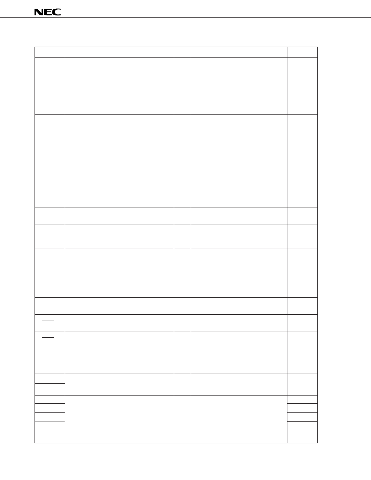
1. PIN FUNCTIONS
1.1 Normal Operation Mode
(1) Port pins
Pin Name Description I/O Output Type When Reset Shared by
P0A0 SDA
P0A1 SCL
P0A2 SCK0
P0A3 SO0
P0B0 Sl0
P0B1 —
P0B2 l
P0B3 HSCNT
P0C0
—
P0C3
P0D0 ADC1/XTOUT
P0D1 ADC2/XTIN
P0D2 ADC3
P0D3 ADC4
P1A0
—
P1A3
P1B0 —
P1B1 CKOUT
P1B2 RLSSTP
P1B3 TMIN
P1C0 ADC5
P1C2 ADC7
P1C3 —
P1D0
—
P1D3
P2A0 PWM8
P2B0 PWM4
P2B3 PWM7
4-bit I/O port.
These pins serve as a bit-selectable N-ch open drain
4-bit input/output port. All these pins
are set to input pins when power (VDD) I/O Input
is turned on, when clock is stopped, or
when reset signal is input to the CE pin.
4-bit I/O port.
These pins serve as a bit-selectable 4-bit
input/output port. All these pins are set to
input pins when power (VDD) is turned
on, when clock is stopped, or when reset
signal is input to the CE pin.
These pins serve as a 4-bit output port.
The output state of each pin is undefined O CMOS push-pull Undefined output
after power (VDD) is turned on.
These pins serve as a 4-bit input port. I — Input with pull-
These pins serve as a 4-bit output port. O Middle voltage, Undefined output
4-bit I/O port.
These pins serve as a bit-selectable 4-bit I/O CMOS push-pull Input
input/output port.
4-bit I/O port. These pins serve as 4-bit- I/O CMOS push-pull Input
selectable 4-bit I/O port.
These pins serve as a 4-bit output port. O CMOS push-pull Undefined output
This pin serves as a 1-bit output port. O Undefined output
These pins serve as a 4-bit output port. O Undefined output
CMOS push-pull
I/O CMOS push-pull Input
down resistor
N-ch open-drain
high current
N-ch open-drain
Middle voltage
N-ch open-drain
Middle voltage
P2C0 PWM0
P2C3 PWM3
P2D0 SCK1
P2D1 SO1
P2D2 Sl1
These pins serve as a 4-bit output port. O Undefined output
These pins serve as a bit-selectable 3-bit
input/output port. All these pins are set to
input pins when power (VDD) is turned on, I/O CMOS push-pull Input
when clock is stopped, or when reset
signal is input to the CE pin.
N-ch open-drain
Middle voltage
9
Page 10
µ
PD17P068
(2) Non-port pins
Pin Name Description I/O Output Type When Reset Shared by
This pin outputs signals from the charge
pump of the PLL frequency synthesizer.
If the frequency divided from the local
EO oscillator (VCO) frequency is higher (lower) O CMOS 3-state High-impedance —
than the reference frequency, high (low)
level is output from this pin, respectively.
When the two frequencies match, this pin
is placed in the high-impedance state.
This pin outputs pulse swallow control
PSC signal. This signal switches division ratio O CMOS push-pull Output —
for the dedicated prescaler µPB595.
This pin is the input of the local oscillator.
The output signal coming from the local
oscillator (VCO) in the tuner and divided by
VCO the dedicated prescaler µPB595 should be I — —
input to this pin, where the µPB595 is a
two-module prescaler capable of frequency
division up to 1 GHz.
Internally
pulled down
HSCNT I — Input P0B3
BLANK O CMOS push-pull Low level output —
RED data that correspond the R signal (one of O CMOS push-pull Low level output —
GREEN that correspond the G signal (one of the O CMOS push-pull Low level output —
BLUE that correspond the B signal (one of the O CMOS push-pull Low level output —
I O CMOS push-pull Input P0B2
HSYNC I — Input —
VSYNC I — Input —
OSCIN
OSCOUT
ADC0
ADC1
ADC2
ADC3
ADC4
ADC5
ADC7
This pin is the input of the H sync signal
counter.
This active-high pin outputs blanking
signals to delete video signals.
This active-high pin outputs character
the RGB signals of IDC).
This active-high pin outputs character data
RGB signals of IDC).
This active-high pin outputs character data
RGB signals of IDC).
This pin outputs character data that
correspond the I signal of IDC.
The H sync signals for IDC should be
input to this pin in an active-low manner.
The V sync signals for IDC should be input
to this pin in an active-low manner.
These are the input and output pins of the
LC oscillation circuit for IDC. Adjust the — — — —
oscillation frequency to 10 MHz.
These are the analog input pins of the
6-bit resolution A/D converter.
These are the analog input pins of the
6-bit resolution A/D converter.
I — Input
I — Input
P0D0/XTOUT
P0D1/XTIN
P0D2
P0D3
P1C0
P1C2
—
10
Page 11
µ
PD17P068
Pin Name Description I/O Output Type When Reset Shared by
PWM0 P2C0
PWM3 P2C3
PWM4 These are the output pins of the O N-ch open-drain P2B0
8-bit resolution D/A converter. Middle-voltage
PWM7 P2B3
PWM8 P2A0
TMIN This pin is the input of basic timer 1 or 2. I — Input P1B3
Low-level output
or high impedance
XTIN
XTOUT
CKOUT O CMOS push-pull Input P1B1
SCK0 P0A2
SCK1 P2D0
Sl0 P0B0
Sl1 P2D2
SO0 P0A3
SO1 P2D1
SCL These pins input and output shift clocks. I/O N-ch open-drain Input P0A1
SDA These pins input and output serial data. I/O N-ch open-drain Input P0A0
INT0 request is issued at the rising or falling I — Input —
INTNC commands from a remote control unit I — Input —
A 32.768-kHz crystal resonator for watch
timer operation should be connected to — — —
these pins.
This pin outputs the signal to control the
watch timer.
These pins input and output shift clocks. I/O CMOS push-pull Input
These pins input serial data. I — Input
These pins output serial data. O CMOS push-pull Input
This pin inputs interrupt request signal
from external device. An interrupt
edge of the input signal applied to this
pin.
This pin inputs interrupt request signal
with noise canceller. Using this pin to
input signals with noise such as
simplifies programming processes.
The interrupt request issuing timing is
programmable to either rising or falling
edge of the input signal to this pin.
P0D1/ADC2
P0D0/ADC1
11
Page 12

µ
PD17P068
Pin Name Description I/O Output Type When Reset Shared by
This pin selects a device to be activated,
or resets this device.
(1) Use as input of device selection signal
When CE=high, PLL synthesizer and
IDC operate. When CE=low, their
CE operation are disabled (stops). I — Input —
(2) Use as reset input
When CE changes from low to high,
this device is reset in synchronization
with the carry FF operation for the
internal basic interval timer 0.
RLSSTP I — Input P1B2
XIN
XOUT
VDD0 pins when all functions operate.
VDD1 system reset sequence is started and the
GND0
GND2
NC This pin should be left unconnected. — — — —
This pin inputs the clock stop release
signal.
An 8-MHz crystal resonator for main
clock generation should be connected to — — — —
these pins.
These pins supply positive power voltage
for this device. The power supply voltage
of 5 V ± 10 % should be applied to these
When IDC is disabled, the voltage range
from 4.0 to 5.5 V is allowed. When clock
is stopped, the applied voltage to these
pins may be lowered down to 2.5 V.
Because this device internally has the — — — —
power-on reset circuit, the voltages applied
to these pins are changed from 0 to 4.0 V,
program is implemented from address 0H.
To assure normal operations of the
power-on reset circuit, the rise time from
0 to 4.0 V should be shorter than 500 ms.
These pins supply the ground level for
this device.
— — — —
12
Page 13

1.2 PROM Programming Mode
Pin Name Description I/O Output Type
D0 8-bit data input/output pins used in
program memory write, read, verify I/O CMOS push-pull
D7 modes.
MD0 Input pins that select an operation mode
in program memory write, read, verify I —
MD3 modes.
µ
PD17P068
CLK I—
VPP pin in program memory write, read, verify — —
VDD0
VDD1
GND0
Ground pin — —
GND2
Clock input for address update in program
memory write, read, verify modes.
Programming voltage (+12.5 V) application
modes.
Positive power supply.
+5 V should be applied to these pins in — —
program memory write, read, verify modes.
Remark The other pins are not used in the PROM programming mode. How to handle the other pins are
described in the section "PIN CONFIGURATION (2) PROM programming mode".
13
Page 14

1.3 Pin Equivalent Circuits
µ
PD17P068
(1) P0A (P0A
3/SO0, P0A2/SCK0)
P0B (P0B2/l, P0B1, P0B0/Sl0)
P1B (P1B2/RLSSTP, P1B1/CKOUT, P1B0)
P1C (P1C
3, P1C2/ADC7, P1C1/ADC6, P1C0/ADC5)
(Input/output)
A/D converter (P1C/ADC only)
V
DD
RESET (other than P1C)
Read instruction (P1C only)
V
DD
(2) P2D (P2D
2/Sl1, P2D1/SO1, P2D0/SCK1) : (Input/output)
V
DD
V
DD
RESET
14
Page 15

(3) P0A (P0A1/SCL, P0A0/SDA) : (Input/output)
µ
PD17P068
V
DD
(4) P0C (P0C
P1D (P1D3, P1D2, P1D1, P1D0)
RED, GREEN, BLUE, BLANK
3, P0C2, P0C1, P0C0)
(Output)
PSC
V
(5) P1A (P1A
P2A (P2A
3, P1A2, P1A1, P1A0)
0/PWM8)
P2B (P2B3/PWM7, P2B2/PWM6, P2B1/PWM5, P2B0/PWM4)
P2C (P2C3/PWM3, P2C2/PWM2, P2C1/PWM1, P2C0/PWM0)
DD
(Output)
(6) P0D (P0D3/ADC4, P0D2/ADC3, P0D1/ADC2/XTIN, P0D0/ADC1/XTOUT) : (Input)
V
DD
High on-resistance
15
Page 16

(7) ADC0 : (Input)
µ
PD17P068
V
DD
(8) P0B
3/HSCNT : (Input/output)
V
DD
RESET
V
DD
Port
V
DD
H sync signal counter
16
V
DD
Page 17

(9) P1B3/TMIN : (Input/output)
VDD
RESET
µ
PD17P068
VDD
VDD
Port
VDD
Timer counter
(10) H
SYNC, VSYNC, CE, INT0, INTNC : (Schmitt triggered input)
V
DD
17
Page 18

(11) XIN, OSCIN :
XOUT, OSCOUT :
High on-resistance
V
DD
µ
PD17P068
V
DD
X
OUT
(12) EO : (Output)
(13) VCO : (Input)
XIN, OSC
, OSC
OUT
IN
V
DD
18
V
DD
V
DD
(Input)
Page 19

1.4 Handling of Unused Pins
The following are recommended for handling unused pins.
Table 1-1. Handling of Unused Pins (1/2)
(a) Port pins
Pin Name Input/Output Circuit Type Recommended Handling when in Unused State
P0A0/SDA Input/output
P0A1/SCL to VDD or GND through a resistor.
P0A2/SCK0
P0A3/SO0
P0B0/SI0
P0B1
P0B2/I
P0B3/HSCNT
P0C0-P0C3 CMOS push-pull output Open
P0D0/ADC1/XTOUT Input Individually connect to GND through a resistor.
P0D1/ADC2/XTIN
P0D2/ADC3, P0D3/ADC4
P1A0-P1A3 N-ch open-drain output Specify low-level output by software, then open.
P1B0 Input/output
P1B1/CKOUT to VDD or GND through a resistor.
P1B2/RLSSTP
P1B3/TMIN
P1C0/ADC5-P1C2/ADC7
P1C3
P1D0-P1D3 CMOS push-pull output Open
P2A0/PWM8 N-ch open-drain output Specify low-level output by software, then open.
P2B0/PWM4-P2B3/PWM7
P2C0/PWM0-P2C3/PWM3
P2D0/SCK1 Input/output
P2D1/SO1 to VDD or GND through a resistor.
P2D2/SI1
Note 1
Note 1
Note 1
Specify a general-purpose input port by software and connect each pin
Note 2
Specify a general-purpose input port by software and connect each pin
Note 2
Specify a general-purpose input port by software and connect each pin
Note 2
µ
PD17P068
Note 2
Notes 1. Input ports go to input mode when the power supply rises, when the clock stops, and on CE reset.
2. Be careful of the fact that when an external pull-up (connection to VDD through a resistor) or pull-down
(connection GND through a resistor) is made, if the pull-up or pull-down is done through a resistor with
a high value, because the pin comes near to being in high impedance, the consumed (through) current
increases. This also depends on the application circuit, but a typical value for a pull-up or pull-down resistor
is a few tens of kΩ.
19
Page 20

Table 1-1. Handling of Unused Pins (2/2)
(b) Pins other than ports
Pin Name Input/Output Circuit Type Recommended Handling when in Unused State
ADC0 Input Connect to VDD or GND through a resistor.
BLANK Output Open
BLUE Output Open
CE Input Connect to VDD through a resistor.
EO Output Open
GREEN Output Open
HSYNC Input Connect to VDD or GND through a resistor.
INT0 Input Connect to VDD or GND through a resistor.
INTNC Input Connect to VDD or GND through a resistor.
OSCIN Input Connect to VDD through a resistor.
OSCOUT Output Open
PSC Output Open
RED Output Open
VCO
Input with pull-down resistor
Open
VSYNC Input Connect to VDD or GND through a resistor.
Note
Note
Note
Note
Note
Note
Note
µ
PD17P068
Note Be careful of the fact that when an external pull-up (connection to VDD through a resistor) or pull-down
(connection GND through a resistor) is made, if the pull-up or pull-down is done through a resistor with a high
value, because the pin comes near to being in high impedance, the consumed (through) current increases.
This also depends on the application circuit, but a typical value for a pull-up or pull-down resistor is a few tens
of kΩ.
20
Page 21

µ
PD17P068
1.5 Notes on Using the CE and INTNC Pins (Only in Normal Operation Mode)
In addition to the functions shown in 1.1 Normal Operation Mode, the CE pin also has the function of setting
µ
a test mode (for IC testing) in which the internal operations of the
PD17P068 are tested.
Also, the INTNC pin has the function of the VPP pin for program memory write/verify.
When a voltage higher than V
DD is applied to either of these pins, the test or program memory write/verify
mode is set. This means that, even during normal operation, the µPD17P068 may be set in the test mode if
noise exceeding VDD is applied.
For example, if the wiring length of the CE or INT
NC pin is too long, noise superimposed on the wiring line
of the pin may cause the above problem.
Therefore, keep the wiring length of these pins as short as possible to suppress the noise; otherwise, take
noise preventive measures as shown below by using external components.
• Connect diode with low V
F between VDD • Connect capacitor between VDD
and CE/INTNC pin and CE/INTNC pin
V
DD
Diode with
low V
F
CE, INT
V
DD
NC
CE, INT
V
DD
V
DD
NC
21
Page 22

µ
PD17P068
2. WRITE, READ, AND VERIFY OF ONE-TIME PROM (PROGRAM MEMORY)
The program memory contained in the µPD17P068 is the 12160 × 16-bit one-time PROM that can electrically
be written one time only. This PROM is accessed in 16 bits per word in normal operation mode, and in 8 bits
per word in write, read, verify modes. The 16 bits of a word in normal mode are divided into higher 8 bits and
lower 8 bits which are assigned to even and odd addresses, respectively.
When the PROM is written, read, or verified, set this device into the PROM mode. In this mode, these pins
are used as shown in the table below. Notice that no address input pins are provided. Addresses are
automatically updated by the clock signal supplied from the CLK pin.
Table 2-1. Pins Used in Program Memory Write, Read, and Verify Modes
Pin Function
VPP Programming voltage (+12.5 V) application
CLK Address update clock input
MD0-MD3 Operation mode selection
D0-D7 8-bit data input/output
VDD0, VDD1 Power supply voltage (+5 V) application
To write the internal PROM, use the NEC-specified PROM programming equipment (PROM programmer) and
program adapter as listed below.
PROM programmer AF-9703 (Ando Electric Corporation)
AF-9704 (Ando Electric Corporation)
AF-9705 (Ando Electric Corporation)
AF-9706 (Ando Electric Corporation)
Program adapter AF-9808L (Ando Electric Corporation)
Remark For details on these PROM programmer and program adapter, consult with Ando Electric
Corporation (03-3733-1151 Tokyo, Japan).
22
Page 23

2.1 Operation Modes in Program Memory Write/Read/Verify
µ
PD17P068
When +5 V is applied to the V
memory write/read/verify modes. Operation mode is determined by the setting of MD0 to MD3 pins as indicated
in the table below.
All input pins irrelevant to the program memory write/read/verify operation should be left unconnected or
connected to GND via a pull-down resistor of 470 Ω (Refer to the section "PIN CONFIGURATION (2) PROM
programming mode). "
Table 2-2. Operation Modes in Program Memory Write/Read/Verify
Pin States
VPP VDD MD0 MD1 MD2 MD3
+12.5 V +5 V
Remark X: L or H
DD pin and +12.5 V is applied to the VPP pin, this device enters the program
Operation Mode
H L H L Program memory address 0 clear
L H H H Write
L L H H Read, Verify
H X H H Program inhibit
23
Page 24

µ
PD17P068
2.2 PROM Write Procedure
Data can be written to the PROM in high speeds by using the following procedures.
(1) Set the pins not used for programming as indicated in section "PIN CONFIGURATION (2) PROM
programming mode." Set the CLK pin to low level.
(2) Supply +5 V to the V
(3) Provide a 10-
µ
DD and VPP pins.
s wait state.
(4) Program memory address 0 clear mode is entered.
(5) Supply +6 V to the VDD pin, and +12.5 V to the VPP pin.
(6) Program inhibit mode is entered.
(7) Provide write data for 1 ms in write mode.
(8) Program inhibit mode is entered.
(9) Use the verify mode to test data. If the data has been written, proceed to (10). If not, repeat steps
(7) to (9).
(10) Provide write data (for additional writing) for 1 ms times the number of repeats performed between
steps (7) to (9).
(11) Program inhibit mode is entered.
(12) Provide four pulses to the CLK pin to increment the address.
(13) Repeat steps (7) to (12) until the last address is reached.
(14) Program memory address 0 clear mode.
(15) Supply +5 V to V
DD and VPP pins.
(16) Turn off the power for this device.
The procedures from (2) to (12) are illustrated in the chart below.
D
V
V
CLK
0-D7
MD
MD
Repeat X times
Write Verify
V
PP
V
DD
PP
GND
DD
+ 1
V
DD
V
DD
GND
Data input
0
1
Data
output
Additional
write
Hi-ZHi-Z Hi-ZHi-Z
Data input
Address
increment
24
MD
MD
2
3
Page 25

µ
PD17P068
2.3 PROM Read Procedure
Data can be read from the PROM by using the following procedures.
(1) Set the pins not used for programming as indicated in section "PIN CONFIGURATION (2) PROM
programming mode." Set the CLK pin to low level.
(2) Supply +5 V to the V
(3) Provide a 10-
µ
DD and VPP pins.
s wait state.
(4) Program memory address 0 clear mode is entered.
(5) Supply +6 V to the VDD pin, and +12.5 V to the VPP pin.
(6) Program inhibit mode is entered.
(7) Use the verify mode to output data. Provide clock pulses to the CLK pin to output the data of an address.
The address is automatically incremented every four clock pulses. Repeat the four-pulse cycles until
the last address is reached.
(8) Program inhibit mode is entered.
(9) Program memory address 0 clear mode.
(10) Supply +5 V to the V
DD and VPP pins.
(11) Turn off the power for this device.
The procedures from (2) to (9) are illustrated in the chart below.
CLK
D
MD
MD
MD
V
V
0-D7
V
PP
DD
V
PP
GND
V
DD
+1
DD
V
DD
GND
Data output
0
1
2
"L"
Data output
Hi-ZHi-Z
MD
3
25
Page 26

µ
PD17P068
3. ELECTRICAL SPECIFICATIONS
Absolute Maximum Ratings (TA = 25 ˚C)
Parameter Symbol Conditions Ratings Unit
Supply voltage VDD −0.3 to +6.0 V
Input voltage VI −0.3 to VDD + 0.3 V
Output voltage VO Except for P1A, P2B, P2C −0.3 to VDD + 0.3 V
High-level output current IOH 1 pin −12 mA
All pins −20 mA
Low-level output current IOL1 1 pin (except for P1A) 12 mA
All pins (except for P1A) 20 mA
IOL2 1 pin (P1A only) 17 mA
All pins (P1A only) 60 mA
Output withstand voltage VBDS P1A, P2A, P2B, P2C 13 V
Storage temperature Tstg −55 to +125 ˚C
Caution Product quality may suffer if the absolute maximum ratings are exceeded for even a single
parameter or even momentarily. That is, the absolute maximum ratings are rated values at which
the product is on the verge of suffering physical damage, and therefore the product must be used
under conditions which ensure that the absolute maximum ratings are not exceeded.
Recommended Operating Range (T
Parameter Symbol Conditions MIN. TYP. MAX. Unit
Supply voltage VDD1 4.5 5.0 5.5 V
VDD2 Only CPU operates 4.0 5.0 5.5 V
VDD3 Only watchdog timer operates (CPU stops) 2.3 5.0 5.5 V
Data retention voltage VDDR Clock stops 2.3 5.5 V
Output withstand voltage VBDS P1A, P2A, P2B, P2C 12.5 V
Supply voltage rise time trise VDD = 0 → 4.5 V 3 500 ms
Input amplitude VIN VCO 0.7 5.5 VP−P
A = 25 ˚C)
26
Page 27

µ
PD17P068
DC Characteristics (Reference characteristics: TA = −40 to +85 ˚C, V DD = 5 V ± 10 %)
Parameter Symbol Conditions MIN. TYP. MAX. Unit
Supply current IDD1 Operation of all functions 11 23 mA
VDD = 5 V, TA = 25 ˚C, fVCO = 20 MHz
VIN = 0.7 VP-P, IDC operation
OSCIN = 10 MHz, XIN pin square wave input
(fIN = 8 MHz, VIN = VDD)
IDD2 CPU and PLL operation 7 12 mA
VDD = 5 V, TA = 25 ˚C, f VCO = 20 MHz
VIN = 0.7 VP-P, XIN pin square wave input
(fIN = 8 MHz, VIN = VDD)
IDD3 Only CPU operates 6.5 9 mA
VDD = 5 V, TA = 25 ˚C, X IN pin square wave input
(fIN = 8 MHz, VIN = VDD)
IDD4 HALT instruction 2.5 4.5 mA
VDD = 5 V, TA = 25 ˚C, X IN pin square wave input
(fIN = 8 MHz, VIN = VDD)
Data retention current IDDR1 Main clock stop, watch timer operation 5 10
VDD = 2.5 V, TA = 25 ˚C
Main clock stop, watch timer operation 15 25
VDD = 5 V, TA = 25 ˚C
IDDR2 Main clock stop, watch timer operation 2 15
VDD = 5 V, TA = 25 ˚C
High-level input voltage VIH1 P0A, P0B, P1B, P1C, P2D 0.7VDD V
VIH2 CE, INT0, INTNC, VSYNC, HSYNC 0.8VDD V
VIH3 P0D 0.7VDD V
Low-level input voltage VIL1 P0A, P0B, P0D, P1B, P1C, P2D 0.2 VDD V
VIL2 CE, INT0, INTNC, VSYNC, HSYNC 0.2 VDD V
High-level output current IOH1 P0A2, P0A3, P0B, P0C, P1B, P1C, P1D, P2D, −1 −5mA
BLANK, RED, GREEN, BLUE, PSC
VOH = VDD − 1 V
IOH2 EO VOH = VDD − 1 V −1 − 2.5 mA
Low-level output current IOL1 P0A2 , P0A3, P0B, P0C, P1B, P1C, P1D, P2D, 1 10 mA
PSC VOL = 1 V
IOL11 BLANK, RED, GREEN, BLUE VOL = 1 V 1 8.5 mA
IOL2 EO VOL = 1 V 1 6 mA
IOL3 P0A0, P0A1 VOL = 1 V 1 4.0 mA
IOL4 PWM (P2A, P2B, P2C) VOL = 1 V 1 1.5 mA
IOL5 P1A VOL = 1 V 15 30 mA
High-level input current IIH VCO VIH = VDD 0.1 0.65 1.3 mA
High-level output leakage ILOH P1A, P2A, P2B, P2C VO = 12.5 V 0.5
Output off leakage current IL EO VO = VDD or 0 V ±10
Internal pull-down resistor RPD1 P0D (KEY) VIH = VDD 19 41 85 kΩ
RPD2 P0D (KEY) VIH = VDD = 5 V 23 41 72 kΩ
RPD3 P0D (KEY) VIH = VDD = 5 V, TA = 25 ˚C 29 41 47 kΩ
−3
±1
µ
A
µ
A
µ
A
µ
A
µ
A
27
Page 28

µ
PD17P068
AC Characteristics (Reference characteristics: TA = −40 to +85 ˚C, V DD = 5 V ± 10 %)
Parameter Symbol Conditions MIN. TYP. MAX. Unit
Input frequency 1 fVCO VCO square wave input VIN = 0.7 VP−P 0.7 20 MHz
Input frequency 2 fTMR TMIN (P1B3) Duty 50 % 45 65 Hz
Input frequency 3 fHS HSCNT (P0B3) 10 20 kHz
A/D Converter Characteristics (Reference characteristics: TA = −10 to +50 ˚C, V DD = 5 V ± 10 %)
Parameter Symbol Conditions MIN. TYP. MAX. Unit
A/D conversion absolute accuracy
A/D conversion resolution ADC0-ADC7 6 bit
A/D input impedance ADC0-ADC7 1MΩ
ADC0-ADC7 ±1 ±1.5 LSB
DC Programming Characteristics (TA = 25 ˚C, V DD = 6.0 ± 0.25 V, VPP = 12.5 ± 0.5 V)
Parameter Symbol Conditions MIN. TYP. MAX. Unit
High-level input voltage VIH1 Except for CLK 0.7 VDD VDD V
VIH2 CLK VDD − 0.5 VDD V
Low-level input voltage VIL1 Except for CLK 0 0.3 VDD V
VIL2 CLK 0 0.4 V
Input leakage current ILI VIN = VIL or VIH ±10
High-level output voltage VOH IOH = −1 mA VDD − 1.0 V
Low-level output voltage VOL IOL = 1 mA 1.0 V
VDD supply current IDD 30 mA
VPP supply current IPP MD0 = VIL, MD1 = VIH 30 mA
µ
A
Cautions 1. VPP must not exceed +13.5 V including overshoot.
2. VDD should be applied before VPP and cut after VPP.
28
Page 29

µ
PD17P068
AC Programming Characteristics (TA = 25 ˚C, V DD = 6.0 ± 2.5 V, VPP = 12.5 ± 0.5 V)
Parameter Symbol Conditions MIN. TYP. MAX. Unit
Address setup time
MD1 setup time (vs. MD0↓)tM1S 2
Data setup time (vs. MD0↓)tDS 2
Address hold time
Data hold time (vs. MD0↑)tDH 2
MD0↑→ data output float delay time tDF 0 130 ns
VPP setup time (vs. MD3↑)tVPS 2
VDD setup time (vs. MD3↑)tVDS 2
Initial program pulse width tPW 0.95 1.0 1.05 ms
Additional program pulse width tOPW 0.95 21.0 ms
MD0 setup time (vs. MD1↑)tM0S 2
MD0↓→ data output delay time tDV MD0 = MD1 = VIL 1
MD1 hold time (vs. MD0↑)tM1H tM1H + tM1R ≥ 50 µs2
MD1 recovery time (vs. MD0↓)tM1R 2
Program counter reset time tPCR 10
CLK input high-/low-level width tXH, tXL 0.125
CLK input frequency fX 4.19 MHz
Initial mode setting time tI 2
MD3 setup time (vs. MD1↑)tM3S 2
MD3 hold time (vs. MD1↓)tM3H 2
MD3 setup time (vs. MD0↓)tM3SR When program memory is read 2
Address
Address
MD3 hold time (vs. MD0↑)tM3HR 2
MD3↓→ data output float delay time tDFR 2
Note
Note
Note
(vs. MD0↓)tAS 2
Note
(vs. MD0↑)tAH 2
→ data output delay time tDAD 2
→ data output hold time tHAD 0 130 ns
µ
s
µ
s
µ
s
µ
s
µ
s
µ
s
µ
s
µ
s
µ
s
µ
s
µ
s
µ
s
µ
s
µ
s
µ
s
µ
s
µ
s
µ
s
µ
s
µ
s
Note The internal address increment (+1) is performed on the fall of the 3rd clock, where 4 clocks comprise one
cycle. The internal clock is not connected to a pin.
29
Page 30

Program Memory Write Timing
t
t
PCR
VPS
t
VDS
Data input Data input
t
DS
t
M1S
t
M3S
V
PP
V
PP
V
DD
GND
DD
+ 1
V
V
DD
V
DD
GND
CLK
D0-D
7
t
I
MD
0
MD
1
MD
2
µ
PD17P068
t
XH
t
XL
t
DH
t
AH
t
AS
t
M3H
t
t
M0S
Hi-ZHi-Z Hi-Z Hi-ZHi-Z
DF
Data input
t
DS
t
OPW
Data
output
t
DH
t
DV
t
PW
t
M1R
t
M1H
MD
3
Program Memory Read Timing
PP
V
V
PP
V
DD
GND
DD
+ 1
V
V
DD
V
DD
GND
CLK
D0-D
7
t
I
MD
0
t
VPS
t
VDS
t
XH
t
t
XL
t
DV
DAD
t
HAD
Data outputData output
t
M3HR
t
Hi-ZHi-Z
DFR
30
MD
MD
MD
1
"L"
t
PCR
2
t
M3SR
3
Page 31

4. PACKAGE DRAWING
100 PIN PLASTIC QFP (14 20)
µ
PD17P068
A
B
80
81
100
1
51
30
50
31
F
G
H
M
I
P
N
NOTE
Each lead centerline is located within 0.15 mm (0.006 inch) of
its true position (T.P.) at maximum material condition.
detail of lead end
CD
S
Q
R
J
K
M
L
ITEM MILLIMETERS INCHES
A 23.2±0.2 0.913
B 20.0±0.2 0.787
C 14.0±0.2 0.551
D
17.2±0.2
F
0.8
G
0.6
H 0.30±0.10 0.012
I
0.15
J
0.65 (T.P.)
K 1.6±0.2 0.063±0.008
L 0.8±0.2 0.031
M 0.15 0.006
N 0.10
P 2.7 0.106
Q
R5°±5° 5°±5°
S 3.0 MAX.
+0.10
–0.05
0.125±0.075 0.005±0.003
+0.009
–0.008
+0.009
–0.008
+0.009
–0.008
0.677±0.008
0.031
0.024
+0.004
–0.005
0.006
0.026 (T.P.)
+0.009
–0.008
+0.004
–0.003
0.004
0.119 MAX.
S100GF-65-3BA-3
31
Page 32

µ
APPENDIX DEVELOPMENT TOOLS
The following tools are available to provide µPD17P068’s program development environment.
Hardware
Product Description
The IE-17K, IE-17K-ET, and EMU-17K are in-circuit emulators common to the
In-circuit emulator 17K series. The IE-17K and IE-17K-ET should be connected with the host
computer (PC-9800 series or IBM PC/ATTM ) through an RS-232-C cable. The
IE-17K EMU-17K should be installed to an extension slot in the host computer
IE-17K-ET
EMU-17K
SE board This SE board is for the µPD17068, 17P068, and 17008. This board can perform
(SE-17008) an in-circuit emulator.
Emulation probe This probe is used when emulating the µPD17P068GF.
Note 1
Note 2
(PC-9800 series). Each of the three products function as a dedicated emulator
for each device by connecting it with an individual system evaluation board
(SE board). Using
interface, makes user’s debugging environment more powerful. If the EMU-
17K is used, user can monitor the contents of the data memory in real time.
evaluations of user’s system. To debug user’s programs, use it together with
SIMPLEHOST
which features an excellent user-machine
PD17P068
(EP-17068GF)
Conversion socket This socket converts pin arrangement for the 100-pin plastic QFP (14 × 20 mm)
to connect the emulation probe EP-17068GF to the target system.
Note 4
Note 4
Note 4
Note 4
Note 4
Note 3
)
)
To perform programming, the program adapter AF-9808L is required to connect
to the PROM programmer.
PROM in the µPD17P068.
(EV-9200GF-100
PROM programmer These products write programs to the internal PROM of the µPD17P068.
AF-9703
AF-9704
AF-9705
AF-9706
Program adapter This adapter is used together with the PROM programmer to program the
(AF-9808L
Notes 1. Inexpensive type: Power supply is required to connect externally.
2. Manufactured by IC Corporation. For details, call 03-3447-3793 Tokyo, Japan.
3. If the EP-17068GF is purchased, one EV-9200GF-100 is attached as a companion product. EV-9200GF-
100s can separately be purchased in 5-piece units.
4. Manufactured by Ando Electric Corporation. For details, call 03-3733-1151 Tokyo, Japan.
32
Page 33

Software
µ
PD17P068
Product Description OS Media Ordering Code
This assembler can be used
17K series
assembler
(AS17K)
Device file
(AS17068)
Support
software
(
SIMPLEHOST
for all 17K series devices.
To develop program of the
µ
PD17P068, the device file
(AS17068) are also required.
This product is the device
file for the µPD17P068. PC-9800 series MS-DOS
This device file is used
together with the assembler
AS17K. IBM PC/AT PC DOS
This software is used to
develop programs using an
in-circuit emulator and the
host computer.
This product runs under
)
Windows
vides users with an excellent
user-machine interface.
TM
system and pro-
Host
Computer
PC-9800 Series MS-DOS
IBM PC/AT PC
TM
DOS
PC-9800 Series MS-DOS
IBM PC/AT PC DOS
TM
Windows
5 inch 2HDµS5A10AS17K
3.5 inch 2HDµS5A13AS17K
5 inch 2HCµS7B10AS17K
3.5 inch 2HCµS7B13AS17K
5 inch 2HDµS5A10AS17068
3.5 inch 2HDµS5A13AS17068
5 inch 2HCµS7B10AS17068
3.5 inch 2HCµS7B13AS17068
5 inch 2HD
3.5 inch 2HDµS5A13lE17K
5 inch 2HC
3.5 inch 2HCµS7B13lE17K
µ
S5A10lE17K
µ
S7B10lE17K
Remark These products run with the versions of the operation systems shown below.
OS Version
MS-DOS Ver.3.30 to Ver.5.00A
PC DOS Ver.3.1 to Ver.5.0
Windows Ver.3.0 to Ver.3.1
Note
Note
Note With these products, the task swap function
is disabled though the Ver.5.00/5.00A of
MS-DOS and Ver.5.0 of the PC DOS support
the task swap function.
33
Page 34

[MEMO]
µ
PD17P068
34
Page 35

µ
PD17P068
NOTES FOR CMOS DEVICES
1 PRECAUTION AGAINST ESD FOR SEMICONDUCTORS
Note: Strong electric field, when exposed to a MOS device, can cause destruction
of the gate oxide and ultimately degrade the device operation. Steps must
be taken to stop generation of static electricity as much as possible, and
quickly dissipate it once, when it has occurred. Environmental control must
be adequate. When it is dry, humidifier should be used. It is recommended
to avoid using insulators that easily build static electricity. Semiconductor
devices must be stored and transported in an anti-static container, static
shielding bag or conductive material. All test and measurement tools
including work bench and floor should be grounded. The operator should
be grounded using wrist strap. Semiconductor devices must not be touched
with bare hands. Similar precautions need to be taken for PW boards with
semiconductor devices on it.
2 HANDLING OF UNUSED INPUT PINS FOR CMOS
Note: No connection for CMOS device inputs can be cause of malfunction. If no
connection is provided to the input pins, it is possible that an internal input
level may be generated due to noise, etc., hence causing malfunction. CMOS
devices behave differently than Bipolar or NMOS devices. Input levels of
CMOS devices must be fixed high or low by using a pull-up or pull-down
circuitry. Each unused pin should be connected to VDD or GND with a
resistor, if it is considered to have a possibility of being an output pin. All
handling related to the unused pins must be judged device by device and
related specifications governing the devices.
3 STATUS BEFORE INITIALIZATION OF MOS DEVICES
Note: Power-on does not necessarily define initial status of MOS device. Produc-
tion process of MOS does not define the initial operation status of the device.
Immediately after the power source is turned ON, the devices with reset
function have not yet been initialized. Hence, power-on does not guarantee
out-pin levels, I/O settings or contents of registers. Device is not initialized
until the reset signal is received. Reset operation must be executed immediately after power-on for devices having reset function.
35
Page 36

µ
PD17P068
Purchase of NEC I2C components conveys a license under the Philips I2C Patent Rights to use these
2
components in an I
by Philips.
C system, provided that the system conforms to the I2C Standard Specification as defined
SIMPLEHOST
MS-DOS and Windows are trademarks of Microsoft Corp.
PC/AT and PC DOS are trademarks of IBM Corp.
The export of this product from Japan is regulated by the Japanese government. To export this product may be prohibited
without governmental license, the need for which must be judged by the customer. The export or re-export of this product
from a country other than Japan may also be prohibited without a license from that country. Please call an NEC sales
representative.
No part of this document may be copied or reproduced in any form or by any means without the prior written
consent of NEC Corporation. NEC Corporation assumes no responsibility for any errors which may appear in this
document.
NEC Corporation does not assume any liability for infringement of patents, copyrights or other intellectual
property rights of third parties by or arising from use of a device described herein or any other liability arising
from use of such device. No license, either express, implied or otherwise, is granted under any patents,
copyrights or other intellectual property rights of NEC Corporation or others.
While NEC Corporation has been making continuous effort to enhance the reliability of its semiconductor devices,
the possibility of defects cannot be eliminated entirely. To minimize risks of damage or injury to persons or
property arising from a defect in an NEC semiconductor device, customer must incorporate sufficient safety
measures in its design, such as redundancy, fire-containment, and anti-failure features.
NEC devices are classified into the following three quality grades:
“Standard“, “Special“, and “Specific“. The Specific quality grade applies only to devices developed based on
a customer designated “quality assurance program“ for a specific application. The recommended applications
of a device depend on its quality grade, as indicated below. Customers must check the quality grade of each
device before using it in a particular application.
Standard: Computers, office equipment, communications equipment, test and measurement equipment,
audio and visual equipment, home electronic appliances, machine tools, personal electronic
equipment and industrial robots
Special: Transportation equipment (automobiles, trains, ships, etc.), traffic control systems, anti-disaster
systems, anti-crime systems, safety equipment and medical equipment (not specifically designed
for life support)
Specific: Aircrafts, aerospace equipment, submersible repeaters, nuclear reactor control systems, life
support systems or medical equipment for life support, etc.
The quality grade of NEC devices in “Standard“ unless otherwise specified in NEC's Data Sheets or Data Books.
If customers intend to use NEC devices for applications other than those specified for Standard quality grade,
they should contact NEC Sales Representative in advance.
Anti-radioactive design is not implemented in this product.
is a registered trademark of NEC Corp.
36
M4 94.11
 Loading...