

Datasheet UNR-3.3-2500-D12, UNR-3.3-12000-D5, UNR-3.3-8000-D5, UNR-3.3-3000-D5 Datasheet (DATEL)
Page 1
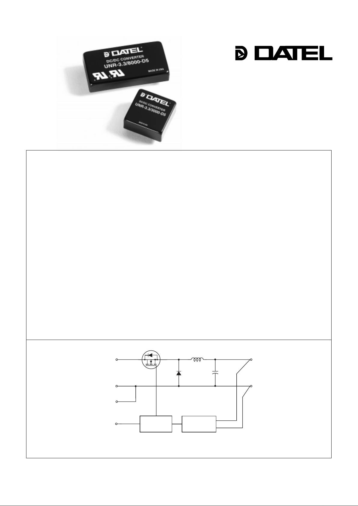
Figure 1. Simplified Schematic
Features
New low-voltage microprocessor and memory chips are driving the migration
from centralized to distributed power processing in modern telecommunication and
computer systems. Powering these new chips requires local, on-board power
converters that rapidly source large amounts of current while maintaining accurate
voltages with minimal ripple and noise. The distribution losses, unpredictable
regulation and poor transient response of traditional centralized power systems are
no longer acceptable. Power processing at the "point-of-use" is frequently the only
way to achieve desired performance.
DATEL’s new UNR Series of non-isolated, 3.3V output, 5V or 12V input, switching
DC/DC converters were specifically designed for on-board usage in today’s mixedlogic 5V/3.3V systems. They also support those systems that are already drawing
maximum current from their 5V buses and must resort to their 12V buses.
These low-cost, extremely efficient (typically 90%) power converters are capable
of delivering full rated output currents (2.5-12 Amps) while maintaining low case
temperatures without the need for heat sinks or any auxiliary cooling. UNR Series
devices combine proven circuit architectures, contemporary SMT-on-ceramic and
SMT-on-pcb assembly techniques, and a new thermally-conductive potting compound to achieve high output power in the smallest packages possible.
DATEL is currently developing UNR Series devices that incorporate active load
sharing with output current/voltage-sensing capabilities. We can also quickly modify
existing devices for application-specific output voltages from 1.8 to 5 Volts. Please
contact us with your unique requirements ... we may already have the product you
need.
DATEL also makes a complete line of isolated 3.3V DC/DC converters that
operate from wide-range input voltages from 4.6 to 72V.
Single Output
UNR Series
Non-Isolated, 3.3V
8-40 Watt, DC/DC Converters
••
••
•
Low cost
••
••
•
5V or 12V inputs
••
••
•
3.3V±1% (±33mV) outputs
••
••
•
±0.25% (±8mV) max. line regulation
••
••
•
±0.5% (±17mV) max. load regulation
••
••
•
Guaranteed efficiencies to 86%
••
••
•
Power densities to 29W/in
3
••
••
•
High output current ... small packages:
3A (1" x 1" package)
8A (2" x 1" package)
12A (2" x 2" package)
••
••
•
No heat sinks required
••
••
•
–40 to +100oC operating temperatures
••
••
•
On/off/sync control
••
••
•
UL, CSA, IEC safety approvals
••
••
•
Customized VOUT (Contact DATEL)
+V
IN
+V
OUT
PWM
CONTROLLER
REFERENCE &
ERROR AMP
INPUT
RETURN
LOGIC
GROUND
ON/OFF
CONTROL
OUTPUT
RETURN
DATEL, Inc., 11 Cabot Boulevard, Mansfield, MA 02048 (U.S.A.) • Tel: (508)339-3000, (800)233-2765 Fax: (508)339-6356 • Email: datellit@mcimail.com
INNOVATION and EX C ELL E N C E
®
®
Page 2
METAL CASE
INSULATED BASE
0.060 –0.002 DIA
PINS 3-6
(1.524 –0.051)
0.040 –0.002 DIA
PINS 1-2
(1.016 –0.051)
2.00
(50.80)
0.45
(11.3)
0.20 MIN
(5.08)
0.10
(2.54)
0.400
(10.160)
1
2
3
1.800
(45.720)
0.300
(7.620)
BOTTOM VIEW
4
6
0.60
(15.24)
2.00
(50.80)
0.200
(5.080)
5
0.800
(20.320)
METAL CASE
INSULATED BASE
0.040 –0.002 DIA
(1.016 –0.051)
2.00
(50.80)
0.45
(11.43)
0.20 MIN
(5.08)
0.10
(2.54)
0.800
(20.320)
0.300
(7.620)
1.800
(45.720)
0.200
(5.080)
1.00
(25.40)
BOTTOM VIEW
1
2
3
4
6
0.10
(2.54)
5
0.400
(10.160)
METAL CASE
INSULATED BASE
0.040 –0.002 DIA
(1.016 –0.051)
1.00
(25.40)
0.45
(11.43)
0.20 MIN.
(5.08)
0.200
(5.080)
0.10
(2.54)
BOTTOM VIEW
3
1.00
(25.40)
0.800
(20.320)
0.100
(2.540)
1
2
4
6
0.800
(20.320)
0.200
(5.080)
0.400
(10.160)
5
0.10
(2.54)
UNR-3.3/3000-D5 3.3 3000 140 ±0.25% ±0.5% 5 4.75-5.5 25/2390 85% C7, P9
UNR-3.3/2500-D12 3.3 2500 100 ±0.2% ±0.5% 12 10.8-13.2 35/856 82% C7, P10
UNR-3.3/8000-D5 3.3 8000 75 ±0.25% ±0.5% 5 4.75-5.5 25/6330 86% C5, P9
UNR-3.3/12000-D5 3.3 12000 125 ±0.25% ±0.75% 5 4.75-5.5 50/9700 84% C6, P9
UNR Series NON-ISOLATED, 3.3V, 8-40W DC/DC CONVERTERS
Performance Specifications and Or dering Guide
VOUT
(Volts)
Output
Package
(Case,
Pinout)
Efficiency
(Min.)
Regulation (Max.)
Line
VIN Nom.
(Volts)
Range
(Volts)
Model
Input
Input Volta ge Range:
D5 = 4.75-5.5 Volts (5V nominal)
D12 = 10.8-13.2 Volts (12V nominal)
Output Configuration:
U = Unipolar
2
Non-Isolated
Nominal Output Voltage:
3.3 Volts
Maximum Output Current
in mA
Mechanical Specifications
Part Number Structure
Mechanical Specifications
IOUT
(mA, Max.)
IIN ➃
(mA, Max.)
Function P9
Logic Gnd.
On/Off Control
+Output
Output Rtn.
Input Rtn.
+Input
I/O Connections
Function P10
Do Not Connect
No Connect
+Output
Output Rtn.
Input Rtn.
+Input
Pin
1
2
3
4
5
6
➀
Ripple/Noise
➁
(mVp-p, Max.)
Case C7
➀
T ypical at TA = +25°C under nominal line voltage and full load conditions unless otherwise noted. These de vices require e xternal input and output capacitors for normal operation.
➁
20MHz bandwidth. Specified with external I/O capacitors. See T echnical Notes .
➂
10% to 100% load.
➃
Nominal line voltage, no load/full load conditions.
Case C5
Case C6
Load
➂
U NR - 3.3 / 8000 - D5
Page 3

Performance/Functional Specifications
UNR Series
NON-ISOLATED, 3.3V, 8-40W DC/DC CONVERTERS
3
Typical @ TA = +25°C under nominal line voltage and full load conditions unless noted. ➀ ➁
Input
Input Voltage Range:
"D5" Models 4.75-5.5 Volts (5V nominal)
"D12" Models 10.8-13.2 Volts (12V nominal)
Input Current See Ordering Guide
Input Filter Type ➁ None
Overvoltage Shutdown None
Reverse-Polarity Protection Yes (Instantaneous, 10A maximum)
On/Off (Sync.) Control (Pin 2) ➂ TTL high = off, low (or open) = on
Output
V
OUT Accuracy (50% load) ±1%
Temperature Coefficient ±0.02% per °C
Ripple/Noise (20MHz BW) ➁ See Ordering Guide
Line/Load Regulation See Ordering Guide
Efficiency See Ordering Guide
Current Limiting Auto-recovery
Dynamic Characteristics
Transient Response (25% load step) 100µsec to ±1.5% of final value
Switching Frequency:
"D5" Models 75kHz (±5kHz)
"D12" Models 90kHz (±5kHz)
Environmental
Operating Temperature (ambient):
Without Derating:
3A an 8A "D5" Models –40 to +50°C
12A "D5" and 2.5A "D12" Models –40 to +45°C
With Derating to +100°C (See Derating Curves)
Storage Temperature –55 to +105°C
Physical
Dimensions:
3A "D5" and 2.5A "D12" Models 1" x 1" x 0.45" (25 x 25 x 11.4mm)
8A "D5" Model 2" x 1" x 0.45" (51 x 25 x 11.4mm)
12A "D5" Model 2" x 2" x 0.45" (51 x 51 x 11.4mm)
Shielding 5-sided ➃
Case Connection Pin 4 (Output Return)
Case Material Corrosion resistant steel with
epoxy-based enamel finish
Pin Material Brass, solder coated
Weight:
3A "D5" and 2.5A "D12" Models 1 ounce (28.4 grams)
8A "D5" Model 1.5 ounces (42.5 grams)
12A "D5" Model 2 ounces (56.7 grams)
➀ These power converters require a minimum 10% loading to maintain specified regulation.
Operation under no-load conditions will not damage these devices, however, they may
not meet all listed specifications.
➁ These power converters do not have internal input filters and do require external input
and output capacitors to achieve rated specifications. Application-specific internal input/
output filtering can be added upon request. Contact DATEL for details.
➂ On/Off Control pins are included on "D5" models only. See Technical Notes for details.
Applying a voltage to the Control pin when no input power is applied to the converter can
cause permanent damage to the converter.
➃ Cases can be provided with 6-sided shielding. Contact DATEL for details.
Absolute Maximum Ratings
These are stress ratings. Exposure of devices to any of these conditions
may adversely affect long-term reliability. Proper operation under conditions
other than those listed in the Performance/Functional Specifications Table is
not implied. Storage temperatures have been verified for 168 hours.
Input Voltage:
"D5" Models 7 Volts
"D12" Models 15 Volts
Input Reverse-Polarity Protection Current must be <10A. Brief
duration. Fusing recommended.
Output Overvoltage Protection None
Output Current Current limited. Max. current and
short-circuit duration model
dependent.
Storage Temperature –55 to +105°C
Lead Temperature (soldering, 10sec.) +300°C
Temperature Derating
Output Current (Amps)
Ambient Temperature (°C)
–40 0 40 45 50 55 60 65 70 75 80 85 90 95 100
20
19
18
17
16
15
14
13
12
11
10
9
8
7
6
5
4
3
2
1
0
A
B
UNR-3.3/12000-D5 A
UNR-3.3/8000-D5 B
UNR-3.3/3000-D5 C
UNR-3.3/2500-D12 D
C
D
Page 4

4
UNR Series NON-ISOLATED, 3.3V, 8-40W DC/DC CONVERTERS
1000
100
10
4.75 4.80 4.85 4.90 4.95 5.00 5.05 5.10 5.15 5.20 5.25 5.30 5.35 5.40 5.45 5.50 0.3 0.6 0.9 1.2 1.5 1.8 2.1 2.4 2.7 3.0
2
1.75
1.50
1.25
1
0.75
0.50
0.25
0
Input Capacitance (µF)
C
IN
RMS Ripple Current (Amps)
Output Load Current (Amps)
Input Voltage (Volts)
C
IN
RMS Ripple Current vs. I
LOAD
Minimum Input Capacitor Value vs. V
IN @
Full Load
5.15 5.20 5.25 5.30 5.35 5.40 5.45 5.504.75 4.80 4.85 4.90 4.95 5.00 5.05 5.10
10000
1000
100
Input Capacitance (µF)
Minimum Input Capacitor Value vs. V
IN @
Full Load
1 2 3 4 5 6 7 8 9 10 11 12
8
7
6
5
4
3
2
1
0
C
IN
RMS Ripple Current (Amps)
Output Load Current (Amps)
Input Voltage (Volts)
C
IN
RMS Ripple Current vs. I
LOAD
UNR-3.3/12000-D5
UNR-3.3/8000-D5
UNR-3.3/3000-D5
Input Capacitors
As shown in the simplified schematic, UNR Series power converters do not
have internal input capacitors. Users must install external input capacitors
for the devices to achieve specified operation. The input capacitor functions
as a true energy-storage element. Its required capacitance varies as a
function of applied line voltage. Additionally, as the power converter’s input
FET switch cycles on and off, the input capacitor must have the ability to
rapidly supply pulses of relatively high current. Therefore, required rmsripple-current capabilities of the input capacitor will vary as a function of the
power converter’s load current. Rather than install a large, expensive,
internal capacitor that addresses all possible load conditions, we have
chosen to leave the capacitor out so that you may select a cost-effective
component appropriate to your particular application.
Use the charts below to determine how much input capacitance is required
as a function of input voltage and also to determine the required rms-ripplecurrent capabilities of the needed capacitor as a function of output load
current. Note that "low-line" conditions will require proportionally more input
capacitance in order to maintain the required energy levels and that higher
output currents will obviously require higher input currents. Contact DATEL’s
Applications Engineering Group if you have any questions.
Technical Notes
4.75 4.80 4.85 4.90 4.95 5.00 5.05 5.10
1 2 3 4 5 6 7 8
10000
1000
100
5.15 5.20 5.25 5.30 5.35 5.40 5.45 5.50
4
3.5
3
2.5
2
1.5
1
0.5
0
Input Capacitance (µF)
C
IN
RMS Ripple Current (Amps)
Output Load Current (Amps)
Input Voltage (Volts)
C
IN
RMS Ripple Current vs. I
LOAD
Minimum Input Capacitor Value vs. V
IN @
Full Load
Page 5

UNR Series
NON-ISOLATED, 3.3V, 8-40W DC/DC CONVERTERS
5
Synchronization
If desired, a synchronizing clock can be applied to pin 2 on "D5" models to
control the converter’s internal clock oscillator. The applied clock should be a
square wave with a maximum 1µsec "high" duration and an amplitude
between +2V and +5V (see On/Off Control) referenced to pin 1 (Logic
Ground). The frequency of the synchronizing clock must be higher than that
of the standalone converter. Therefore, it should be 85kHz ±5kHz.
Synchronization Issues
Because of the comparatively small differential between their input and
output voltages, 5V-to-3.3V DC/DC conv erters capable of sourcing high
output current also demand high input current. Most of these high-current
DC/DC’s use switching architectures employing fixed-frequency clock
oscillators, and their input currents include both dc (average) and ac (ripple)
components.
If you have multiple DC/DC’s connected to a single main power bus, you may
need to consider that all the converters will not be switching at exactly the
same frequency (due to normal component and manufacturing tolerances).
Consequently, the converters may randomly "self-synchronize" in their
demanding of peak current from the main power bus. Peak currents all
drawn simultaneously can be significantly greater than the sum of average
input currents. This phenomenon can result in unwanted harmonic
interactions from converter to converter along the power bus.
One solution to this potential problem is to use the converters' On/Off Control
function to effectively "de-synchronize" their clocks. Forcing the multiple
clocks to be out of phase with each other relaxes the required performance
characteristics of the main power bus so the bus now has to carry the sum of
the average currents of all the converters plus only one peak current.
Reducing Output Ripple/Noise
In addition to their internal output capacitors, UNR Series DC/DC converters
require the installation of external output capacitors to achieve their
published ripple/noise specifications. The selected caps should be low-ESR,
tantalum or electrolytic types, and they should be located as close to the
converters as possible. Recommended values are listed in the table below.
Part Number Output Capacitor
UNR-3.3/3000-D5 470µF, 6V, Low ESR
UNR-3.3/2500-D12 100µF, 6V, Low ESR
UNR-3.3/8000-D5 1000µF, 6V, Low ESR
UNR-3.3/12000-D5 1000µF, 6V, Low ESR
Remote On/Off Control and the Logic Ground Pin
The On/Off Control pin (pin 2 on "D5" units) may be used for digitally
controlled on/off operation. A TTL logic high (+2 to +5 Volts, 250µA max.)
applied to pin 2 disables the converter. A TTL logic low (0 to +0.8 Volts,
70µA max.), or no connection, enables the converter. Control voltages
should be referenced to pin 1 (Logic Ground). Applying a voltage to the
Control pin when no input power is applied to the converter can cause
permanent damage to the converter.
The Input Return (pin 5), Output Return (pin 4) and Logic Ground (pin 1 on
"D5" models) are all tied together internal to the device. To the extent
possible, load current should be returned to pin 4. Pin 5 should be
connected back to the input supply with as low an impedance as possible so
that input return current flows through pin 5. The internal trace leading to the
Logic Ground pin is not designed to carry high currents. Devices should not
be installed in a manner that results in high current flow through pin 2 (i.e.,
pins 4 and 5 should never be left open or attached via high-impedance
connections).
"D12" models do not have On/Off Control functions. Their pin 2 (No
Connect) is not electrically connected to any internal circuitry and may be
tied to any convenient external run. Their pin 1 (Do Not Connect) is a test
point. Pin 1 may be soldered to an island for mechanical mounting
purposes, but it should not have an electrical connection to external circuitry.
Page 6

DATEL, Inc. 11 Cabot Boulevard, Mansfield, MA 02048-1151
Tel: (508) 339-3000 (800) 233-2765
Fax: (508) 339-6356 Email: datellit@mcimail.com
Data Sheet Fax Back: (508) 261-2857
6
DATEL makes no representation that the use of its products in the circuits described herein, or the use of other technical information contained herein, will not infringe upon existing or future patent rights. The descriptions contained herein
do not imply the granting of licenses to make, use, or sell equipment constructed in accordance therewith. Specifications are subject to change without notice. The DATEL logo is a registered DATEL, Inc. trademark.
DATEL (UK) LTD. Tadley, England Tel: (01256)-880444
DATEL S.A.R.L. Montigny Le Bretonneux, France Tel: 01-34-60-01-01
DATEL GmbH München, Germany Tel: 89-544334-0
DATEL KK Tokyo, Japan Tel: 3-3779-1031, Osaka Tel: 6-354-2025
DS-0329C 3/97
EMI Radiated Emissions
If you’re designing with EMC in mind, please note that all of DATEL’s UNR
8-40 Watt DC/DC Converters have been characterized for radiated and
conducted emissions in our new EMI/EMC laboratory. Testing is conducted
in an EMCO 5305 GTEM test cell utilizing EMCO automated EMC test
software. Radiated emissions are tested to the limits of FCC Part 15, Class
B and CISPR 22 (EN 55022), Class B. Correlation to other specifications can
be supplied upon request. Radiated emissions plots to FCC and CISPR 22
for model UNR-3.3/8000-D5 appear below. Published EMC test reports are
available for each model number. Contact DATEL’s Applications Engineering
Department for more details.
Custom Capabilities
DATEL’s world-class design, development and manufacturing team stands
ready to work with you to deliver the exact power converter you need for
your demanding, large volume, OEM applications. And ... we’ll do it on time
and within budget!
Our experienced applications and design staffs; quick-turn prototype
capability; highly automated, SMT assembly facilities; and in-line SPC
quality-control techniques combine to give us the unique ability to design
and deliver any quantity of power converters to the highest standards of
quality and reliability.
We have compiled a large library of DC/DC designs that are currently used
in a variety of telecom, medical, computer, railway, aerospace and industrial
applications. We may already have the converter you need.
Contact us. Our goal is to provide you the highest-quality, most costeffective power converters available.
UNR Series
NON-ISOLATED, 3.3V, 8-40W DC/DC CONVERTERS
80
70
60
50
40
30
20
10
0
–10
–20
Frequency (MHz)
100 1000
Radiated Emissions
FCC Class B Limit
UNR-3.3/8000-D5 Radiated Emissions
FCC Part 15 Class B, 3 Meters
Converter Output = 3.3Vdc @ 6.4A
Radiated Emissions (dBµV/M)
UNR-3.3/8000-D5 Radiated Emissions
EN 55022 Class B, 10 Meters
Converter Output = 3.3Vdc @ 6.4A
80
70
60
50
40
30
20
10
0
–10
–20
Frequency (MHz)
100 1000
Radiated Emissions
EN 55022 Class B Limit
Radiated Emissions (dBµV/M)
INNOVAT ION an d EX C ELL E N C E
®
®
ISO 9001
ISO
9001
REGISTERED
Page 7

INNOVATION and EX C ELL E N C
E
®
®
DATEL, Inc., 11 Cabot Boulevard, Mansfield, MA 02048 • Tel: (508)339-3000 Fax: (508)339-6356 • Email: sales@datel.com
Data sheet fax back: (508)261-2857
• •
• •
•
Visit us on the internet: www.datel.com
3
12 (6-16.5) 2 x 0.4 x 0.8 ➃B1, P18 ±0.5% ±1.5% 50 92%
➅
UNS-5/3-D12 UNS, 10/15W
12 (6-16.5) 2 x 0.8 x 0.4 ➄B2, P18 ±0.5% ±1.5% 50 92%
➅
UNS-5/3-D12D UNS, 10/15W
5 ➆
12 (10.4-13.6) 2 x 1 x 0.5 C13, P21 ±0.25% ±0.5% 60 87% UNR-5/5-D12 UNR, 25W
5V
SINGLE OUTPUT
5V
SINGLE OUTPUT
5 (4.75-5 .5) 1 x 1 x 0.45 C7, P9 ±0.4% ±0.5% 30 86% UNR-3.3/3-D5 UNR, 10W.
3
7.5 (4.75-13.6) 2 x 0.4 x 0.8 ➃B1, P18 ±0.5% ±1.5% 50 90%
➅
UNS-3.3/3-D5 UNS, 10/15W
7.5 (4.75-13.6) 2 x 0.8 x 0.4 ➄B2, P18 ±0.5% ±1.5% 50 90%
➅
UNS-3.3/3-D5D UNS, 10/15W
12 (10.4-13.6) 1 x 1 x 0.45 C7, P9 ±0.25% ±0.5% 9 0 87% UNR-3.3/3-D12 UNR, 10W
8
5 (4.75-5. 5) 2 x 1 x 0.375 C5A, P9 ±0.1% ±0.5% 40 88% UNR-3.3/8-D5 UNR, 26/33W
12 (10.4-13.6) 2 x 1 x 0.375 C5A, P9 ±0.1% ±0.5% 60 86% UNR-3.3/8-D12 UNR, 26/33W
10
5 (4.75-5. 5) 2 x 1 x 0.375 C5A, P9 ±0.1% ±0.5% 40 86% UNR-3.3/10-D5 UNR, 26/33W
12 (10.4-13.6) 2 x 1 x 0.375 C5A, P9 ±0.1% ±0.5% 60 85% UNR-3.3/10-D12 UNR, 26/33W
12
5 (4.75-5. 5) 2 x 1 x 0.375
➂
±0.25% ±0.5% 50 87% UNR-3.3/12-D5
➂
Contact DA TEL
15
5 (4.75-5. 5) 2 x 2 x 0.45
➂
±0.25% ±0.5% 50 84% UNR-3.3/15-D5
➂
Contact DA TEL
3.3V
SINGLE OUTPUT
3.3V
SINGLE OUTPUT
2
5 (4.75-5 .5) 1 x 1 x 0.45 C7, P9 ±0.4% ±0.5% 30 83% UNR-2.5/2-D5 UNR, 5W
8
5 (4.75-5. 5) 2 x 1 x 0.375 C5A, P9 ±0.1% ±0.5% 40 86% UNR-2.5/8-D5 UNR, 20/25W
12 (10.4-13.6) 2 x 1 x 0.375 C5A, P9 ±0.1% ±0.5% 60 85% UNR-2.5/8-D12 UNR, 20/25W
10
5 (4.75-5. 5) 2 x 1 x 0.375 C5A, P9 ±0.1% ±0.5% 40 85% UNR-2.5/10-D5 UNR, 20/25W
12 (10.4-13.6) 2 x 1 x 0.375 C5A, P9 ±0.1% ±0.5% 60 83% UNR-2.5/10-D12 UNR, 20/25W
12
5 (4.75-5. 5) 2 x 1 x 0.375
➂
±0.25% ±0.5% 50 86% UNR-2.5/12-D5
➂
Contact DA TEL
20
5 (4.75-5. 5) 2 x 2 x 0.45
➂
±0.25% ±0..5% 50 84% UNR-2.5/20-D5
➂
Contact DA TEL
Output Input Voltage, Ripple /
Current Nominal (Range) Dimensions Case, Line Load Noise
➁➁
➁➁
➁
Efficiency DATEL DATEL
(Amps, Max.) (Volts) (Inches) Pinout (Max.) (Max.) (mVp-p) (Min.) Model Number Data Sheet
Package
➀➀
➀➀
➀
Regulation
Listed specifications are typical at TA = +25°C under nominal line voltage and full-load conditions unless noted.
➀
See individual product data sheets for mechanical specifications and pinouts.
➁
Ripple/Noise is specified over a 20MHz bandwidth.
➂
Listed specifications for these products are preliminary.
➃
10-pin SIP package.
➄
10-pin DIP package.
➅
Listed specification is a typical.
➆
Output voltage is user adjustable from 3.3 to 6V.
.
2.5V
SINGLE OUTPUT
2.5V
SINGLE OUTPUT
N
ON-ISOLATED
DC/DC C
ONVERTER SELECTION
G
UIDE
N
ON-ISOLATED
DC/DC C
ONVERTER SELECTION
G
UIDE
 Loading...