

Page 1

INTEGRATED CIRCUITS
DATA SH EET
UBA2050(A); UBA2051(A;C)
One-chip telephone ICs with
speech, dialler and ringer functions
Product specification
Supersedes data of 1998 Mar 24
File under Integrated Circuits, IC03
2000 May 19
Page 2

Philips Semiconductors Product specification
One-chip telephone ICs with speech,
dialler and ringer functions
FEATURES
Speech/transmission part
• Low DC line voltage; operates down to 1.45 V
(excluding voltage drop over external polarity guard)
• Line voltage regulator with adjustable DC voltage
• Regulated 3.3 V supply (VDD) for the dialler part and
peripherals compatible with:
– Speech mode
– Ringer mode
– Trickle mode.
• Unregulated supply (VCC) for the transmission part and
peripherals
• Transmit stage with:
– Microphone amplifier with symmetrical
high-impedance inputs
– DTMF input with confidence tone on receive output.
• Receive stage with:
– Receive amplifier with asymmetrical output
– Earpiece amplifier with adjustable gain (and gain
boost facility) for all types of earpieces.
• AGC: line loss compensation for microphone and
receive amplifiers.
Dialler part
• Last Number Redial (LNR) (32 digits)
• Pulse dialling:
– 10 PPS and 20 PPS (resistor option)
– M/B 2 : 3 and 1 : 2 (resistor option).
• DTMF timing:
– Manual diallingwith minimum duration for bursts and
pauses (85/85 ms)
– Calibrated timing during redialling (85/85 ms).
• Pulse or tone mode select at start-up (resistor option)
• Flash function (600, 300, 98 and 80 ms) (resistor
options)
• Access pause time 2.0 and 3.6 s (resistor option);
access pauses in series are possible
UBA2050(A); UBA2051(A;C)
•[∗/T] key (for mixed mode dialling) or separate
[P → T] key
• Repertory memory integrity check
• Keytone generation (only UBA2050, UBA2050A and
UBA2051C)
• Dial Mode Output (DMO) function during pulse dialling
and flash function (only UBA2050 and UBA2051)
• LED output for DTMF dialling indication (only
UBA2050A and UBA2051A)
• Function keys:
– [LNR/P], [R] and [P → T]
– [STORE], [MEM], [M1], [M2] and [M3]
(only UBA2051, UBA2051A and UBA2051C).
• Resistor options:
– [∗/T] key definition (MMS)
– Pulse or Tone mode Selection (PTS)
– Flash Time Selection (FTSA and FTSB)
– Make/Break ratio Selection (MBS)
– Pulses Per Second (PPS)
– Access Pause Time (APT).
• 13 repertory numbers (only UBA2051, UBA2051A and
UBA2051C):
– 3 direct memories (21 digits)
– 10 indirect memories (21 digits).
• Supply and temperature independent tone output
• On-chip DTMF filtering for low output distortion
(
“CEPT CS 203”
• On-chip oscillator suitable for low-cost 3.579545 MHz
quartz crystal or ceramic resonator
• Uses standard single-contact keyboard
• Keyboard entries fully debounced.
Ringer part
• Ringer input frequency discrimination
• 3-toneringer with 4 programmable melodies (selectable
via keyboard by keys [1] to [4])
• 4-level volume control (selectable via keyboard by
keys [5] to [8]).
compatible)
2000 May 19 2
Page 3
Philips Semiconductors Product specification
One-chip telephone ICs with speech,
dialler and ringer functions
GENERAL DESCRIPTION
TheICs UBA2050,UBA2050A,UBA2051,UBA2051Aand
UBA2051C contain all the functionsneeded to build a fully
electronic telephone set.
In many places in the text, figures and tables, the
description is not applicable for all the five types, but only
for one or two or for a combination. These combinations
will be referred to by means of short denotations as given
in Table 1.
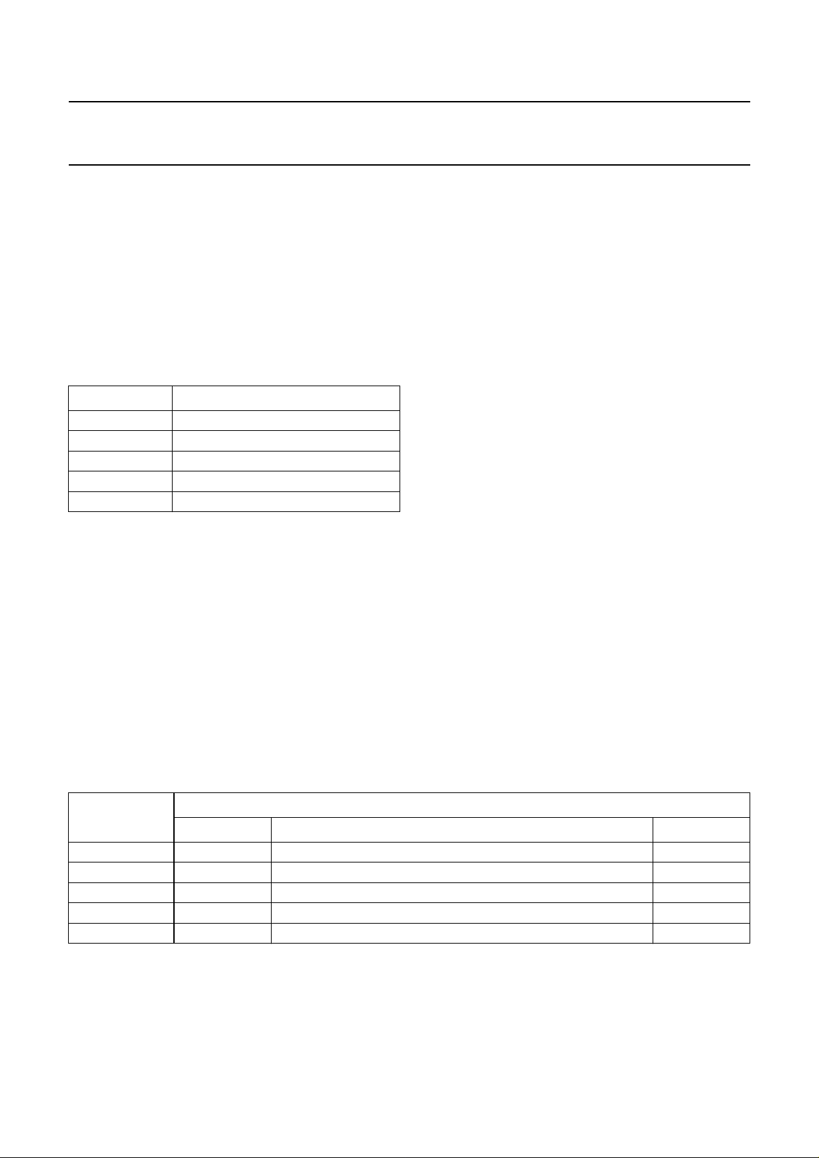
Table 1 Denotations of types
DENOTATION TYPES
UBA2050x UBA2050; UBA2050A
UBA2051x UBA2051; UBA2051A; UBA2051C
UBA205x UBA2050; UBA2051
UBA205xA UBA2050A; UBA2051A
UBA205xx all five types
UBA2050(A); UBA2051(A;C)
When the line current is high enough, a fixed amount of
current is derived from pin LN in order to create a supply
point at pin V
3.3 V to supply the dialler and ringer parts and peripheral
circuits.
Dialler part
The dialler and ringer parts of the IC are responsible for
the system control, system settings and the generation
and detection of various signals.
The dialler offers a 32-digit last number redial function.
The UBA2051x offers in addition 13 memories
(3 direct + 10 indirect) of 21 digits.
During pulse dialling the DMO output of the UBA205x can
be used to decrease the line voltage. During tone dialling
theLED output ofthe UBA205xA is usedto indicate DTMF
dialling. A keytone is available if a valid key is pressed for
the types UBA2050x and UBA2051C.
. The voltage at pin VDD is regulated at
DD
Ringer part
The devices incorporate a speech/transmission part, a
dialler part and a ringer part. By offering a wide range of
possible adaptations for each part, the UBA205xx
applications can be easily adapted to meet different
requirements.
Speech/transmission part
The speech/transmission part performs all transmission
and line interface functions required in fully electronic
telephone sets. It performs electronic switching between
transmissionand dialling. The IC operates ataDC voltage
downto 1.45 V (with reduced performance)to facilitate the
use of telephone sets connected in parallel.
ORDERING INFORMATION
TYPE NUMBER
NAME DESCRIPTION VERSION
UBA2050T SO28 plastic small outline package; 28 leads; body width 7.5 mm SOT136-1
UBA2050AT SO28 plastic small outline package; 28 leads; body width 7.5 mm SOT136-1
UBA2051T SO28 plastic small outline package; 28 leads; body width 7.5 mm SOT136-1
UBA2051AT SO28 plastic small outline package; 28 leads; body width 7.5 mm SOT136-1
UBA2051CT SO28 plastic small outline package; 28 leads; body width 7.5 mm SOT136-1
The ringer part offers a discriminator input which enables
the MDY/TONE output as soon as a valid ring frequency is
detected. It offers a choice of 4 different 3-tone melodies
and a 4-level volume control, both programmable via the
keyboard. An external very low cost ringer output stage for
a buzzer is needed. Stabilized supply (VDD) during ringer
mode for dialler and ringer part is included.
PACKAGE
2000 May 19 3
Page 4
Philips Semiconductors Product specification
One-chip telephone ICs with speech,
UBA2050(A); UBA2051(A;C)
dialler and ringer functions
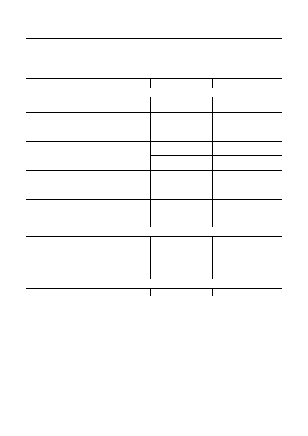
QUICK REFERENCE DATA
SYMBOL PARAMETER CONDITIONS MIN. TYP. MAX. UNIT
Speech/transmission part
I
line
V
LN
I
CC
V
CC
V
DD
I
DD
G
v(TX)
G
v(RX)
∆G
v(QR)
∆G
v(trx)
∆G
v(trx)(m)
Dialler part
V
HG(LN)(rms)
V
LG(LN)(rms)
G
V
THD total harmonic distortion −−25 − dB
Ringer part
f
ring
line current operating range normal operation 11 − 140 mA
with reduced performance 1 − 11 mA
DC line voltage I
= 15 mA 4.05 4.35 4.65 V
line
internal current consumption VCC= 3.6 V − 1.25 1.5 mA
supply voltage for internal circuitry
IP=0mA − 3.6 − V
(unregulated)
regulated supply voltage for peripherals speech mode;
3.0 3.3 3.6 V
IDD= −2.6 mA
ringer mode; I
= 75 mA 3.0 3.3 3.6 V
DD
available supply current for peripherals −−−2.6 mA
typical voltage gain for microphone
V
= 4 mV (RMS) 43.2 44.2 45.2 dB
MIC
amplifier
typical voltage gain for receiving amplifier VIR= 4 mV (RMS) 32.4 33.4 34.4 dB
gain setting range for earpiece amplifier RE1= 100 kΩ−14 − +12 dB
gain control range for microphone and
receive amplifiers
gain reduction for microphone and receive
I
= 85 mA; referenced to
line
I
=15mA
line
− 6.0 − dB
in DTMF mode − 80 − dB
amplifiers
high group frequency voltage (RMS value)
on line
low group frequency voltage (RMS value)
on line
R
DTMF1
R
DTMF2
R
DTMF1
R
DTMF2
=20kΩ;
= 2.74 kΩ
=20kΩ;
= 2.74 kΩ
353 435 536 mV
277 341 420 mV
pre-emphasis of group 1.5 2.0 2.5 dB
ringer detection frequency 13 −−Hz
2000 May 19 4
Page 5
This text is here in white to force landscape pages to be rotated correctly when browsing through the pdf in the Acrobat reader.This text is here in
u
_white to force landscape pages to be rotated correctly when browsing through the pdf in the Acrobat reader.This text is here inThis text is here in
white to force landscape pages to be rotated correctly when browsing through the pdf in the Acrobat reader. white to force landscape pages to be ...
2000 May 19 5
ll pagewidth
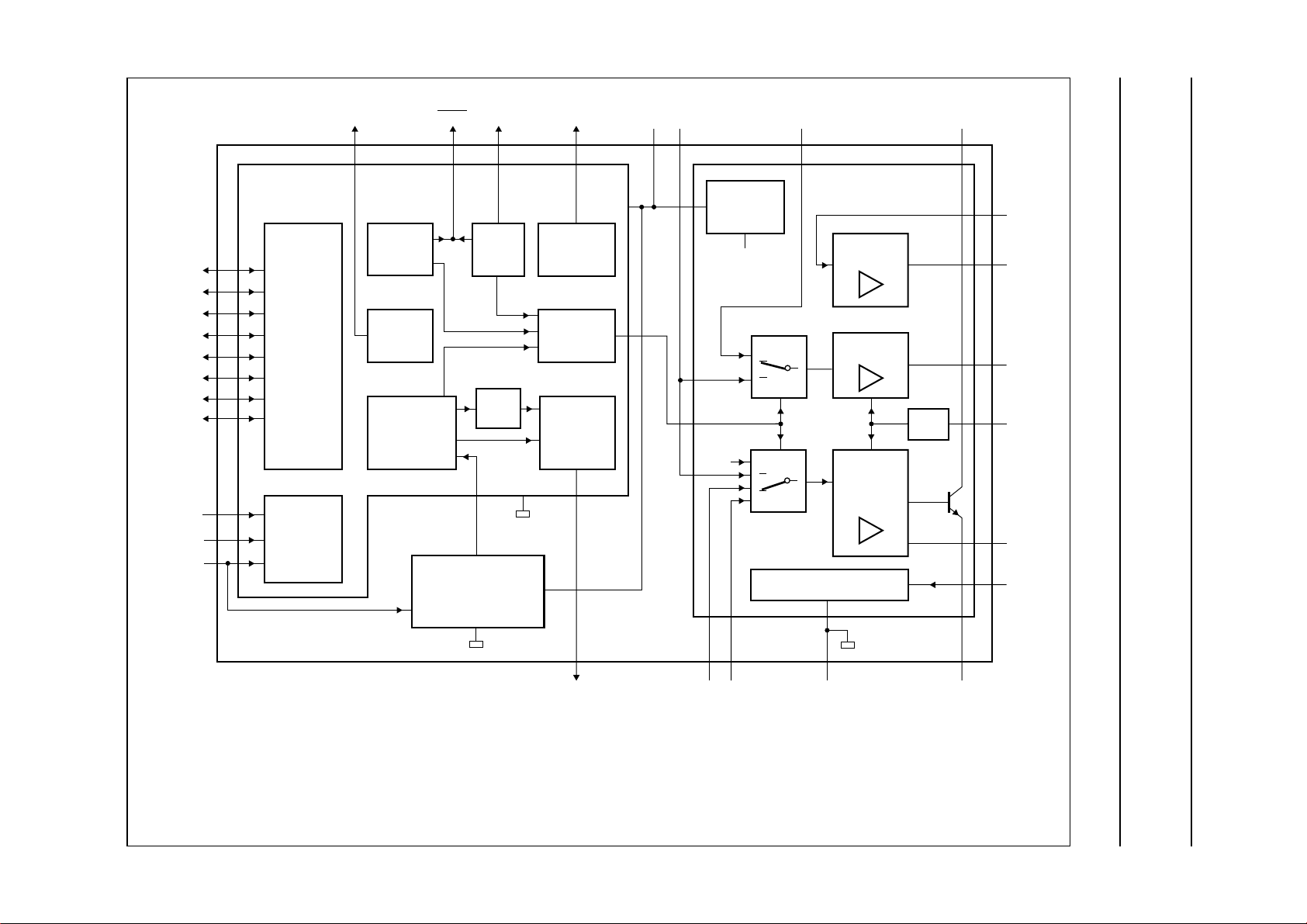
BLOCK DIAGRAM
Philips Semiconductors Product specification
One-chip telephone ICs with speech,
dialler and ringer functions
R1
R2
R3
R4
C1
C2
C3
C4
XTAL
CE/CSI
CE/FDI
DIALLER
PART
KEYBOARD
DETECTOR
TIMING/
CONTROL
FLASH
KEYTONE
TONE
GENERATOR
DMODP/FLKT
PULSE
dB
MDY
RINGER
PART
DETECTOR/
GENERATOR
LED
DTMF
INDICATION
MUTE
DTMF/
RINGER
V
DD
UBA205xx
DTMF
V
DD
REGULATOR
V
CC
SLPE
IR
SPEECH/TRANSMISSION
PART
EARPIECE
AMPLIFIER
RECEIVE
AMPLIFIER
TRANSMIT
AMPLIFIER
SUPPLY
AGC
LN
GAR
QR
RX
AGC
REG
V
FCA138
UBA2050(A); UBA2051(A;C)
CC
UBA2050 and UBA2050A: C4 output not available.
UBA2051 and UBA2051A: KT output not available.
UBA2050 and UBA2051: DMO output available, LED output not available.
UBA2050A and UBA2051A: LED output available, DMO output not available.
UBA2051C: KT output available, DMO and LED outputs not available.
MDY/TONE
Fig.1 Block diagram.
MIC+ MIC−
GND
SLPE
Page 6
Philips Semiconductors Product specification
One-chip telephone ICs with speech,
UBA2050(A); UBA2051(A;C)
dialler and ringer functions
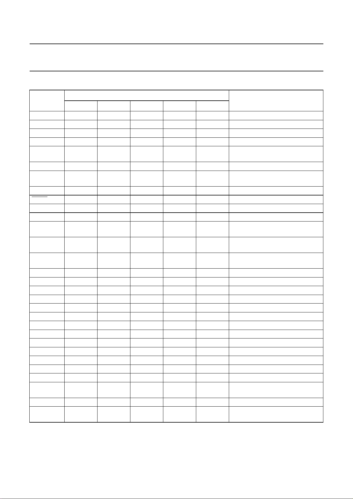
PINNING
SYMBOL
LN 11111positive line terminal
SLPE 22222slope (DC resistance) adjustment
REG 33333line voltage regulator decoupling
IR 44444receive amplifier input
AGC 55555automatic gain control and line-loss
DTMF 66666DTMF transmit input
V
DD
XTAL 88888oscillator input
DP/FL 99999dial pulse/flash output (active LOW)
DMO 10 − 10 −−dial mode output
LED − 10 − 10 − DTMF mode indication output
CE/CSI 11 11 11 11 11 chip enable/cradle switch input;
CE/FDI 12 12 12 12 12 chipenable/frequencydiscrimination
MDY/TONE 13 13 13 13 13 melody (ringer) output/DTMF
KT 14 14 −−10 keytone output
C4 −−14 14 14 keyboard input/output C4
C3 15 15 15 15 15 keyboard input/output C3
C2 16 16 16 16 16 keyboard input/output C2
C1 17 17 17 17 17 keyboard input/output C1
R4 18 18 18 18 18 keyboard input/output R4
R3 19 19 19 19 19 keyboard input/output R3
R2 20 20 20 20 20 keyboard input/output R2
R1 21 21 21 21 21 keyboard input/output R1
GND 22 22 22 22 22 negative line terminal
QR 23 23 23 23 23 earpiece amplifier output
GAR 24 24 24 24 24 gain adjustment earpiece amplifier
RX 25 25 25 25 25 receive amplifier output
MIC+ 26 26 26 26 26 non-inverting microphone amplifier
MIC− 27 27 27 27 27 inverting microphone amplifier input
V
CC
UBA2050 UBA2050A UBA2051 UBA2051A UBA2051C
77777stabilized supply for dialler and
28 28 28 28 28 supply for speech/transmission part
PIN
DESCRIPTION
compensation
ringer parts
note 1
input
generator output
input
and peripherals
Note
1. The cradle switch and the two positions ‘handset on the cradle’ and ‘handset lifted’ are further on in this document
referred to as ‘hook-switch’, respectively ‘on-hook’ and ‘off-hook’ position.
2000 May 19 6
Page 7

Philips Semiconductors Product specification
One-chip telephone ICs with speech,
dialler and ringer functions
handbook, halfpage
MDY/TONE
LN
SLPE
REG
AGC
DTMF
V
DD
XTAL
DP/FL
DMO
CE/CSI
CE/FDI
KT
1
2
3
IR
4
5
6
7
UBA2050T
8
9
10
11
12
13
MGT042
V
28
CC
MIC−
27
MIC+
26
RX
25
GAR
24
23
QR
GND
22
21
R1
R2
20
R3
19
R4
18
C1
17
C2
16
1514
C3
handbook, halfpage
MDY/TONE
UBA2050(A); UBA2051(A;C)
LN
SLPE
REG
AGC
DTMF
V
DD
XTAL
DP/FL
LED
CE/CSI
CE/FDI
KT
1
2
3
IR
4
5
6
7
UBA2050AT
8
9
10
11
12
13
MGT043
V
28
CC
MIC−
27
MIC+
26
RX
25
GAR
24
23
QR
GND
22
21
R1
R2
20
R3
19
R4
18
C1
17
C2
16
1514
C3
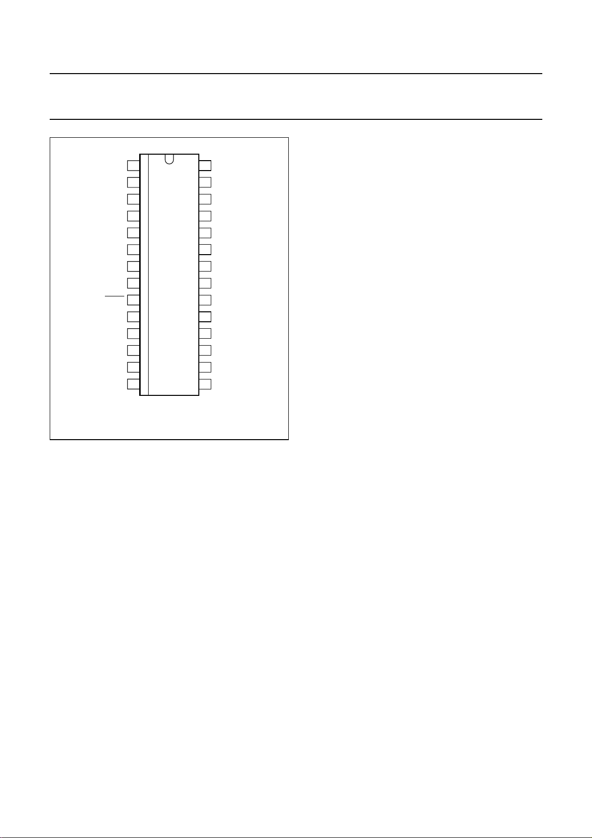
Fig.2 Pin configuration (UBA2050T).
handbook, halfpage
MDY/TONE
LN
SLPE
REG
AGC
DTMF
V
DD
XTAL
DP/FL
DMO
CE/CSI
CE/FDI
C4
Fig.3 Pin configuration (UBA2050AT).
1
2
3
IR
4
5
6
7
UBA2051T
8
9
10
11
12
13
MGT044
V
28
CC
MIC−
27
MIC+
26
RX
25
GAR
24
23
QR
GND
22
21
R1
R2
20
R3
19
R4
18
C1
17
C2
16
1514
C3
handbook, halfpage
MDY/TONE
LN
SLPE
REG
AGC
DTMF
V
DD
XTAL
DP/FL
LED
CE/CSI
CE/FDI
C4
1
2
3
IR
4
5
6
7
UBA2051AT
8
9
10
11
12
13
MGT045
V
28
CC
MIC−
27
MIC+
26
RX
25
GAR
24
23
QR
GND
22
21
R1
R2
20
R3
19
R4
18
C1
17
C2
16
1514
C3
Fig.4 Pin configuration (UBA2051T).
2000 May 19 7
Fig.5 Pin configuration (UBA2051AT).
Page 8
Philips Semiconductors Product specification
One-chip telephone ICs with speech,
dialler and ringer functions
handbook, halfpage
MDY/TONE
LN
SLPE
REG
AGC
DTMF
V
DD
XTAL
DP/FL
KT
CE/CSI
CE/FDI
C4
1
2
3
IR
4
5
6
7
UBA2051CT
8
9
10
11
12
13
FCA128
V
28
CC
MIC−
27
MIC+
26
RX
25
GAR
24
23
QR
GND
22
21
R1
R2
20
R3
19
R4
18
C1
17
C2
16
1514
C3
UBA2050(A); UBA2051(A;C)
The reference voltage can beincreased by connectingthe
resistorR
connecting the resistor RVA between pins REG and LN.
The voltage at pin REG is used by the internal regulator to
generate V
connected between pins REG and GND. This capacitor,
converted into an equivalent inductance (see Section “Set
impedance”), realizes the set impedance conversion from
its DC value (R
frequency range).
The voltage at pin SLPE is proportional to the line current,
and the voltage VLNat pin LN can be calculated as follows:
VLN=V
I
SLPE=Iline
where:
I
line
ICC= internal current consumption
IP= supply current for peripheral circuits
I
SUP
pin LN.
betweenpinsREGandSLPEordecreasedby
VA
and is decoupled by capacitor C
ref
SLPE
ref+RSLPE
− ICC− IP− I
) to its AC value (RCCin the audio
× I
SLPE
SUP
REG
= line current
= current consumed by the VDD regulator from
Fig.6 Pin configuration (UBA2051CT).
FUNCTIONAL DESCRIPTION
The values given in the functional description are typical
values unless otherwise specified.
For numbering of components, refer to Figs 7, 37 and 38.
Voltage levels are referenced to the negative line terminal
GND, except when otherwise specified.
Speech/transmission part
SUPPLY
The supply for the IC andits peripheral circuits is obtained
from the telephone line (see Fig.7).
Line interface (pins LN, SLPE and REG)
The IC generates a stabilized reference voltage V
ref
between pins LN and SLPE. This reference voltage is
4.15 V, is temperature compensated and can be adjusted
by means of an external resistor RVA.
Resistor R
pins SLPE and GND. The preferred value for R
20 Ω. Changing the value of R
is an external resistor connected between
SLPE
will affect more than
SLPE
SLPE
is
the DC characteristics: it also influences the microphone
and DTMF gains, the gain control characteristics, the
sidetone level and the maximum output swing on the line.
The DC current flowing into the set is determined by the
exchange supply voltage (V
resistance (R
(R
) and thereference voltage (V
line
), the DC resistance of the telephone line
exch
), the feeding bridge
exch
). The excesscurrent
ref
is shunted via pin LN to pin SLPE when the line current
(I
) is greater than the sum of the supply current of the
line
speech/transmission part (ICC), the current drawn by the
peripheral circuitry connected to VCC(IP) and the input
currentoftheVDDregulator(I
I
(9 mA), the internal referencevoltage (generating V
low
).Withlinecurrents below
SUP
ref
is automatically adjusted to a lower value.
This means that more sets can operate in parallel with
DC line voltages (excluding the polarity guard) down to an
absolute minimum voltage of 1.45 V. At line currents
below I
, the circuit has limited sending and receiving
low
levels. This is called the low voltage area.
)
2000 May 19 8
Page 9

Philips Semiconductors Product specification
One-chip telephone ICs with speech,
dialler and ringer functions
Internal supply (pin VCC)
The internal transmission part circuitry is supplied from
VCC. This supply voltage is derived from the voltage on
pin LN by means of resistor RCC and must be decoupled
by capacitor C
This supply point may also be used to supply peripheral
circuits e.g. an electretmicrophone taking intoaccount the
supply possibilities according to Fig.8.
handbook, full pagewidth
R
V
connected between pins VCCand GND.
VCC
I
line
from preamp
exch
exch
R
line
SUPPLY TRANSMISSION PART
REG
LN
REGULATOR
SLPE
UBA2050(A); UBA2051(A;C)
The voltage V
consumed by the transmission part and the peripheral
circuits:
VCC=V
CC0
where:
V
CC0=VLN
I
= the current consumed by the output stage of the
REC
earpiece amplifier.
R
CC
V
CC
I
SUP
V
DD
GND
I
CC
(see Fig.9) depends on the current
CC
− RCC× (IP+I
− ICC× R
V
DIALLER/
RINGER
UBA205xx
CC
DD
REC
C
)
VCC
100
I
DD
ringer-
interface/
peripherals
µF
supply
electret
microphone
I
P
C
REG
4.7 µF
I
SLPE
R
SLPE
20 Ω
Fig.7 Supply configuration.
C
VDD
220
µF
FCA129
2000 May 19 9
Page 10
Philips Semiconductors Product specification
One-chip telephone ICs with speech,
dialler and ringer functions
handbook, halfpage
3
I
P
(mA)
1.9 mA
2
1.6 mA
1
0
0
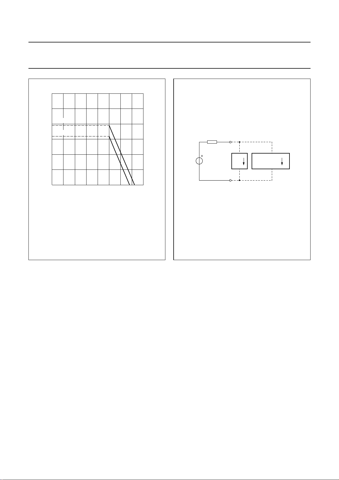
VCC≥ 2.5 V; VLN= 4.35 V at I
=20Ω.
R
SLPE
(1) This curve is valid when the receiving amplifier is not loaded.
(2) This curve is valid when the receiving amplifier is loaded;
V
o(rms)
12 43
= 15 mA; RCC= 619 Ω;
line
= 150 mV; RL= 150 Ω.
(2) (1)
MGL827
VCC (V)
handbook, halfpage
UBA2050(A); UBA2051(A;C)
V
R
CC0
CC
V
CC
GND
I
rec
PERIPHERAL
CIRCUITS
I
FCA130
P
Fig.8 Typical current IP available from VCC for
peripheral circuitry.
Regulated supply point (pin VDD)
The VDD regulator delivers a stabilized voltage to supply
the internal dialler and ringer parts and peripheral circuits
in transmission mode (nominal VLN) and in ringer mode
(VLN= 0 V). The maximum supply current for peripherals
is 1.9 mA in dialling mode (DTMF generator on) and
2.6 mA in speech mode (DTMF generator off). The supply
conditions in ringer and trickle (on-hook condition) modes
must not be disturbed by the peripheral supply currents.
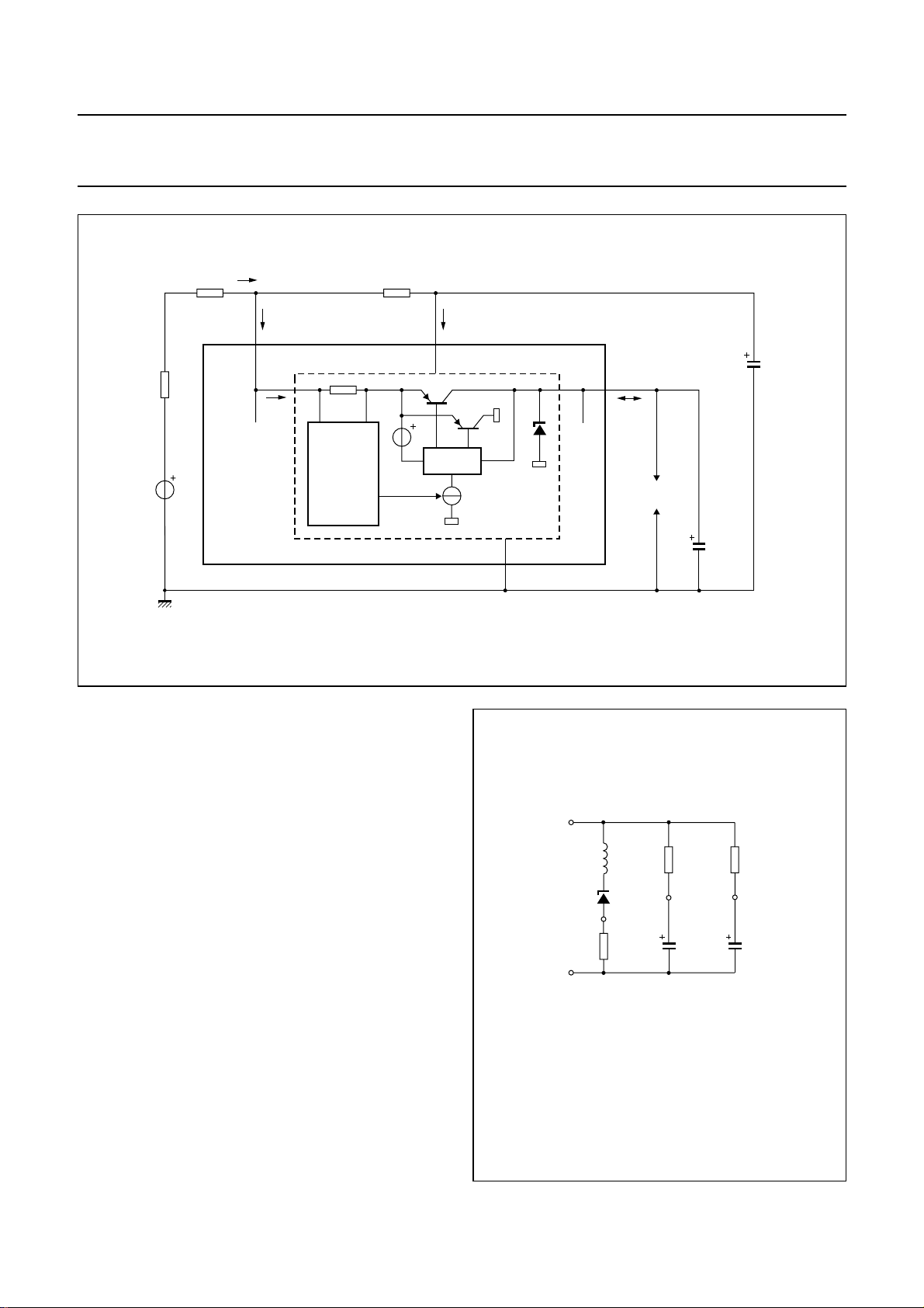
Theregulator (see Fig.7) consistsofa sense input circuitry
(pin LN), a current switch and a VDD output stabilizer
(pin VDD). VDD is decoupled by capacitor C
VDD
.
Theregulatorfunctiondepends on the transmission, ringer
and trickle modes as follows:
• Transmissionmode:Theregulatoroperatesasacurrent
source at the LN input; it takes a constant current of
= 4.5 mA (at nominal conditions) from pin LN.
I
SUP
The current switch reduces the distortion on the line at
large signal swings.
Fig.9 VCC used as supply voltage for peripheral
circuits.
Output V
follows the DC voltage at pin LN (with
DD
typically 0.35 V difference) up to VDD= 3.3 V. The input
current of the regulator is constant while the output
(source) current is determined by the consumption of
the peripherals. The difference between input and
output current is shunted by the internal VDD stabilizer.
• Ringer mode: The regulator operates as a shunt
stabilizer to keep VDD at 3.3 V. The input voltage
VLNequals 0 V while the input current into pin VDD is
delivered by the ringing signal.
• Trickle mode: When VDD is below typically 2 V, the
regulator is inhibited. The current consumption of the
VDDregulator in trickle mode is very low to save most of
the trickle current for memory retention of the dialler and
ringer parts.
2000 May 19 10
Page 11
Philips Semiconductors Product specification
One-chip telephone ICs with speech,
dialler and ringer functions
handbook, full pagewidth
R
exch
V
exch
R
line
UBA205xx
I
line
LN
I
SUP
I
LN
SENSE
R
CC
I
CC
V
CC
SWITCH
VDD regulator
GND
UBA2050(A); UBA2051(A;C)
C
VCC
V
DD
I
DD
peripherals
C
VDD
220 µF
100 µF
Fig.10 VDD regulator configuration.
SET IMPEDANCE
In the audio frequency range, the dynamic impedance is
mainly determined by resistor RCC. The equivalent
impedance of the circuit is illustrated in Fig.11.
handbook, halfpage
GND
LN
SLPE
L
EQ
V
ref
R
SLPE
20 Ω
FCA131
R
P
REG V
C
REG
4.7 µF
FCA132
R
CC
619 Ω
CC
C
VCC
100 µF
2000 May 19 11
LEQ=C
Internal resistance RP= 17.5 kΩ.
REG
× R
SLPE
× Rp.
Fig.11 Equivalent impedance between
LN and GND.
Page 12
Philips Semiconductors Product specification
One-chip telephone ICs with speech,
dialler and ringer functions
TRANSMIT STAGES
Microphone signal amplification (pins MIC+ and MIC−)
The UBA205xx has symmetrical microphone inputs. The
input impedance between pins MIC+ and MIC− is 64 kΩ
(2 × 32 kΩ).
handbook, full pagewidth
(2)
MIC−
(1)
MIC+
UBA2050(A); UBA2051(A;C)
In speech mode, the voltage gain from pins MIC+ and
MIC− to pin LN is set at 44.2 dB at 600 Ω line load.
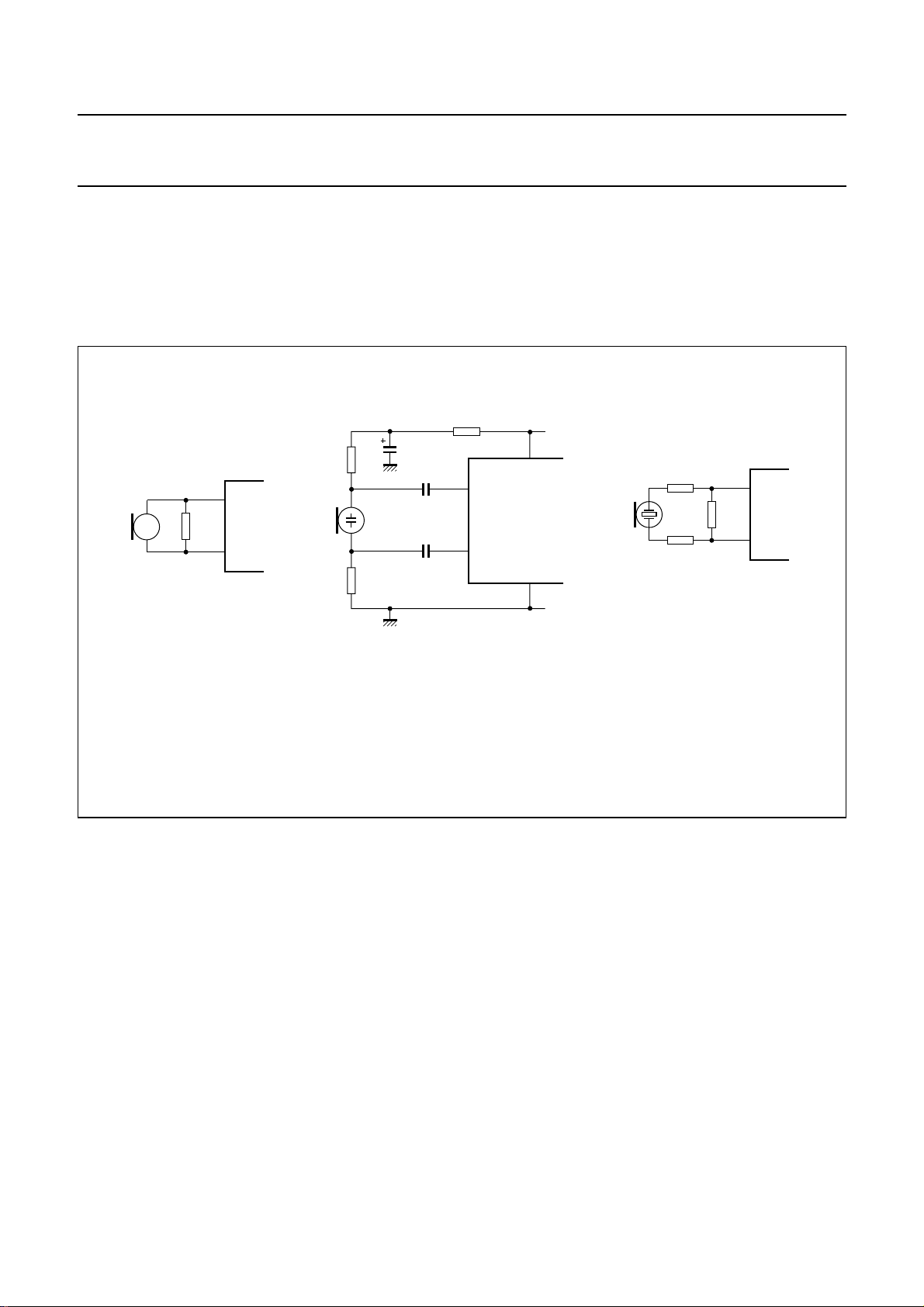
Microphone arrangements are illustrated in Fig.12.
Automatic gain control is provided on this amplifier for line
loss compensation.
V
CC
MIC−
MIC+
GND
MIC−
MIC+
MGT052
a. Magnetic or dynamic microphone. b. Electret microphone. c. Piezoelectric microphone.
(1) This resistor may be connected to reduce the terminating impedance.
(2) Extra decoupling capacitor for the microphone supply.
Fig.12 Microphone arrangements.
DTMF amplification (pin DTMF)
When the DTMF amplifier is enabled, dialling tones may
be sent on the line. These tones are generated at
pin MDY/TONE and their amplitude can be adjusted by
means of an attenuator and filter network (see Fig.35)
before being applied to the DTMF amplifier at pin DTMF.
The automatic gain control has no effect on the DTMF
amplifier.
RECEIVE STAGES
The receive part consists of a receive amplifier and an
earpiece amplifier.
Thesetonesarealso sent to the receive output RX atalow
level (confidence tone).
The UBA205xx has an asymmetrical DTMF input. The
input impedance between pins DTMF and GND is 20 kΩ.
The voltage gain from pin DTMF to pin LN is set at 26 dB
at 600 Ω line load. The DC voltage between pins DTMF
and GND is 0 V. So, when an external attenuator/filter
network is used, there is no need for a second decoupling
capacitor.
Receive amplifier (pins IR and RX)
The receive amplifier transfers the received signal from
input IR to output RX. The input impedance between
pins IR and GND is 20 kΩ.
The voltage gain from pin IR to pin RX is fixed at 33.4 dB.
The RX output is intended to drive high ohmic (real) loads.
Automatic gain control is provided on thereceive amplifier.
2000 May 19 12
Page 13
Philips Semiconductors Product specification
One-chip telephone ICs with speech,
dialler and ringer functions
Earpiece amplifier (pins GAR and QR)
The earpiece amplifier is an operational amplifier having
its output QR and inverting input GAR available. It can be
used in conjunction with two resistors to get some extra
gain or attenuation.
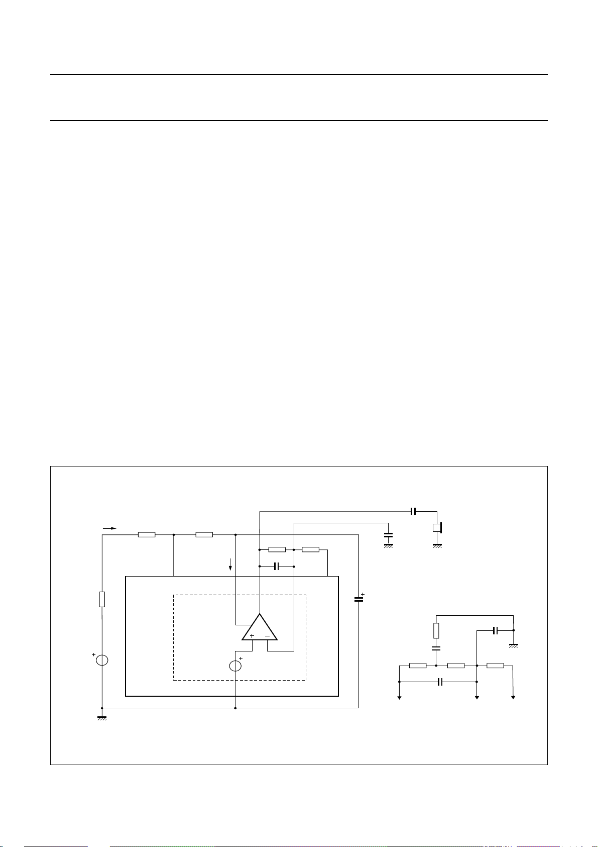
Arrangements of the receive and earpiece amplifier are
illustrated in Fig.13. Earpiece connections are shown
in Fig.14.
In the basic configuration (see Fig.13), output RX drives
the earpiece amplifier by means of RE1 connected
between pins RX and the inverting input GAR. Feedback
resistor R
between pins QR and GAR. Output QR drives the
earpiece via a series capacitor C
The gain of the earpiece amplifier (from RX to QR) can be
set between +12 and −14 dB by means of resistor R
The preferred value of RE1 is 100 kΩ.
The earpiece amplifier offers a gain boost facility relative
to the initial gain. Resistor R
network of R
Cgb as shown in Fig.13.
of the earpiece amplifier is connected
GAR
.
ear
has to be replaced by the
GAR
GAR1,RGAR2
and Rgb and a series capacitor
GAR
UBA2050(A); UBA2051(A;C)
V
= ∞.
QR
---------V
RX
The initial gain is defined by:
which corresponds to R
gb
The gain boost is realised by a defined value of Rgband is
defined by:
+
V
QR
---------V
RX
R
GAR1RGAR2
--------------------------------------- -
R
E1
External capacitors C
QR and GAR) and C
GAR
GARS
+
×–=
1
(connected between pins
(connected between pins GAR
and GND) ensure stability. The capacitor C
first-order low-pass filter. The cut-off frequency
corresponds to the time constant C
of C
.
must be 10 times the value of C
GARS
stability.
The output voltages of the earpiece amplifier and the
DTMF amplifier are specified for continuous wave drive.
The maximum output voltage swing depends on the
DC line voltage VLN, the DC resistance RCC of the
set-impedance network between pins LN and VCC, the
current consumption ICCand IPfrom pin VCCand the load
impedance at pin QR.
R
GAR1RGAR2
–=
--------------------------------------- -
R
----------------------------------------- R
------------------------------------------
×
GAR1RGAR2
+
GAR1RGAR2
R
gb
GAR
× R
GAR
GAR
GAR
+
R
E1
provides a
. The value
to ensure
handbook, full pagewidth
V
R
exch
exch
I
line
UBA205xx
R
line
R
CC
EARPIECE
AMPLIFIER
R
GAR
C
CC
0.5V
CC
GAR
QRLN GAR
I
CC
V
GND
Fig.13 Receive and earpiece amplifier configuration.
2000 May 19 13
C
ear
C
R
E1
RX
C
100 µF
GARS
VCC
R
GAR2
Addition for gain boost of earpiece amplifier
earpiece
R
gb
C
gb
R
GAR1
C
GAR
C
GARS
R
E1
RXGARQR
FCA133
Page 14

Philips Semiconductors Product specification
One-chip telephone ICs with speech,
dialler and ringer functions
handbook, full pagewidth
QR QR QR
a. Dynamic earpiece.
b. Magnetic earpiece.
UBA2050(A); UBA2051(A;C)
(1) (2)
GNDGNDGND
MGT051
c. Piezoelectric earpiece.
(1) This resistor may be connected to prevent distortion due to the inductive load.
(2) This resistor is required to increase the phase margin due to the capacitive load.
Fig.14 Earpiece connections.
2000 May 19 14
Page 15
Philips Semiconductors Product specification
One-chip telephone ICs with speech,
dialler and ringer functions
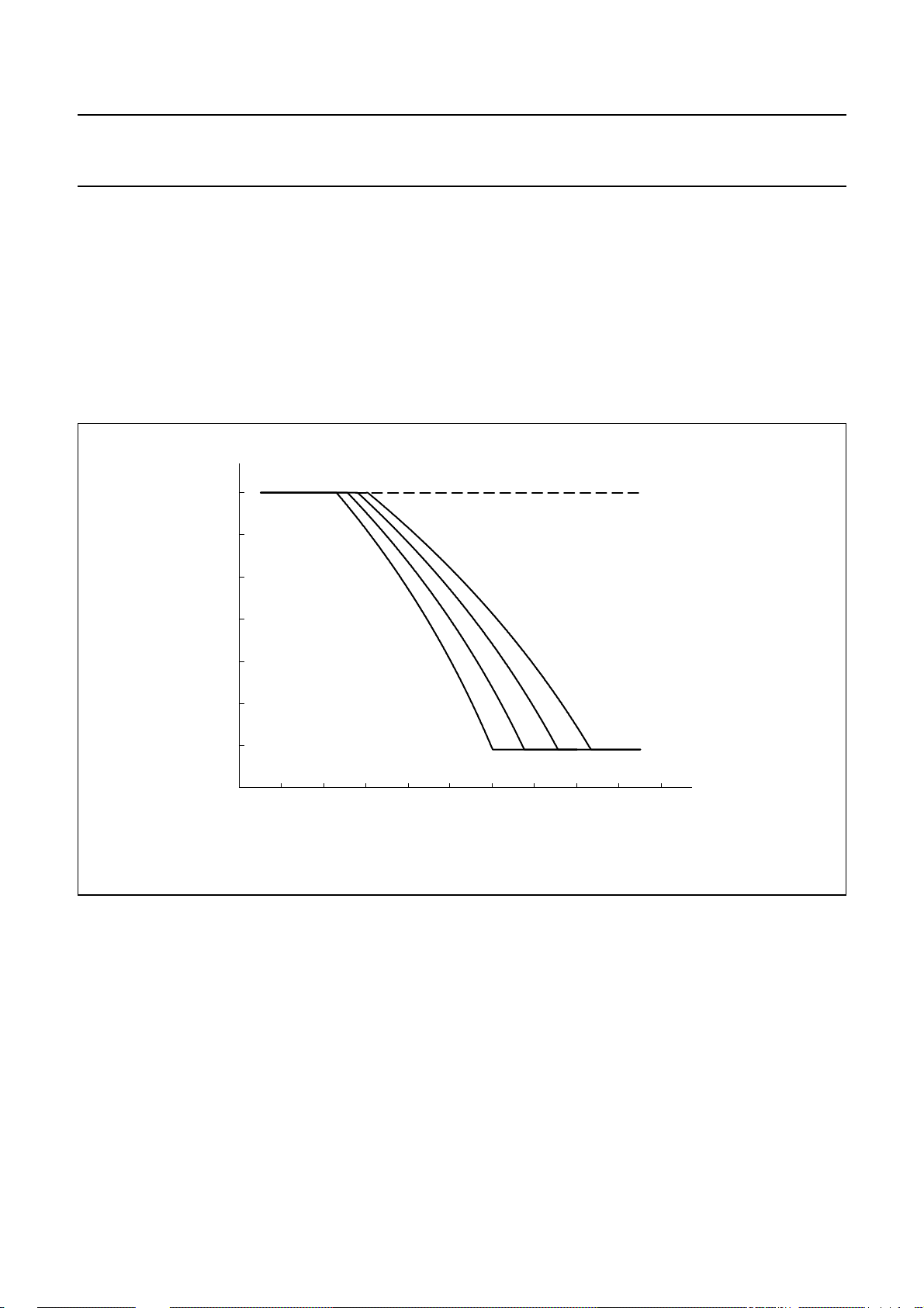
AUTOMATIC GAIN CONTROL (PIN AGC)
The UBA205xx performs automatic line loss
compensation. The automatic gain control varies the gain
of the microphone amplifier and the gain of the receive
amplifier in accordance with the DC line current.
The control range is 6.0 dB. This corresponds
approximately to the lossfor a cable length of 5 km withan
0.5 mm diameter twisted copper-pair, a DC resistance of
176 Ω/km and an average attenuation of 1.2 dB/km).
handbook, full pagewidth
0
∆G
v
(dB)
−2
UBA2050(A); UBA2051(A;C)
The IC can be used with different configurations of
exchange supply voltage andfeeding bridge resistanceby
connecting an external resistor R
and GND (see Fig.15). This resistor enables the I
I
line currents to be increased (the ratio between I
stop
and I
is not affected by the resistor).
stop
The AGC function is disabled when pin AGC is left
open-circuit.
∞
R
=
AGC
between pins AGC
AGC
start
and
start
−4
−6
0 10 20 30 kΩ
I
line
Fig.15 Variation of gain as a function of line current with R
(mA)
as parameter.
AGC
10080604020 90705030100
MGT049
2000 May 19 15
Page 16
Philips Semiconductors Product specification
One-chip telephone ICs with speech,
dialler and ringer functions
SIDETONE SUPPRESSION
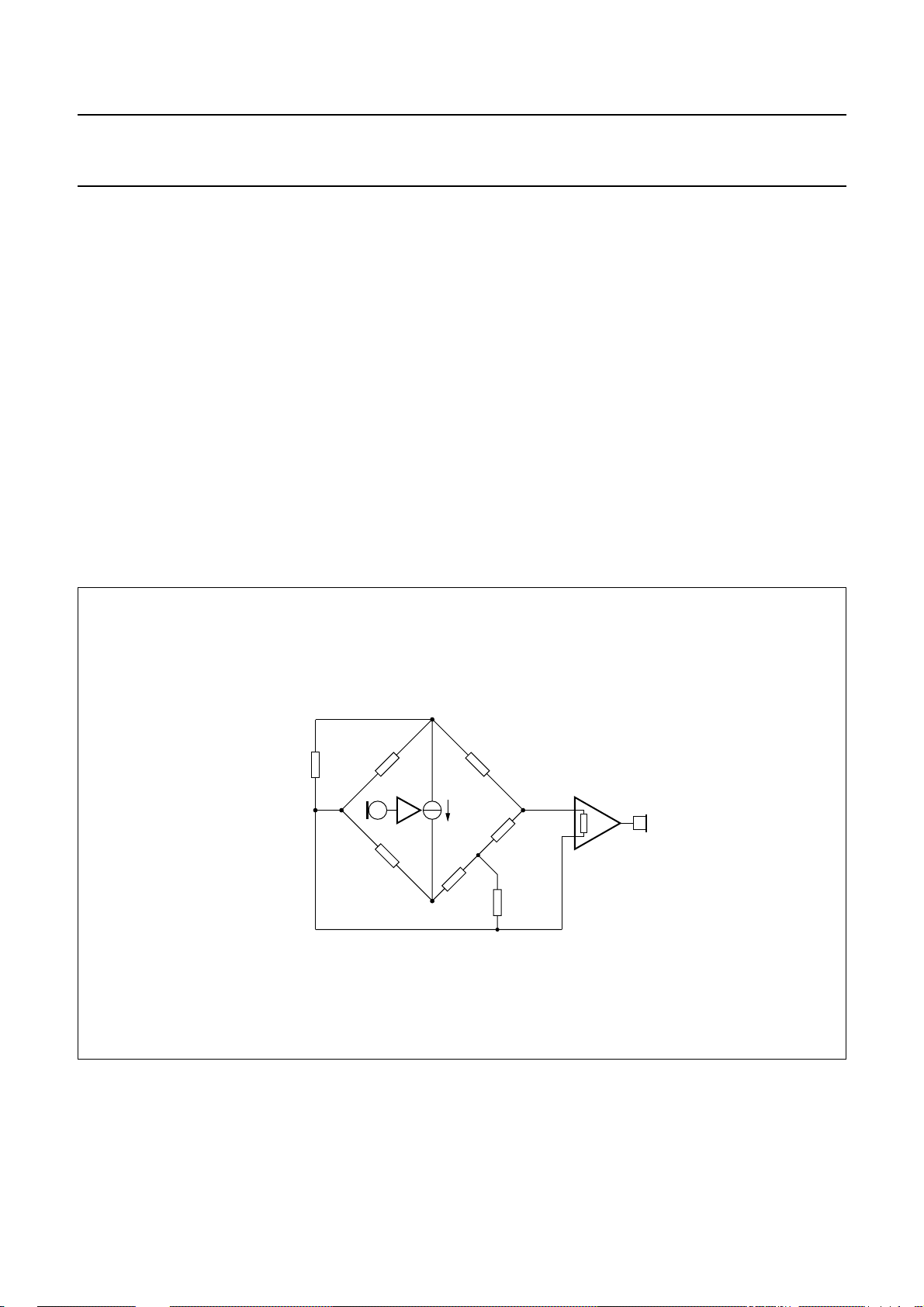
The anti-sidetone network for the UBA205xx, comprising
RCCin parallel with Z
line,Rast1,Rast2,Rast3,RSLPE
(see Fig.16), suppresses the transmitted signal in the
earpiece. Maximum compensation is obtained when the
following conditions are fulfilled:
R
× R
k
Z
SLPE
=
bal
ast1=RCC
R
-----------------------------------------------------------
=k×Z
R
ast2
R
ast1RSLPE
line
× (R
+()×
ast3RSLPE
×
ast2+Rast3
)
The scale factor k is chosen to meet the compatibility with
a standard capacitor from the E6 or E12 range for Z
In practice, Z
the line length. Therefore, the value of Z
varies considerably with the line type and
line
bal
chosenfor an average linelength, which gives satisfactory
sidetone suppression with short and long lines.
and Z
should be
bal
bal
.
UBA2050(A); UBA2051(A;C)
The suppression also depends on the accuracy of the
match between Z
line.
The anti-sidetone network for the UBA205xx attenuates
the received signal from the line by 32 dB before it enters
the receive stage. The attenuation is almost constant over
the whole audio frequency range.
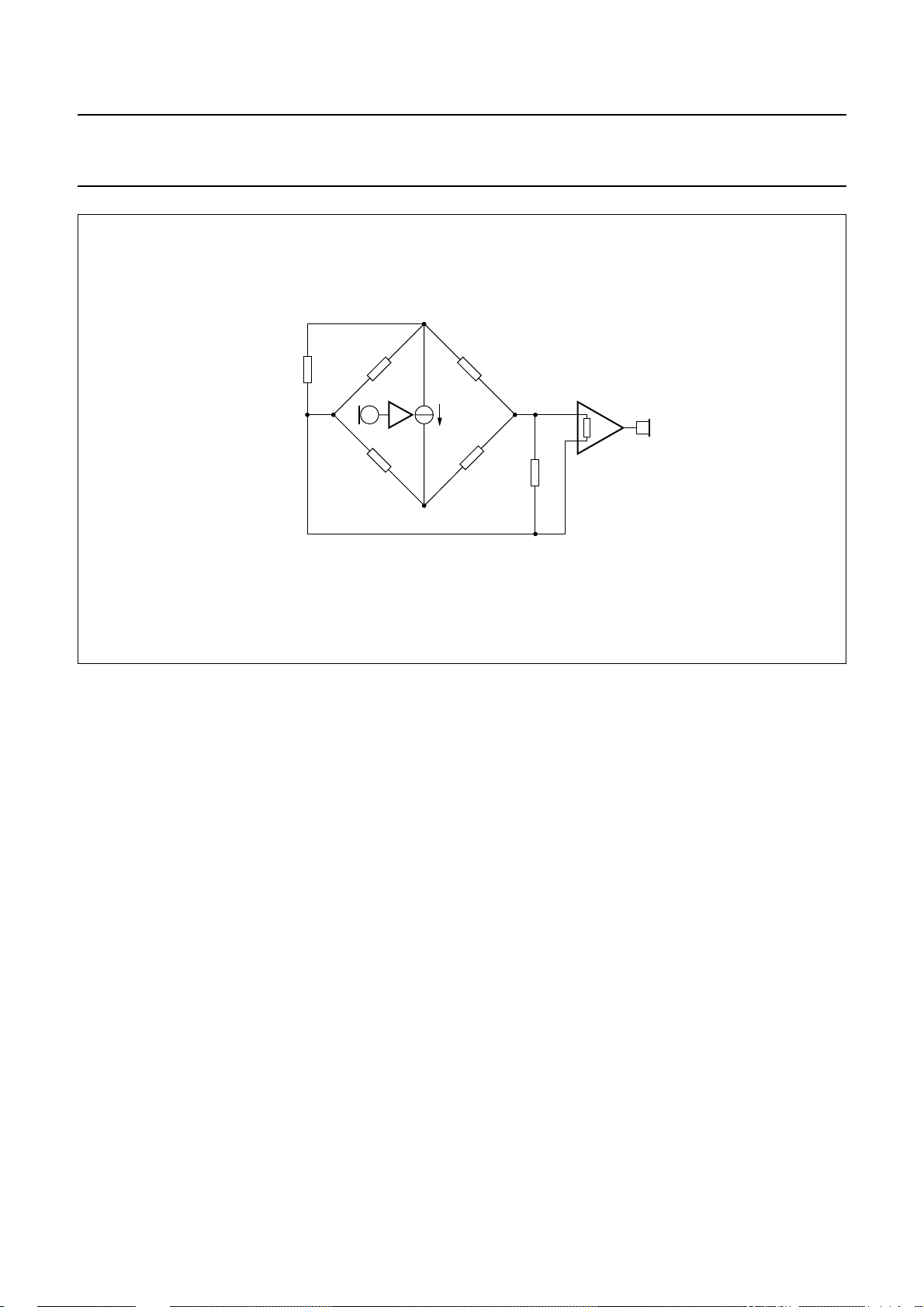
A Wheatstone bridge configuration (see Fig.17) may also
be used.
More information on the balancing of an anti-sidetone
bridge can be obtained in our publication
Handbook for Wired Telecom Systems, IC03b”
and the impedance of the average
bal
“Application
.
handbook, full pagewidth
LN
Z
line
GND
R
SLPE
R
CC
SLPE
R
ast1
I
m
R
ast3
IR
Z
R
ast2
Z
bal
MGT046
ir
Fig.16 Equivalent circuit of UBA205xx anti-sidetone bridge.
2000 May 19 16
Page 17
Philips Semiconductors Product specification
One-chip telephone ICs with speech,
dialler and ringer functions
handbook, full pagewidth
R
R
CC
SLPE
SLPE
Z
line
GND
LN
UBA2050(A); UBA2051(A;C)
Z
bal
I
m
IR
Z
ir
R
ast1
R
A
MGT047
Fig.17 Equivalent circuit of an anti-sidetone network in a Wheatstone bridge configuration.
Dialler and ringer parts
SUPPLY VOLTAGE (PIN VDD)
The power supply must be maintained for repertory
memory retention (standby supply voltage) and may drop
down to 1.0 V, being the minimum value of the memory
retention voltage V
. Applying a large capacitor across
MR
the supply terminals can retain the memory when power
connections are broken.
The minimum operating voltage is 2.0 V (the Power-on
reset voltage V
has its maximum value). Below this
POR
value, the internal Power-on reset disables the IC.
A memory integrity check is performed at each start-up.
In the event of a failing check, the memory is cleared.
SCILLATOR (PIN XTAL)
O
The UBA205xx uses an on-chip oscillator as the master
timing source. It needs to be completed by an external
3.579545 MHz quartz crystal or ceramic resonator
connected between pins XTAL and GND. When using an
external ceramic resonator, additional components may
be required depending upon the ceramic resonator
specifications (refer to the product type specification).
By connecting a capacitor with a value of a few pico-farad
in parallel with the resonator, the oscillator frequency can
be decreased. By connecting a capacitor with a value of a
few ten pico-farad in series with the resonator, the
oscillator frequency can beincreased. The oscillatorstarts
when V
reaches the operating voltage level V
DD
POR
and
pin CE/FDI or pin CE/CSI goes HIGH.
Recommended resonator types: Murata
CSA 3.58MG300FGA or CSAC 3.58MGC300FGA.
2000 May 19 17
Page 18
Philips Semiconductors Product specification
One-chip telephone ICs with speech,
dialler and ringer functions
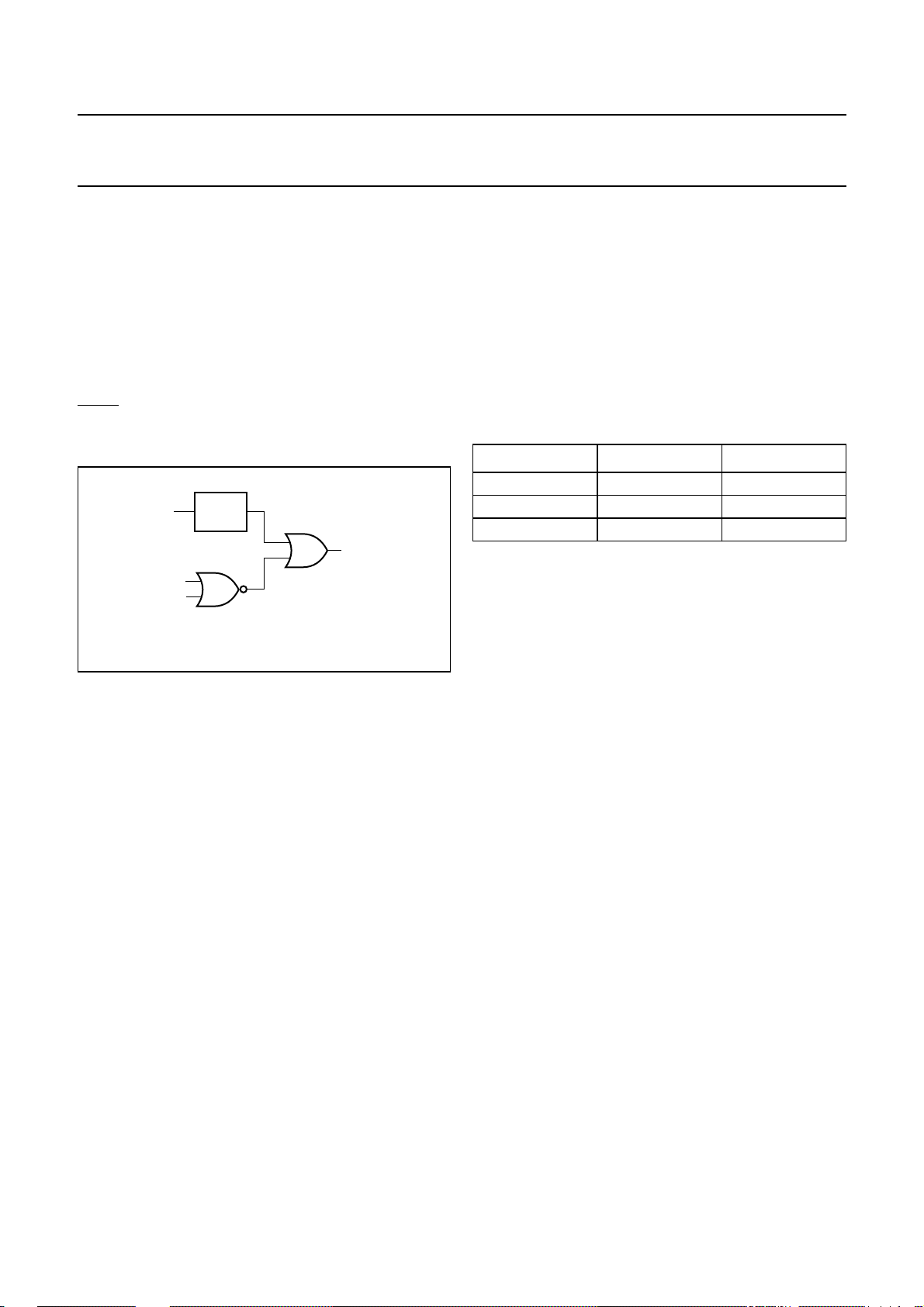
INTERNAL RESET CIRCUIT (PINS CE/FDI AND CE/CSI)
A reset signal is internally generated to initialize the
UBA205xx as follows (see Fig.18):
• Bythe on-chip Power-On Reset (POR) circuitas long as
VDDis lower than V
• When the voltage on pin CE/CSI and on pin CE/FDI are
both LOW for a time greater than the reset delay
time tRD.
When reset conditions are fulfilled, pins MDY/TONE and
DP/FL are set to high-impedance; pins DMO, KT, LED,
R1 to R4 and C1 to C4 are set to LOW.
handbook, halfpage
V
DD
CE/CSI
CE/FDI
POR
POR
NOR
OR
reset
MGM334
UBA2050(A); UBA2051(A;C)
C
HIP ENABLE/CRADLE SWITCH INPUT (PIN CE/CSI)
To distinguish between different operating states an extra
CE/CSIinput is used. Comparabletothe CE/FDI input, the
CE/CSI activates the dialler part. From that moment the
dialler part polls this input and the CE/FDI input regularly
for line power breaks during on-line states. When pins
CE/CSI and CE/FDI are set LOW for a time greater than
tRD, the standby state is entered. Pin CE/CSI is set HIGH
during the off-hook situation (basic application). The basic
states are shown in Table 2.
Table 2 UBA205xx basic states
INPUT CE/CSI INPUT CE/FDI STATE
LOW LOW standby
HIGH X; note 1 handset
LOW HIGH ringer; note 2
Notes
1. Don’t care.
2. AC signal at pin CE/FDI.
Fig.18 Internal reset.
HIP ENABLE AND FREQUENCY DISCRIMINATOR INPUT
C
(PIN CE/FDI)
This input is used to activate and initialize part of the
system. This pin together with the pin CE/CSI determines
which mode to enter (see Table 2) and detects line power
breaks during on-line states. To prevent the dialler from
reacting on voltage disturbances on the telephone line, a
time-out is active. The dialler returns to the standby state
if the voltage on both pins CE/CSI and CE/FDI is LOW for
a time greater than tRD.
Inthe exchange, several AC signalscan be superimposed
on the DC signal, e.g. dialling tone, busy tone,
disturbances (such as line power breaks) and ringer
signal. The ringer signal is evaluated and checked if its
frequency is above a specified ringer frequency f
ring
. It is
assumed that the frequency at pin CE/FDI is the same as
the ringer frequency present on the telephone line.
The signal at this pin is half-wave rectified so that the
dialler can easily detect zero-crossing, especially at high
frequency.
During switching (on-hook/off-hook and pulse dialling) this
pin is protected by its ESD diodes. The maximum input
current on these diodes should be below 1 mA.
During switching (on-hook/off-hook and pulse dialling) this
pin is protected by its ESD diodes. The maximum input
current on these diodes should be below 1 mA.
R
INGER MELODY (PIN MDY/TONE)
When an incoming ringer signal at pin CE/FDI is valid, the
UBA205xx starts generating a melody via the MDY/TONE
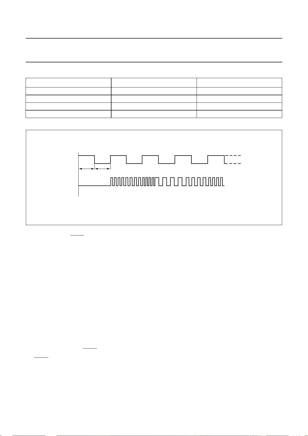
output ringer hardware (see Fig.35). The signal at
pin MDY/TONE is a square wave signal (see Fig.19).
This melody follows the cadence of the ringer signal. Both
the melody and the volume can be selected via the
keyboard.
The melody frequencies and the duration are given in
Table 3. Table 8 shows how a melody can be selected by
pressing a key during ringing. The melody setting will be
stored in the memory.
The volume of the ringer circuit can be controlled by
changing the amplitude of the square wave. The voltage
level at pin MDY/TONE can be changed as shown in
Table 9. The volume setting will be stored in the memory.
MDY/TONE is a push-pull output. MDY/TONE is
high-impedance when VDD<V
POR
.
2000 May 19 18
Page 19
Philips Semiconductors Product specification
One-chip telephone ICs with speech,
UBA2050(A); UBA2051(A;C)
dialler and ringer functions
Table 3 Ringer melodies
NAME FREQUENCIES (Hz) DURATION (ms)
Bell 1 (default) 770+ 943 + 1341 28 + 28 + 28
Bell 2 852 + 943 + 1206 28 + 28 + 28
Bell 3 943 + 1206 + 1341 28 + 28 + 28
Bell 4 1206 + 1341 + 1482 28 + 28 + 28
handbook, full pagewidth
CE/FDI
sync
sample
MDY/TONE
time
time
V
DD
GND
MGT050
Fig.19 Ringer frequency detection.
PULSE DIALLER (PINS DP/FL, DMO AND LED)
The pulse dialling system uses line current interruptions to
signal the digits dialled to the exchange. The number of
line current interruptions corresponds to the digit dialled
except for the digit [0] which is characterized by
10 interruptions. After each digit there is an inter-digit
pause time (t
idp
).
When dialling, the transmission part is muted.
The [∗/T] key definition, the dialling mode, the make/break
ratio, repetition rate (pulse dialling), the flash time and the
access pause time depend on the resistor options: MMS,
PTS, MBS, PPS, FTSA, FTSB and APT (see Fig.25 and
Table 7).
Valid keys are the digits [0] to [9], [R], [LNR/P], [P → T]
and [∗/T] (when MMS resistor option is off).
To allow start-up from C
discharged, no ESD diode is
VDD
implemented between pin DP/FL and pin VDD.
Pin DP/FL is an open-drain output and is set HIGH (via an
external pull-up resistor) when VDD<V
POR
.
Pin DMO of the UBA205x is used to enable external
hardware (see Fig.37) which decreases the DC voltage
overtheA and Bnetwork exchange terminals during pulse
dialling. Several countries require this feature. Pin DMOis
a push-pull output and is LOW when VDD<V
POR
.
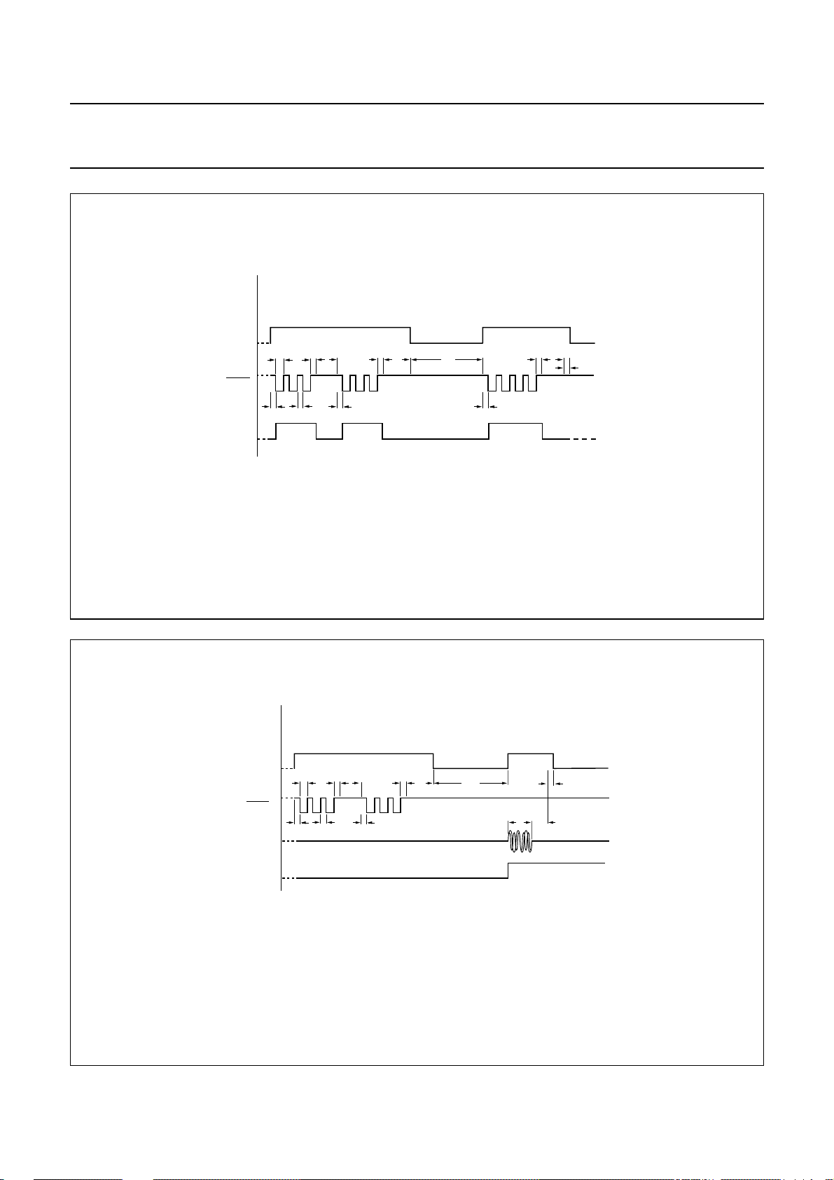
Figure 20 shows thetiming diagram in pulse dialling mode
for the UBA205x when keys [3], [3], [LNR/P] and [4] are
pressed.
Figure 20 is also valid for the UBA2051C, with the
exception of the DMO signal.
In pulse dialling mode, pin LED of the UBA205xA is set
LOW after off-hook and becomes HIGH when the first
DTMF code is sent after switching over to DTMF dialling.
Pin LED is a push-pull output and is LOW when
VDD<V
POR
.
Figure 21 shows thetiming diagram in pulse dialling mode
for the UBA205xA when keys [3], [3], [P → T] and [4] are
pressed.
2000 May 19 19
Page 20
Philips Semiconductors Product specification
One-chip telephone ICs with speech,
dialler and ringer functions
handbook, full pagewidth
[3].........[3]......... [LNR/P].........[4]
KEYS
internal
tb= break time.
tm= make time.
t
= interdigit pause time.
idp
MUTE
DP/FL
DMO
t
t
pdp
tap= access pause time.
t
= mute holdover time.
mho
t
= pre-digit pause.
pdp
t
t
idp
m
b
t
t
m
pdp
UBA2050(A); UBA2051(A;C)
t
t
idp
m
t
ap
t
pdp
t
t
m
idp
t
mho
MGU139
handbook, full pagewidth
tb= break time.
tm= make time.
t
= interdigit pause time.
idp
tap= access pause time.
Fig.20 Timing diagram in pulse dialling mode for the UBA205x.
t
pdp
...................
t
t
idp
m
t
ap
mho
t
t
t
p
KEYS
internal
MUTE
DP/FL
MDY/TONE
LED
t
mho
t
pdp
tt= burst time.
tp= pause time.
....[3].............. [3].........[P->T] [4]
t
b
t
pdp
= mute holdover time.
= pre-digit pause.
t
t
idp t
m
t
m
MGU140
Fig.21 Timing diagram in pulse dialling mode for the UBA205xA.
2000 May 19 20
Page 21
Philips Semiconductors Product specification
One-chip telephone ICs with speech,
dialler and ringer functions
TONE DIALLER (PINS MDY/TONE AND LED)
The digits are transmitted as two simultaneously
generated tones: the Dual-Tone Multi-Frequency (DTMF)
system. These dual tones which are provided at the
MDY/TONEoutputareinternally generated with two digital
sine wave synthesizers together with digital-to-analog
converters. Their amplitudes are precisely scaled
according to a band gap voltage reference. This ensures
tone output levels independent of the supply voltage and
temperature. The two sine waves are summed and then
filtered by an on-chip switched capacitor filter, followed by
an active RC low-pass filter. These guarantee that all
DTMF tones generated fulfil the CEPT CS203
recommendations with respect to amplitude, frequency
deviation, total harmonic distortion and suppression of
unwanted frequency components. Tone digits are
separated by a pause time (tp).
At dialling, the DTMF input of the transmission part is
enabled while the microphoneand receive amplifierinputs
are disabled. The signal at the DTMF input is sent to the
receive output at a low level [see Section “DTMF
amplification (pin DTMF)”].
UBA2050(A); UBA2051(A;C)
Valid keys are the digits [0] to [9], [∗/T], [#], [R], [LNR/P]
and [P → T].
The dialling mode, the flash time and the access pause
time depend on the resistor options: PTS, FTSA, FTSB
and APT (see Fig.25 and Table 7).
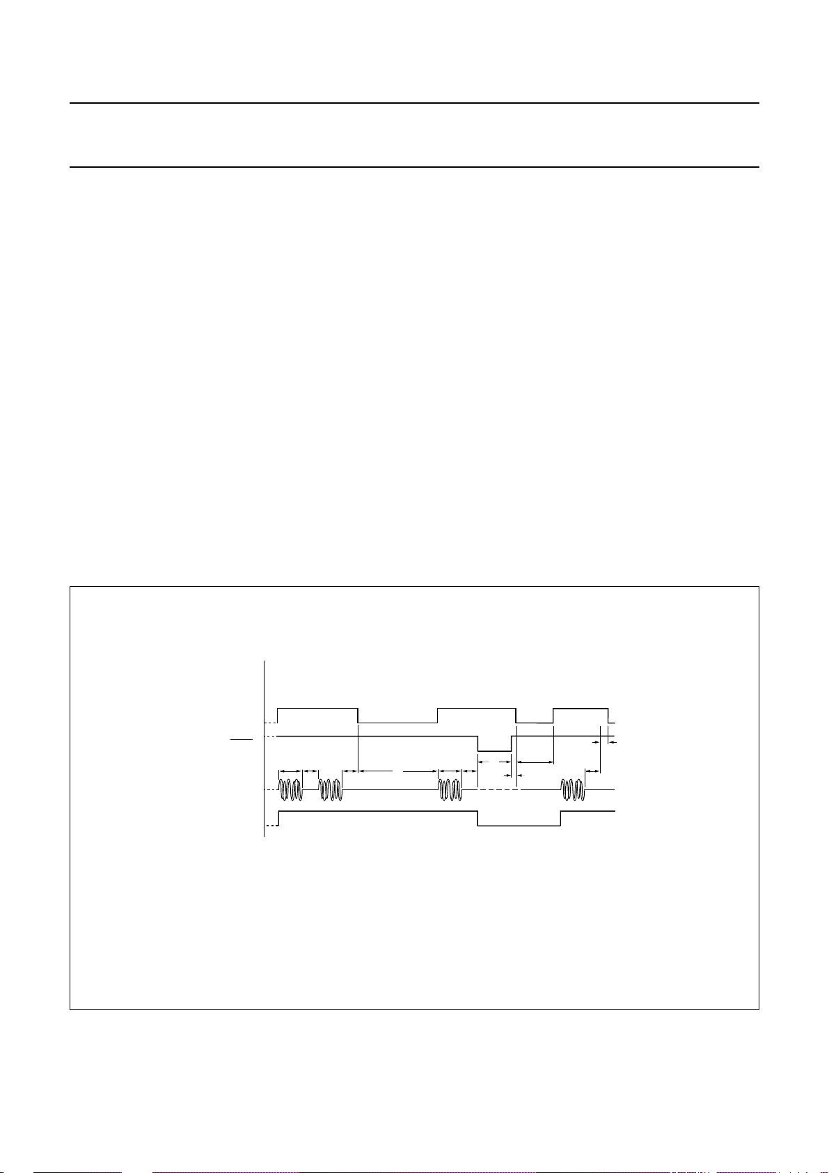
Figure 22 shows the timing diagram in tone dialling mode
when keys [3], [3], [LNR/P], [4], [R] and [2] are pressed.
In DTMF dialling mode, pin LED of the UBA205xA is set
LOW after the hook-switch changes to off-hook and
becomes HIGH as soon as a key is pressed and the first
DTMF code is sent. Pin LED is a push-pull output and is
LOW when VDD<V
The DTMF standard frequencies are implemented as
shown in Table 4.
POR
.
handbook, full pagewidth
tt= burst time.
tp= pause time.
tap= access pause time.
tfl= flash time.
t
= interflash pause time.
ifp
KEYS
internal
MUTE
DP/FL
MDY/TONE
LED
......
.....[3]
(1)
..............
[3]
t
t
p
t
t
mho
t
fho
Note: themaximumtone burst and pause times areequalto the real key press/release time.
(1) pin LED only available inUBA205xA.
.......................
[LNR/P]
t
p
= mute holdover time.
= flash holdover time.
t
ap
..............
[4]
t
t
Fig.22 Timing diagram in tone dialling mode.
.......................
[R]
t
fl
t
p
t
fho
high impedance
[2]
t
t
ifp
mho
t
p
MGU141
2000 May 19 21
Page 22
Philips Semiconductors Product specification
One-chip telephone ICs with speech,
dialler and ringer functions
Table 4 DTMF standard frequencies and their implementation
DTMF FREQUENCY (Hz)
697 697.90 0.13 0.90
770 770.46 0.06 0.46
852 850.45 −0.18 −1.55
941 943.23 0.24 2.23
1209 1206.45 −0.21 −2.55
1336 1341.66 0.42 5.66
1477 1482.21 0.35 5.21
Note
1. Assuming f
= 3.579545 MHz.
xtal
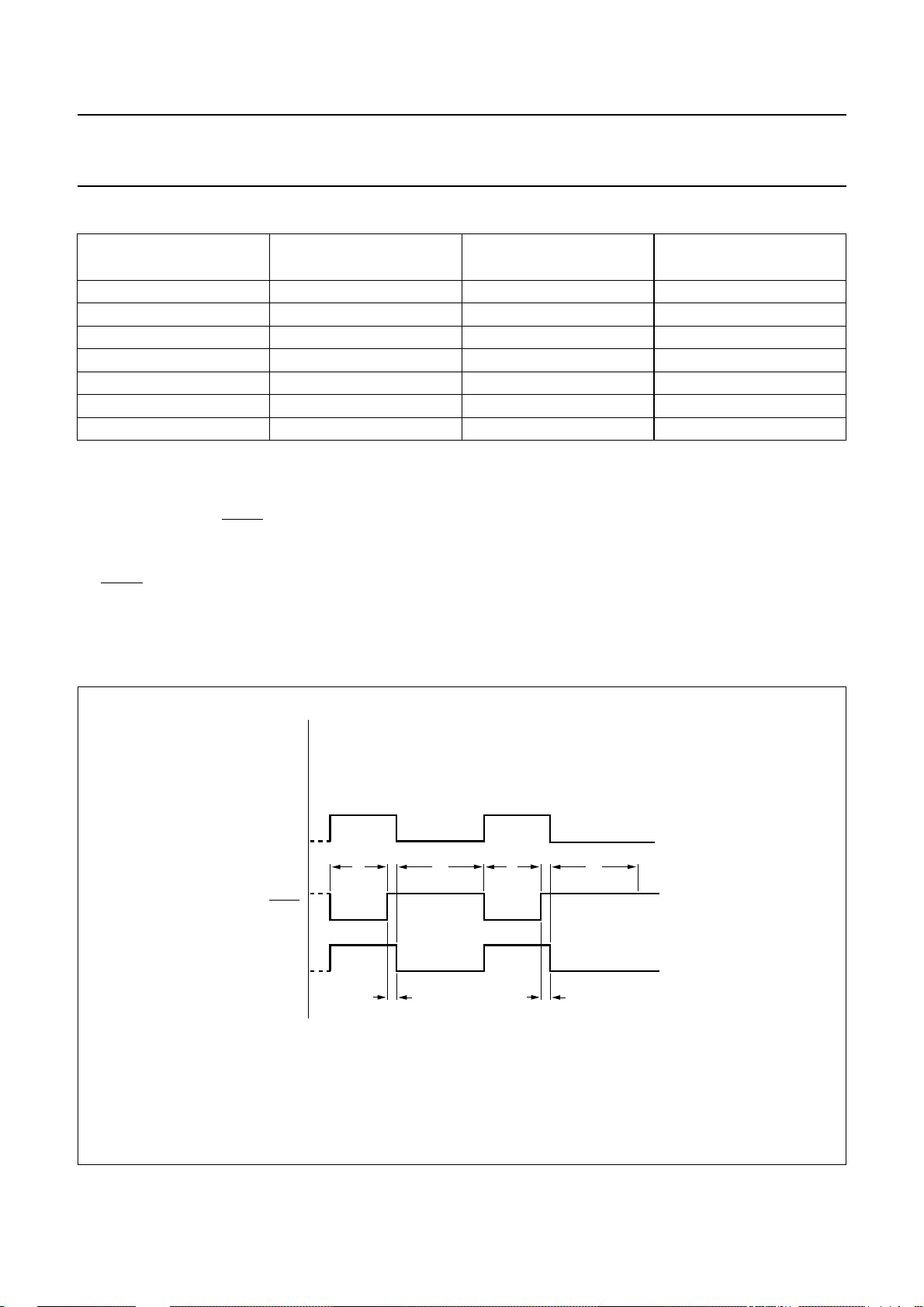
FLASH FUNCTION (PINS DP/FL AND DMO)
Pressing the flash function key [R] results in a calibrated
pulsewhichdrivestheelectronicline current interrupter via
pin DP/FL. The DMO output is also activated during pulse
production (see Fig.23). After a flash pulse, an interflash
pause time t
of 800 ms is inserted to recover the power
ifp
supply for the dialler part.
FREQUENCY AT
MDY/TONE (Hz)
(1)
The duration of the flash time depends on the resistor
options FTSA and FTSB (see Fig.25 and Table 7).
During tfl+t
UBA2050(A); UBA2051(A;C)
DEVIATION (%) DEVIATION (Hz)
, the reset delay time is inhibited.
fho
handbook, full pagewidth
(1) pin DMO available only on UBA205x.
tfl= flash time.
t
= flash holdover time.
fho
t
= interflash pause time.
ifp
KEYS
internal
MUTE
DP/FL
DMO
[R] ............................[R]
t
fl
(1)
t
fho
..........................
t
ifp
t
t
fho
fl
t
ifp
MGU142
Fig.23 Flash timing diagram.
2000 May 19 22
Page 23
Philips Semiconductors Product specification
One-chip telephone ICs with speech,
dialler and ringer functions
KEYBOARD DETECTOR (PINS C1 TO C4 AND R1 TO R4)
The pins are directly connected to a traditional single
contact keyboard. The keyboard is normally static with
outputs R1 to R4 at LOW level and inputs C1 to C4 with
internal pull-up resistors. When any key is pressed,
scanning is done to detect which key has been pressed.
A second key entry will be valid after having released the
first key entry. Simultaneously pressing several keys will
result in no action.
handbook, full pagewidth
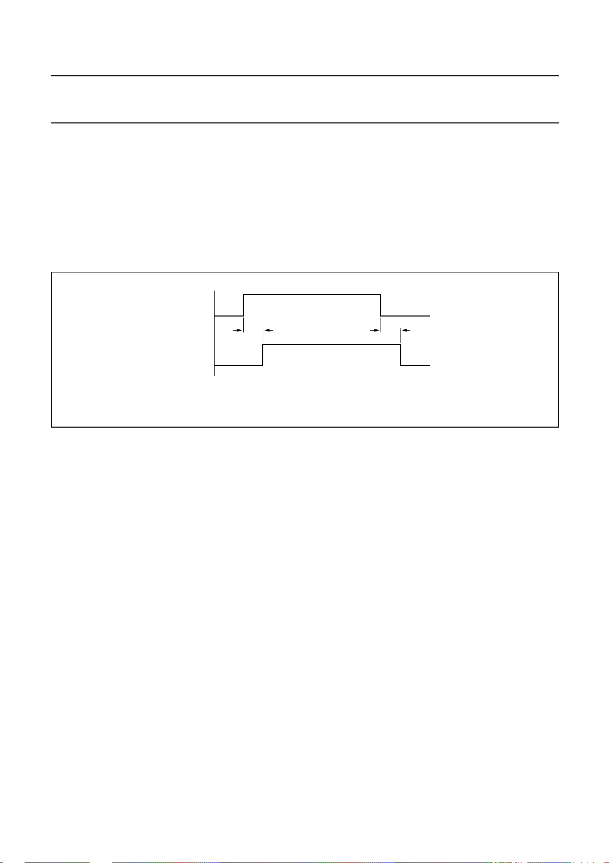
tdd= depress debounce time.
trd= release debounce time.
key entry
key valid
t
dd
UBA2050(A); UBA2051(A;C)
A key entry becomes valid when the depress debounce
time tdd has elapsed (see Fig.24). After the release of a
valid key, the scanning is frozen when the release
debounce time trd has elapsed.
The pins R1 to R4 are LOW and pull-down resistors
replace pull-up resistors at pins C1 to C4 when
VDD<V
POR
.
t
rd
MGM341
Fig.24 Timing diagram debouncing.
2000 May 19 23
Page 24
Philips Semiconductors Product specification
One-chip telephone ICs with speech,
UBA2050(A); UBA2051(A;C)
dialler and ringer functions
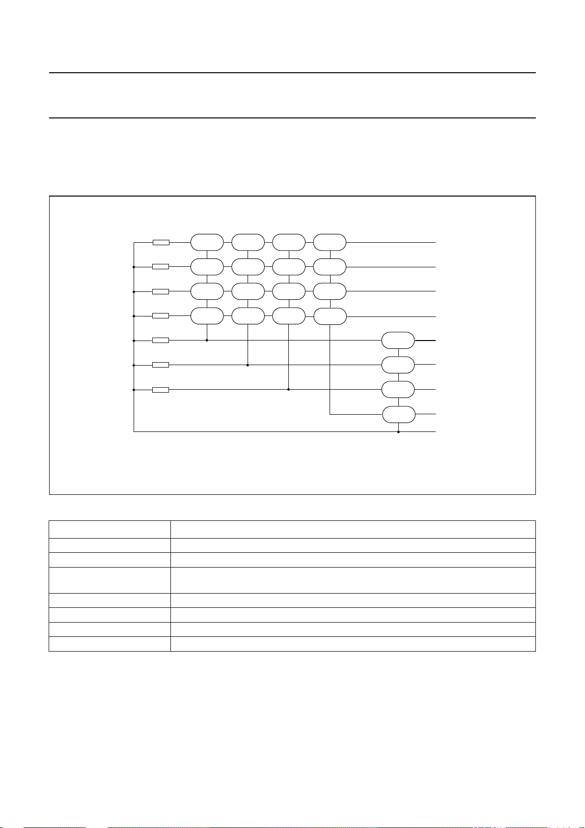
Keyboard structure
The UBA205xx supports the keyboard structure given in Fig.25. Pin C4 is not available in the UBA2050x.
For key definitions, see Table 5.
handbook, full pagewidth
MBS
APT
PPS
PTS
MMS
FTSA
1
4
7
/T
*
23
5
8
0
6
9
#
MEM
M1
M2
M3
P->T
LNR/P
R1
R2
R3
R4
C1
C2
FTSB
R
STORE
C3
C4
GND
FCA139
Fig.25 Keyboard structure.
Table 5 Key definitions
KEYS DEFINITION
[0] to [9] and [#]
(2)
; [P → T] switch over to DTMF dialling (mixed mode dialling)
[∗/T]
(1)
; [∗/T]
(1)
digits; see Table 6
[LNR/P] last number redial if this key is the first key pressed after going off-hook; access pause if
this key is not the first key pressed after going off-hook
[M1] to [M3] direct memories
[MEM] indirect memory recall
[R] recall (flash function)
[STORE] memory programming
Notes
1. In tone dialling mode.
2. In pulse dialling mode, when MMS resistor option is off (see Table 7).
2000 May 19 24
Page 25
Philips Semiconductors Product specification
One-chip telephone ICs with speech,
dialler and ringer functions
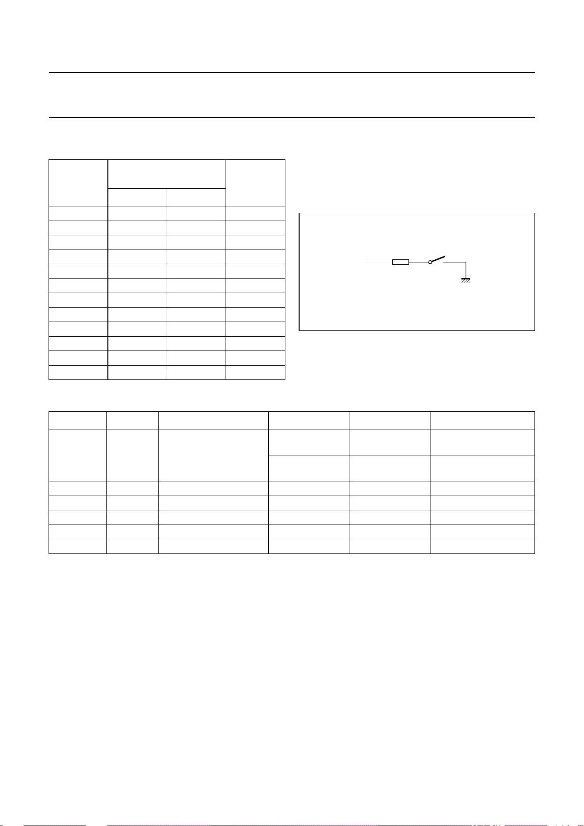
Table 6 Digits keypad activation and corresponding
DTMF frequency pairs
DIGIT
FREQUENCIES
KEYS
fL(Hz) fH(Hz)
[0] 941 1336 10
[1] 697 1209 1
[2] 697 1336 2
[3] 697 1477 3
[4] 770 1209 4
[5] 770 1336 5
[6] 770 1477 6
[7] 852 1209 7
[8] 852 1336 8
[9] 852 1477 9
[#] 941 1477 −
[∗/T] 941 1209 −
GENERATED DTMF
NUMBER
OF
PULSES
UBA2050(A); UBA2051(A;C)
Resistor options
The resistors are connected between the pins of the
keyboard (C1 to C3 and R1 to R4) and pin GND. One
resistor connection is shown in Fig.26. The resistor
options are read after each reset of the dialler.
handbook, halfpage
R1
Fig.26 Resistor connection.
MBS
MGT048
Table 7 Resistor functions
RESISTOR TO PIN FUNCTION CONDITIONS ON
FTSA C2 flash time select FTSB = off;
300 ms 98 ms
(1)
OFF
(1)
note 2
FTSB = on;
80 ms 600 ms
note 2
MMS C1 [∗/T] key definition [∗/T] becomes [∗] [∗/T] becomes [P → T]
MBS R1 make/break ratio select 33/66 40/60
APT R2 access pause time select 3.6 s 2.0 s
PPS R3 pulses per second 20 pps 10 pps
PTS R4 pulse/tone select pulse mode DTMF mode
Notes
1. On = option resistor present; off = option resistor not present.
2. Pin C3 belongs to resistor option FTSB.
2000 May 19 25
Page 26
Philips Semiconductors Product specification
One-chip telephone ICs with speech,
UBA2050(A); UBA2051(A;C)
dialler and ringer functions
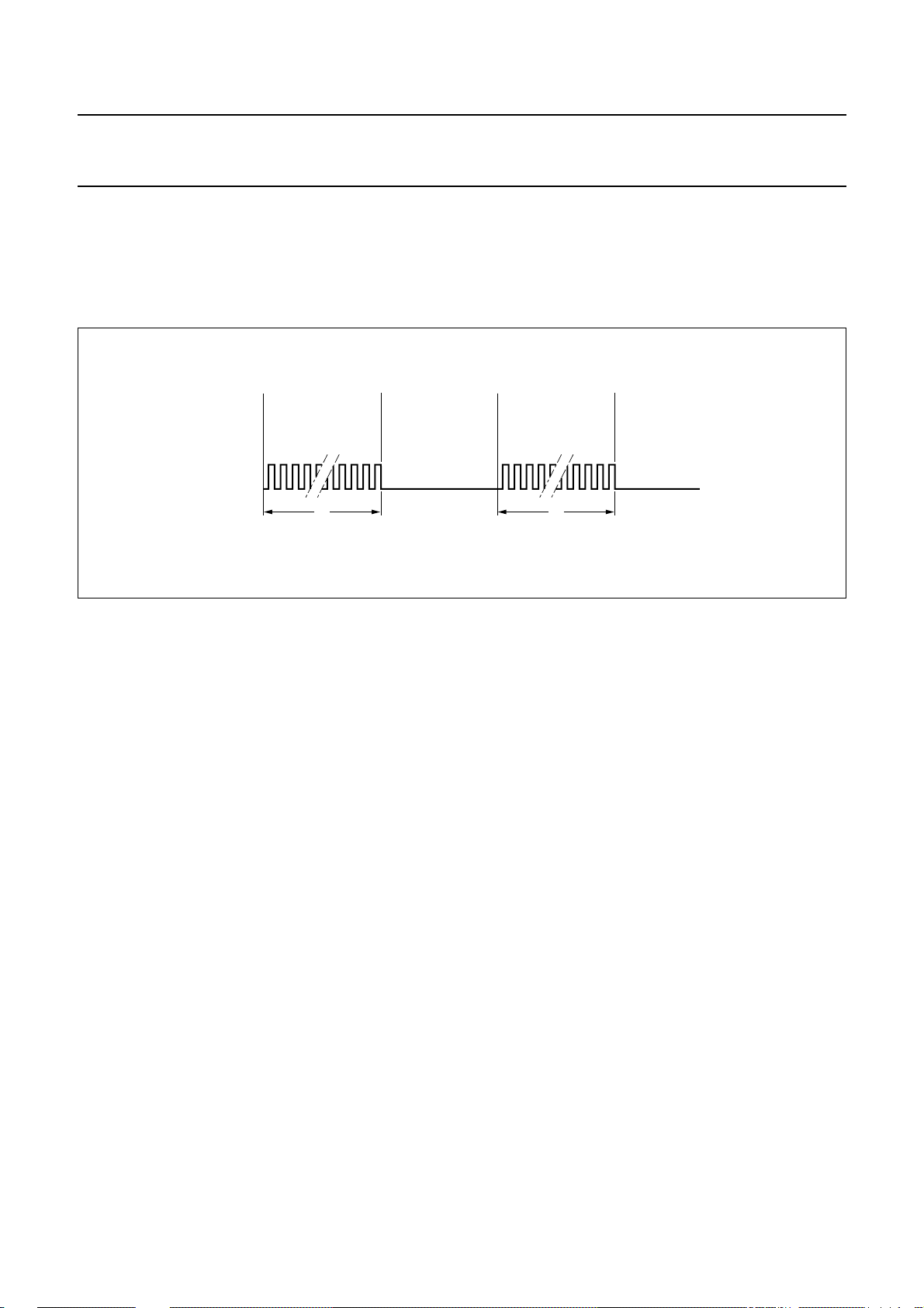
KEY TONE (PIN KT)
A keytone with a frequency fkt= 597 Hz and a duration tkt= 30 ms (see Fig.27) is generated each time a valid key is
pressed resulting in the expected action, digit keys in tone dialling mode excepted.
Pin KT is a push-pull output and is set LOW when VDD<V
handbook, full pagewidth
f
kt
keytone
t
tkt= keytone time.
fkt= keytone frequency.
kt
Fig.27 Keytones via KT output.
POR
.
f
kt
t
kt
MGM344
Key sequences
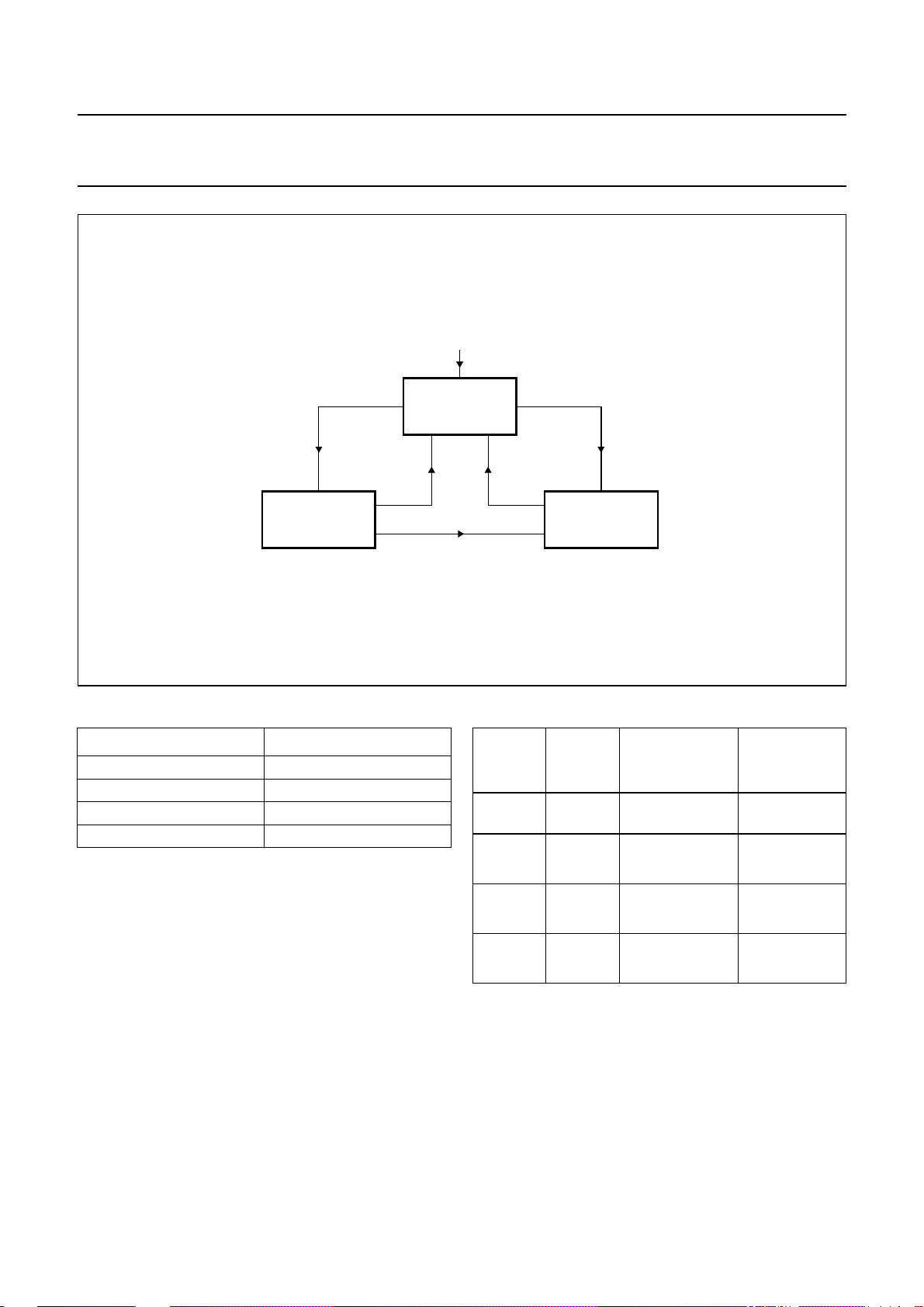
The behaviour of the UBA205xx can be represented as
a State Transition Diagram (STD).
The STD contains the states (rectangles in Fig.28) and
statetransitions (arrows) ofthe set. The upperarrow in the
figure pointing to the standby state means that the set is
initially in the standby state. When, for instance, an
incoming call is detected, the set enters the ringer state,
waiting for end ofa ringer signalor off-hook. If theset goes
off-hook, the UBA205xx enters the on-line state.
The UBA205xx has 3 basic states:
• Standby state
• Ringer state
• On-line state.
Each state with its own functional requirements is
described in the following sections.
STANDBY STATE
In the standby state theUBA205xx is inactive. The current
drawn is for memory retention; the loads on the
inputs/outputsof the dialler have influenceonthe retention
current.
The UBA205xx leaves the standby state if:
• The set goes off-hook (lift handset)
• A ringer signal is available on the line.
The UBA205xx returns to the standby state if:
• The set goes on-hook (handset on-hook)
• A line-break occurs with a duration greater than t
RD
• The ringer signal becomes invalid.
RINGER STATE
Iftheset is in standby state, a ringersignalcanbe received
from the line. After evaluating the incoming ringer signal
(and the ringer signal is valid), the UBA205xx starts a
melody via the MDY/TONE output and ringer hardware;
this melody is stopped when the ringer signal is no longer
valid. After going off-hook, the ringer signal stops and the
set is in the conversation (on-line) state.
While ringing, the melody can be changed according to
Table 8 and the volume according to Table 9.
As long as memory retention conditions are fulfilled,
melody and volume are stored.
2000 May 19 26
Page 27
Philips Semiconductors Product specification
One-chip telephone ICs with speech,
dialler and ringer functions
handbook, full pagewidth
ringer signal
ringer invalid
power-on
STANDBY
off-hook
UBA2050(A); UBA2051(A;C)
off-hook
on-hook/line break
ON-LINERINGER
MGU186
Fig.28 UBA205xx standby, ringer and on-line states.
Table 8 Melody selection during ringer state Table 9 Ringer volume setting during ringing
MELODY KEY
Bell 1 [1] (default)
Bell 2 [2]
Bell 3 [3]
Bell 4 [4]
KEY VOLUME ATTENUATION
[8]
highest 0 dB V
(default)
[7] high −6dB
[6] low −12 dB
[5] lowest −18 dB
AMPLITUDE
MDY/TONE
DD
V
DD
------------------------ -
V
DD
------------------------ -
V
DD
------------------------ -
2
4
8
OF
0.7–
0.7–
0.7–
0.7+
0.7+
0.7+
2000 May 19 27
Page 28
Philips Semiconductors Product specification
One-chip telephone ICs with speech,
dialler and ringer functions
ON-LINE STATE
This section describes all the actions of the UBA205xx
during the on-line state. This state starts with making
output DP/FL HIGH (external pull-up resistor), which
makes line current flow possible.
handbook, full pagewidth
RINGER
off-hook
ON-LINE
[LNR/P], [M1 to M3], [MEM] + [0] to [9]
end of recall
UBA2050(A); UBA2051(A;C)
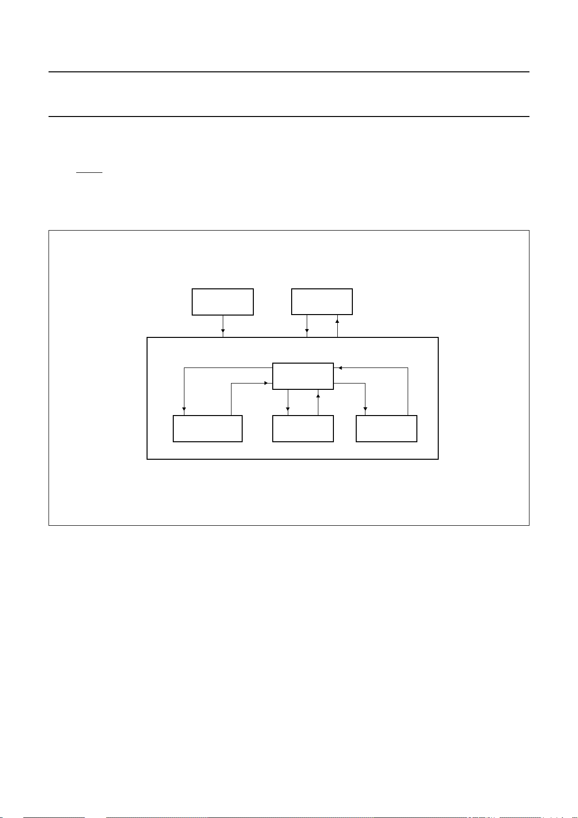
The on-line state contains a number of sub-states
(see Fig.29):
• Conversation state
• Dialling state
• Memory recall state
• Program state.
STANDBY
on-hook/line breakoff-hook
[M1 to M3], [MEM] + [0] to [9]
CONVERSATION
[STORE]
dial keys
Fig.29 On-line states.
Conversation state
In this state, conversation is possible.
Dialling state
During the dial-key entries the UBA205xx starts
immediately with transmission of the digit(s); the minimum
transmission time is unaffected by the speed of the entry.
Transmission continues as long as further dial-key entries
have to be processed.
end
PROGRAMDIALLINGMEMORY RECALL
MGU187
However when more than 32 digits are dialled the
LNR memory will overflow and the last number redial
function will be inhibited.
There are two dial modes: pulse dialling and tone dialling.
The initial dialling mode is determined by resistor option
PTS.
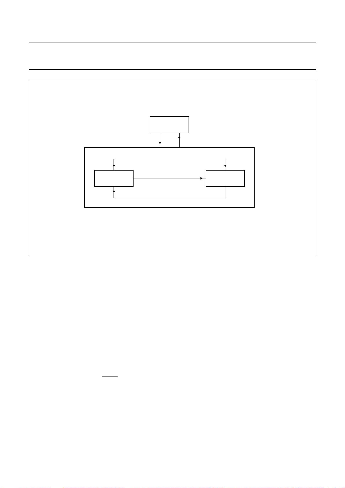
The state machine which controls the dialling mode is
illustrated in Fig.30.
2000 May 19 28
Page 29
Philips Semiconductors Product specification
One-chip telephone ICs with speech,
dialler and ringer functions
handbook, full pagewidth
CONVERSATION
PTS = on PTS = off
DIALLING
[
/T] or [P->T]
*
[R] + PTS = on
UBA2050(A); UBA2051(A;C)
enddial keys
TONE DIALLINGPULSE DIALLING
MGM347
Fig.30 Dialling mode state machine.
• Pulse dialling
Inthismode all valid keys aredialledbythe pulse dialler.
When,during pulse dialling, either[∗/T]when MMS is off
or [P → T] is pressed, the UBA205xx switches over to
tonedialling(mixedmodedialling).After the switch over,
valid keys are dialled by the tone dialler. The temporary
tone mode is terminated by going on-hook or flash
(Recall).
• Tone dialling
The UBA205xx converts valid key entries into data for
the on-chip DTMF generator. Tones are transmitted via
output MDY/TONE with a minimum tone burst/pause
duration. The maximum tone burst duration is equal to
the key pressing time.
• Flash function
The [R] key will result in pin DP/FL being set to LOW to
generate a flash (line current interruption) with a
selected time (FTSA and FTSB resistor options).
Pressing one digit after [R] key is pressed clears the
LNR memory. When going on-hook after the [R] key is
pressed, then digits previously dialled in the LNR
memory are kept.
• Access pause
When the [LNR/P] button is not the first key pressed, an
access pause is entered for repertory or redialling
procedures.
• Last number redial
If the first key pressed is [LNR/P], the number stored in
the LNR memory is dialled and sent. A maximum
number of 32 digits can be stored in the LNR memory.
If this maximum is exceeded the redial function is
inhibited. Pauses, which are stored in the LNR memory,
are also dialled.
The tone switch keys [∗/T] (when MMS is off) and
[P → T] are also stored in the LNR memory. When a
[∗/T] key (when MMS is on) or [#] key occurs during
pulse dialling, its code is not stored in the LNR memory.
The LNR memory is always cleared when the [STORE]
key is pressed. Its content may also be programmed
(see Section “Program state (only UBA2051x)”).
2000 May 19 29
Page 30

Philips Semiconductors Product specification
One-chip telephone ICs with speech,
dialler and ringer functions
Memory recall state (only UBA2051x)
Repertory numbers can be dialled out after or before
entering manual dialling, last number redial and by
entering the memory locations in successive order.
Repertory recall is not possible as long as a dial out is
pending.The three direct memory locationsare numbered
[M1] to [M3] and the ten indirect memory locations
[MEM] [1] to [MEM] [0].
The stored numbers can be dialled by using one of the
following procedures:
Press one of the direct memory keys [M1] to [M3]
or
Press [MEM], followed by one of the numeric keys
[1] to [0], corresponding to the memory locations 1 to 10.
In case [R] is included in one memory location, when the
LNR capacity is exceeded by using it, the LNR function is
inhibited.
Program state (only UBA2051x)
The program state can be entered from the conversation
mode (on-line) when no dial out is pending. Pressing the
[STORE] key in this state puts the UBA2051x in the
program state and also clears the LNR memory. Pressing
the [STORE] keyagain in the program state will restart the
program sequence.
• Leaving the program state
The program state can be left in one of the following
ways:
– By going on-hook;the entered digits are stored in the
LNR memory
– Byending the storeprocedures properly (see below),
resulting in a proper store of the programmed item.
• Programming repertory numbers
A maximum number of 32 digits can be stored in the
memoryofrepertorynumbers(includingaccesspauses,
tone switch and flash) and can be achieved by using the
following procedure:
UBA2050(A); UBA2051(A;C)
– Press [STORE]; the LNR memory is cleared
– Press the sequence of digits that must be stored; the
keys [0] to [9], [#], [LNR/P], [∗/T], [P → T] or [R] may
be used
– Store the number in the memory.
• Memory overflow
If more than 21 digits are entered the old memory
contents is kept and the LNR memory is cleared. All the
following digits are ignored, except the [STORE] key.
The memory overflow state can be left:
– By going on-hook
– By pressing the [STORE] key again to restart the
program sequence.
• Clear repertory numbers
Clearing a memory location is possible by using the
same procedure as for storing a number, except that no
telephone number is entered:
– Press [STORE]; the LNR memory will be cleared
– Press one of the memory keys.
• Notepad function
In the conversation state it is possible to store a 21 digit
number into the LNR memory, which may be dialled
after an on-hook/off-hook action. The procedure is as
follows:
– Press [STORE], the LNR memory will be cleared
– Press the sequence of digits that must be stored; the
keys [0] to [9], [#], [LNR/P], [∗/T], [P → T] or [R] may
be used
– Go on-hook/off-hook.
2000 May 19 30
Page 31
Philips Semiconductors Product specification
One-chip telephone ICs with speech,
UBA2050(A); UBA2051(A;C)
dialler and ringer functions
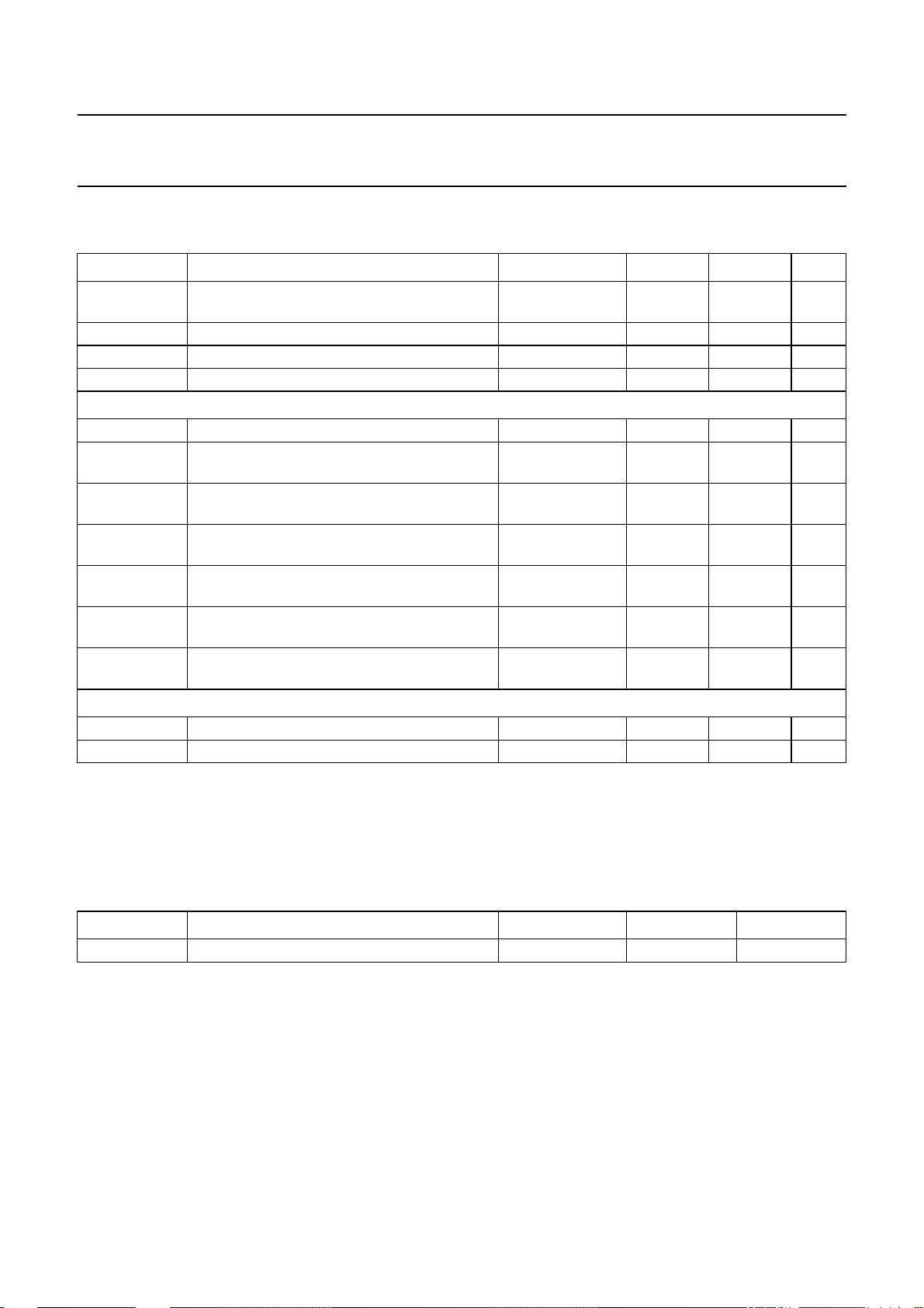
LIMITING VALUES
In accordance with the Absolute Maximum Rating System (IEC 60134).
SYMBOL PARAMETER CONDITIONS MIN. MAX. UNIT
P
tot
T
amb
T
stg
T
j
total power dissipation R
ambient temperature −25 +75 °C
storage temperature −40 +125 °C
junction temperature − 125 °C
Speech/transmission part
V
V
LN
LN(R)
positive continuous voltage on pin LN GND − 0.4 12 V
repetitive voltage on pin LN during switch-on
or line interruption
I
LN
V
CC
line current R
supply voltage for the speech/transmission
part and peripherals
V
DD
stabilized supply voltage for the dialler and
ringer parts
I
DD
input current at pin VDD for the dialler and
ringer parts
V
n
voltage on pins SLPE, IR, REG, AGC, DTMF,
RX, QR, GAR, MIC+ and MIC−
Dialler and ringer parts
V
n
I
n
voltage on pins 8 to 21 GND − 0.4 VDD+ 0.4 V
DC sink/source current for pins 8 to 21 −10 +10 mA
SLPE
=20Ω;
− 625 mW
note 1
GND − 0.4 13.2 V
SLPE
=20Ω;
− 140 mA
note 2
GND − 0.4 12 V
IDD≤ 75 mA GND − 0.4 3.6 V
I
=0mA − 75 mA
line
GND − 0.4 VCC+ 0.4 V
Notes
1. Calculated for T
=75°C and Tj= 125 °C.
amb
2. Mostly dependent on the maximum required ambient temperature and on the voltage between pins LN and SLPE
(see Fig.31).
THERMAL CHARACTERISTICS
SYMBOL PARAMETER CONDITIONS VALUE UNIT
R
th(j-a)
thermal resistance from junction to ambient in free air; note 1 70 K/W
Note
1. Mounted on glass epoxy board 28.5 × 19.1 × 1.5 mm.
2000 May 19 31
Page 32
Philips Semiconductors Product specification
One-chip telephone ICs with speech,
dialler and ringer functions
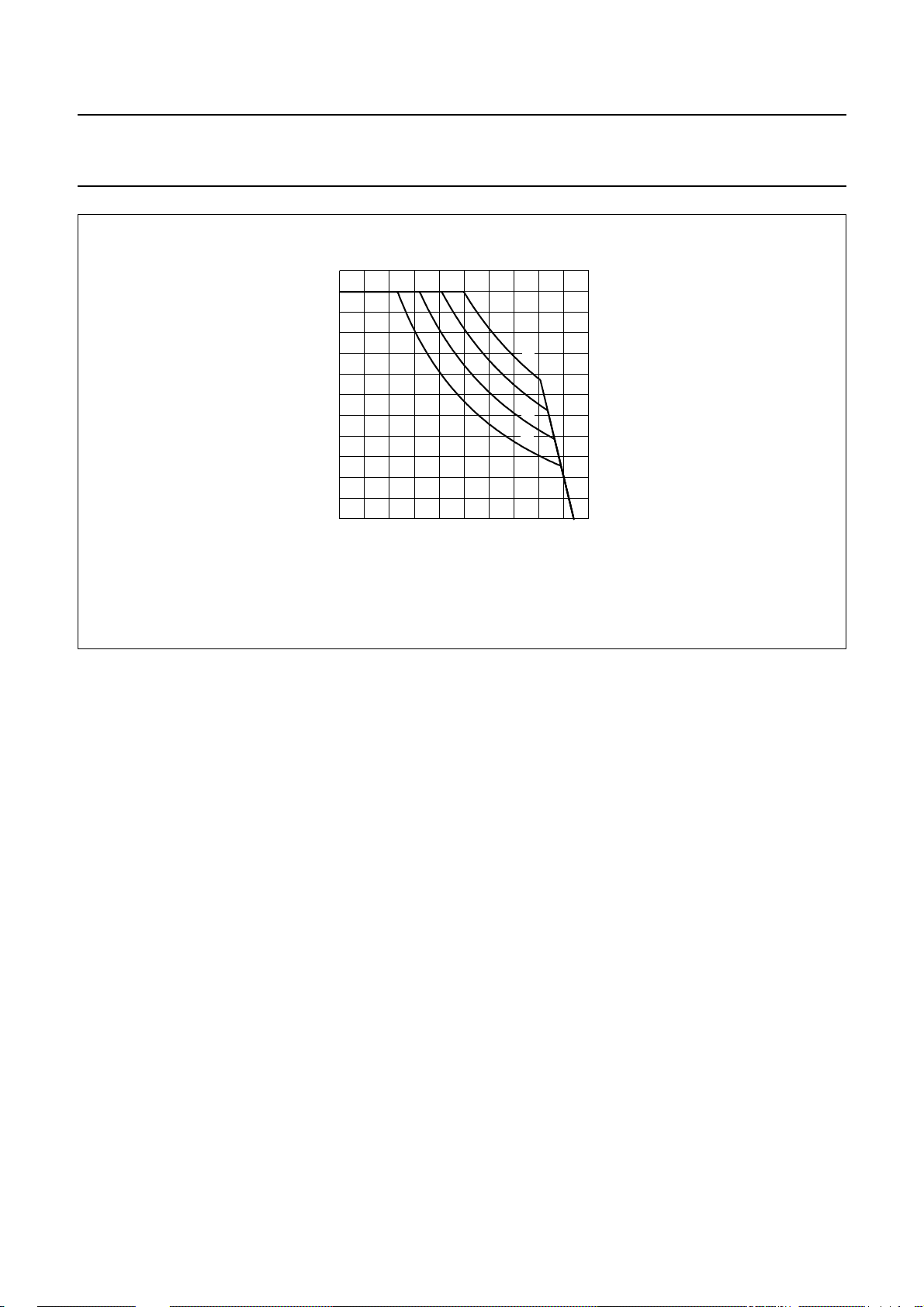
150
handbook, halfpage
I
LN
(mA)
110
70
30
(1) T
(2) T
(3) T
(4) T
amb
amb
amb
amb
=45°C; P
=55°C; P
=65°C; P
=75°C; P
= 1.000 W.
tot
= 0.875 W.
tot
= 0.750 W.
tot
= 0.625 W.
tot
212
46810
VLN−V
UBA2050(A); UBA2051(A;C)
FCA134
(1)
(2)
(3)
(4)
(V)
SLPE
Fig.31 Safe operating area.
2000 May 19 32
Page 33
Philips Semiconductors Product specification
One-chip telephone ICs with speech,
UBA2050(A); UBA2051(A;C)
dialler and ringer functions
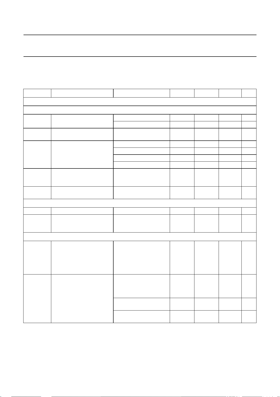
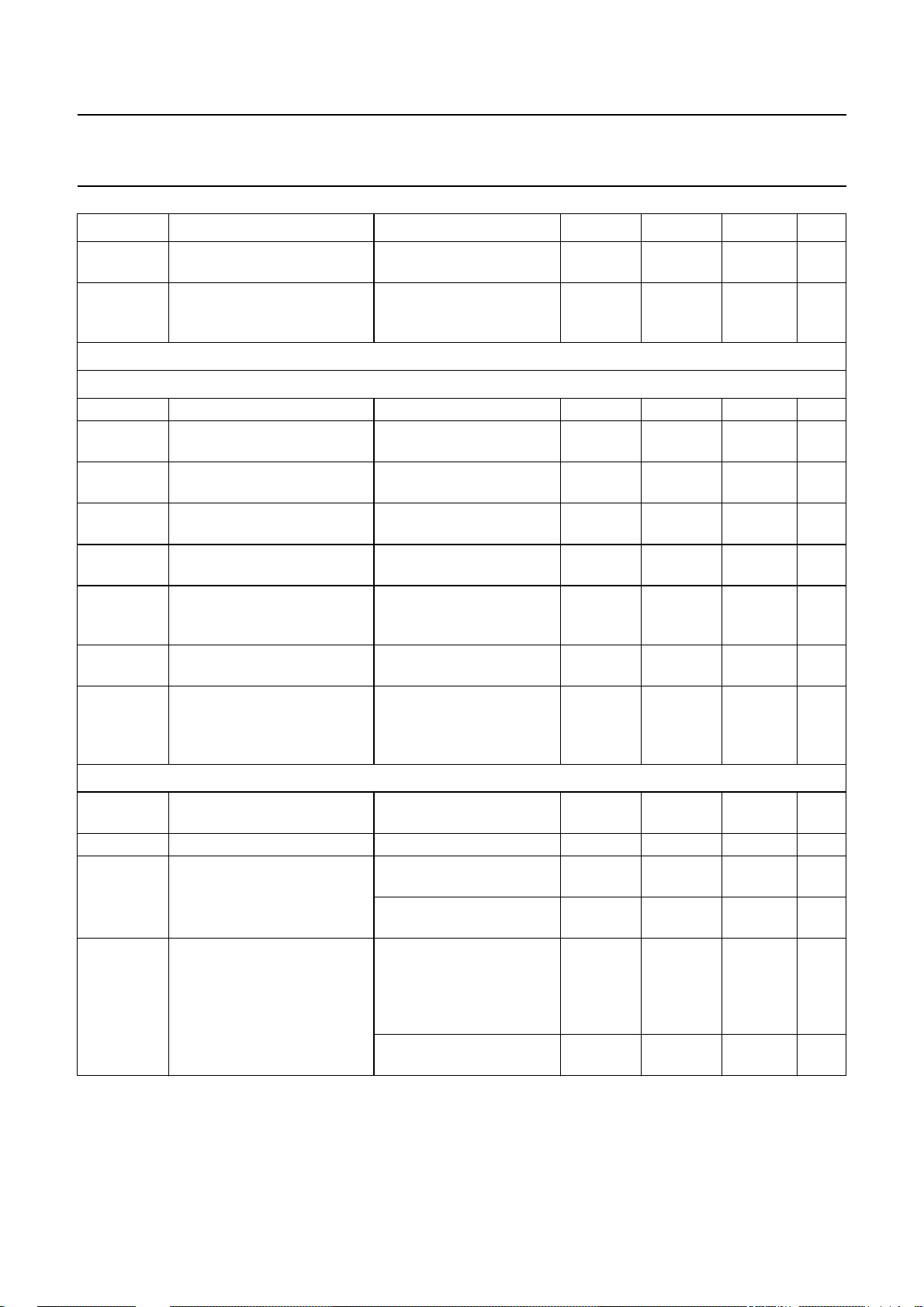
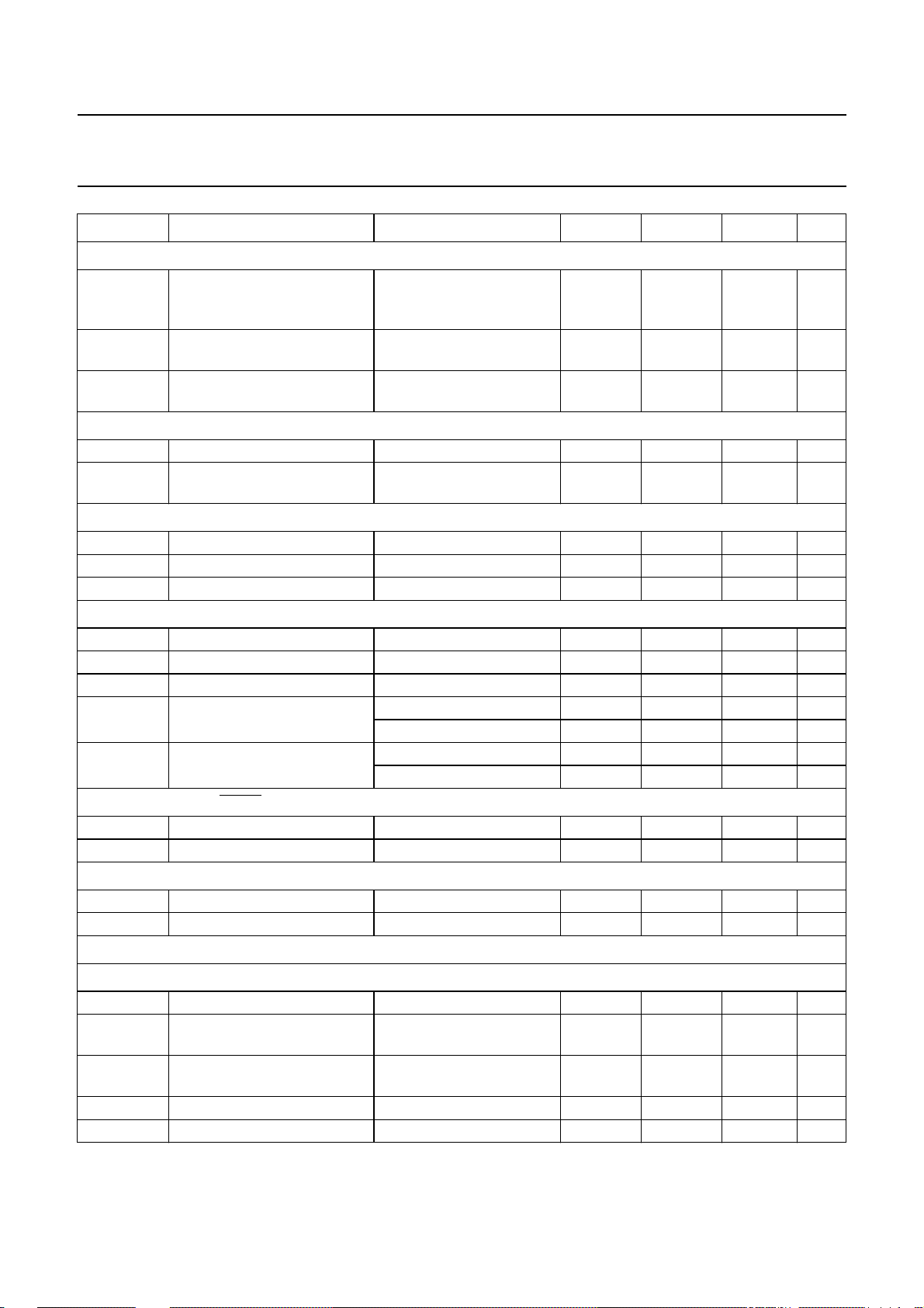
CHARACTERISTICS
I
= 15 mA; GND = 0 V; R
line
T
=25°C; measured according to the test circuits of Figs 32, 33 and 34; see also Figs 37 and 38; unless otherwise
amb
specified.
SYMBOL PARAMETER CONDITIONS MIN. TYP. MAX. UNIT
Supplies
INE INTERFACE (PIN LN)
L
I
V
line
ref
line current operating range normal operation 11 − 140 mA
stabilized reference voltage
between pins LN and SLPE
V
LN
V
LN(Rext)
DC line voltage I
DC line voltage with external
resistor
∆V
LN(T)
DC line voltage variation with
temperature
INTERNAL SUPPLY VOLTAGE (PIN VCC)
I
CC
V
CC
internal current consumption VCC= 3.6 V − 1.25 1.5 mA
supply voltage for
speech/transmission part and
peripherals
REGULATED SUPPLY VOLTAGE (PIN VDD)
I
SUP
input current of the V
regulator
V
DD
regulated supply voltage speech mode;
=20Ω; pin AGC connected to GND; Z
SLPE
reduced performance 1 − 11 mA
=1mA − 1.45 − V
line
I
=4mA − 2.0 − V
line
I
= 15 mA 4.05 4.35 4.65 V
line
= 140 mA − 7.1 7.55 V
I
line
external resistor
RVA= 44.2 kΩ (between
pins LN and REG)
T
= −25 to +75 °C;
amb
referenced to T
IP=0mA − 3.6 − V
DD
current from pin LN not
flowing through pin SLPE
=1mA − 0 − mA
I
line
I
=4mA − 2.15 − mA
line
≥ 11 mA − 4.5 − mA
I
line
IDD= −2.6 mA;
VLN> 3.6 V + 0.25 V (typ.);
I
≥ 11 mA
line
speech mode at reduced
performance; I
ringer mode; I
IDD=75mA
amb
line
line
=25°C
=4mA
= 0 mA;
= 600 Ω; f = 1 kHz; f
line
= 3.579545 MHz;
xtal
3.9 4.15 4.4 V
− 3.6 − V
−±40 − mV
3.0 3.3 3.6 V
− VLN− 0.35 − V
3.0 3.3 3.6 V
2000 May 19 33
Page 34
Philips Semiconductors Product specification
One-chip telephone ICs with speech,
UBA2050(A); UBA2051(A;C)
dialler and ringer functions
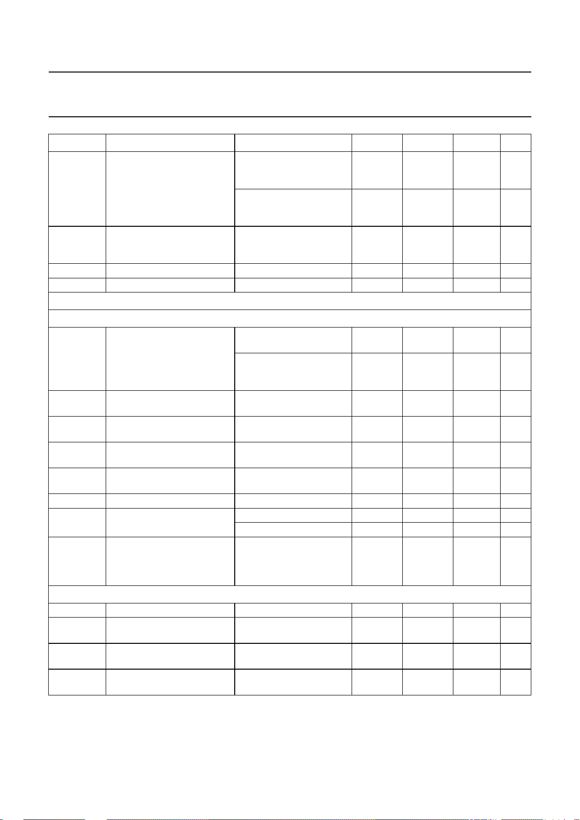
SYMBOL PARAMETER CONDITIONS MIN. TYP. MAX. UNIT
I
DD
I
DD(MR)
V
DD(MR)
V
DD(POR)
Transmit stages
MICROPHONE AMPLIFIER (PINS MIC+ AND MIC− AND LN)
input impedance differential between
Z
i
G
v(TX)
∆G
v(TX)
∆G
v(TX)(f)
∆G
v(TX)(T)
CMRR common mode rejection ratio − 80 − dB
V
LN(max)(rms)
V
n(LN)
DTMF AMPLIFIER (PIN DTMF)
Z
input impedance − 21 − kΩ
i
G
v(DTMF)
∆G
v(DTMF)
∆G
v(DTMF)(f)
available supply current for
peripherals in on-line mode
I
≥ 11 mA;
line
DTMF generator on;
−−−1.9 mA
no AC signal on the line
I
≥ 11 mA;
line
−−−2.6 mA
DTMF generator off;
no AC signal on the line
memory retention current
(internal consumption
on VDD)
I
= 0 mA;
line
VCCdischarging;
VDD= 1.2 V
−−300 nA
memory retention voltage 1.0 − 3.6 V
Power-on reset trip level note 1 1.3 1.65 2.0 V
− 68 − kΩ
pins MIC+ and MIC−
single-ended between
− 34 − kΩ
pin MIC+ or MIC−
and GND
voltage gain from pins
V
= 4 mV (RMS) 43.2 44.2 45.2 dB
MIC
MIC+ or MIC− to LN
voltage gain reduction of
internal MUTE active − 80 − dB
microphone amplifier
voltage gain variation with
frequency
voltage gain variation with
temperature
maximum sending signal
voltage level (RMS value)
noise output voltage at pin LN psophometricallyweighted
f = 300 to 3400 Hz;
−±0.2 − dB
referenced to f = 1 kHz
T
= −25 to +75 °C;
amb
referenced to T
I
= 15 mA; THD = 2% 1.8 2.15 − V
line
I
= 4 mA; THD = 10% − 0.35 − V
line
amb
=25°C
−±0.3 − dB
−−78 − dBmp
(P53 curve); pins MIC+
and MIC− shorted through
200 Ω
voltage gain from pin
DTMF to pin LN
voltage gain reduction of
in tone dialling mode;
V
= 20 mV (RMS)
DTMF
− 26 − dB
internal MUTE inactive − 80 − dB
DTMF amplifier
voltage gain variation with
frequency
f = 300 to 3400 Hz;
referenced to f = 1 kHz
−±0.2 − dB
2000 May 19 34
Page 35
Philips Semiconductors Product specification
One-chip telephone ICs with speech,
UBA2050(A); UBA2051(A;C)
dialler and ringer functions
SYMBOL PARAMETER CONDITIONS MIN. TYP. MAX. UNIT
∆G
v(DTMF)(T)
G
v(ct)
Receive stages
RECEIVE AMPLIFIER (PINS IR AND RX)
input impedance − 21.5 − kΩ
Z
i
G
v(RX)
∆G
v(RX)
∆G
v(RX)(f)
∆G
v(RX)(T)
I
o(RX)(max)
V
RX(max)(rms)
V
n(RX)(rms)
EARPIECE AMPLIFIER (PINS GAR AND QR)
G
v(QR)
∆G
v(QR)
V
QR(max)(rms)
V
n(QR)(rms)
voltage gain variation with
temperature
voltage gain from pin DTMF
to pin RX (confidence tone)
T
= −25 to +75 °C;
amb
referenced to T
amb
=25°C
in tone dialling mode;
V
= 20 mV (RMS);
DTMF
−±0.4 − dB
−−9.2 − dB
RL2=10kΩ;
voltage gain from
VIR= 4 mV (RMS) 32.4 33.4 34.4 dB
pin IR to pin RX
voltage gain reduction of
internal MUTE active − 80 − dB
receive amplifier
voltage gain variation with
frequency
voltage gain variation with
temperature
maximum source and sink
f = 300 to 3400 Hz;
−±0.2 − dB
referenced to f = 1 kHz
T
= −25 to +75 °C;
amb
referenced to T
amb
=25°C
−±0.3 − dB
IP= 0 mA; sine wave drive 50 −−µA
current on pin RX
(peak value)
maximum receiving signal on
pin RX (RMS value)
noiseoutputvoltageat pin RX
(RMS value)
IP= 0 mA; sine wavedrive;
without RL2; THD = 2%
pin IR open-circuit;
RL2=10kΩ;
0.4 −−V
−−86 − dBVp
psophometrically weighted
(P53 curve)
voltage gain from pin RX to
pin QR
VIR= 4 mV (RMS);
RE1=R
GAR
= 100 kΩ
− 0 − dB
voltage gain setting range RE1= 100 kΩ−14 − +12 dB
maximum receiving signal on
pin QR (RMS value)
IP= 0 mA; sine wavedrive;
RL1= 150 Ω; THD = 2%
= 0 mA; sine wavedrive;
I
P
0.3 0.38 − V
0.46 0.56 − V
RL1= 450 Ω; THD = 2%
noise output voltage at
pin QR (RMS value)
IR open-circuit;
RL1= 150 Ω;
RE1=R
GAR
= 100 kΩ;
−−86 − dBVp
psophometrically weighted
(P53 curve)
R
R
E1
GAR
= 100 kΩ;
=25kΩ
−−98 − dBVp
2000 May 19 35
Page 36
Philips Semiconductors Product specification
One-chip telephone ICs with speech,
UBA2050(A); UBA2051(A;C)
dialler and ringer functions
SYMBOL PARAMETER CONDITIONS MIN. TYP. MAX. UNIT
Automatic gain control (pin AGC)
∆G
v(trx)
voltage gain control range for
microphone and receive
amplifiers
I
start
highest line current for
maximum gain
I
stop
lowest line current for
minimum gain
Oscillator (pin XTAL)
V
R
XTAL
e(Zi)
DC voltage level − 0.5V
real part of input impedance
of pin XTAL
Control inputs (pins CE/CSI and CE/FDI)
V
IL
V
IH
I
LI
LOW-level input voltage GND − 0.4 − 0.2V
HIGH-level input voltage 0.8V
input leakage current GND < Vi<V
Keyboard inputs/outputs (pins C1 to C4, R1 to R4); note 2
V
V
I
OL
I
OH1
IL
IH
LOW-level input voltage 0 − 0.2V
HIGH-level input voltage 0.8V
port sink current LOW VOL= 0.15 V 0.7 1.6 − mA
port pull-up source 1 current
HIGH
I
OH2
port pull-up source 2 current
HIGH
Control output (pin DP/FL)
I
LI
I
OL
input leakage current GND < Vi<V
port sink current LOW Vo= 0.15 V 1 2.5 − mA
Control outputs (pins DMO, KT and LED)
I
OL
I
OH
port sink current LOW Vo= 0.4 V 1.5 4 − mA
port source current HIGH Vo=VDD− 0.15 V −1 −2 − mA
DTMF/ringer output
I
= 85 mA; referenced to
line
I
=15mA
line
V
= 100 mV (RMS);
XTAL
f
= 3.57 MHz
xtal
DD
VOH=V
V
VOH=V
V
IH(min)
OL=VIL(max)
IH(min)
OL=VIL(max)
DD
− 6.0 − dB
− 23 − mA
− 59 − mA
DD
− V
−−6−kΩ
V
DD
DD
− VDD+ 0.4 V
−500 − +500 nA
V
DD
DD
− V
DD
V
15 35 −µA
− 70 140 µA
30 80 − nA
− 150 300 nA
−500 − +500 nA
TONE GENERATOR (PIN MDY/TONE); note 3
I
maximum output current 70 100 −µA
o
V
HG(rms)
high group frequency voltage
DTMF mode − 181 − mV
(RMS value)
V
LG(rms)
low group frequency voltage
DTMF mode − 142 − mV
(RMS value)
G
V
V
DC
pre-emphasis of group 1.5 2.0 2.5 dB
DC voltage level − 0.5V
DD
− V
2000 May 19 36
Page 37
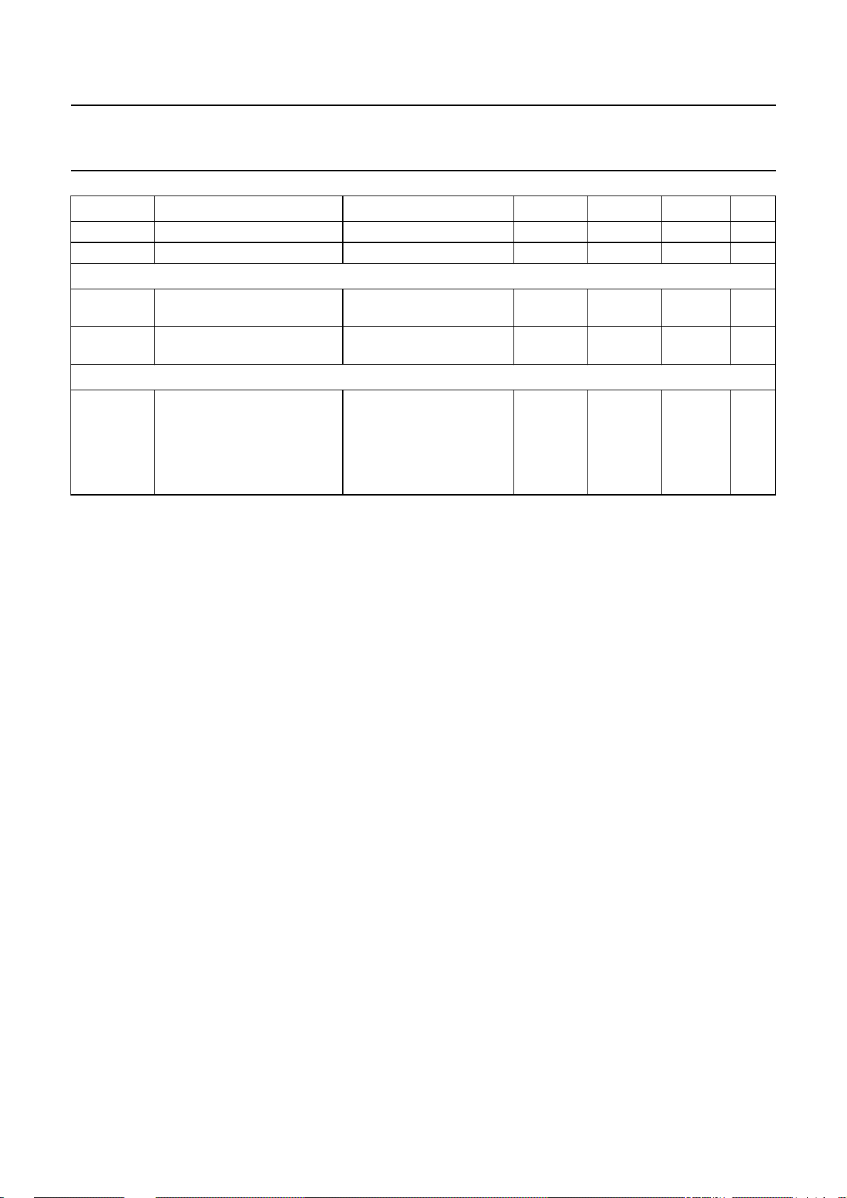
Philips Semiconductors Product specification
One-chip telephone ICs with speech,
UBA2050(A); UBA2051(A;C)
dialler and ringer functions
SYMBOL PARAMETER CONDITIONS MIN. TYP. MAX. UNIT
Zo output impedance − 100 500 Ω
THD total harmonic distortion note 4 −−25 − dB
T
RANSMIT CHANNEL (PIN LN)
V
HG(LN)(rms)
high group frequency voltage
(RMS value)
V
LG(LN)(rms)
low group frequency voltage
(RMS value)
MDY output (pin MDY/TONE)
V
o(p-p)
ringer volume output voltage
(peak-to-peak value)
Notes
1. When this level is reached at rising VDD, the internal reset signal is deactivated. There is no hysteresis in the
switching level, only hysteresis in the time domain.
2. At start-up the output has a pull-up source I
source will be I
OH1
.
3. MDY/TONE has three modes:
a) In speech mode or DTMF mode: 0.5VDD output.
b) In ringer mode: push-pull output stage.
c) In standby mode: high-impedance output.
4. Related to the low group frequency component (CEPT CS203 compatible).
5. In the event of a valid ringer signal present at pin CE/FDI.
R
R
R
R
DTMF1
DTMF2
DTMF1
DTMF2
=20kΩ;
= 2.74 kΩ
=20kΩ;
= 2.74 kΩ
353 435 536 mV
277 341 420 mV
VDD= 3.3 V; note 5
Key [8] − 3.2 − V
Key [7] − 2.0 − V
Key [6] − 1.4 − V
Key [5] − 1.1 − V
for detection of the resistor options. After initializing theoutput pull-up
OH2
2000 May 19 37
Page 38
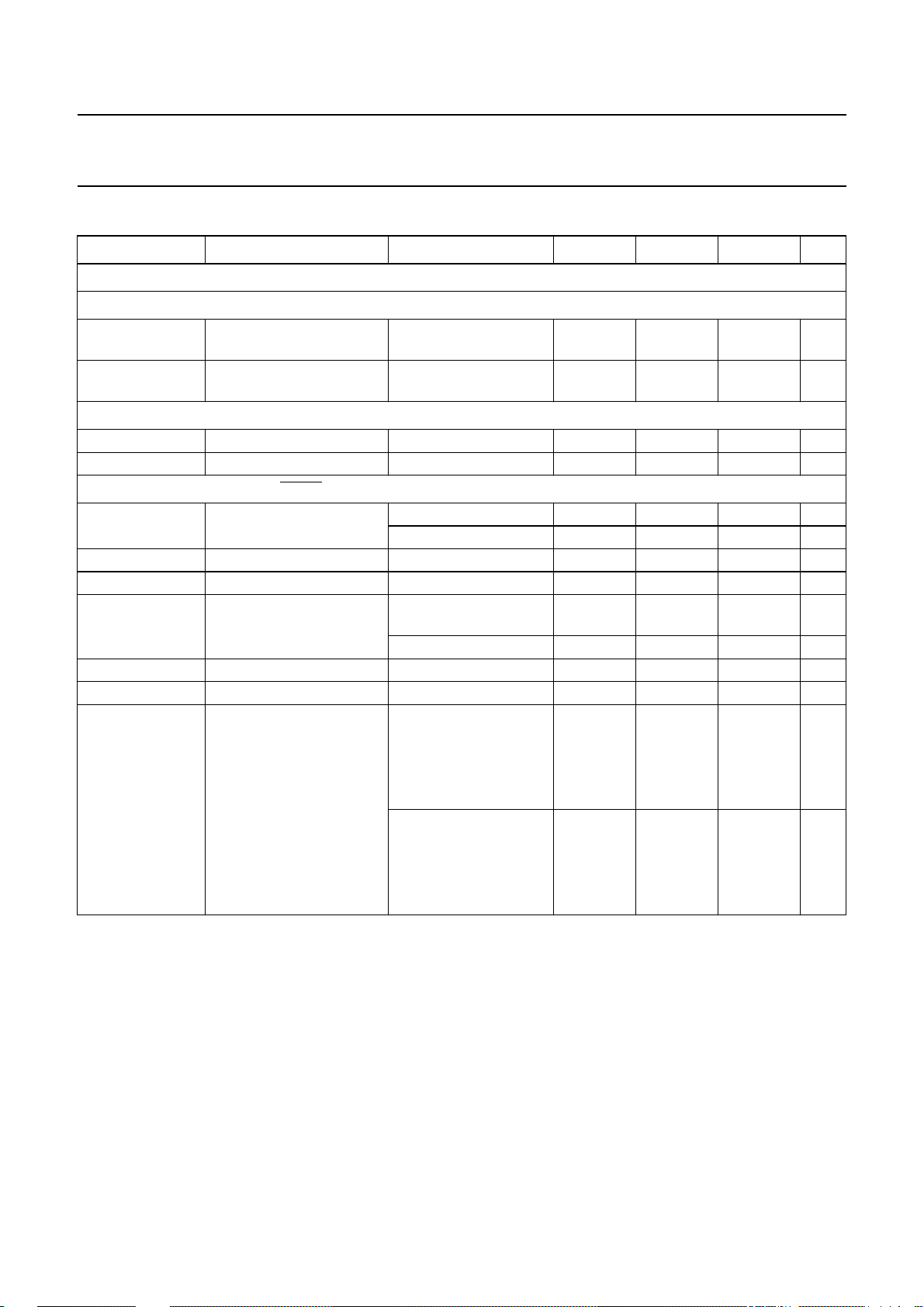
Philips Semiconductors Product specification
One-chip telephone ICs with speech,
UBA2050(A); UBA2051(A;C)
dialler and ringer functions
TIMING CHARACTERISTICS
SYMBOL PARAMETER CONDITIONS MIN. TYP. MAX. UNIT
Timing
KEYBOARD INPUTS/OUTPUTS (PINS C1 TO C4 AND R1 TO R4)
t
dd
keyboard depress
debounce time
t
rd
keyboard release
debounce time
KEY TONE OUTPUT (PIN KT)
t
kt
f
kt
keytone time − 30 − ms
keytone frequency − 597 − Hz
DIAL PULSE/FLASH OUTPUT (PIN DP/FL)
t
idp
t
fho
t
mho
t
ap
t
ifp
t
pdp
t
m
interdigit pause time dialling rate 10 pps − 800 − ms
flash holdover time − 40 − ms
mute holdover time − 15 − ms
access pause time resistor APT is not
interflash pause time − 800 − ms
pre-digit pause − 40 − ms
make time dialling rate 10 pps
dialling rate 20 pps − 500 − ms
present
resistor APT is present − 3.6 − s
resistor MBS is not
present
resistor MBS is
present
dialling rate 20 pps
resistor MBS is not
present
resistor MBS is
present
− 20 − ms
− 20 − ms
− 2.0 − s
− 40 − ms
− 33 − ms
− 20 − ms
− 16 − ms
2000 May 19 38
Page 39
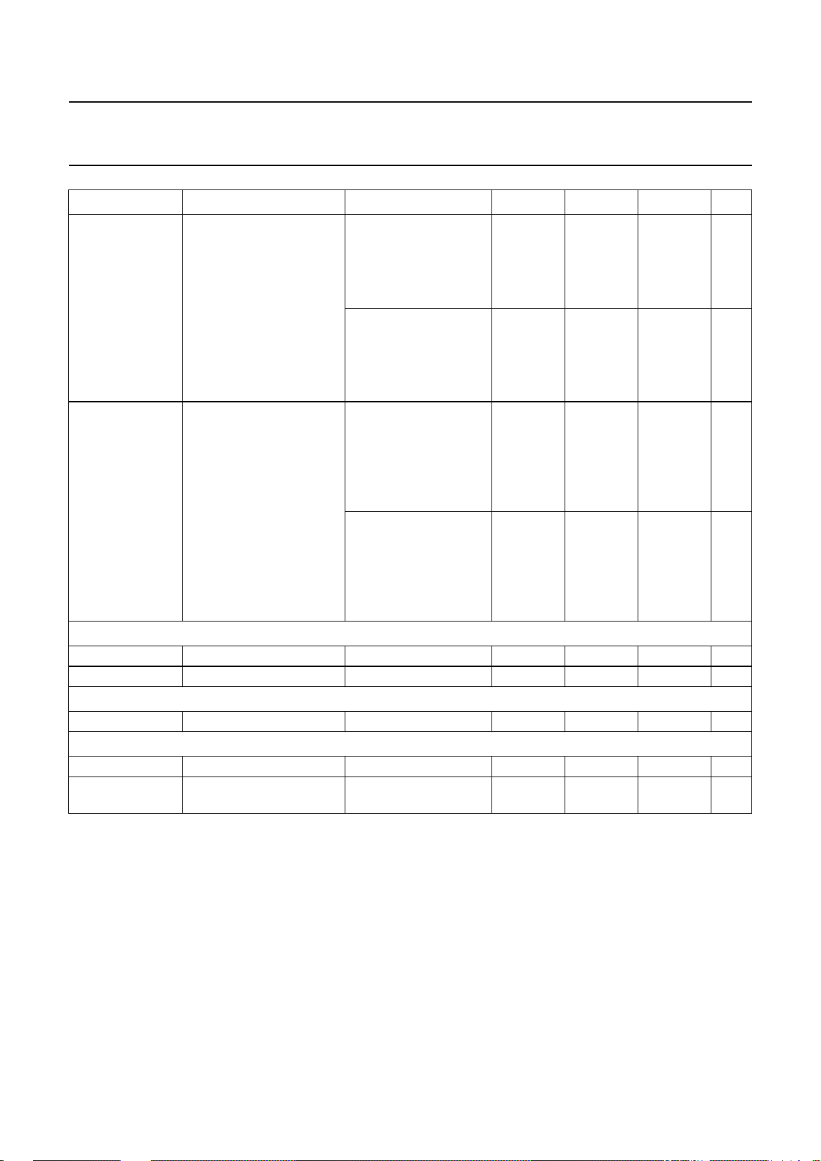
Philips Semiconductors Product specification
One-chip telephone ICs with speech,
UBA2050(A); UBA2051(A;C)
dialler and ringer functions
SYMBOL PARAMETER CONDITIONS MIN. TYP. MAX. UNIT
t
b
t
fl
D
IAL TONE OUTPUT (PIN MDY/TONE)
t
t
t
p
CHIP ENABLE INPUTS (PINS CE/CSI AND CE/FDI)
t
RD
Timing
f
ring
t
d(res)(ring)
brake time dialling rate 10 pps
resistor MBS is not
− 60 − ms
present
resistor MBS is
− 66 − ms
present
dialling rate 20 pps
resistor MBS is not
− 30 − ms
present
resistor MBS is
− 33 − ms
present
flash time resistor FTSB is not
present
resistor FTSA is not
− 98 − ms
present
resistor FTSA is
− 300 − ms
present
resistor FTSB is
present
resistor FTSA is not
− 600 − ms
present
resistor FTSA is
− 80 − ms
present
burst time − 85 − ms
pause time − 85 − ms
reset delay time − 280 − ms
ringer detection frequency 13 −−Hz
ringer response delay <1.5 frequency cycle;
VDD>V
POR
−−150 ms
2000 May 19 39
Page 40
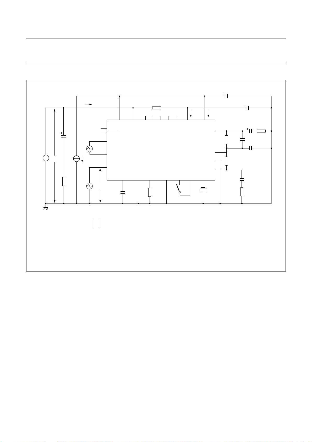
Philips Semiconductors Product specification
One-chip telephone ICs with speech,
dialler and ringer functions
TEST AND APPLICATION INFORMATION
handbook, full pagewidth
V
LN
LNCE/CSI C2 C3
REG AGC SLPE
C
REG
4.7 µF
I
line
I
line
IR
100
µF
V
O
Z
line
600
Ω
V
MIC
V
DP/FL
MIC−
MIC+
MDY/TONE
DTMF
DTMF
R
CC
619 Ω
R2 R3 R4
UBA205xx
GND
R
SLPE
20 Ω
UBA2050(A); UBA2051(A;C)
C
VDD
C1
V
CC
R1
S1
3.58 MHz
I
CC
CE/FDI
XTAL
X1
V
DD
GAR
QR
RX
I
220 µF
DD
R
GAR
R
E1
100 kΩ
C
VCC
100 µF
C
ear
C
GAR
C
GARS
100 nF
R
L2
10 kΩ
R
L1
FCA135
V
Voltage gain defined as Gv= 20 log ; VI=V
Microphone gain: S1 = open.
DTMF gain and confidence tone: S1 = closed.
Inputs not being tested should be open-circuit.
Only pins common to UBA205xx are represented. Pin 4 must be open-circuit.
O
------V
I
MIC
or V
DTMF
.
Fig.32 Test circuit for defining transmit gains.
2000 May 19 40
Page 41
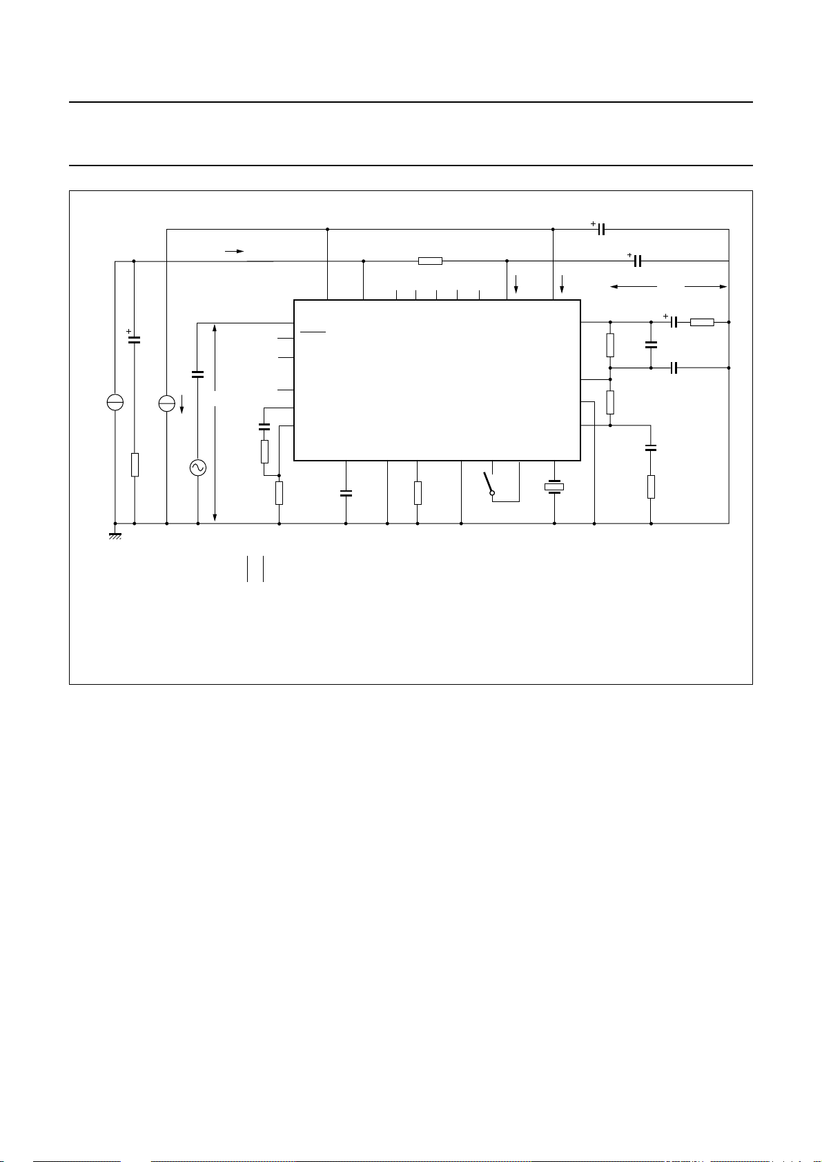
Philips Semiconductors Product specification
One-chip telephone ICs with speech,
dialler and ringer functions
handbook, full pagewidth
V
LN
LNCE/CSI C2 C3
REG AGC SLPE
C
REG
4.7 µF
I
line
100
µF
Z
600
Ω
line
220
nF
V
I
C
DTMF
100 nF
R
DTMF1
20 kΩ
I
line
IR
DP/FL
MIC−
MIC+
MDY/TONE
DTMF
R
DTMF2
2.74 kΩ
R
CC
619 Ω
R2 R3 R4
UBA205xx
GND
R
SLPE
20 Ω
UBA2050(A); UBA2051(A;C)
C
VDD
220 µF
C
VCC
100 µF
R
GAR
R
E1
100 kΩ
V
QR
C
ear
C
GAR
C
GARS
100 nF
R
L2
10 kΩ
R
L1
FCA136
V
C1
CC
R1
S1
3.58 MHz
I
CC
V
DD
CE/FDI
XTAL
X1
QR
GAR
RX
I
DD
V
Voltage gain defined as Gv= 20 log ; VO=VQRor VRX.
Receive and earpiece gains: S1 = open.
Inputs not being tested should be open-circuit.
Only pins common to UBA205xx are represented. Pin R4 must be open-circuit.
O
------V
I
Fig.33 Test circuit for defining receive gains and DTMF dialling levels.
2000 May 19 41
Page 42
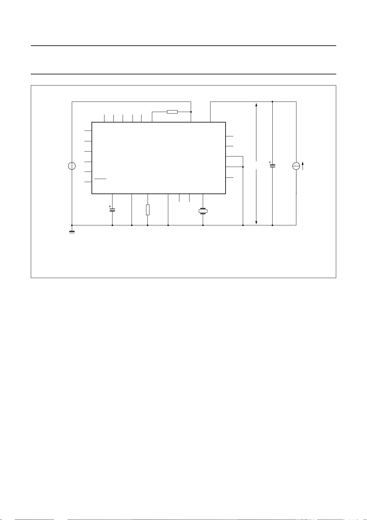
Philips Semiconductors Product specification
One-chip telephone ICs with speech,
dialler and ringer functions
handbook, full pagewidth
IR
MIC−
MIC+
V
CC
DTMF
MDY/TONE
DP/FL
REG AGC SLPE
C
REG
4.7 µF
LNR4R3R2C3C2
UBA205xx
GND C1 R1
R
SLPE
20 Ω
R
CC
619 Ω
UBA2050(A); UBA2051(A;C)
CC
XTAL
V
DD
QR
GAR
CE/CSI
CE/FDI
RX
X1
3.58 MHz
V
DD
10 µF
FCA137
I
DD
V
Inputs not being tested should be open-circuit.
Only pins common to UBA205xx are represented. Pin R4 must be open-circuit.
Fig.34 Test circuit for defining regulated supply (VDD) performance in ringer and trickle mode.
2000 May 19 42
Page 43
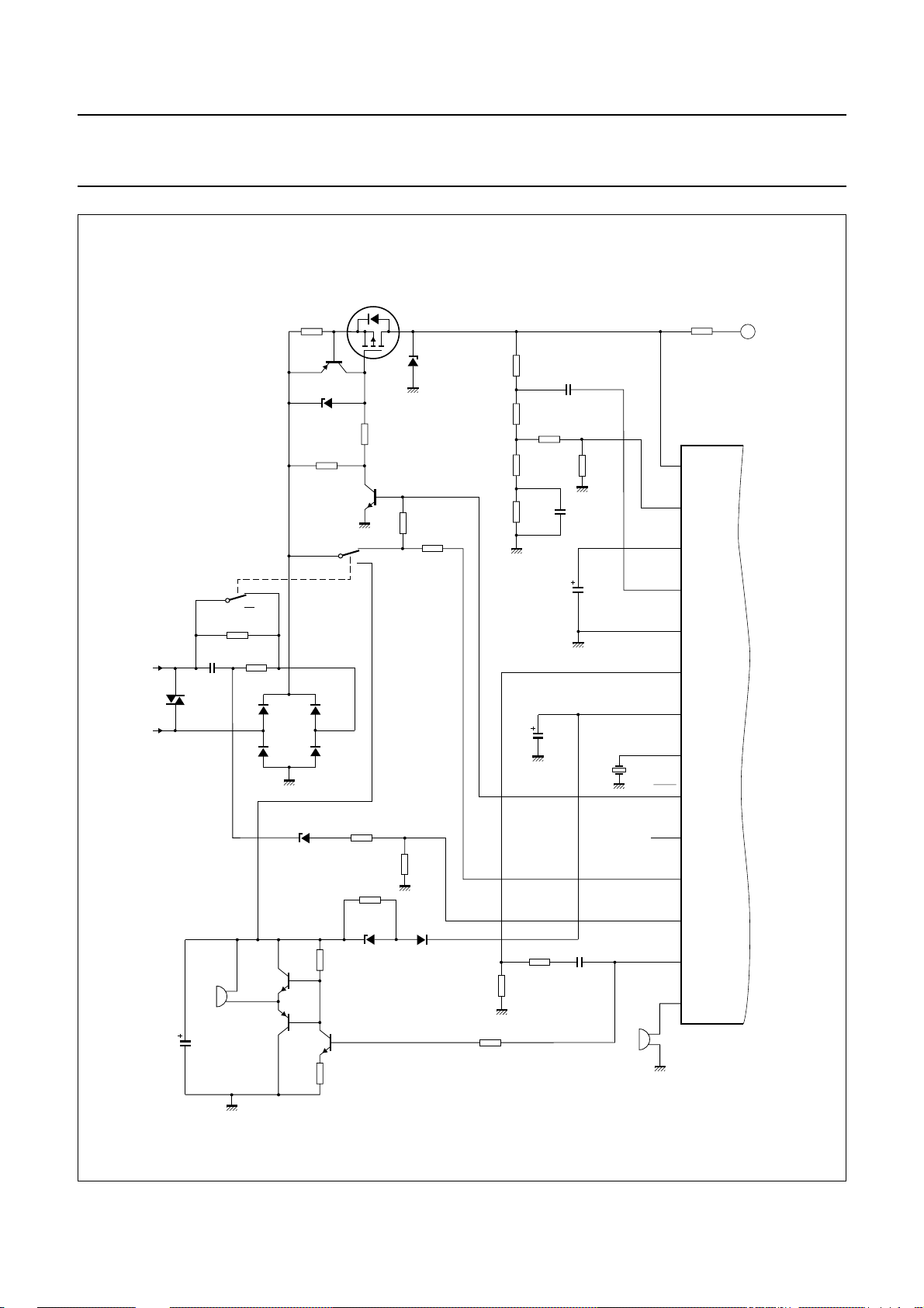
Philips Semiconductors Product specification
One-chip telephone ICs with speech,
dialler and ringer functions
470 kΩ
R3
TR1
BSP254A
Z1
470 kΩ
handbook, full pagewidth
S1-1
C
R
prot
3.9 Ω
TR2
BZX79C
470 kΩ
BC558
Z2
(8.2 V)
R1
BF420
S1-2
C
R2
TR3
BZD23C
(10 V)
or
BZV85C
(10 V)
R
CSI
470 kΩ
UBA2050(A); UBA2051(A;C)
R
CC
620 Ω
R
130 kΩ
ast1
R
ast2
R
bal1
R
bal2
3.92 kΩ
130 Ω
820 Ω
R
ast3
392 Ω
C
100 nF
REG
C
ir
C
220 nF
R
SLPE
20 Ω
bal
4.7 µF
(25 V)
SLPE
REG
LN
1
2
3
IR
4
A
A/B
B/A
R
trickle
15 MΩ
C
R
ring
ring
2.2 kΩ (2 W)
1 µF
BR211
D1
(220 V)
H1
ringer
22 µF
C
vrr
(35 V)
+
D2
BAS11D3BAS11
D4
BAS11D5BAS11
BZX79C
(18 V)
TR4
BC547
TR5
BC557
BC547
R
Z4
R5
TR6
vol
100 kΩ
12 kΩ
R
FDI
470 kΩ
100 kΩ
BZX79C
(16 V)
220 µF
C
VDD
(16 V)
X1
R4
220 kΩ
R6
Z5
D6
BAS45
R
dtmf2
R
mdy
100 kΩ
R
2.74 kΩ
dtmf1
20 kΩ
C
dtmf
100 nF
3.58 MHz
MDY/TONE
H2
keytone
AGC
DTMF
V
XTAL
DP/FL
DMO
CE/CSI
CE/FDI
+
DD
5
6
7
IC1
8
9
10
11
12
13
KT
14
MGT053
Fig.35 Application of the UBA2050 (continued in Fig.36).
2000 May 19 43
Page 44
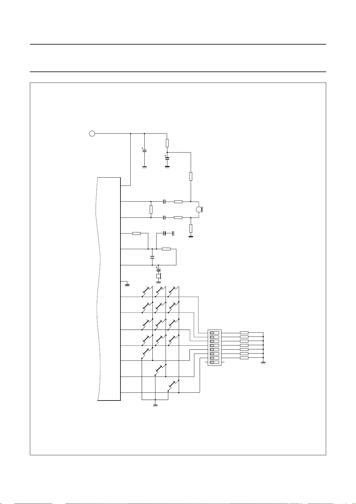
Philips Semiconductors Product specification
One-chip telephone ICs with speech,
dialler and ringer functions
handbook, full pagewidth
A
R
feed
100 µF
C
VCC
(10 V)
C
feed
V
CC
28
MIC−
27
R
E1
100 kΩ
C
R
GAR
MIC+
26
RX
25
GAR
24
QR
23
GND
22
tx3
C
ear
earpiece
8.2
kΩ
100 pF
18 nF
18 nF
C
IC1
R1
21
R2
20
R3
19
R4
18
C1
17
C2
16
C3
15
456
789
0#
/T
*
P->T
LNR/P
C
tx1
C
tx2
GARS
1 nF
R
GAR
47 kΩ
10 µF
(16 V)
1 kΩ
47 µF
(25 V)
312
R
R
tx1
22 kΩ
R
tx2
22 kΩ
R
R
micm
micp
1 kΩ
1 kΩ
MGT054
UBA2050(A); UBA2051(A;C)
+
MIC1
R
1 MΩ
(7×)
R
R
R
R
R
R
MBS
APT
PPS
PTS
MMS
FTSA
FTSB
16
1
2
3
4
5
6
7
8
MBS
15
APT
14
PPS
13
PTS
12
MMS
11
FTSA
10
FTSB
9
87654321
Fig.36 Application of the UBA2050 (continued from Fig.35).
2000 May 19 44
Page 45
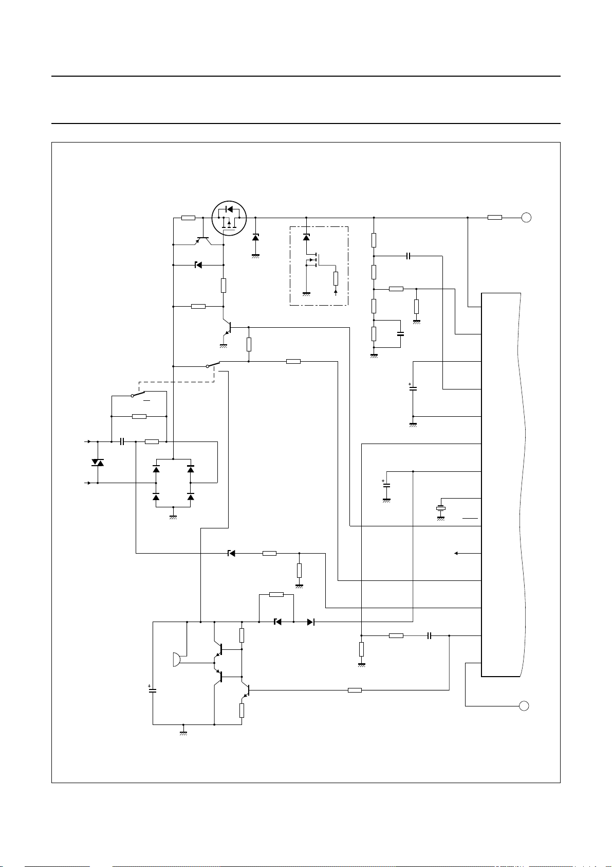
Philips Semiconductors Product specification
One-chip telephone ICs with speech,
dialler and ringer functions
470 kΩ
R3
TR1
BSP254A
Z1
220 kΩ
BZD23C
(10 V)
or
BZV85C
(10 V)
handbook, full pagewidth
A/B
BR211
D1
(220 V)
B/A
C
1 µF
S1-1
ring
C
R
trickle
15 MΩ
2.2 kΩ (2 W)
R
ring
D2
BAS11D3BAS11
D4
BAS11D5BAS11
R
prot
3.9 Ω
TR2
BZX79C
470 kΩ
BC558
Z2
(8.2 V)
R1
TR3
BF420
S1-2
C
R2
TR7
R
CSI
470 kΩ
UBA2050(A); UBA2051(A;C)
R
CC
SLPE
REG
AGC
DTMF
V
DD
XT AL
DP/FL
620 Ω
LN
1
2
3
IR
4
5
6
7
8
9
BZX79C
Z3
(4.3 V)
BSN254A
R
DMO
470 kΩ
DMO
R
130 kΩ
ast1
R
ast2
R
bal1
R
bal2
C
VDD
3.92 kΩ
R
392 Ω
130 Ω
820 Ω
ast3
C
REG
220 µF
(16 V)
C
ir
100 nF
C
220 nF
R
SLPE
20 Ω
bal
3.58 MHz
X1
A
IC1
Z4
BZX79C
(15 V)
R5
TR4
+
H1
ringer
22 µF
C
vrr
(35 V)
BC547
TR5
BC557
TR6
BC547
R
vol
100 kΩ
12 kΩ
R
FDI
470 kΩ
100 kΩ
BZX79C
R6
Z5
(16 V)
R4
BAS45
Fig.37 Application of the UBA2051 (continued in Fig.38).
2000 May 19 45
220 kΩ
D6
R
dtmf2
R
100 kΩ
mdy
2.74 kΩ
R
dtmf1
20 kΩ
C
dtmf
100 nF
DMO
MDY/TONE
DMO
CE/CSI
CE/FDI
10
11
12
13
C4
14
B
MGT055
Page 46
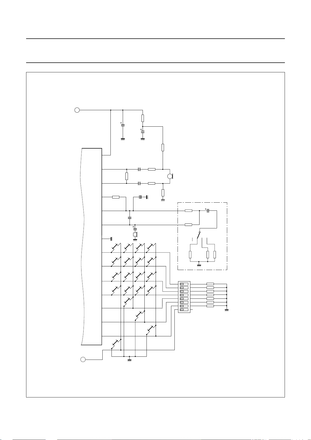
Philips Semiconductors Product specification
One-chip telephone ICs with speech,
dialler and ringer functions
handbook, full pagewidth
A
R
feed
100 µF
C
VCC
(10 V)
C
feed
V
CC
28
C
MIC−
27
R
100 kΩ
MEM
M1
M2
M3
tx3
R
E1
C
GAR
earpiece
P->T
MIC+
26
RX
25
GAR
24
QR
23
GND
22
IC1
R1
21
R2
20
R3
19
R4
18
C1
17
C2
16
C3
15
STORE
C4
B
tx1
18 nF
8.2
kΩ
C
tx2
18 nF
C
GARS
1 nF
100 pF
10 µF
C
ear
(16 V)
456
789
/T
0#
*
LNR/P
1 kΩ
47 µF
(25 V)
22 kΩ
22 kΩ
312
R
UBA2050(A); UBA2051(A;C)
R
1 kΩ
micp
R
tx1
R
tx2
R
micm
1 kΩ
MGT056
+
MIC1
1
2
3
4
5
6
7
8
R
22.1 kΩ
R
22.1 kΩ
R
gb1
18.2
kΩ
87654321
GAR1
GAR2
C
gb
1 µF
(50 V)
S3
kΩ
1 MΩ
(7×)
R
gb3
3.65
kΩ
GAIN BOOST
R
MBS
R
APT
R
PPS
R
PTS
R
MMS
R
FTSA
R
FTSB
R
gb2
7.15
16
MBS
15
APT
14
PPS
13
PTS
12
MMS
11
FTSA
10
FTSB
9
Fig.38 Application of the UBA2051 (continued from Fig.37).
2000 May 19 46
Page 47
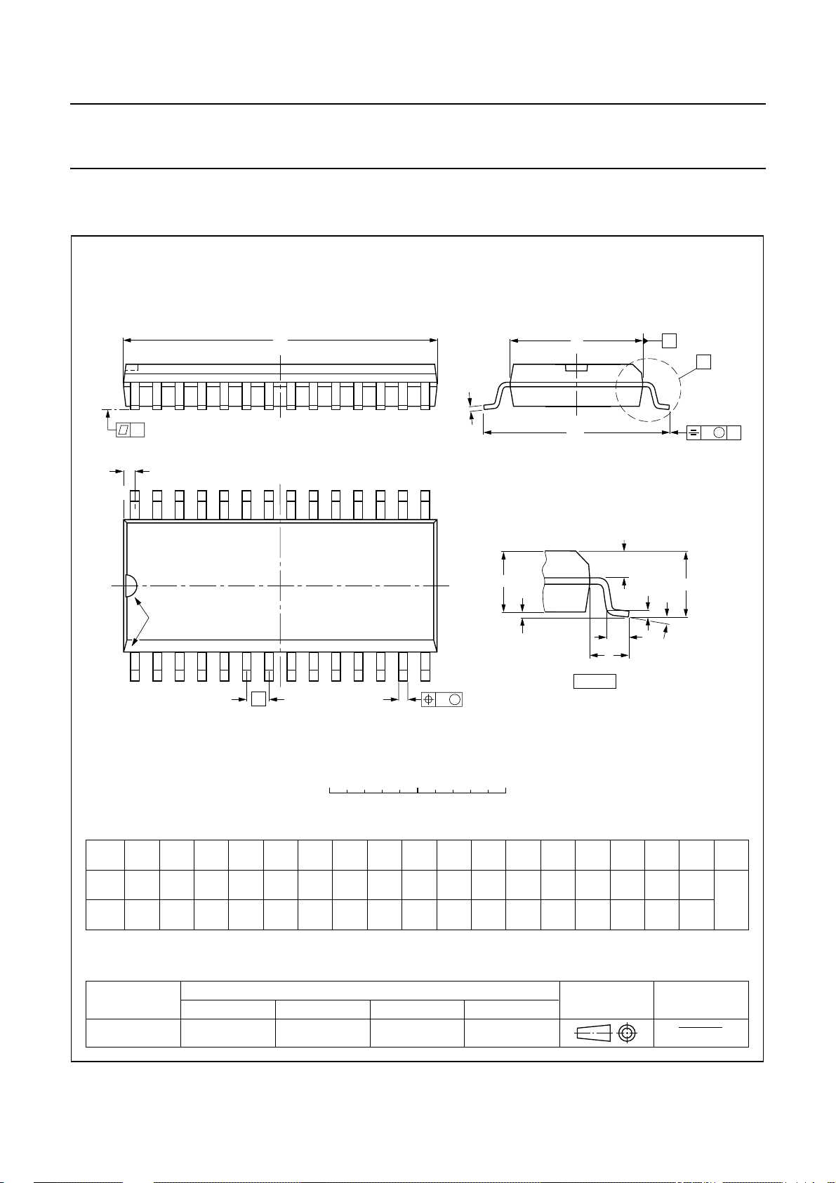
Philips Semiconductors Product specification
One-chip telephone ICs with speech,
dialler and ringer functions
PACKAGE OUTLINE
SO28: plastic small outline package; 28 leads; body width 7.5 mm
D
c
y
Z
28
15
UBA2050(A); UBA2051(A;C)
SOT136-1
E
H
E
A
X
v M
A
pin 1 index
1
e
0 5 10 mm
DIMENSIONS (inch dimensions are derived from the original mm dimensions)
mm
A
max.
2.65
0.10
A
1
0.30
0.10
0.012
0.004
A2A
2.45
2.25
0.096
0.089
0.25
0.01
b
3
p
0.49
0.32
0.36
0.23
0.019
0.013
0.014
0.009
UNIT
inches
Note
1. Plastic or metal protrusions of 0.15 mm maximum per side are not included.
(1)E(1) (1)
cD
18.1
7.6
17.7
7.4
0.71
0.30
0.69
0.29
14
w M
b
p
scale
eHELLpQ
1.27
0.050
10.65
10.00
0.419
0.394
1.4
0.055
Q
A
2
0.043
0.016
A
1.1
0.4
L
p
L
0.25 0.1
0.01
(A )
1
detail X
1.1
0.25
1.0
0.043
0.01
0.039
A
3
θ
ywv θ
Z
0.9
0.4
0.035
0.004
0.016
o
8
o
0
OUTLINE
VERSION
SOT136-1
IEC JEDEC EIAJ
075E06 MS-013
REFERENCES
2000 May 19 47
EUROPEAN
PROJECTION
ISSUE DATE
97-05-22
99-12-27
Page 48

Philips Semiconductors Product specification
One-chip telephone ICs with speech,
dialler and ringer functions
SOLDERING
Introduction to soldering surface mount packages
Thistextgives a very brief insight toacomplextechnology.
A more in-depth account of soldering ICs can be found in
our
“Data Handbook IC26; Integrated Circuit Packages”
(document order number 9398 652 90011).
There is no soldering method that is ideal for all surface
mount IC packages. Wavesoldering is notalways suitable
for surface mount ICs, or for printed-circuit boards with
high population densities. In these situations reflow
soldering is often used.
Reflow soldering
Reflow soldering requires solder paste (a suspension of
fine solder particles, flux and binding agent) to be applied
tothe printed-circuit board by screenprinting, stencilling or
pressure-syringe dispensing before package placement.
Several methods exist for reflowing; for example,
infrared/convection heating in a conveyor type oven.
Throughput times (preheating, soldering and cooling) vary
between 100 and 200 seconds depending on heating
method.
Typical reflow peak temperatures range from
215 to 250 °C. The top-surface temperature of the
packages should preferable be kept below 230 °C.
UBA2050(A); UBA2051(A;C)
• Use a double-wave soldering method comprising a
turbulent wave with high upward pressure followed by a
smooth laminar wave.
• For packages with leads on two sides and a pitch (e):
– larger than or equal to 1.27 mm, the footprint
longitudinal axis is preferred to be parallel to the
transport direction of the printed-circuit board;
– smaller than 1.27 mm, the footprint longitudinal axis
must be parallel to the transport direction of the
printed-circuit board.
The footprint must incorporate solder thieves at the
downstream end.
• Forpackageswithleads on four sides, the footprint must
be placed at a 45° angle to the transport direction of the
printed-circuit board. The footprint must incorporate
solder thieves downstream and at the side corners.
During placement and before soldering, the package must
be fixed with a droplet of adhesive. The adhesive can be
applied by screen printing, pin transfer or syringe
dispensing. The package can be soldered after the
adhesive is cured.
Typical dwell time is 4 seconds at 250 °C.
A mildly-activated flux will eliminate the need for removal
of corrosive residues in most applications.
Manual soldering
Wave soldering
Conventional single wave soldering is not recommended
forsurfacemountdevices (SMDs) or printed-circuit boards
with a high component density, as solder bridging and
non-wetting can present major problems.
To overcome these problems the double-wave soldering
method was specifically developed.
If wave soldering is used the following conditions must be
observed for optimal results:
Fix the component by first soldering two
diagonally-opposite end leads. Use a low voltage (24 V or
less) soldering iron applied to the flat part of the lead.
Contact time must be limited to 10 seconds at up to
300 °C.
When using a dedicated tool, all other leads can be
soldered in one operation within 2 to 5 seconds between
270 and 320 °C.
2000 May 19 48
Page 49

Philips Semiconductors Product specification
One-chip telephone ICs with speech,
UBA2050(A); UBA2051(A;C)
dialler and ringer functions
Suitability of surface mount IC packages for wave and reflow soldering methods
PACKAGE
BGA, LFBGA, SQFP, TFBGA not suitable suitable
HBCC, HLQFP, HSQFP, HSOP, HTQFP, HTSSOP, SMS not suitable
(3)
PLCC
LQFP, QFP, TQFP not recommended
SSOP, TSSOP, VSO not recommended
Notes
1. All surface mount (SMD) packages are moisture sensitive. Depending upon the moisture content, the maximum
2. These packages are not suitable for wave soldering as a solder joint between the printed-circuit board and heatsink
3. If wave soldering is considered, then the package must be placed at a 45° angle to the solder wave direction.
4. Wave soldering is only suitable for LQFP, TQFP and QFP packages with a pitch (e) equal to or larger than 0.8 mm;
5. Wave soldering is only suitable for SSOP and TSSOP packages with a pitch (e) equal to or larger than 0.65 mm; it is
, SO, SOJ suitable suitable
temperature (with respect to time) and body size of the package, there is a risk that internal or external package
cracks may occur due to vaporization of the moisture in them (the so called popcorn effect). For details, refer to the
Drypack information in the
(at bottom version) can not be achieved, and as solder may stick to the heatsink (on top version).
The package footprint must incorporate solder thieves downstream and at the side corners.
it is definitely not suitable for packages with a pitch (e) equal to or smaller than 0.65 mm.
definitely not suitable for packages with a pitch (e) equal to or smaller than 0.5 mm.
“Data Handbook IC26; Integrated Circuit Packages; Section: Packing Methods”
SOLDERING METHOD
WAVE REFLOW
(2)
(3)(4)
(5)
suitable
suitable
suitable
(1)
.
2000 May 19 49
Page 50

Philips Semiconductors Product specification
One-chip telephone ICs with speech,
UBA2050(A); UBA2051(A;C)
dialler and ringer functions
DATA SHEET STATUS
DATA SHEET STATUS
Objective specification Development This data sheet contains the design target or goal specifications for
Preliminary specification Qualification This data sheet contains preliminary data, and supplementary data will be
Product specification Production This data sheet contains final specifications. Philips Semiconductors
Note
1. Please consult the most recently issued data sheet before initiating or completing a design.
DEFINITIONS
Short-form specification The data in a short-form
specification is extracted from a full data sheet with the
same type number and title. For detailed information see
the relevant data sheet or data handbook.
Limiting values definition Limiting values given are in
accordance with the Absolute Maximum Rating System
(IEC 60134). Stress above one or more of the limiting
values may cause permanent damage to the device.
These are stress ratings only and operation of the device
attheseor at any other conditionsabovethosegiven in the
Characteristics sections of the specification is not implied.
Exposure to limiting values for extended periods may
affect device reliability.
Application information Applications that are
described herein for any of these products are for
illustrative purposes only. Philips Semiconductors make
norepresentationorwarrantythatsuch applications will be
suitable for the specified use without further testing or
modification.
PRODUCT
STATUS
DEFINITIONS
product development. Specification may change in any manner without
notice.
published at a later date. Philips Semiconductors reserves the right to
make changes at any time without notice in order to improve design and
supply the best possible product.
reserves the right to make changes at any time without notice in order to
improve design and supply the best possible product.
DISCLAIMERS
Life support applications These products are not
designed for use in life support appliances, devices, or
systems where malfunction of these products can
reasonably be expected to result in personalinjury. Philips
Semiconductorscustomersusingorsellingtheseproducts
for use in such applications do so at their own risk and
agree to fully indemnify Philips Semiconductors for any
damages resulting from such application.
Right to make changes Philips Semiconductors
reserves the right to make changes, without notice, in the
products, including circuits, standard cells, and/or
software, described or contained herein in order to
improve design and/or performance. Philips
Semiconductors assumes no responsibility or liability for
theuseofany of these products, conveys no licence ortitle
under any patent, copyright, or mask work right to these
products,and makes no representations orwarrantiesthat
these products are free from patent, copyright, or mask
work right infringement, unless otherwise specified.
(1)
2000 May 19 50
Page 51

Philips Semiconductors Product specification
One-chip telephone ICs with speech,
dialler and ringer functions
NOTES
UBA2050(A); UBA2051(A;C)
2000 May 19 51
Page 52

Philips Semiconductors – a w orldwide compan y
Argentina: see South America
Australia: 3 Figtree Drive, HOMEBUSH, NSW 2140,
Tel. +61 2 9704 8141, Fax. +61 2 9704 8139
Austria: Computerstr. 6, A-1101 WIEN, P.O. Box 213,
Tel. +43 1 60 101 1248, Fax. +43 1 60 101 1210
Belarus: Hotel Minsk Business Center, Bld. 3, r. 1211, Volodarski Str. 6,
220050 MINSK, Tel. +375 172 20 0733, Fax. +375 172 20 0773
Belgium: see The Netherlands
Brazil: see South America
Bulgaria: Philips Bulgaria Ltd., Energoproject, 15th floor,
51 James Bourchier Blvd., 1407 SOFIA,
Tel. +359 2 68 9211, Fax. +359 2 68 9102
Canada: PHILIPS SEMICONDUCTORS/COMPONENTS,
Tel. +1 800 234 7381, Fax. +1 800 943 0087
China/Hong Kong: 501 Hong Kong Industrial Technology Centre,
72 Tat Chee Avenue, Kowloon Tong, HONG KONG,
Tel. +852 2319 7888, Fax. +852 2319 7700
Colombia: see South America
Czech Republic: see Austria
Denmark: Sydhavnsgade 23, 1780 COPENHAGEN V,
Tel. +45 33 29 3333, Fax. +45 33 29 3905
Finland: Sinikalliontie 3, FIN-02630 ESPOO,
Tel. +358 9 615 800, Fax. +358 9 6158 0920
France: 51 Rue Carnot, BP317, 92156 SURESNES Cedex,
Tel. +33 1 4099 6161, Fax. +33 1 4099 6427
Germany: Hammerbrookstraße 69, D-20097 HAMBURG,
Tel. +49 40 2353 60, Fax. +49 40 2353 6300
Hungary: see Austria
India: Philips INDIA Ltd, Band Box Building, 2nd floor,
254-D, Dr. Annie Besant Road, Worli, MUMBAI 400 025,
Tel. +91 22 493 8541, Fax. +91 22 493 0966
Indonesia: PT Philips Development Corporation,Semiconductors Division,
Gedung Philips, Jl. Buncit Raya Kav.99-100, JAKARTA 12510,
Tel. +62 21 794 0040 ext. 2501, Fax. +62 21 794 0080
Ireland: Newstead, Clonskeagh, DUBLIN 14,
Tel. +353 1 7640 000, Fax. +353 1 7640 200
Israel: RAPAC Electronics, 7 Kehilat Saloniki St, PO Box 18053,
TEL AVIV 61180, Tel. +972 3 645 0444, Fax. +972 3 649 1007
Italy: PHILIPS SEMICONDUCTORS, Via Casati, 23 - 20052 MONZA (MI),
Tel. +39 039 203 6838, Fax +39 039 203 6800
Japan: Philips Bldg 13-37, Kohnan 2-chome, Minato-ku,
TOKYO 108-8507, Tel. +81 3 3740 5130, Fax. +81 3 3740 5057
Korea: Philips House, 260-199 Itaewon-dong, Yongsan-ku, SEOUL,
Tel. +82 2 709 1412, Fax. +82 2 709 1415
Malaysia: No. 76 Jalan Universiti, 46200 PETALING JAYA, SELANGOR,
Tel. +60 3 750 5214, Fax. +60 3 757 4880
Mexico: 5900 Gateway East, Suite 200, EL PASO, TEXAS 79905,
Tel. +9-5 800 234 7381, Fax +9-5 800 943 0087
Middle East: see Italy
Netherlands: Postbus 90050, 5600 PB EINDHOVEN, Bldg. VB,
Tel. +31 40 27 82785, Fax. +31 40 27 88399
New Zealand: 2 Wagener Place, C.P.O. Box 1041, AUCKLAND,
Tel. +64 9 849 4160, Fax. +64 9 849 7811
Norway: Box 1, Manglerud 0612, OSLO,
Tel. +47 22 74 8000, Fax. +47 22 74 8341
Pakistan: see Singapore
Philippines: Philips Semiconductors Philippines Inc.,
106 Valero St. Salcedo Village, P.O. Box 2108 MCC, MAKATI,
Metro MANILA, Tel. +63 2 816 6380, Fax. +63 2 817 3474
Poland: Al.Jerozolimskie 195 B, 02-222 WARSAW,
Tel. +48 22 5710 000, Fax. +48 22 5710 001
Portugal: see Spain
Romania: see Italy
Russia: Philips Russia, Ul. Usatcheva 35A, 119048 MOSCOW,
Tel. +7 095 755 6918, Fax. +7 095 755 6919
Singapore: Lorong 1, Toa Payoh, SINGAPORE 319762,
Tel. +65 350 2538, Fax. +65 251 6500
Slovakia: see Austria
Slovenia: see Italy
South Africa: S.A. PHILIPS Pty Ltd., 195-215 Main Road Martindale,
2092 JOHANNESBURG, P.O. Box 58088 Newville 2114,
Tel. +27 11 471 5401, Fax. +27 11 471 5398
South America: Al. Vicente Pinzon, 173, 6th floor,
04547-130 SÃO PAULO, SP, Brazil,
Tel. +55 11 821 2333, Fax. +55 11 821 2382
Spain: Balmes 22, 08007 BARCELONA,
Tel. +34 93 301 6312, Fax. +34 93 301 4107
Sweden: Kottbygatan 7, Akalla, S-16485 STOCKHOLM,
Tel. +46 8 5985 2000, Fax. +46 8 5985 2745
Switzerland: Allmendstrasse 140, CH-8027 ZÜRICH,
Tel. +41 1 488 2741 Fax. +41 1 488 3263
Taiwan: Philips Semiconductors, 6F, No. 96, Chien Kuo N. Rd., Sec. 1,
TAIPEI, Taiwan Tel. +886 2 2134 2886, Fax. +886 2 2134 2874
Thailand: PHILIPS ELECTRONICS (THAILAND) Ltd.,
209/2 Sanpavuth-Bangna Road Prakanong, BANGKOK 10260,
Tel. +66 2 745 4090, Fax. +66 2 398 0793
Turkey: Yukari Dudullu, Org. San. Blg., 2.Cad. Nr. 28 81260 Umraniye,
ISTANBUL, Tel. +90 216 522 1500, Fax. +90 216 522 1813
Ukraine: PHILIPS UKRAINE, 4 Patrice Lumumba str., Building B, Floor 7,
252042 KIEV, Tel. +380 44 264 2776, Fax. +380 44 268 0461
United Kingdom: Philips Semiconductors Ltd., 276 Bath Road, Hayes,
MIDDLESEX UB3 5BX, Tel. +44 208 730 5000, Fax. +44 208 754 8421
United States: 811 East Arques Avenue, SUNNYVALE, CA 94088-3409,
Tel. +1 800 234 7381, Fax. +1 800 943 0087
Uruguay: see South America
Vietnam: see Singapore
Yugoslavia: PHILIPS, Trg N. Pasica 5/v, 11000 BEOGRAD,
Tel. +381 11 3341 299, Fax.+381 11 3342 553
For all other countries apply to: Philips Semiconductors,
International Marketing & Sales Communications, Building BE-p, P.O. Box 218,
5600 MD EINDHOVEN, The Netherlands, Fax. +31 40 27 24825
© Philips Electronics N.V. SCA
All rights are reserved. Reproduction in whole or in part is prohibited without the prior written consent of the copyright owner.
The information presented in this document does not form part of any quotation or contract, is believed to be accurate and reliable and may be changed
without notice. No liability will be accepted by the publisher for any consequence of its use. Publication thereof does not convey nor imply any license
under patent- or other industrial or intellectual property rights.
2000
Internet: http://www.semiconductors.philips.com
69
Printed in The Netherlands 403502/02/pp52 Date of release: 2000 May 19 Document order number: 9397 750 06723
 Loading...