

Page 1
Ultrasonic sensor UB2000-F54-E5-V15
Technical data
General specifications
Sensing range 80 ... 2000 mm
Adjustment range 100 ... 2000 mm
Dead band 0 ... 80 mm
Standard target plate 100 mm x 100 mm
Transducer frequency approx. 175 kHz
Response delay ≤ 150 ms
Indicators/operating means
Model Number
UB2000-F54-E5-V15
Single head system
Features
• Switch output
• 5 different output functions can be
set
•Program input
• Synchronization options
• Deactivation option
• Temperature compensation
Diagrams
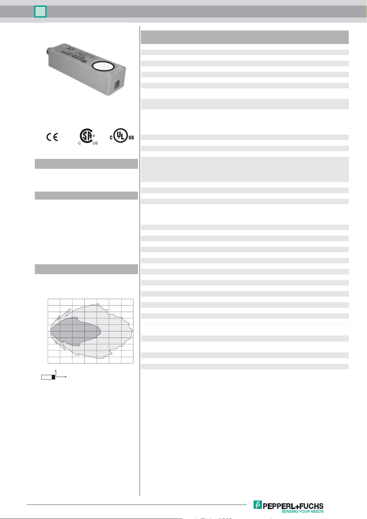
Characteristic response curve
Distance Y [m]
0.5
0.4
0.3
0.2
0.1
0.0
-0.1
-0.2
-0.3
-0.4
-0.5
0 0.5 1 1.5 2 2.5 3 3.5
Curve 1: flat surface 100 mm x 100 mm
Curve 2: round bar, Ø 25 mm
2
Y
X
1
Distance X [m]
LED green solid green: monitoring system
LED yellow indication of the switching state
LED red flashing:
Electrical specifications
Operating voltage U
No-load supply current I
Input/Output
B
0
Synchronization 1 synchronous input
Synchronization frequency
Common mode operation ≤ 33 Hz
Multiplex operation ≤ 33 / n Hz, n = number of sensors
Input
Input type 1 program input,
Output
Output type 1 switch output E5, PNP, NO/NC
Rated operating current I
Voltage drop U
Repeat accuracy ≤ 1 % of full-scale value
d
e
Switching frequency f max. 3 Hz
Range hysteresis H ≤ 1 % of the set operating distance
Temperature influence ± 1.5 % of full-scale value
Ambient conditions
Ambient temperature -25 ... 70 °C (-13 ... 158 °F)
Storage temperature -40 ... 85 °C (-40 ... 185 °F)
Mechanical specifications
Connection type Connector M12 x 1 , 5-pin
Degree of protection IP65
Material
Housing ABS
Transducer epoxy resin/hollow glass sphere mixture; polyurethane foam
Mass 100 g
Compliance with standards and
directives
Standard conformity
Standards EN 60947-5-2:2007 + A1:2012
Approvals and certificates
UL approval cULus Listed, General Purpose
CSA approval cCSAus Listed, General Purpose
CCC approval CCC approval / marking not required for products rated ≤36 V
green flashing: program function
flashing: program function object detected
normal mode: error
Program function: no object detected
permanently:
Program mode, object uncertain
10 ... 30 V DC , ripple 10 %
≤ 55 mA
0-level: -U
1-level: +4 V...+U
input impedance: > 12 KOhm
...+1 V
B
SS
B
synchronization pulse: 0,1 ... 28 ms
switching point A1: -U
+U
B
input impedance: > 4.7 kΩ, program pulse: ≥ 1 s
... +1 V, switching point A2: +4 V ...
B
200 mA , short-circuit/overload protected
≤ 3 V
IEC 60947-5-2:2007 + A1:2012
Release date: 2016-04-13 11:25 Date of issue: 2016-04-13 108160_eng.xml
Refer to “General Notes Relating to Pepperl+Fuchs Product Information”.
1
Page 2
Ultrasonic sensor UB2000-F54-E5-V15
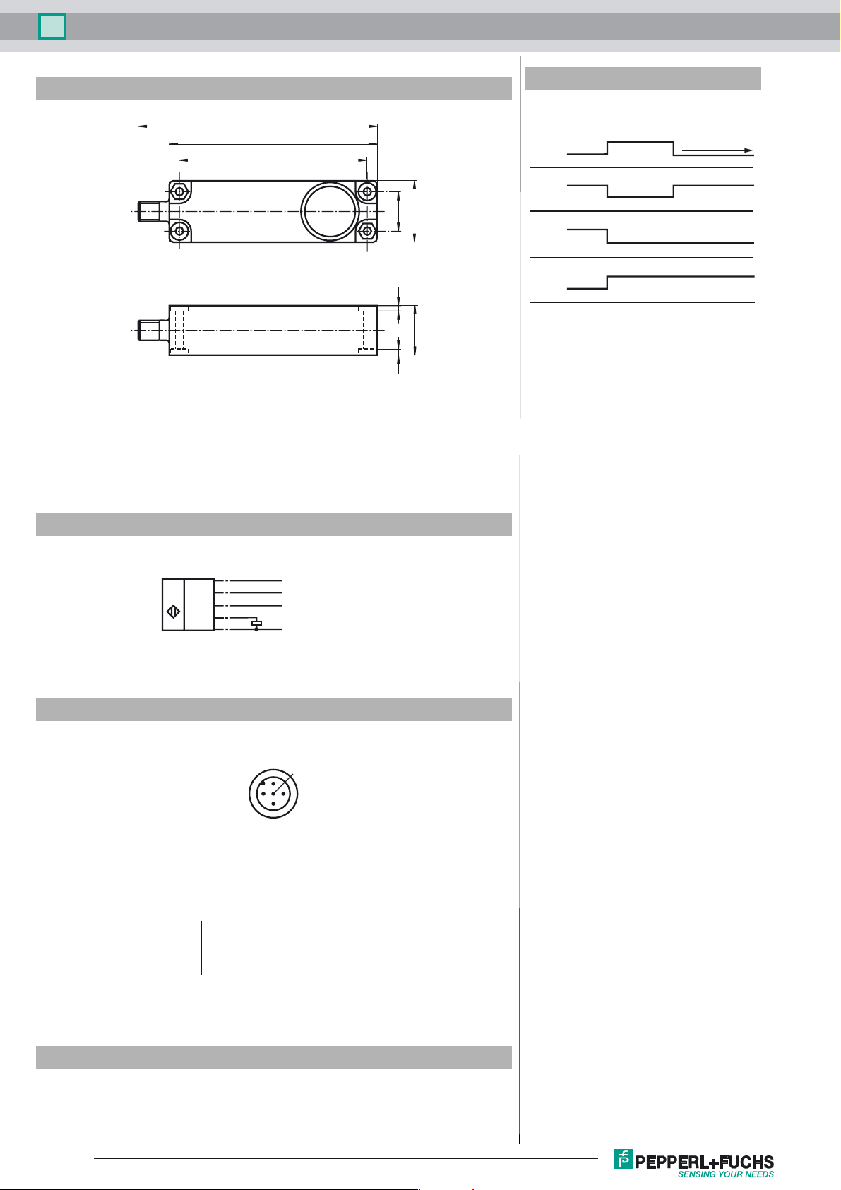
Dimensions
Bore hole and countersinking
for screws/hexagon M4
120
105
94
21
3.5 3.5
Additional Information
Programmable output modes
1. Window mode, normally open mode
A1 < A2:
A1
2. Window mode, normally closed mode
A2 < A1:
32
3. One switch point, normally open mode
A1 -> ∞:
A2
A2
4. One switch point, normally closed mode
A2 -> ∞:
A1
5. A1 -> ∞, A2 -> ∞: Object presence detection mode
25
Object detected: Switch output closed
No object detected: Switch output open
object distance
A2
A1
Electrical Connection
Standard symbol/Connections:
(version E5, pnp)
U
Wire colors in accordance with EN 60947-5-2.
Pinout
Wire colors in accordance with EN 60947-5-2
1 BN
2 WH
3 BU
4 BK
5 GY
(BN)
1
(WH)
2
(GY)
5
(BK)
4
(BU)
3
2
+ U
Program input
Sync. input
Switch output
- U
1
5
B
B
4
3
(brown)
(white)
(blue)
(black)
(gray)
Accessories
UB-PROG2
Programming unit
V15-G-2M-PVC
Female cordset, M12, 5-pin, PVC cable
Refer to “General Notes Relating to Pepperl+Fuchs Product Information”.
2
Release date: 2016-04-13 11:25 Date of issue: 2016-04-13 108160_eng.xml
Page 3

Ultrasonic sensor UB2000-F54-E5-V15
Synchronisation
The sensor features a synchronisation input for the suppression of mutual interference. If this input is not used, the sensor will
operate using an internally generated clock rate. The synchronisation of multiple sensors can be realised as follows:
External synchronisation
The sensor can be synchronised by the external application of a square wave voltage. A synchronisation pulse at the synchronisation input starts a measuring cycle. The pulse must have a duration greater than 100 µs. The measuring cycle starts with
the falling edge of a synchronisation pulse. A low level > 1 s or an open synchronisation input will result in the normal operation
of the sensor. A high level at the synchronisation input disables the sensor.
Two operating modes are available
1. Multiple sensors can be controlled by the same synchronisation signal. The sensors are synchronised.
2. The synchronisation pulses are sent cyclically to individual sensors. The sensors operate in multiplex mode.
Internal synchronisation
The synchronisation connections of up to 5 sensors capable of internal synchronisation are connected to one another. When
power is applied, these sensors will operate in multiplex mode. The response delay increases according to the number of sensors to be synchronised. Synchronisation cannot be performed during TEACH-IN and vice versa. The sensors must be operated
in an unsynchronised manner to teach the switching point.
Note:
If the option for synchronisation is not used, the synchronisation input has to be connected to ground (0V) or the sensor has to
be operated via a V1 cable connector (4-pin).
Adjusting of switching points
The ultrasonic sensor features a switch output with two teachable switching points. These are set by applying the supply voltage
-U
or +UB to the TEACH-IN input. The supply voltage must be applied to the TEACH-IN input for at least 1 s. LEDs indicate
B
whether the sensor has recognised the target during the TEACH-IN procedure. Switching point A1 is taught with -U
+UB.
Five different output functions can be set
1. Window mode, normally-open function
2. Window mode, normally-closed function
3. One switching point, normally-open function
4. One switching point, normally-closed function
5. Detection of object presence
, A2 with
B
TEACH-IN window mode, normally-open function
- Set target to near switching point
- TEACH-IN switching point A1 with -U
B
- Set target to far switching point
- TEACH-IN switching point A2 with +U
B
TEACH-IN window mode, normally-closed function
- Set target to near switching point
- TEACH-IN switching point A2 with +U
B
- Set target to far switching point
- TEACH-IN switching point A1 with -U
B
TEACH-IN one switching point, normally-open function
- Set target to near switching point
- TEACH-IN switching point A2 with +U
B
- Cover sensor with hand or remove all objects from sensing range
- TEACH-IN switching point A1 with -U
B
TEACH-IN one switching point, normally-closed function
- Set target to near switching point
- TEACH-IN switching point A1 with -U
B
- Cover sensor with hand or remove all objects from sensing range
- TEACH-IN switching point A2 with +U
B
TEACH-IN detection of object presence
- Cover sensor with hand or remove all objects from sensing range
- TEACH-IN switching point A1 with -U
- TEACH-IN switching point A2 with +U
B
B
Default setting of switching points
A1 = unusable area
A2 = nominal sensing range
LED Displays
Release date: 2016-04-13 11:25 Date of issue: 2016-04-13 108160_eng.xml
Refer to “General Notes Relating to Pepperl+Fuchs Product Information”.
3
Page 4

Ultrasonic sensor UB2000-F54-E5-V15
Displays in dependence on operating mode Red LED Yellow LED Green LED
TEACH-IN switching point:
Object detected
No object detected
Object uncertain (TEACH-IN invalid)
Normal operation off switching
Fault flashes previous state off
off
flashes
on
flashes
off
off
state
flashes
flashes
flashes
on
Release date: 2016-04-13 11:25 Date of issue: 2016-04-13 108160_eng.xml
Refer to “General Notes Relating to Pepperl+Fuchs Product Information”.
4
 Loading...