

U893BSE
1.3 GHz Prescaler for PLL’s in TV, CATV and SAT TV Tuners
Technology: Bipolar
Features
D
D
Extrem low current consumption (typ. 18 mA)
D
Output harmonics strongly reduced
D
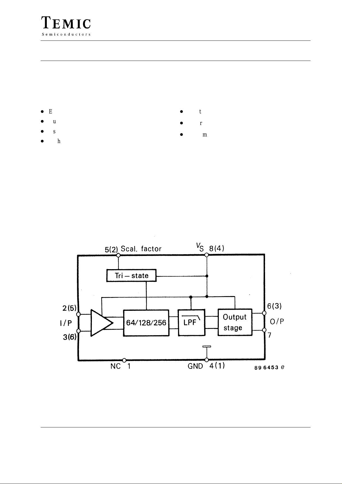
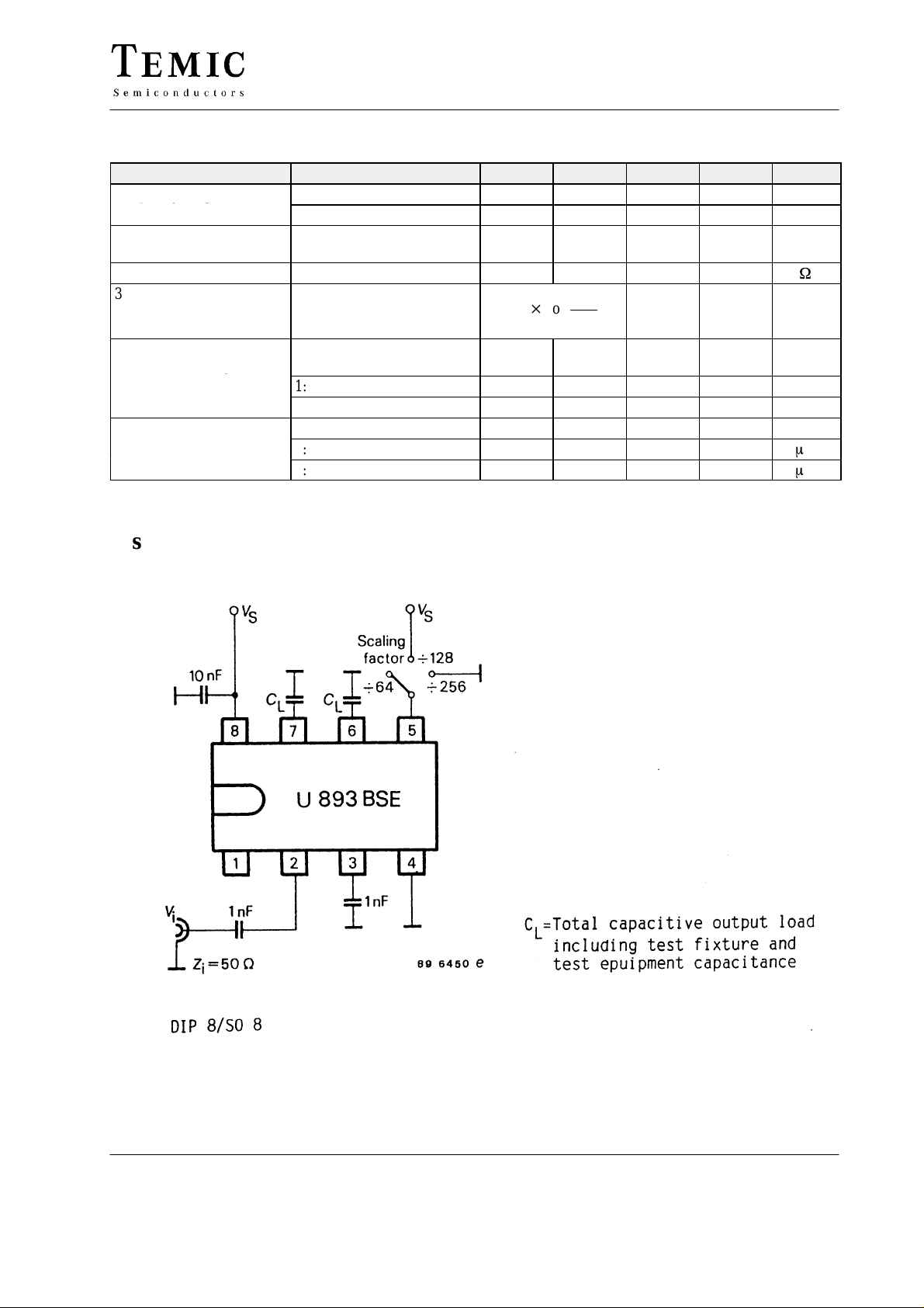
3 scaling factors 64/128/256 programmable at Pin 5
D
High input sensitivity
Case
8 pin dual inline plastic (U893BSE)
8 pin SO plastic (U893BSE-FP)
6 pin SIP plastic (U893BSE-SP)
Emitter follower output stage
D
Electrostatic protection according to MIL–STD. 883
D
Pin compatible to U833BSE
Block Diagram
TELEFUNKEN Semiconductors
Rev . A1, 23-Aug-96
1 (7)
U893BSE
Pin Configuration
Pin Function (DIP8, SO8)
1 n.c.
2, 3 Input
4 Ground
5 Switch 64/128/256
6, 7 Output
8 V
S
Pin Function (SIP6)
1 Ground
2 Switch 64/128/256
3 Output
4 V
5, 6 Input
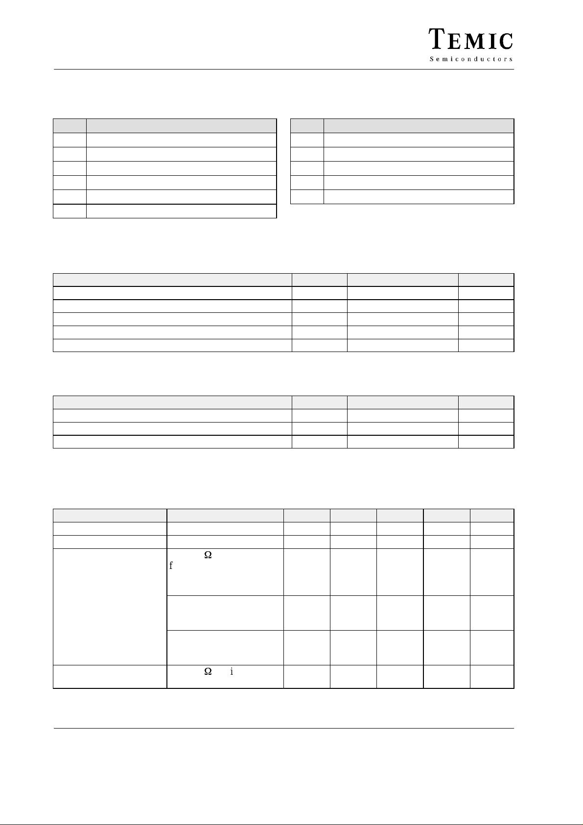
Absolute Maximum Ratings
Reference point Pin 4 (1), unless otherwise specified
Parameters Symbol Value Unit
Supply voltage Pin 8 (4) V
Input voltage range Pin 2, 3, 5 (2, 5, 6) V
Junction temperature T
Ambient temperature range T
Storage temperature range T
Thermal Resistance
Parameters Symbol Maximum Unit
Junction ambient DIP8 R
SIP6 R
SO8 R
S
i
j
amb
stg
thJA
thJA
thJA
S
6 V
0 to V
S
V
125 °C
–25 to +85 °C
–40 to +125 °C
100 K/W
100 K/W
175 K/W
Electrical Characteristics
V
= 4.5 to 5.5 V, T
S
Parameters Test Conditions / Pin Symbol Min. Typ. Max. Unit
Supply voltage range Pin 8 (4) V
Supply current VS = 5 V Pin 8 (4) I
Input sensitivity
Large signal compatibility RG = 50
1)
RMS-voltage calculated from the measured available power
2 (7)
= 0 to 70 °C, referred to test circuit, unless otherwise specified
amb
1)
RG = 50
f
i
W
= 70 to 1100 MHz
Pin 2, 3 (5,
6)
fi = 1100 to 1200 MHz
Pin 2, 3 (5,
6)
fi = 1200 to 1300 MHz
Pin 2, 3 (5,
6)
W
Pin 2, 3 (5,
6)
S
S
v
i
v
i
v
i
V
i
4.5 5.5 V
21 25 mA
10 mV
15 mV
20 mV
300 mV
TELEFUNKEN Semiconductors
Rev . A1, 23-Aug-96
Parameters Test Conditions / Pin Symbol Min Typ Max Unit
qyg
g()
g
Frequency range f
f
Emitter follower output
Voltage swing each output
fi ≤ 1000 MHz, CL = 13 pF,
SF = 1:64 Pin 6, 7 (3)
Output impedance Pin 6, 7 (3) Z
3rd order harmonics
suppression
fi = 700 to 900 MHz,
C
= 13 pF, SF = 1:64
L
Pin 6, 7 (3)
Switching voltage for
scaling factor (SF)
1:64 Pin 5 (2) V
1:128 V
1:256 V
Switching current V
= 5 V Pin 5 (2)
S
1:128 VSF = 5 V I
1:256 VSF = 0 V I
imin
imax
V
O
O
20 log
SF
SF
SF
SF
SF
U893BSE
70 MHz
1300 MHz
0.6 0.7 V
200
V
O3f
V
O1f
VS – 0.5 V
–30 dB
open
0 0.3 V
150
–150
m
m
pp
W
A
A
Test Circuits
TELEFUNKEN Semiconductors
Rev . A1, 23-Aug-96
3 (7)

U893BSE
Output Circuit
Emitter follower output
4 (7)
TELEFUNKEN Semiconductors
Rev . A1, 23-Aug-96

Input Sensitivity
U893BSE
Dimensions in mm
TELEFUNKEN Semiconductors
Rev . A1, 23-Aug-96
5 (7)

U893BSE
Dimensions in mm
6 (7)
TELEFUNKEN Semiconductors
Rev . A1, 23-Aug-96

U893BSE
Ozone Depleting Substances Policy Statement
It is the policy of TEMIC TELEFUNKEN microelectronic GmbH to
1. Meet all present and future national and international statutory requirements.
2. Regularly and continuously improve the performance of our products, processes, distribution and operating systems
with respect to their impact on the health and safety of our employees and the public, as well as their impact on
the environment.
It is particular concern to control or eliminate releases of those substances into the atmosphere which are known as
ozone depleting substances (ODSs).
The Montreal Protocol ( 1987) and its London Amendments (1990 ) intend to severely restrict the use of ODSs and
forbid their use within the next ten years. Various national and international initiatives are pressing for an earlier ban
on these substances.
TEMIC TELEFUNKEN microelectronic GmbH semiconductor division has been able to use its policy of
continuous improvements to eliminate the use of ODSs listed in the following documents.
1. Annex A, B and list of transitional substances of the Montreal Protocol and the London Amendments respectively
2. Class I and II ozone depleting substances in the Clean Air Act Amendments of 1990 by the Environmental
Protection Agency (EPA) in the USA
3. Council Decision 88/540/EEC and 91/690/EEC Annex A, B and C (transitional substances) respectively.
TEMIC can certify that our semiconductors are not manufactured with ozone depleting substances and do not contain
such substances.
We reserve the right to make changes to improve technical design and may do so without further notice.
Parameters can vary in different applications. All operating parameters must be validated for each customer
application by the customer. Should the buyer use TEMIC products for any unintended or unauthorized
application, the buyer shall indemnify TEMIC against all claims, costs, damages, and expenses, arising out of,
directly or indirectly, any claim of personal damage, injury or death associated with such unintended or
unauthorized use.
TEMIC TELEFUNKEN microelectronic GmbH, P.O.B. 3535, D-74025 Heilbronn, Germany
Telephone: 49 (0)7131 67 2831, Fax number: 49 (0)7131 67 2423
TELEFUNKEN Semiconductors
Rev . A1, 23-Aug-96
7 (7)
 Loading...