

Page 1
rail-to-rail input/output 8 MHz operational amplifiers
Features
■ Rail-to-rail input and output
■ Wide bandwidth
■ Low power consumption: 820 µA typ
■ Unity gain stability
■ High output current: 35 mA
■ Operating range from 2.5 to 5.5 V
■ Low input bias current, 1 pA typ
■ ESD internal protection ≥ 5kV
■ Latch-up immunity
Applications
TSV912H, TSV912AH
High temperature
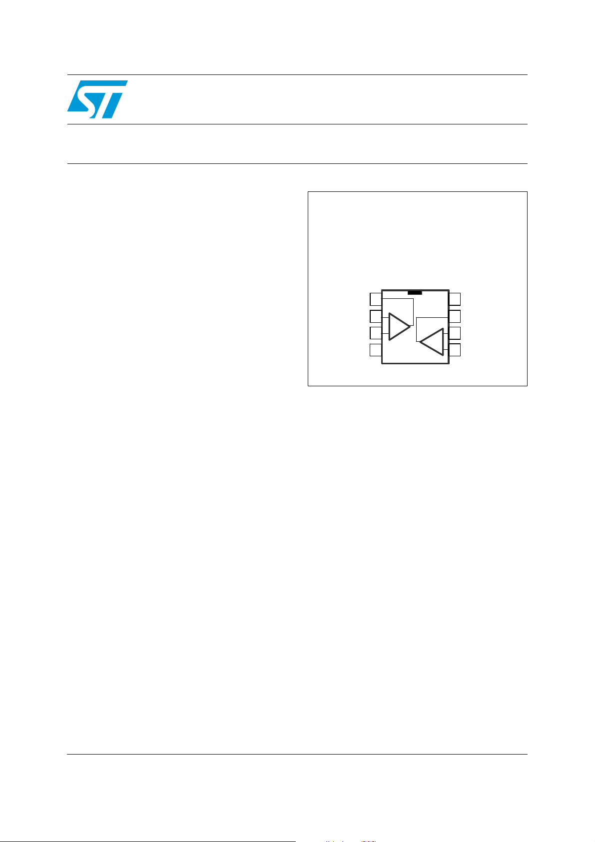
Pin connections
(top view)
SO-8
Out1
Out1
In1-
In1-
In1+
In1+
V
V
CC-
CC-
1
1
_
_
2
2
+
+
3
3
4
4
8
8
V
V
CC+
CC+
7
7
Out2
Out2
_
_
+
+
In2-
In2-
6
6
In2+
In2+
5
5
■ Automotive products
Description
The TSV912H and TSV912AH operational
amplifiers offer low voltage operation and rail-torail input and output.
The devices feature an excellent speed/power
consumption ratio, offering an 8 MHz gainbandwidth product while consuming only 1.1 mA
maximum at 5 V. They are unity gain stable and
feature an ultra-low input bias current.
The TSV912H is a high temperature version of
the TSV912, and can operate from -40°C to
+150°C with unique characteristics. Its main
target applications are automotive, but the device
is also ideal for sensor interfaces, batterysupplied and portable applications, as well as
active filtering.
July 2010 Doc ID 17688 Rev 1 1/16
www.st.com
16
Page 2
Absolute maximum ratings and operating conditions TSV912H, TSV912AH
1 Absolute maximum ratings and operating conditions
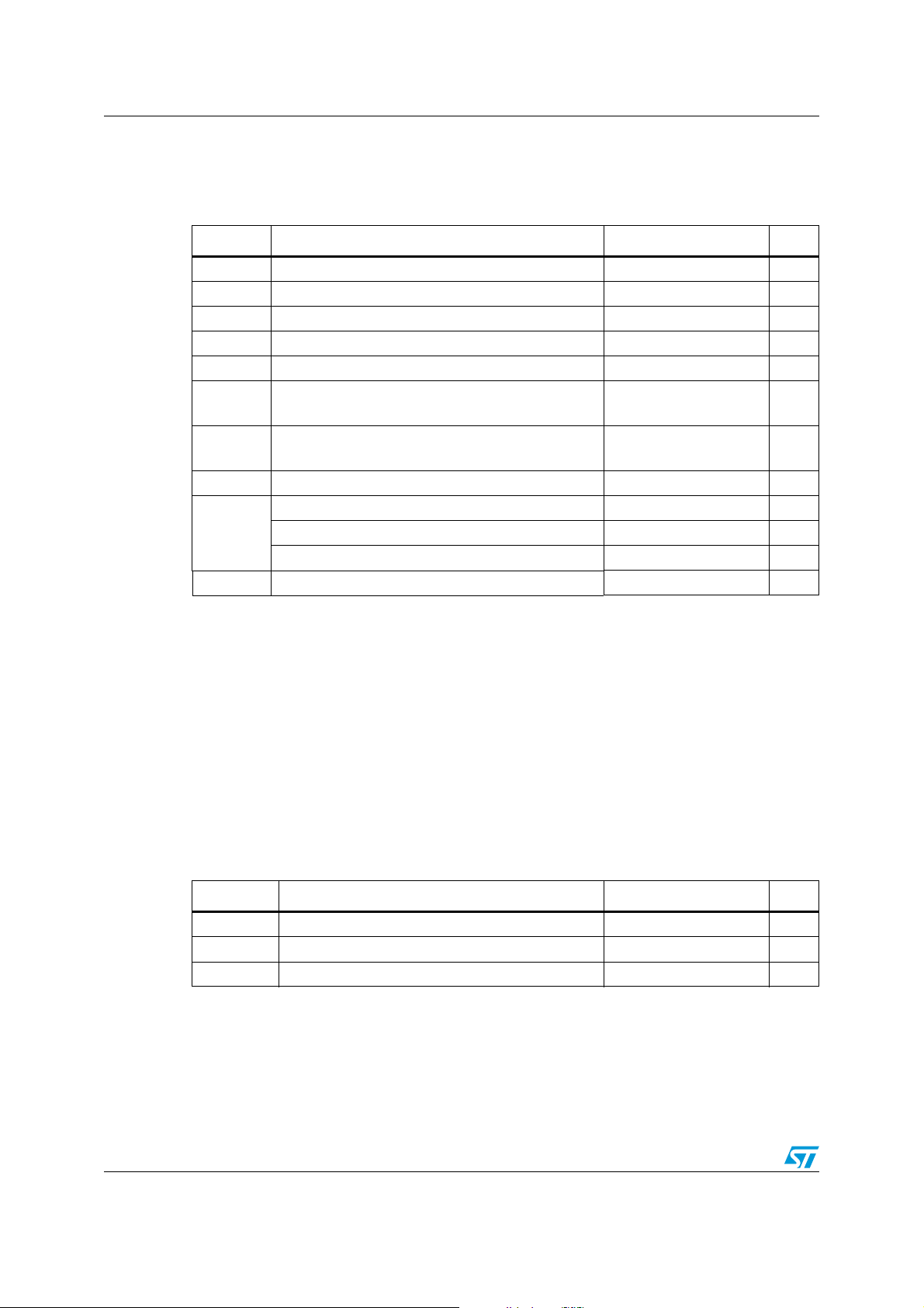
Table 1. Absolute maximum ratings
Symbol Parameter Value Unit
(3)
(4)
(1)
(V
CC+
(8)
- V
(2)
(7)
CC-
(9)
)
V
CC-
6V
±V
CC
-0.2 to V
+0.2 V
CC+
V
10 mA
(5) (6)
125
(5) (6)
°C/W
°C/W
5kV
400 V
1500 V
V
CC
V
V
I
in
T
stg
R
thja
R
thjc
T
Supply voltage
Differential input voltage
id
Input voltage
in
Input current
Storage temperature -65 to +150 °C
Thermal resistance junction to ambient
SO-8
Thermal resistance junction to case
SO-8 40
Maximum junction temperature 160 °C
j
HBM: human body model
ESD
MM: machine model
CDM: charged device model
Latch-up immunity 200 mA
1. All voltage values, except differential voltage, are with respect to network ground terminal.
2. Differential voltages are the non-inverting input terminal with respect to the inverting input terminal.
3. VCC-Vin must not exceed 6 V.
4. Input current must be limited by a resistor in series with the inputs.
5. Short-circuits can cause excessive heating and destructive dissipation.
are typical values.
6. R
th
7. Human body model: a 100 pF capacitor is charged to the specified voltage, then discharged through a
1.5kΩ resistor between two pins of the device. This is done for all couples of connected pin combinations
while the other pins are floating.
8. Machine model: a 200 pF capacitor is charged to the specified voltage, then discharged directly between
two pins of the device with no external series resistor (internal resistor < 5 Ω). This is done for all couples of
connected pin combinations while the other pins are floating.
9. Charged device model: all pins and the package are charged together to the specified voltage and then
discharged directly to the ground through only one pin. This is done for all pins.
Table 2. Operating conditions
Symbol Parameter Value Unit
T
V
V
CC
icm
oper
Supply voltage (V
CC+
- V
) 2.5 to 5.5 V
CC-
Common mode input voltage range V
Operating free-air temperature range -40 to +150 °C
2/16 Doc ID 17688 Rev 1
-0.1 to V
CC-
+0.1 V
CC+
Page 3
TSV912H, TSV912AH Electrical characteristics
2 Electrical characteristics
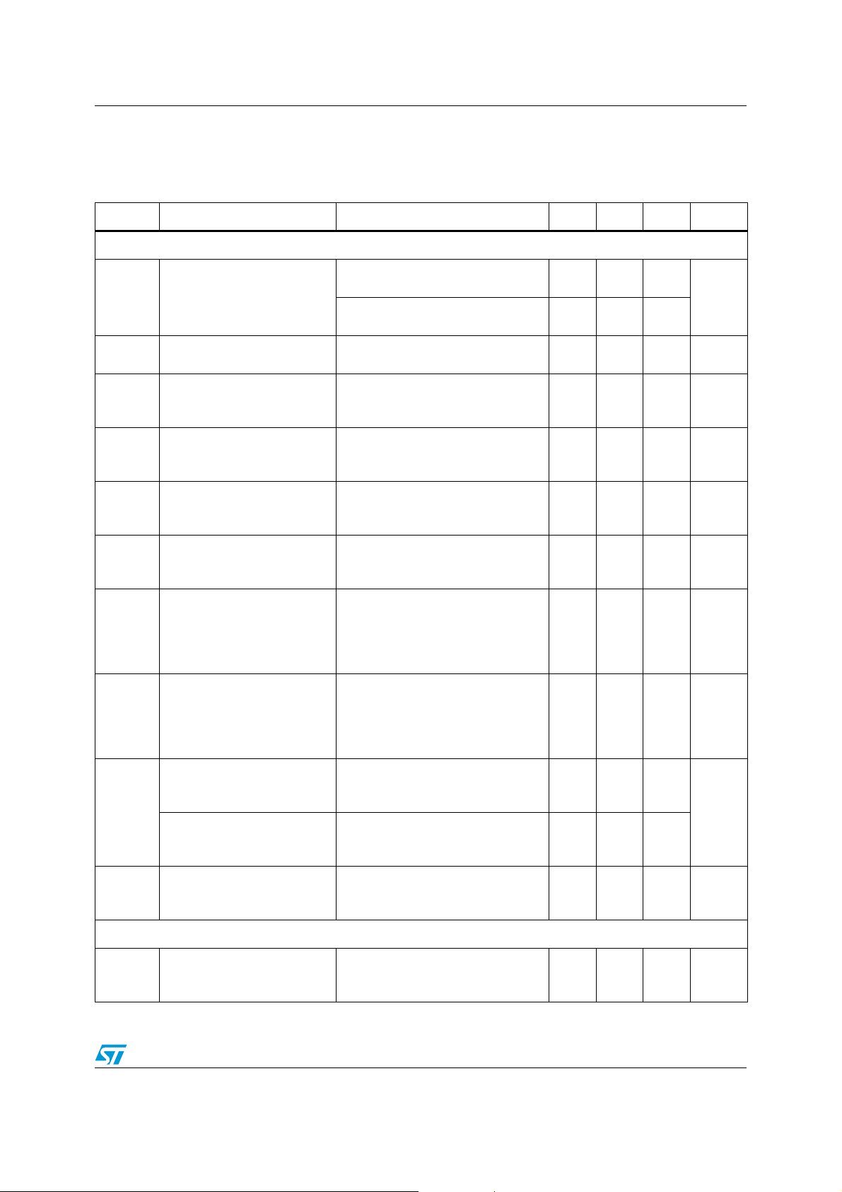
Table 3. Electrical characteristics at V
Symbol Parameter Conditions Min. Typ. Max. Unit
DC performance
to V
/2, T = 25°C (unless otherwise specified)
CC
= +2.5 V with V
CC+
CC-
= 0 V, V
= VCC/2, RL connected
icm
V
DV
CMR
A
Input offset voltage
io
/DT Input offset voltage drift
io
Input offset current
I
io
I
Input bias current
ib
Common mode rejection ratio
20 log (ΔV
Large signal voltage gain
vd
/ΔVio)
ic
VCC-VOHHigh level output voltage
V
I
I
Low level output voltage
OL
I
sink
out
I
source
Supply current (per operator)
CC
AC performance
TSV912H, T=25°C
TSV912H, T
< T < T
min
TSV912AH, T=25°C
TSV912AH, T
< T < T
min
-40°C < T < +125°C
+125°C < T < +150°C
V
out=VCC
/2
T=25°C
< T < T
T
min
V
out=VCC
max
/2
T=25°C
T
< T < T
min
0V to 2.5V, V
max
out
= 1.25V
T=25°C
< T < T
T
min
R
= 10kΩ, V
L
max
= 0.5V to 2V
out
T=25°C
< T < T
T
min
max
RL=10kΩ, T=25°C
RL=10kΩ, T
min
< T < T
RL=600Ω, T=25°C
RL=600Ω, T
R
=10kΩ, T=25°C
L
RL=10kΩ, T
min
min
< T < T
< T < T
RL=600Ω, T=25°C
R
=600Ω, T
L
V
= 2.5V
out
< T < T
min
T=25°C
T
< T < T
min
V
= 0V
out
max
T=25°C
< T < T
T
min
No load, V
max
out=VCC
/2
T=25°C
< T < T
T
min
max
max
max
max
max
max
max
58
53
80
70
18
14
18
14
0.1 4.5
7.5
1.5
3
2
20
110
μV/°C
(1)
5
110
(1)
5
75 dB
89 dB
15
40
60
45
150
250
15
40
60
45
150
250
32
35
0.78 1.1
1.1
mV
pA
nA
pA
nA
mV
mV
mA
mA
GBP Gain bandwidth product
RL=2kΩ, CL=100pF, f =100kHz
T=25°C
< T < T
T
min
max
8
4
Doc ID 17688 Rev 1 3/16
MHz
Page 4
Electrical characteristics TSV912H, TSV912AH
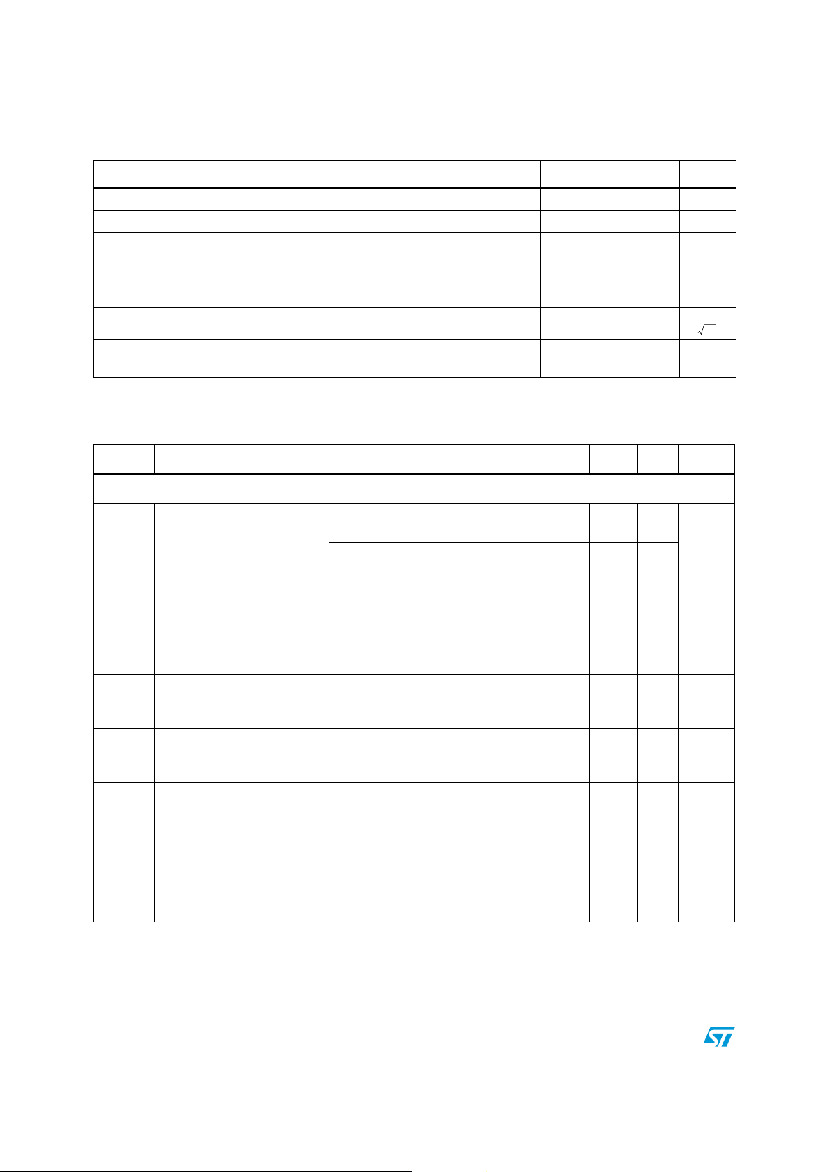
Table 3. Electrical characteristics at V
to V
/2, T = 25°C (unless otherwise specified) (continued)
CC
= +2.5 V with V
CC+
CC-
= 0 V, V
= VCC/2, RL connected
icm
Symbol Parameter Conditions Min. Typ. Max. Unit
F
Unity gain frequency RL=2kΩ, CL= 100pF 7.2 MHz
u
φm Phase margin RL=2kΩ, CL= 100pF 45 Degrees
G
Gain margin RL=2kΩ, CL= 100pF 8 dB
m
RL=2kΩ, CL=100pF, Av=1
SR Slew rate
e
Equivalent input noise voltage f= 10kHz 21
n
THD+enTotal harmonic distortion
1. Guaranteed by design.
Table 4. Electrical characteristics at V
to V
/2, T = 25°C (unless otherwise specified)
CC
T=25°C
< T < T
T
min
max
G=1, f=1kHz, R
=(VCC+1)/2, V
V
icm
= +3.3 V with V
CC+
=2kΩ, Bw= 22kHz,
L
=1.1V
out
pp
CC-
= 0 V, V
4.5
3.5
0.001 %
= VCC/2, RL connected
icm
Symbol Parameter Conditions Min. Typ. Max. Unit
DC performance
V
DV
I
I
CMR
A
V
CC-VOH
Input offset voltage
io
Input offset voltage drift
io
Input offset current
io
Input bias current
ib
Common mode rejection ratio
20 log (ΔVic/ΔVio)
Large signal voltage gain
vd
High level output voltage
TSV912H, T=25°C
TSV912H, T
< T < T
min
TSV912AH, T=25°C
TSV912AH, T
min
< T < T
-40°C < T < +125°C
+125°C < T < +150°C
V
out=VCC
/2
T=25°C
< T < T
T
min
V
out=VCC
max
/2
T=25°C
< T < T
T
min
0V to 3.3V, V
max
out
= 1.65V
T=25°C
< T < T
T
min
R
=10kΩ, V
L
max
= 0.5V to 2.8V
out
T=25°C
< T < T
T
min
R
=10kΩ, T=25°C
L
=10kΩ, T
R
L
max
min
< T < T
RL=600Ω, T=25°C
RL=600Ω, T
< T < T
min
max
max
60
55
80
70
max
max
0.1 4.5
7.5
1.5
3
2
20
110
μV/°C
(1)
5
110
(1)
5
78 dB
90 dB
15
40
60
45
150
250
V/μs
nV
-----------Hz
mV
pA
nA
pA
nA
mV
4/16 Doc ID 17688 Rev 1
Page 5
TSV912H, TSV912AH Electrical characteristics
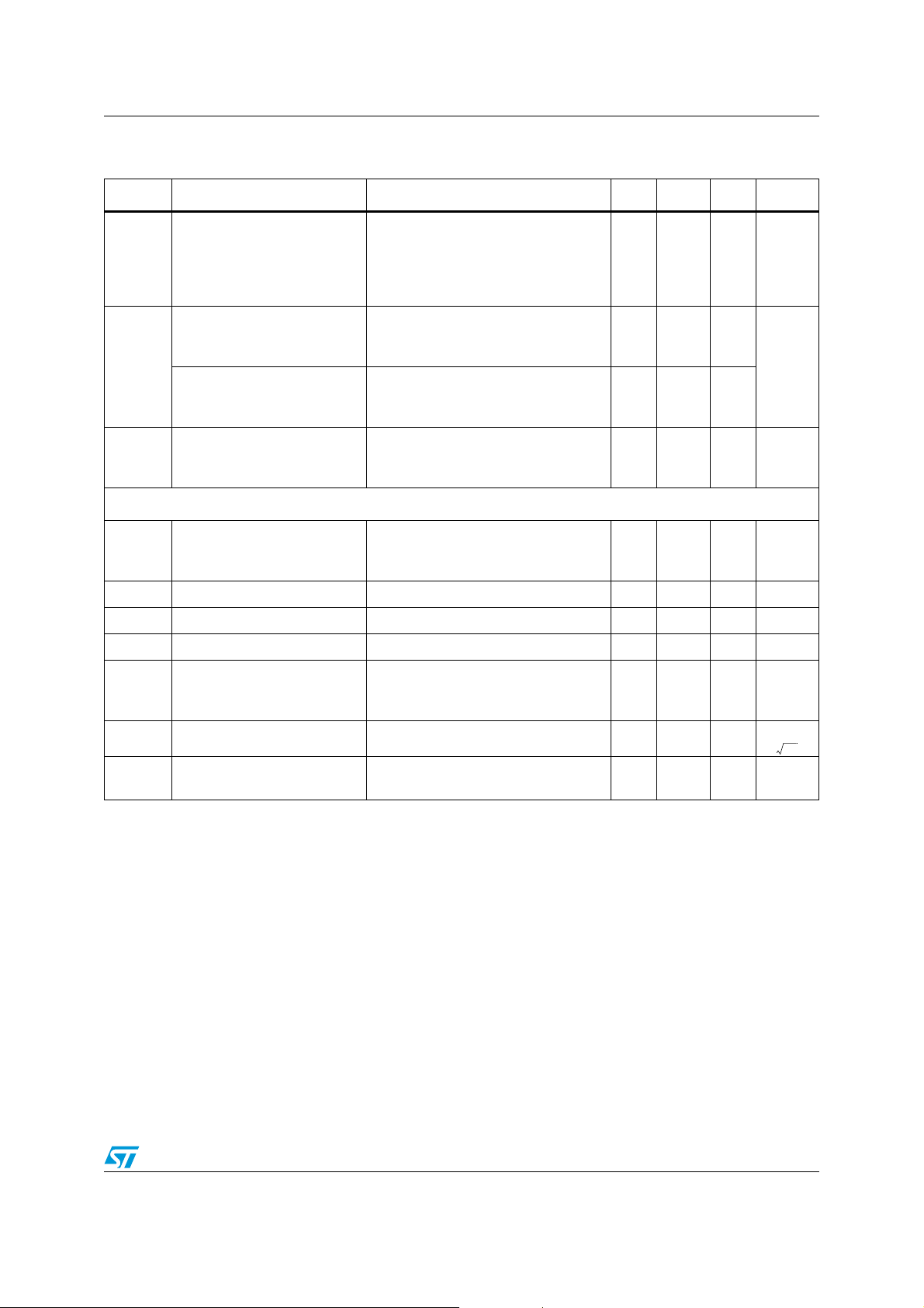
Table 4. Electrical characteristics at V
to V
/2, T = 25°C (unless otherwise specified) (continued)
CC
= +3.3 V with V
CC+
CC-
= 0 V, V
= VCC/2, RL connected
icm
Symbol Parameter Conditions Min. Typ. Max. Unit
R
=10kΩ, T=25°C
L
=10kΩ, T
R
V
Low level output voltage
OL
L
min
< T < T
max
RL=600Ω, T=25°C
=600Ω, T
R
L
V
= 3.3V
I
sink
I
out
I
source
out
T=25°C
< T < T
T
min
V
= 0V
out
T=25°C
< T < T
T
min
No load, V
I
Supply current (per operator)
CC
T=25°C
< T < T
T
min
< T < T
min
max
max
out=VCC
max
max
18
14
18
14
/2
15
40
60
45
150
250
32
35
0.8 1.1
1.1
AC performance
R
=2kΩ, CL= 100pF, f = 100kHz,
GBP Gain bandwidth product
Unity gain frequency RL= 2kΩ, CL=100pF 7.2 MHz
F
u
φm Phase margin R
G
Gain margin RL=2kΩ, CL=100pF 8 dB
m
SR Slew rate
Equivalent input noise voltage f= 10kHz 21
e
n
THD+e
1. Guaranteed by design.
Total harmonic distortion
n
L
T=25°C
< T < T
T
min
=2kΩ, CL=100pF 45 Degrees
L
R
=2kΩ, CL= 100pF, Av=1,
L
max
T=25°C
< T < T
T
min
G=1, f=1kHz, R
=(VCC+1)/2, V
V
icm
max
=2kΩ, BW= 22kHz,
L
=1.9Vpp,
out
8
4.2
4.5
3.5
0.0007 %
mV
mA
mA
MHz
V/μs
nV
-----------Hz
Doc ID 17688 Rev 1 5/16
Page 6
Electrical characteristics TSV912H, TSV912AH
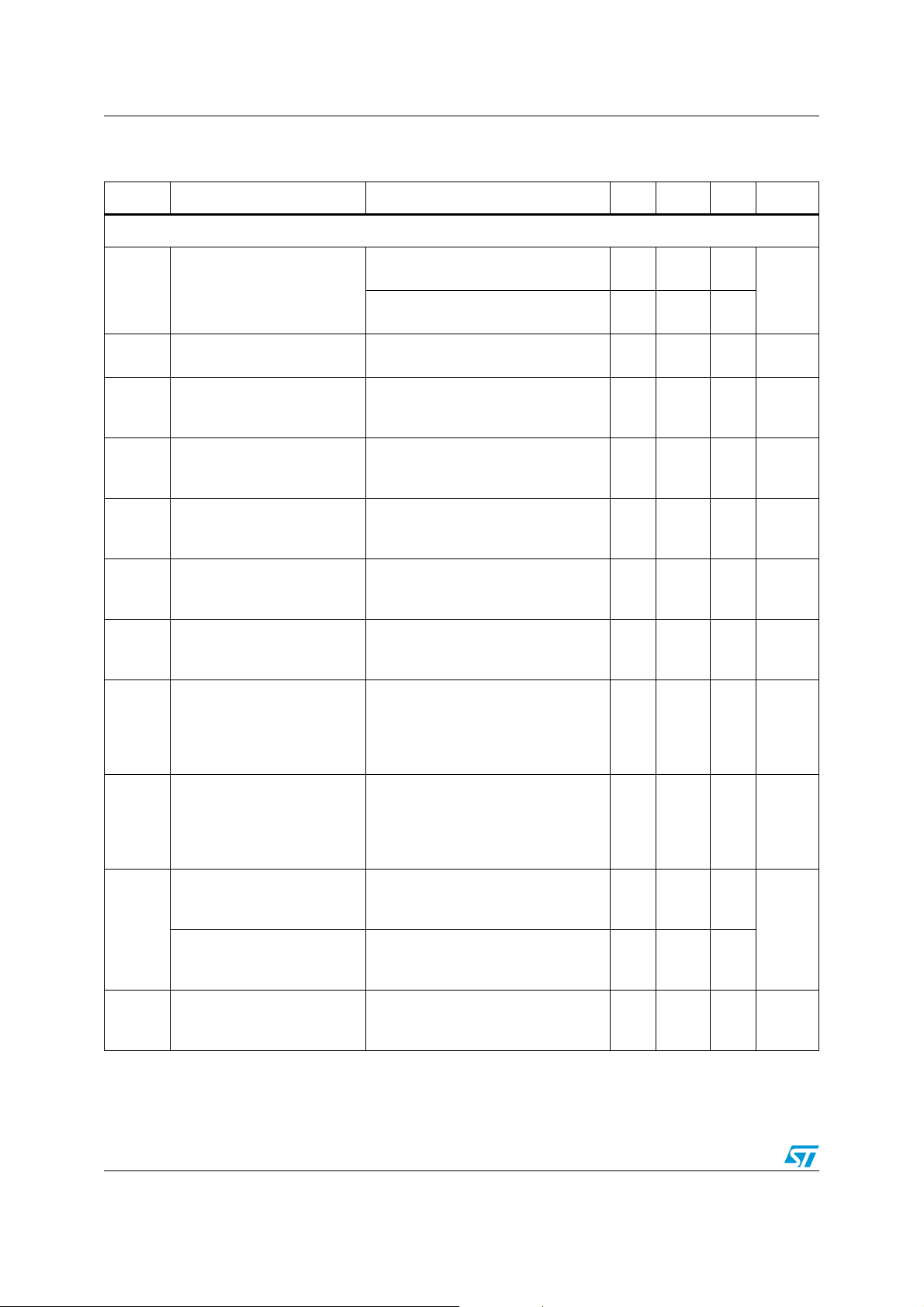
Table 5. Electrical characteristics at V
V
/2, full temperature range (unless otherwise specified)
CC
= +5 V with V
CC+
CC-
= 0 V, V
= VCC/2, RL connected to
icm
Symbol Parameter Conditions Min. Typ. Max. Unit
DC performance
V
io
DV
I
io
I
ib
CMR
SVR
A
vd
Input offset voltage
Input offset voltage drift
io
Input offset current
Input bias current
Common mode rejection ratio
20 log (ΔV
/ΔVio)
ic
Supply voltage rejection ratio
20 log (ΔV
CC
/ΔVio)
Large signal voltage gain
TSV912H, T=25°C
TSV912H, T
min
< T < T
TSV912AH, T=25°C
TSV912AH, T
min
< T < T
-40°C < T < +125°C
+125°C < T < +150°C
V
out=VCC
/2
T=25°C
T
< T < T
min
V
out=VCC
max
/2
T=25°C
< T < T
T
min
0V to 5V, V
max
out
= 2.5V
T=25°C
< T < T
T
min
= 2.5 to 5V
V
CC
max
T=25°C
< T < T
T
min
RL=10kΩ, V
max
= 0.5V to 4.5V
out
T=25°C
< T < T
T
min
R
=10kΩ, T=25°C
L
RL=10kΩ, T
max
min
< T < T
max
max
62
58
70
65
80
70
max
0.1 4.5
7.5
1.5
3
2
20
110
μV/°C
(1)
5
110
(1)
5
82 dB
86 dB
91 dB
15
40
60
VCC-VOHHigh level output voltage
RL=600Ω, T=25°C
=600Ω, T
R
L
min
< T < T
max
RL=10kΩ, T=25°C
R
=10kΩ, T
V
Low level output voltage
OL
L
< T < T
min
max
RL=600Ω, T=25°C
R
I
I
I
sink
out
I
source
Supply current (per operator)
CC
=600Ω, T
L
V
= 5V
out
T=25°C
< Top < T
T
min
V
= 0V
out
T=25°C
< Top < T
T
min
No load, V
T=25°C
< Top < T
T
min
out
< T < T
min
max
max
= 2.5V
max
max
18
14
18
14
45
150
250
15
40
60
45
150
250
32
35
0.82 1.1
1.1
mV
pA
nA
pA
nA
mV
mV
mA
mA
6/16 Doc ID 17688 Rev 1
Page 7
TSV912H, TSV912AH Electrical characteristics
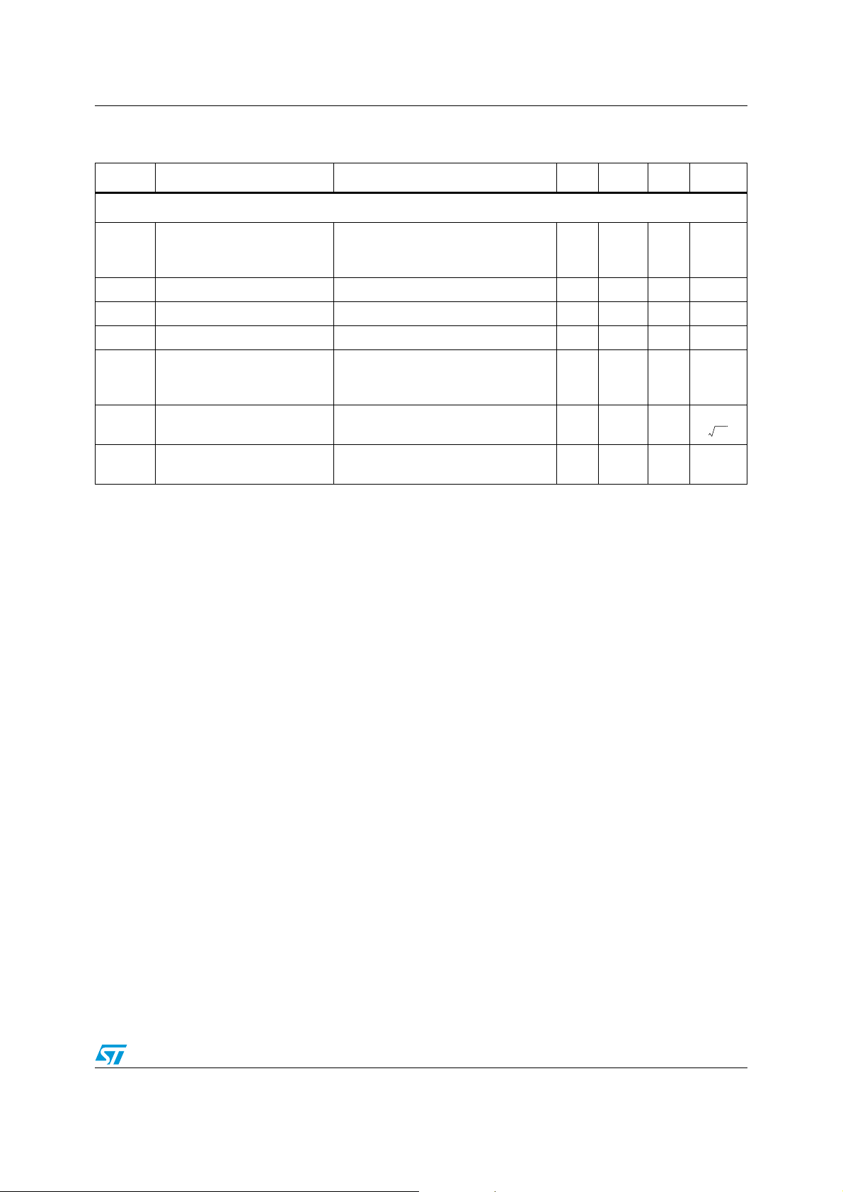
Table 5. Electrical characteristics at V
V
/2, full temperature range (unless otherwise specified) (continued)
CC
= +5 V with V
CC+
CC-
= 0 V, V
= VCC/2, RL connected to
icm
Symbol Parameter Conditions Min. Typ. Max. Unit
AC performance
R
=2kΩ, CL= 100pF, f = 100kHz
GBP Gain bandwidth product
F
Unity gain frequency RL = 2kΩ, CL=100pF 7.5 MHz
u
φm Phase margin R
G
Gain margin RL = 2kΩ, CL=100pF 8 dB
m
SR Slew rate
e
Equivalent input noise voltage
n
THD+e
1. Guaranteed by design.
Total harmonic distortion
n
L
T=25°C
< Top < T
T
min
= 2kΩ, CL=100pF 45 Degrees
L
R
=2kΩ, CL= 100pF, AV=1
L
max
T=25°C
< Top < T
T
min
max
f=1kHz
f=10kHz
G=1, f=1kHz, R
=(VCC+1)/2, V
V
icm
=2kΩ, Bw= 22kHz,
L
=3.6V
out
pp
8
4.5
4.5
3.5
27
21
0.0004 %
MHz
V/μs
nV
-----------Hz
Doc ID 17688 Rev 1 7/16
Page 8
Electrical characteristics TSV912H, TSV912AH
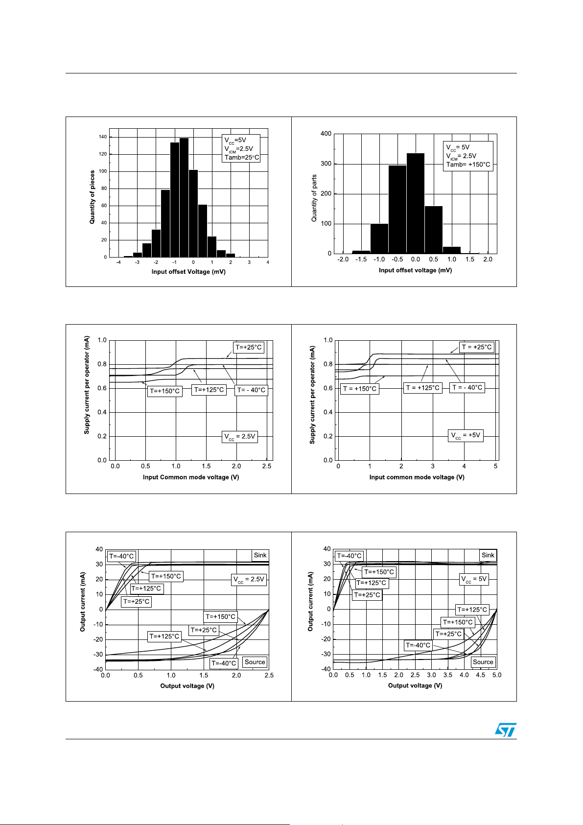
Figure 1. Input offset voltage distribution at
T= 25°C
Figure 3. Supply current vs. input common-
mode voltage at V
CC
=2.5V
Figure 2. Input offset voltage distribution at
T = 150° C
Figure 4. Supply current vs. input common-
mode voltage at VCC=5V
Figure 5. Output current vs. output voltage at
V
CC
Figure 6. Output current vs. output voltage at
=2.5V
8/16 Doc ID 17688 Rev 1
VCC=5V
Page 9
TSV912H, TSV912AH Electrical characteristics
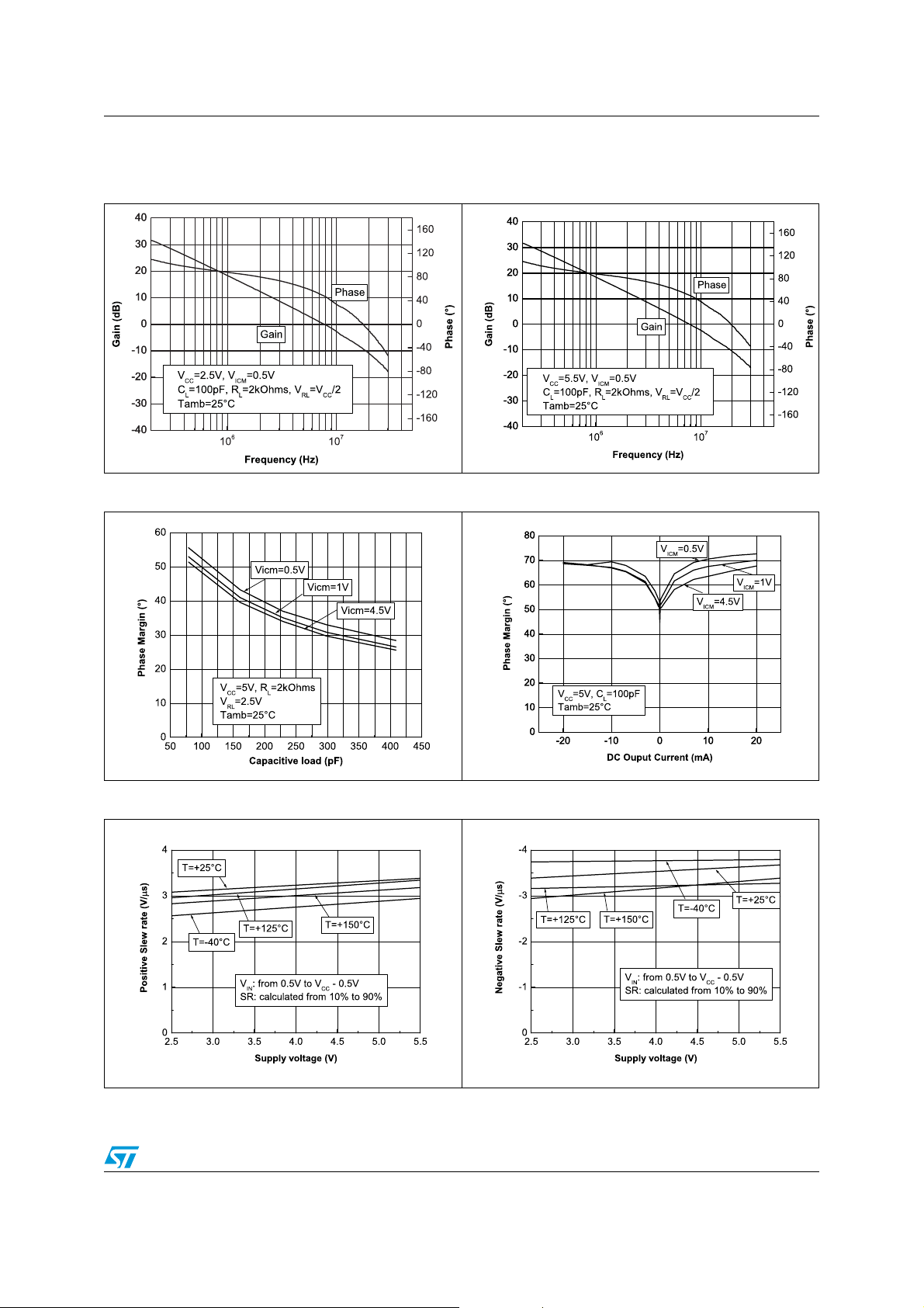
Figure 7. Voltage gain and phase vs
frequency at V
V
= 0.5 V
icm
= 2.5 V and
CC
Figure 8. Voltage gain and phase vs
frequency at V
V
=0.5V
icm
= 5.5V and
CC
Figure 9. Phase margin vs. capacitive load Figure 10. Phase margin vs. output current
Figure 11. Positive slew rate Figure 12. Negative slew rate
Doc ID 17688 Rev 1 9/16
Page 10
Electrical characteristics TSV912H, TSV912AH
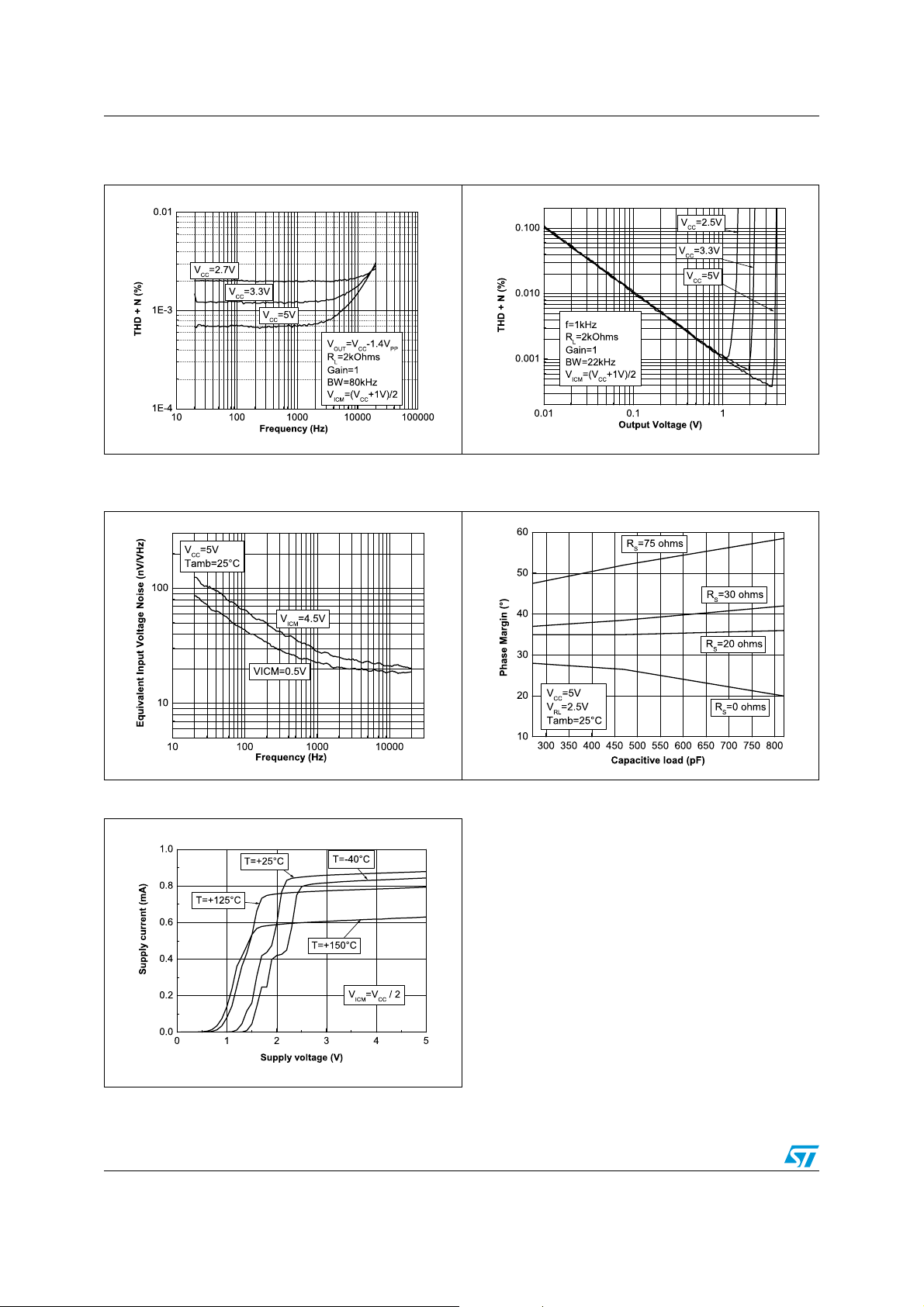
Figure 13. Distortion + noise vs. frequency Figure 14. Distortion + noise vs. output
voltage
Figure 15. Noise vs. frequency Figure 16. Phase margin vs. capacitive load
and serial resistor
Figure 17. Supply current vs. supply voltage
10/16 Doc ID 17688 Rev 1
Page 11
TSV912H, TSV912AH Application information
3 Application information
3.1 Driving resistive and capacitive loads
These products are low-voltage, low-power operational amplifiers optimized to drive rather
large resistive loads above 2 kΩ.
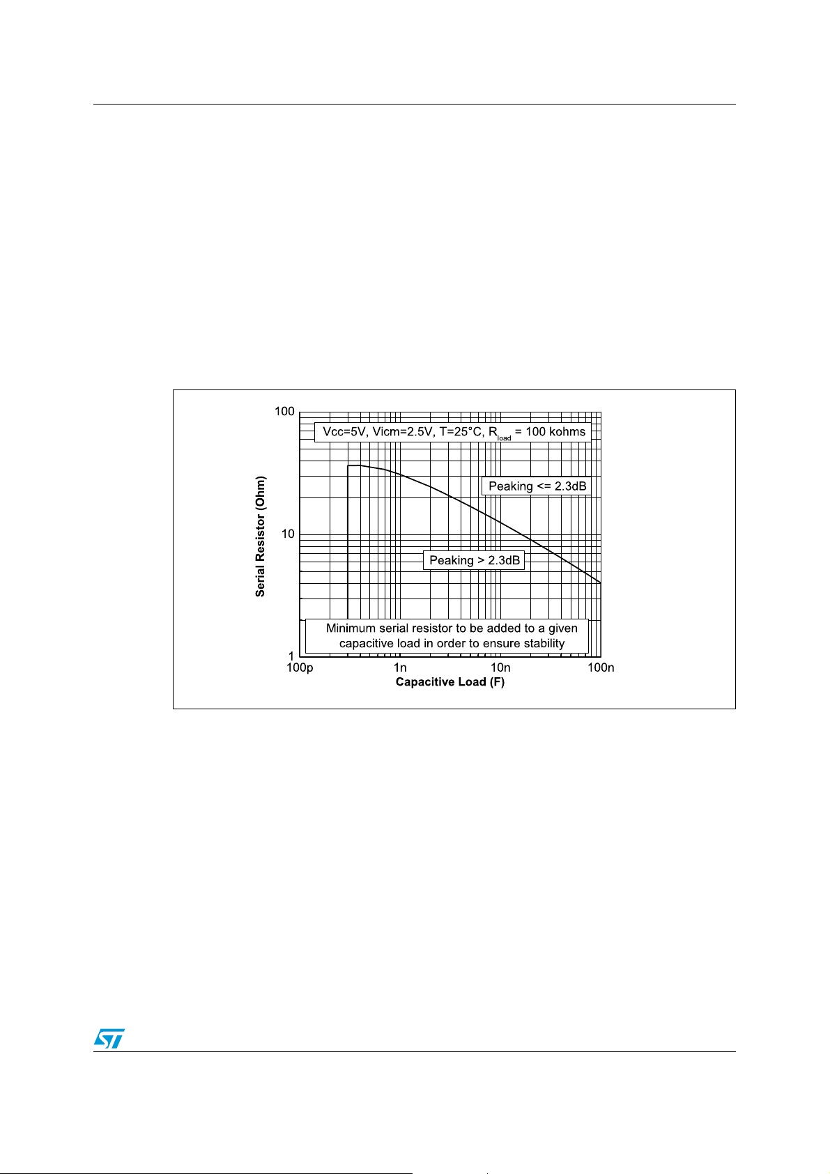
In a follower configuration, these operational amplifiers can drive capacitive loads up to
100 pF with no oscillations. When driving larger capacitive loads, adding a small in-series
resistor at the output can improve the stability of the devices (see Figure 18 for
recommended in-series resistor values). Once the in-series resistor value has been
selected, the stability of the circuit should be tested on bench and simulated with the
simulation model.
Figure 18. In-series resistor vs. capacitive load
3.2 PCB layouts
For correct operation, it is advised to add 10 nF decoupling capacitors as close as possible
to the power supply pins.
Doc ID 17688 Rev 1 11/16
Page 12

Package information TSV912H, TSV912AH
4 Package information
In order to meet environmental requirements, ST offers these devices in different grades of
ECOPACK
specifications, grade definitions and product status are available at: www.st.com.
ECOPACK
®
packages, depending on their level of environmental compliance. ECOPACK®
®
is an ST trademark.
12/16 Doc ID 17688 Rev 1
Page 13
TSV912H, TSV912AH Package information
4.1 SO-8 package information
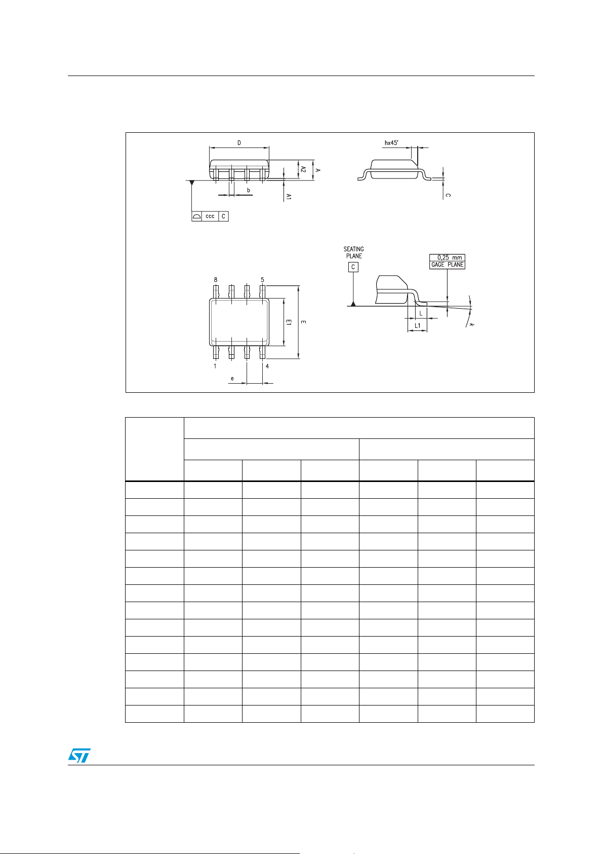
Figure 19. SO-8 package mechanical drawing
Table 6. SO-8 package mechanical data
Dimensions
Ref.
Min. Typ. Max. Min. Typ. Max.
A1.750.069
A1 0.10 0.25 0.004 0.010
A2 1.25 0.049
b 0.28 0.48 0.011 0.019
c 0.17 0.23 0.007 0.010
D 4.80 4.90 5.00 0.189 0.193 0.197
E 5.80 6.00 6.20 0.228 0.236 0.244
E1 3.80 3.90 4.00 0.150 0.154 0.157
e 1.27 0.050
h 0.25 0.50 0.010 0.020
L 0.40 1.27 0.016 0.050
L1 1.04 0.040
k 0 8° 1° 8°
ccc 0.10 0.004
Millimeters Inches
Doc ID 17688 Rev 1 13/16
Page 14
Ordering information TSV912H, TSV912AH
5 Ordering information
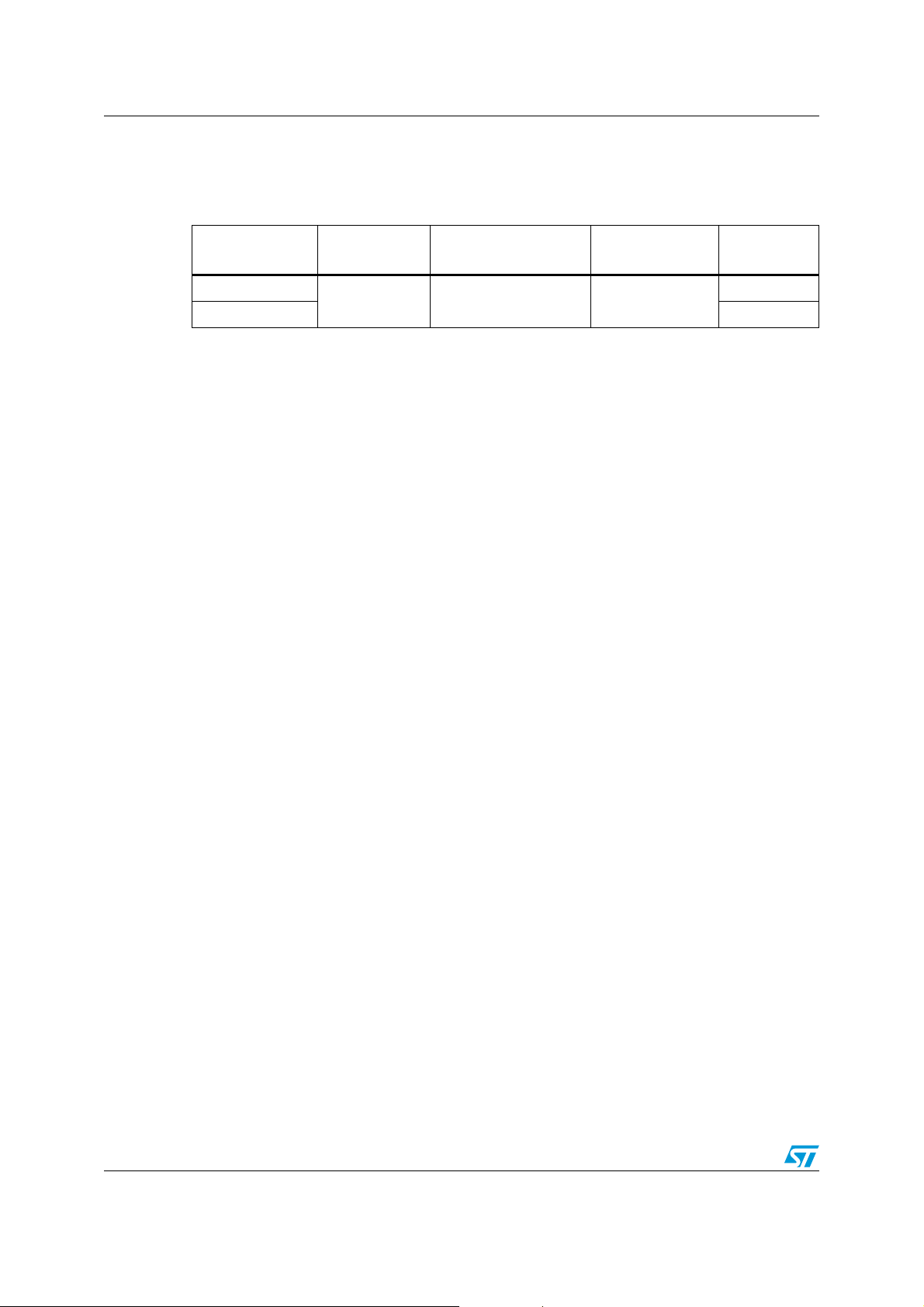
Table 7. Order codes
Order code
TSV912HYDT
(1)
TSV912AHYDT
1. Qualification and characterization according to AEC Q100 and Q003 or equivalent, advanced screening
according to AEC Q001 & Q 002 or equivalent.
2. SO8 package is Moisture Sensitivity Level 1 as per Jedec J-STD-020-C.
Temperature
range
-40°C to +150°C
(1)
Package Packing Marking
(2)
SO-8
(automotive grade level)
Tape & reel
V912HY
V912AHY
14/16 Doc ID 17688 Rev 1
Page 15
TSV912H, TSV912AH Revision history
6 Revision history
Table 8. Document revision history
Date Revision Changes
08-Jul-2010 1 Initial release.
Doc ID 17688 Rev 1 15/16
Page 16

TSV912H, TSV912AH
Please Read Carefully:
Information in this document is provided solely in connection with ST products. STMicroelectronics NV and its subsidiaries (“ST”) reserve the
right to make changes, corrections, modifications or improvements, to this document, and the products and services described herein at any
time, without notice.
All ST products are sold pursuant to ST’s terms and conditions of sale.
Purchasers are solely responsible for the choice, selection and use of the ST products and services described herein, and ST assumes no
liability whatsoever relating to the choice, selection or use of the ST products and services described herein.
No license, express or implied, by estoppel or otherwise, to any intellectual property rights is granted under this document. If any part of this
document refers to any third party products or services it shall not be deemed a license grant by ST for the use of such third party products
or services, or any intellectual property contained therein or considered as a warranty covering the use in any manner whatsoever of such
third party products or services or any intellectual property contained therein.
UNLESS OTHERWISE SET FORTH IN ST’S TERMS AND CONDITIONS OF SALE ST DISCLAIMS ANY EXPRESS OR IMPLIED
WARRANTY WITH RESPECT TO THE USE AND/OR SALE OF ST PRODUCTS INCLUDING WITHOUT LIMITATION IMPLIED
WARRANTIES OF MERCHANTABILITY, FITNESS FOR A PARTICULAR PURPOSE (AND THEIR EQUIVALENTS UNDER THE LAWS
OF ANY JURISDICTION), OR INFRINGEMENT OF ANY PATENT, COPYRIGHT OR OTHER INTELLECTUAL PROPERTY RIGHT.
UNLESS EXPRESSLY APPROVED IN WRITING BY AN AUTHORIZED ST REPRESENTATIVE, ST PRODUCTS ARE NOT
RECOMMENDED, AUTHORIZED OR WARRANTED FOR USE IN MILITARY, AIR CRAFT, SPACE, LIFE SAVING, OR LIFE SUSTAINING
APPLICATIONS, NOR IN PRODUCTS OR SYSTEMS WHERE FAILURE OR MALFUNCTION MAY RESULT IN PERSONAL INJURY,
DEATH, OR SEVERE PROPERTY OR ENVIRONMENTAL DAMAGE. ST PRODUCTS WHICH ARE NOT SPECIFIED AS "AUTOMOTIVE
GRADE" MAY ONLY BE USED IN AUTOMOTIVE APPLICATIONS AT USER’S OWN RISK.
Resale of ST products with provisions different from the statements and/or technical features set forth in this document shall immediately void
any warranty granted by ST for the ST product or service described herein and shall not create or extend in any manner whatsoever, any
liability of ST.
ST and the ST logo are trademarks or registered trademarks of ST in various countries.
Information in this document supersedes and replaces all information previously supplied.
The ST logo is a registered trademark of STMicroelectronics. All other names are the property of their respective owners.
© 2010 STMicroelectronics - All rights reserved
STMicroelectronics group of companies
Australia - Belgium - Brazil - Canada - China - Czech Republic - Finland - France - Germany - Hong Kong - India - Israel - Italy - Japan -
Malaysia - Malta - Morocco - Philippines - Singapore - Spain - Sweden - Switzerland - United Kingdom - United States of America
www.st.com
16/16 Doc ID 17688 Rev 1
 Loading...