

Page 1
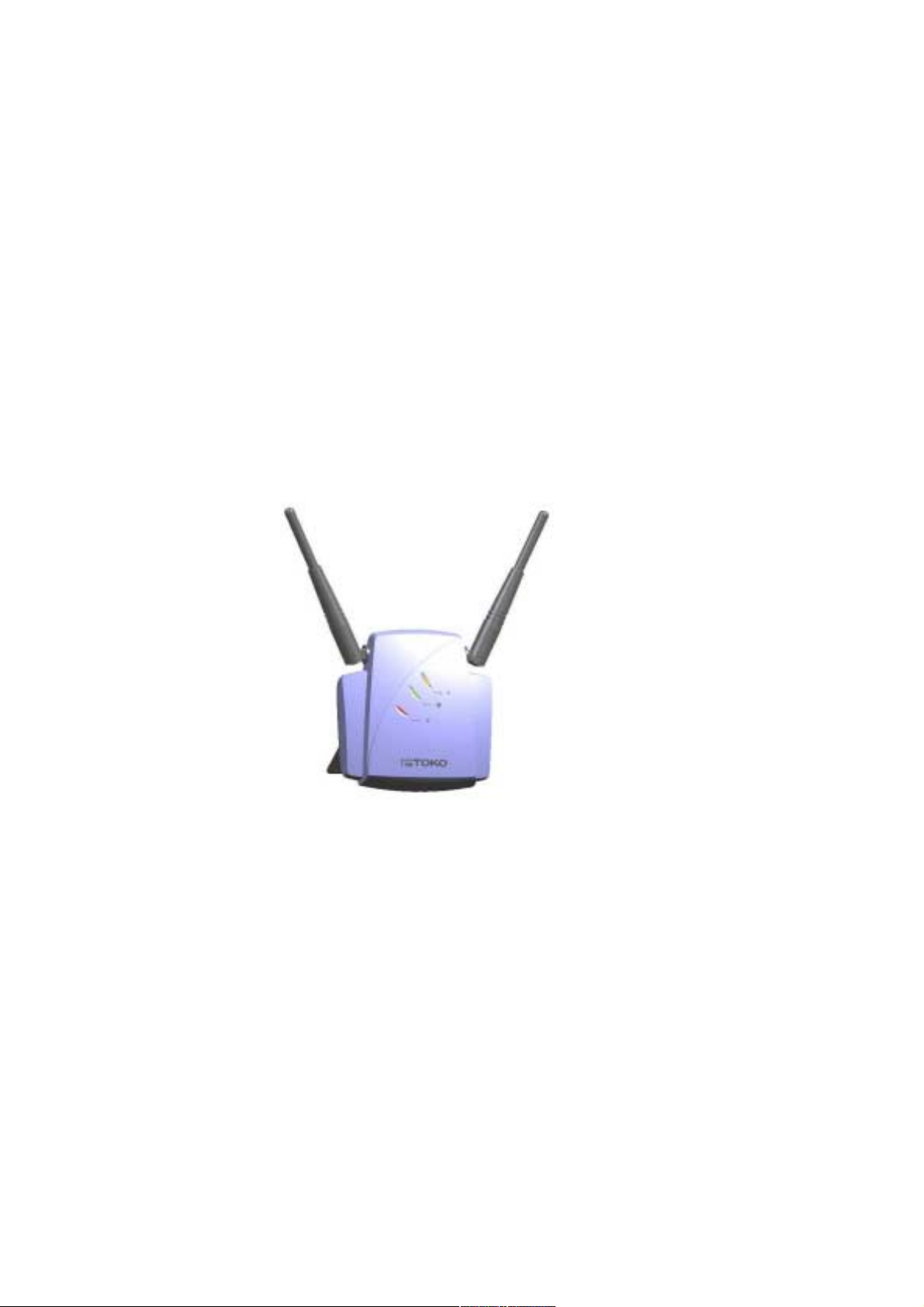
11 Mbps Wireless LAN Access Point
TMW1003UserManual
Document version: 1.0
Document number: 555004.doc
Page 2

FCC Regulation
INTERFERENCE INFORMATION: PART 15 OF FCC RULES
Some telephone equipment generates and uses radio frequency energy, which
if not properly installed, may cause interference to radio television reception.
This unit has been tested and found comply with the limits for a Class B
computing device in accordance with Part 15 of the FCC rules. These
specifications are designed to provide reasonable protection against such
interference in a residential installation. However, there is no guarantee that
interference will not occur in a particular installation.
If this equipment does cause interference to radio or television reception,
when it's in use, the user is encouraged to try to correct the interference by
one or more of the following measures:
A. Where it can be done safely, reorient the radio or TV receiving antenna.
B. To the extent possible, relocate the television, radio, or other receiver
with respect to telephone equipment.
C. If your telephone product runs on AC power, plug your product into an
AC outlet that's not on the same circuit as the one used by the radio or
television.
SAFETY INFORMATION
Your device contains a low power transmitter. When device is transmitted it
sends out radio frequency (RF) signal.
CAUTION: To maintain compliance with FCC’s RF exposure guidelines, this
equipment should be installed and operated with minimum distance 20cm
between the radiator and your body. Use on the supplied antenna.
Unauthorized antenna, modification, or attachments could damage the
transmitter and may violate FCC regulations.
2
version 1.0
Page 3

Contents
Contents
1 Getting started . . . . . . . . . . . . . . . . . . . . . . . . . . . . . . . . . . .7
1.1 Introduction . . . . . . . . . . . . . . . . . . . . . . . . . . . . . . . . . . . . . . . . . . . . . . 7
1.2 Contents of this manual . . . . . . . . . . . . . . . . . . . . . . . . . . . . . . . . . . . . . 7
1.3 Wireless LAN basics and advantages . . . . . . . . . . . . . . . . . . . . . . . . . . 8
1.4 Adding Access Points to your (network) environment . . . . . . . . . . . . . . 8
1.4.1 Creating a wireless network . . . . . . . . . . . . . . . . . . . . . . . . . . . . . . . . . . 9
1.4.2 Extending a wired network with one or more Access Points . . . . . . . . 10
1.4.3 Connecting an Access Point directly to a computer . . . . . . . . . . . . . . . 11
2 Installing the Access Point . . . . . . . . . . . . . . . . . . . . . . . .13
2.1 Introduction . . . . . . . . . . . . . . . . . . . . . . . . . . . . . . . . . . . . . . . . . . . . . 13
2.2 Access Point environment . . . . . . . . . . . . . . . . . . . . . . . . . . . . . . . . . . 13
2.3 Physical installation of the Access Point . . . . . . . . . . . . . . . . . . . . . . . 13
2.4 Desktop installation . . . . . . . . . . . . . . . . . . . . . . . . . . . . . . . . . . . . . . . 14
2.5 Wall mount installation . . . . . . . . . . . . . . . . . . . . . . . . . . . . . . . . . . . . . 15
2.6 Connecting the Access Point . . . . . . . . . . . . . . . . . . . . . . . . . . . . . . . . 16
2.6.1 Power adapter . . . . . . . . . . . . . . . . . . . . . . . . . . . . . . . . . . . . . . . . . . . 17
2.6.2 UTP port . . . . . . . . . . . . . . . . . . . . . . . . . . . . . . . . . . . . . . . . . . . . . . . . 17
2.7 LEDs . . . . . . . . . . . . . . . . . . . . . . . . . . . . . . . . . . . . . . . . . . . . . . . . . . 18
2.8 Unlocking the Access Point . . . . . . . . . . . . . . . . . . . . . . . . . . . . . . . . . 18
2.8.1 Unlocking the Access Point to reconfigure . . . . . . . . . . . . . . . . . . . . . . 18
2.8.2 Resetting to the default factory setting . . . . . . . . . . . . . . . . . . . . . . . . . 19
3 Configuring the Access Point . . . . . . . . . . . . . . . . . . . . .21
3.1 Introduction . . . . . . . . . . . . . . . . . . . . . . . . . . . . . . . . . . . . . . . . . . . . . 21
3.2 When to configure the Access Point . . . . . . . . . . . . . . . . . . . . . . . . . . 21
3.3 Starting the Web Interface . . . . . . . . . . . . . . . . . . . . . . . . . . . . . . . . . . 21
555004.doc
3
Page 4

Contents
3.4 Using KickStart . . . . . . . . . . . . . . . . . . . . . . . . . . . . . . . . . . . . . . . . . . .22
3.4.1 Installing KickStart . . . . . . . . . . . . . . . . . . . . . . . . . . . . . . . . . . . . . . . . .22
3.4.2 Launch KickStart . . . . . . . . . . . . . . . . . . . . . . . . . . . . . . . . . . . . . . . . . .22
3.4.3 Select wireless ethernet device . . . . . . . . . . . . . . . . . . . . . . . . . . . . . . .22
3.4.4 Device data . . . . . . . . . . . . . . . . . . . . . . . . . . . . . . . . . . . . . . . . . . . . . .23
3.4.5 Change IP settings . . . . . . . . . . . . . . . . . . . . . . . . . . . . . . . . . . . . . . . .23
3.4.6 Static IP settings . . . . . . . . . . . . . . . . . . . . . . . . . . . . . . . . . . . . . . . . . .24
3.4.7 Set Gateway address . . . . . . . . . . . . . . . . . . . . . . . . . . . . . . . . . . . . . .24
3.4.8 Changing IP settings . . . . . . . . . . . . . . . . . . . . . . . . . . . . . . . . . . . . . . .24
3.4.9 Ready to start the Web Interface . . . . . . . . . . . . . . . . . . . . . . . . . . . . . .25
3.4.10 Web Interface is launched . . . . . . . . . . . . . . . . . . . . . . . . . . . . . . . . . . .25
3.5 Launching the Web Interface manually . . . . . . . . . . . . . . . . . . . . . . . . .25
3.6 Contents of the Web Interface . . . . . . . . . . . . . . . . . . . . . . . . . . . . . . . .26
3.6.1 Settings Summary . . . . . . . . . . . . . . . . . . . . . . . . . . . . . . . . . . . . . . . . .26
3.6.2 Wireless Settings . . . . . . . . . . . . . . . . . . . . . . . . . . . . . . . . . . . . . . . . . .27
3.6.3 Security against unauthorized network access . . . . . . . . . . . . . . . . . . .27
3.6.4 To add a client to the exception list . . . . . . . . . . . . . . . . . . . . . . . . . . . .28
3.6.5 To delete a client from the exception list . . . . . . . . . . . . . . . . . . . . . . . .29
3.6.6 Security against eavesdropping . . . . . . . . . . . . . . . . . . . . . . . . . . . . . .29
3.6.7 Change WEP settings . . . . . . . . . . . . . . . . . . . . . . . . . . . . . . . . . . . . . .29
3.6.8 Security against unauthorized configuration . . . . . . . . . . . . . . . . . . . . .30
3.6.9 Identity . . . . . . . . . . . . . . . . . . . . . . . . . . . . . . . . . . . . . . . . . . . . . . . . . .31
3.6.10 IP Settings . . . . . . . . . . . . . . . . . . . . . . . . . . . . . . . . . . . . . . . . . . . . . . .31
4 Troubleshooting . . . . . . . . . . . . . . . . . . . . . . . . . . . . . . . .33
4.1 If KickStart does not find the Access Point you are looking for . . . . . . .33
4.2 Browser starts but window stays empty . . . . . . . . . . . . . . . . . . . . . . . .34
5 Technical specifications 11 Mbps WLAN Access Point 35
5.1 General Specifications . . . . . . . . . . . . . . . . . . . . . . . . . . . . . . . . . . . . .35
5.2 Radio specifications . . . . . . . . . . . . . . . . . . . . . . . . . . . . . . . . . . . . . . .36
5.3 Security specifications . . . . . . . . . . . . . . . . . . . . . . . . . . . . . . . . . . . . .36
5.4 Other specifications . . . . . . . . . . . . . . . . . . . . . . . . . . . . . . . . . . . . . . . .36
6 Regulatory notes and statements . . . . . . . . . . . . . . . . . .39
6.1 Wireless LAN, Health and Authorization for use . . . . . . . . . . . . . . . . . .39
6.2 Regulatory Information/disclaimers . . . . . . . . . . . . . . . . . . . . . . . . . . . .39
6.3 USA-FCC (Federal Communications Commission) statement . . . . . . .39
6.4 FCC Radio Frequency Exposure statement . . . . . . . . . . . . . . . . . . . . .40
6.5 FCC Interference Statement . . . . . . . . . . . . . . . . . . . . . . . . . . . . . . . . .40
6.6 Export restrictions . . . . . . . . . . . . . . . . . . . . . . . . . . . . . . . . . . . . . . . . .40
6.7 Europe - EU R&TTE Declaration of Conformity . . . . . . . . . . . . . . . . . .41
6.8 Restricted Wireless LAN device use in EU . . . . . . . . . . . . . . . . . . . . . .42
4
version 1.0
Page 5

Contents
A TCP and IP settings . . . . . . . . . . . . . . . . . . . . . . . . . . . . . .45
A.1 Introduction . . . . . . . . . . . . . . . . . . . . . . . . . . . . . . . . . . . . . . . . . . . . . 45
A.2 How do computers communicate in a network . . . . . . . . . . . . . . . . . . 45
A.2.1 IP address . . . . . . . . . . . . . . . . . . . . . . . . . . . . . . . . . . . . . . . . . . . . . . 46
A.2.2 Subnet mask . . . . . . . . . . . . . . . . . . . . . . . . . . . . . . . . . . . . . . . . . . . . 46
A.2.3 IP address range . . . . . . . . . . . . . . . . . . . . . . . . . . . . . . . . . . . . . . . . . 47
A.2.4 Reserved addresses . . . . . . . . . . . . . . . . . . . . . . . . . . . . . . . . . . . . . . 47
A.2.5 Gateway . . . . . . . . . . . . . . . . . . . . . . . . . . . . . . . . . . . . . . . . . . . . . . . . 47
A.2.6 MAC address . . . . . . . . . . . . . . . . . . . . . . . . . . . . . . . . . . . . . . . . . . . . 48
A.3 IP configuration . . . . . . . . . . . . . . . . . . . . . . . . . . . . . . . . . . . . . . . . . . 48
A.3.1 DHCP . . . . . . . . . . . . . . . . . . . . . . . . . . . . . . . . . . . . . . . . . . . . . . . . . . 48
A.3.2 Auto IP . . . . . . . . . . . . . . . . . . . . . . . . . . . . . . . . . . . . . . . . . . . . . . . . . 48
A.4 Setting up a home network and connecting it to the internet . . . . . . . . 49
B Wireless LAN . . . . . . . . . . . . . . . . . . . . . . . . . . . . . . . . . . .51
B.1 Introduction . . . . . . . . . . . . . . . . . . . . . . . . . . . . . . . . . . . . . . . . . . . . . 51
B.2 Wireless LAN . . . . . . . . . . . . . . . . . . . . . . . . . . . . . . . . . . . . . . . . . . . . 51
B.3 The Access Point . . . . . . . . . . . . . . . . . . . . . . . . . . . . . . . . . . . . . . . . . 52
B.4 Service Set ID (SSID) . . . . . . . . . . . . . . . . . . . . . . . . . . . . . . . . . . . . . 52
B.5 Physics of an Access Point . . . . . . . . . . . . . . . . . . . . . . . . . . . . . . . . . 52
B.5.1 Range . . . . . . . . . . . . . . . . . . . . . . . . . . . . . . . . . . . . . . . . . . . . . . . . . . 52
B.5.2 Data rates . . . . . . . . . . . . . . . . . . . . . . . . . . . . . . . . . . . . . . . . . . . . . . . 52
B.5.3 Regulatory Domain . . . . . . . . . . . . . . . . . . . . . . . . . . . . . . . . . . . . . . . 53
B.5.4 Radio Channels . . . . . . . . . . . . . . . . . . . . . . . . . . . . . . . . . . . . . . . . . . 53
B.6 Security . . . . . . . . . . . . . . . . . . . . . . . . . . . . . . . . . . . . . . . . . . . . . . . . 53
B.6.1 WEP . . . . . . . . . . . . . . . . . . . . . . . . . . . . . . . . . . . . . . . . . . . . . . . . . . . 54
555004.doc
5
Page 6

Contents
6
version 1.0
Page 7
1 Getting started
1.1 Introduction
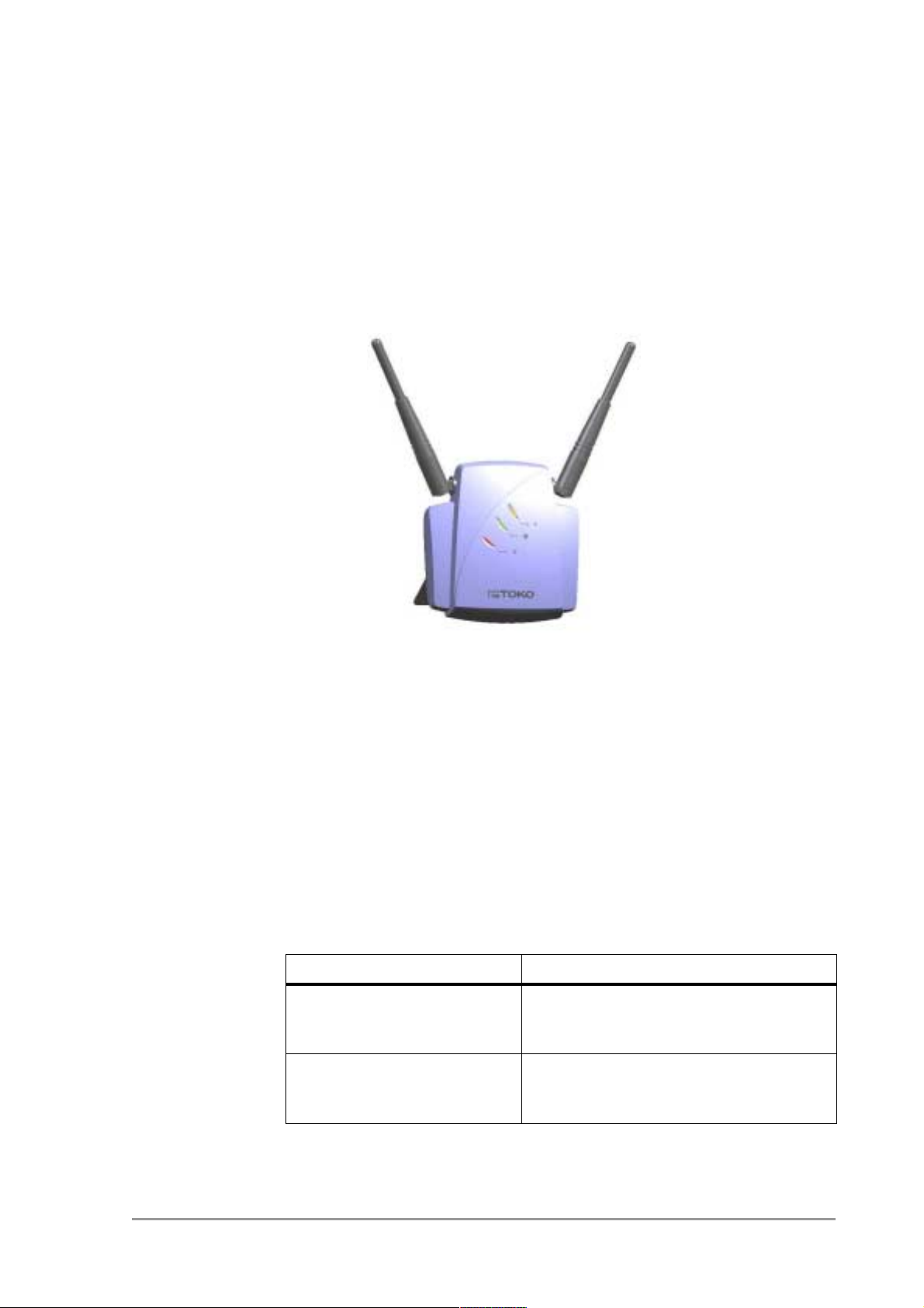
Thank you for purchasing your 11 Mbps WLAN Access Point.
Figure 1-1 11 Mbps WLAN Access Point
The package you have received contains the following items:
• user manual,
• 11 Mbps WLAN Access Point,
• power adapter,
• CD containing configuration software and this manual.
1.2 Contents of this manual
Table 1-1 gives an overview of the contents of this manual.
Table 1-1 Contents of this manual
Chapter When to read:
This chapter (“Getting
started”)
Chapter 2: ‘Installing the
Access Point’ on page 13
Read this chapter on how to implement
a Wireless LAN in your (network)
environment.
Read this for information on how to
install and connect Access Point to
your (network) environment.
555004.doc
7
Page 8

Getting started
Wireless LAN basics and advantages
Table 1-1 Contents of this manual
Chapter When to read:
Chapter 3: ‘Configuring the
Access Point’ on page 21
Chapter
4: ‘Troubleshooting’ on page
33
Chapter 5: ‘Technical
specifications 11 Mbps
WLAN Access
Point’ on page 35
Appendix A: ‘TCP and IP
settings’ on page 45
Appendix B: ‘Wireless
LAN’ on page 51
Read this chapter when you want to
adjust the settings of an Access Point.
This chapter will also explain when to
adjust the settings.
Read this chapter when the Access
Point does not function.
This chapter contains the technical
specifications of the Access Point.
This appendix contains background
information on TCP/IP settings and
other networking terminology.
This appendix contains some
background information on wireless
LANs.
Read this appendix when you are not
familiar with radiographic terminology
and wireless networking.
1.3 Wireless LAN basics and advantages
A wireless LAN connects computers to each other using radio
technology. This offers you the freedom to move around the area and
work anywhere within radiographic reach of an Access Point.
The Access Points can be connected to a wired network. This allows
wireless clients to communicate with computers on the wired network.
The technology is an extension to the existing Ethernet networking
standard, so you can connect the Access Point to an existing Ethernet
network (for more detailed information on the standards supported, see
chapter 5: ‘Technical specifications 11 Mbps WLAN Access
Point’ on page 35).
1.4 Adding Access Points to your (network) environment
Where to place and how to connect an Access Point depends entirely on
your specific (network) environment. In this section some guidelines on
how to add Access Points to your environment are given.
8
version 1.0
Page 9
Getting started Adding Access Points to your (network) environment
An Access Point can be used to
• create a wireless network (see section 1.4.1),
• extend an existing wired network (see section 1.4.2),
• connect to a single computer (see section 1.4.3).
1.4.1 Creating a wireless network
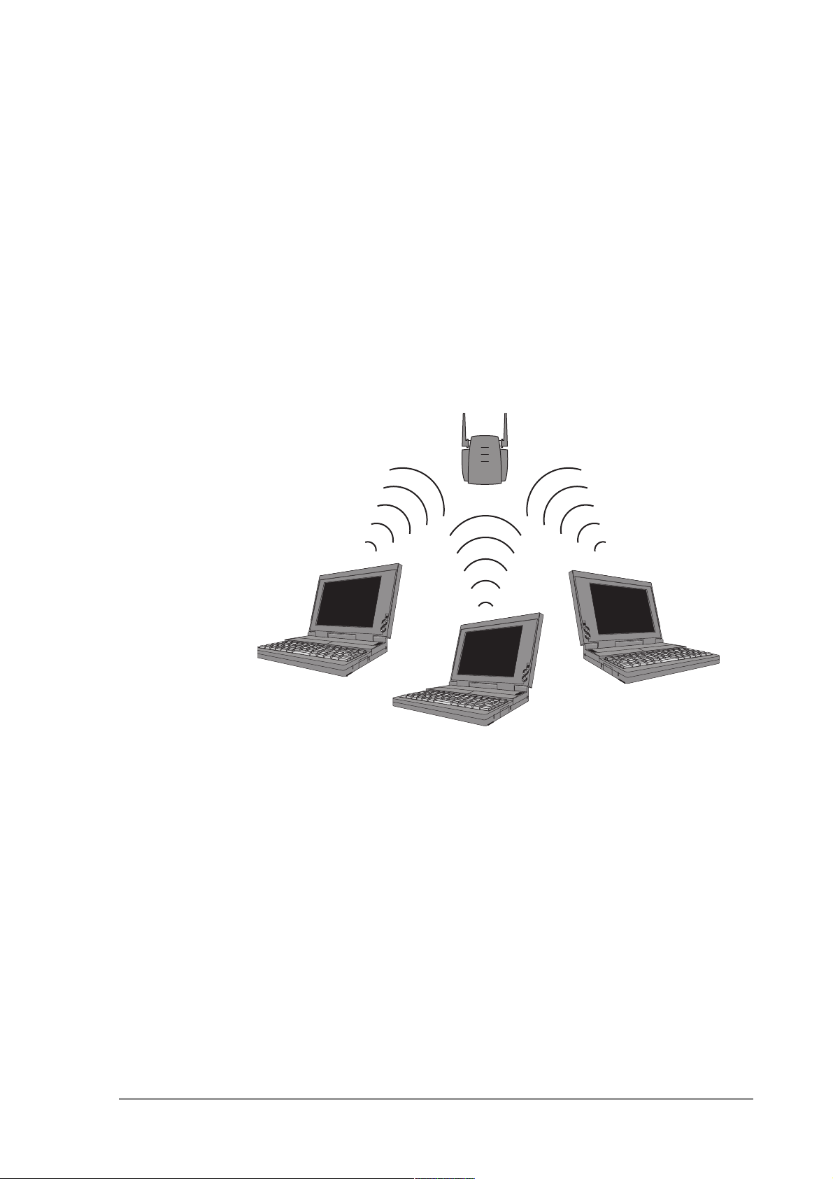
You can use an Access Point to set up a wireless network, see
Figure 1-2.
555004.doc
Figure 1-2 Wireless network
When you install a new wireless network, follow these steps:
1. Prepare one client (install wireless network card and software).
2. Select the IP settings of this client.
3. Install the Access Point.
You can now use the wireless network.
4. Optionally, configure the Access Point from the already configured
client using KickStart and the Web Interface (see chapter
3: ‘Configuring the Access Point’ on page 21).
5. Install other clients if this is applicable to your situation.
9
Page 10
Getting started
Adding Access Points to your (network) environment
1.4.2 Extending a wired network with one or more Access Points
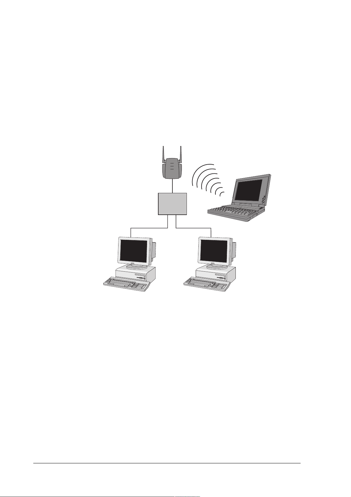
When your Access Point is an extension to a wired network, it is
recommended that you make sure that the wired network is completely
functional to exclude existing problems.
See Figure 1-3.
hub
wired network
Figure 1-3 Adding an Access Point to a wired network
Follow these steps:
1. Install the Access Point and connect it to your wired network.
You can now use the wireless network.
2. Optionally, configure the Access Point from an existing computer in
the network using KickStart and the Web Interface (see chapter
3: ‘Configuring the Access Point’ on page 21).
3. Install the wireless client(s).
10
version 1.0
Page 11
Getting started Adding Access Points to your (network) environment
1.4.3 Connecting an Access Point directly to a computer
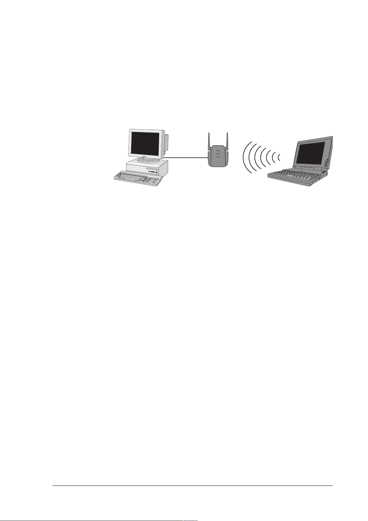
You can also connect an Access Point directly to your computer. See
Figure 1-4.
Figure 1-4 Connecting an Access Point directly to a computer
n
Follow these steps:
1. Install a network card in the computer you want to connect the
Access Point to.
2. Select the IP settings of this client.
3. Install the Access Point.
Note: for this connection you need to use a crosswired cable.
You can now use the wireless network.
4. Optionally, configure the Access Point from your computer using
KickStart and the Web Interface (see chapter 3: ‘Configuring the
Access Point’ on page 21).
5. Install the wireless client(s).
555004.doc
11
Page 12

Getting started
Adding Access Points to your (network) environment
12
version 1.0
Page 13

Installing the Access Point Introduction
2 Installing the Access
Point
2.1 Introduction
This chapter describes the physical installation of an Access Point.
Table 2-1 Overview of this chapter.
Section Describes
2.2 Considerations about the physical environment of
an Access Point.
2.3, 2.4, 2.5 How to install an Access Point.
2.6 How to connect the Access Point.
2.7 Explanation of the LEDs.
2.8 How to unlock/reset the Access Point.
2.2 Access Point environment
When you install an Access Point, you must consider the following items:
• Connection to the electricity net.
• Connection to the network.
• Environment of device (heat/humidity): see chapter 5: ‘Technical
specifications 11 Mbps WLAN Access Point’ on page 35.
• Range of device: see chapter 5: ‘Technical specifications 11 Mbps
WLAN Access Point’ on page 35.
2.3 Physical installation of the Access Point
n
555004.doc
For best performance, install the antennas on the Access Point in a
vertical position.
13
Page 14
Installing the Access Point
Desktop installation
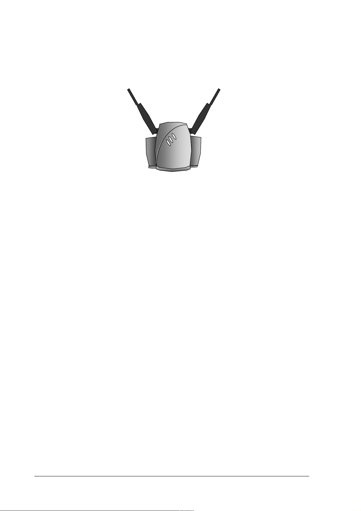
Figure 2-1 The Access Point
The Access Point can be installed in 2 different ways:
• on a desktop,
• mounted to a wall.
The package contains screws and plugs to fasten the Access Point to a
wall.
2.4 Desktop installation
See chapter 5: ‘Technical specifications 11 Mbps WLAN Access
Point’ on page 35 for regulations on the required free space around the
Access Point.
Determine where you want to place the Access Point. Make sure you
have a clear area on a desktop.
14
version 1.0
Page 15
Installing the Access Point Wall mount installation
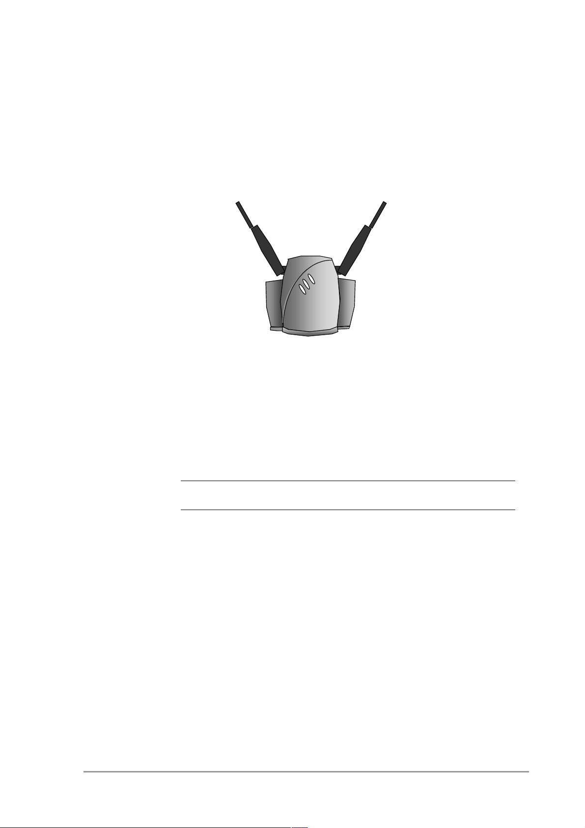
You can simply place the Access Point on a desktop and point the
antennas upwards (see Figure 2-2: ‘Access Point for desktop
use’ on page 15).
Figure 2-2 Access Point for desktop use
2.5 Wall mount installation
See chapter 5: ‘Technical specifications 11 Mbps WLAN Access
Point’ on page 35 for regulations on the required free space around the
Access Point.
wwww
Before you start drilling holes into a wall, make sure that part of the
wall is clear of electricity and water pipes.
555004.doc
15
Page 16
Installing the Access Point
Connecting the Access Point
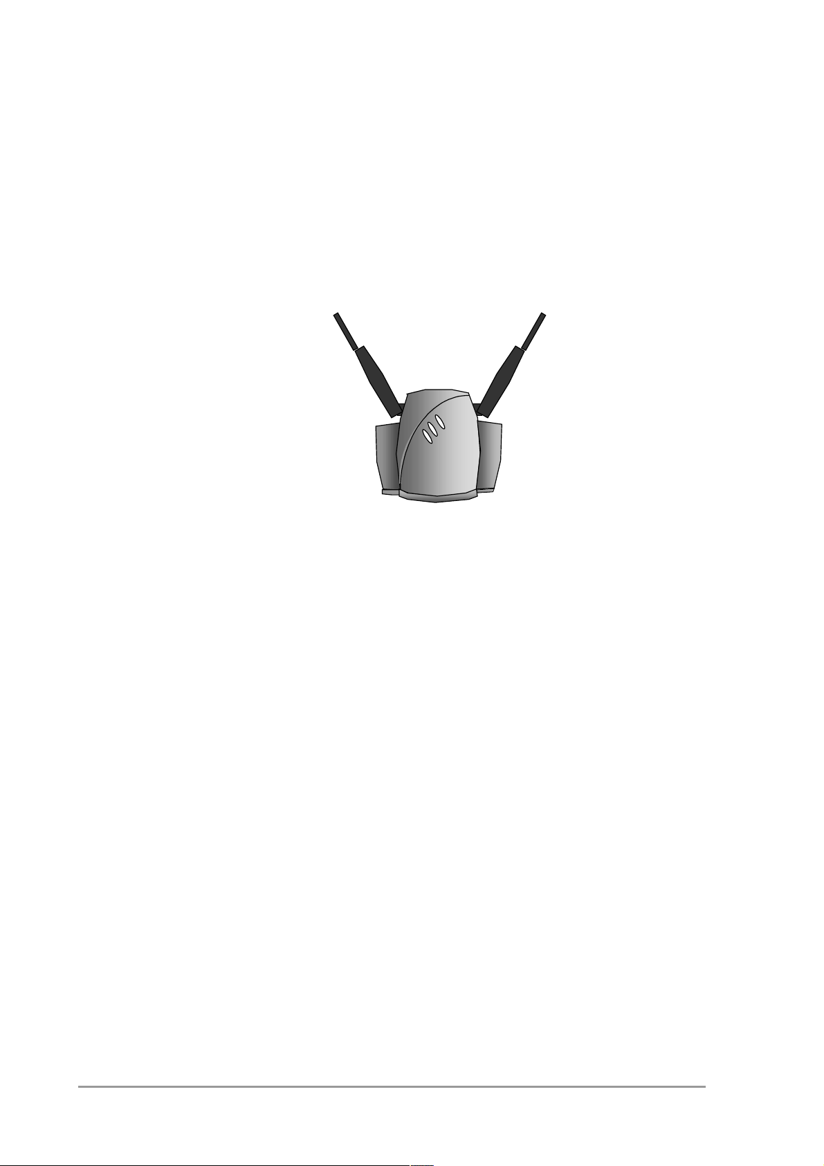
The wall mount package contains two screws and plugs to fasten the
socket to the wall (see Figure 2-3: ‘Backside of the Access
Point’ on page 16.
Figure 2-3 Backside of the Access Point
Step by step wall mount installation:
1. Determine the position of the screws. The screws must be 83 mm
apart to fit the keyholes at the back of the Access Point.
2. Drill holes in the wall at the location of the dots.
3. Insert the plugs into the holes.
4. Fasten the screws into the plugs, and leave about 3 mm of space
between wall and screw head.
5. Attach the Access Point to the screws.
2.6 Connecting the Access Point
Your Access Point is now ready to be connected to the electricity net and
to your network. See 1.4: ‘Adding Access Points to your (network)
environment’ on page 8 on how to add Access Points to your network or
environment.
16
version 1.0
Page 17
Installing the Access Point Connecting the Access Point
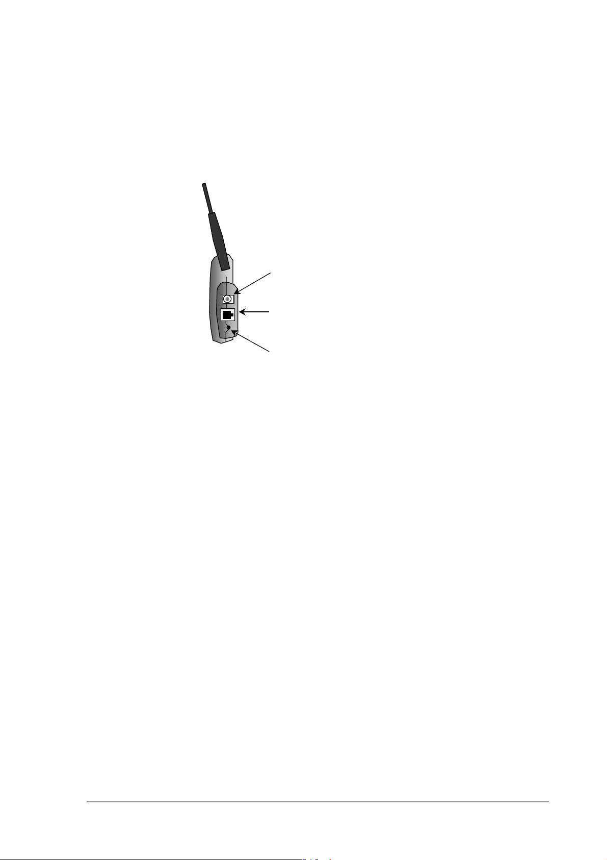
You can find the power input and the UTP port on the right hand side of
the Access Point.
Power
UTP port
Figure 2-4 Connecting the Access Point
2.6.1 Power adapter
The Access Point package contains a power adapter. Attach it to the
Access Point. and then check the power LED (see section
2.7: ‘LEDs’ on page 18) to see if you are connected properly.
2.6.2 UTP port
The UTP port can be found next to the power connector on the Access
Point.
For a wired connection (see section 1.4.2: ‘Extending a wired network
with one or more Access Points’ on page 10 and section
1.4.3: ‘Connecting an Access Point directly to a computer’ on page 11),
attach the UTP Ethernet cable to the Access Point and connect the
cable on the other end to either a hub in the network, or a computer.
Reset
555004.doc
If you want to connect to an Access Point via a wired connection, it must
be connected correctly:
• if the Access Point is connected to a hub or switch, a ‘normal’ (not a
crosswired) cable must be used,
• if the Access Point is connected directly to a computer, a crosswired
cable must be used.
17
Page 18
Installing the Access Point
LEDs
2.7 LEDs
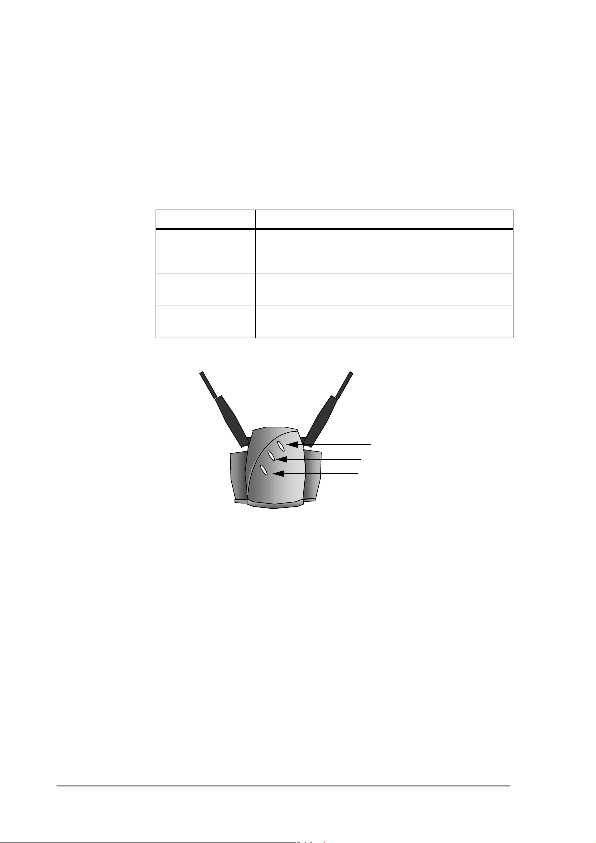
The Access Point has three LEDs.
Table 2-2 LEDs
LED Function
Power The power LED burns when the Access Point is
connected to the electricity net. See also section
2.6: ‘Connecting the Access Point’ on page 16
Radio signal The radio LED blinks when the Access Point is
active.
Network
connection
Figure 2-5: ‘Access Point LEDs’ on page 18 shows the LEDs.
Figure 2-5 Access Point LEDs
2.8 Unlocking the Access Point
The unlock/reset button is found underneath to the power connector and
UTP connector. It is a small hole for which you need the end of a
paperclip.
The network LED burns when the Access Point is
connected to a wired network.
Power LED
Radio LED
Network LED
18
You can unlock the Access Point in order to reconfigure it, or reset it to
the default factory settings.
2.8.1 Unlocking the Access Point to reconfigure
From the Web Interface you can lock the Access Point, prohibiting
configuration changes to it (see section 3.6.8: ‘Security against
unauthorized configuration’ on page 30).
version 1.0
Page 19

Installing the Access Point Unlocking the Access Point
To unlock the Access Point so that the configuration changes are
allowed again:
1. Insert one end of a paperclip briefly in the hole of the reset button.
The Access Point lock is unlocked. All settings, including the IP
settings, are retained.
2. You can now use the Web Interface to manage the Access Point
again.
2.8.2 Resetting to the default factory setting
If you press the reset button longer, more than 5 seconds, the Access
Point will be reset to the default factory settings:
1. Insert one end of a paperclip into the hole for the reset button and
keep it pressed down.
The radio LED will first burn constantly.
2. Release the reset button when the LED has stopped burning.
All settings are deleted.
3. Use KickStart to install new IP settings.
(If you have a DHCP server the IP settings will probably remain the
same.)
4. You can now use the Web Interface to manage the Access Point
again.
555004.doc
19
Page 20

Installing the Access Point
Unlocking the Access Point
20
version 1.0
Page 21

3 Configuring the Access
Point
3.1 Introduction
The Access Point is a ready to use device. It is delivered with default
settings which allow you to have access to it without configuring it. When
you do configure the Access Point, you can change the settings with
respect to security, radio channels, etc.
Whether you need to configure the Access Point or not, depends entirely
on how you apply the Access Point to your environment. Section
3.2: ‘When to configure the Access Point’ on page 21 discusses the
consequences of configuring the Access Point or not.
You configure the Access Point via Web pages that are built into the
Access Point. These are accessible via any Web browser. The KickStart
application helps you access this Web Interface.
Table 3-1 describes the contents of this chapter:
Table 3-1 Overview of this chapter
Section Description
2 When to configure the Access Point
3 Starting the Web Interface
4 Launching the Web Interface manually
5 Contents of the Web Interface
3.2 When to configure the Access Point
Configuring the Access Point means installing settings with respect to
the use of radio channels, security, identification, etc. You only need to
configure the Access Point when you want to change these settings.
n
3.3 Starting the Web Interface
Not configuring your Access Point will make your network accessible to
anyone.
555004.doc
The first time you want to access the Web Interface, you need to use
KickStart to find it. For subsequent access, you can go to the Web
Interface directly (see section 3.5: ‘Launching the Web Interface
manually’ on page 25) and you don’t need KickStart.
Tip: you can bookmark the web address for the Web Interface for even
easier access.
21
Page 22

Configuring the Access Point
Using KickStart
You also need to use KickStart after you have reset the Access Point to
factory defaults (see section 2.8.2: ‘Resetting to the default factory
setting’ on page 19).
3.4 Using KickStart
KickStart helps you start the Web Interface: it finds all Access Points in
your network and it opens the Web Interface of an Access Point.
If your network uses DHCP or Auto IP to assign IP addresses, KickStart
retrieves the address assigned to the Access Point.
If your network uses static IP addresses, KickStart allows you to change
the IP address settings for an Access Point.
3.4.1 Installing KickStart
You can install KickStart on any PC in the network to which the Access
Point will be connected. Follow the instructions of the installation wizard.
3.4.2 Launch KickStart
Launch KickStart via the
When you click
range, whether they have been configured properly or not.
3.4.3 Select wireless ethernet device
In the ‘Select wireless ethernet device’ dialog, select the Access Point
you want to configure from the list. Once you have selected an Access
Point, click
If the Access Point you are looking for does not appear in the list, click
Rescan
this to find Access Points that have just been switched on or reset.
These devices may take up to a minute to find an IP address, and they
won’t appear in the list until then.
If the device that you want to manage is not in the list and is not found
after clicking the
find the Access Point you are looking for’ on page 33.
. KickStart will search for Access Points again. For example, use
Next
Next
to continue.
Rescan
Start
, KickStart will search for all Access Points within
button, go to section 4.1: ‘If KickStart does not
menu. The application starts up.
22
Section 3.4.4: ‘Device data’ on page 23 explains the data in the ‘Select
Wireless Ethernet Device’ dialog.
version 1.0
Page 23

Configuring the Access Point Using KickStart
3.4.4 Device data
The columns in the ‘Select Wireless Ethernet Device ‘ dialog contain the
properties of all detected wireless devices. Table 3-2 explains the device
data in these columns (see also Appendix A: ‘TCP and IP
settings’ on page 45):
Table 3-2 Description of the device data in the ‘Select Wireless Device
Ethernet’ dialog
Column Description
Name The name of the Access Point. This is identical to
the SSID.
MAC address Every Ethernet device has a unique address that
is permanently linked to that device. It cannot be
changed.
See section A.2.6: ‘MAC address’ on page 48.
IP address In order to access a TCP/IP network, a device
must have an IP address in addition to its MAC
address.
See Appendix A: ‘TCP and IP
settings’ on page 45.
SSID The SSID is also known as Service Set ID. This is
the name of your wireless network.
See section B.4: ‘Service Set ID
(SSID)’ on page 52.
Location The location of the Access Point.
See section 3.6.9: ‘Identity’ on page 31 on how to
edit this field.
Contact The name of the contact person for the Access
Point.
See section 3.6.9: ‘Identity’ on page 31 on how to
edit this field.
3.4.5 Change IP settings
555004.doc
In the ‘Change IP Settings’ dialog you can select to either use dynamic
or static IP settings. (see appendix A: ‘TCP and IP settings’ on page 45).
Select Dynamic IP settings when you install the Access Point in a
network with a DHCP server or Auto IP.
23
Page 24

Configuring the Access Point
Using KickStart
Select Static IP settings when you want to configure the IP settings
manually.
Click on the Next button to continue to the next screen.
• If you selected the option
continue to the ‘Changing IP settings’ dialog directly, see section
3.4.8: ‘Changing IP settings’ on page 24.
• If you selected the option
continue to the ‘Set IP address of Wireless Device’ dialog, see
section 3.4.6: ‘Static IP settings’ on page 24.
3.4.6 Static IP settings
If you selected the option
Settings’ dialog, you will enter the ‘Set IP Address of Wireless Device’
dialog.
Here you can either manually insert an IP address and Subnet mask, or
you can click Suggest
Click Next to continue to the next screen. The screen “Set Gateway of
Wireless Device” appears, see section 3.4.7: ‘Set Gateway
address’ on page 24.
3.4.7 Set Gateway address
In the ‘Set Gateway of Wireless Device’ dialog you can set the Gateway
address of the wireless device. Setting a gateway address is optional.
Use dynamic IP settings
Use static IP settings
Use static IP setting
to let the system find suitable IP settings.
in the ‘Change IP
, you will
, you will
24
A gateway is used, for example, to connect your network to the internet.
to continue to the next screen, see section 3.4.8: ‘Changing
Next
Click
IP settings’ on page 24.
3.4.8 Changing IP settings
KickStart will install the proper IP settings of the device.
If it cannot install the proper IP settings, a warning is given. With the
button you can return to the Change IP settings dialog (see section
Back
3.4.5 on page 23) where you can select another method for installing the
IP settings.
If the IP settings were set successfully, the
Click
, and the ‘Ready to start’ dialog appears.
Next
button is activated.
Next
version 1.0
Page 25

Configuring the Access Point Launching the Web Interface manually
3.4.9 Ready to start the Web Interface
If you click
and open the Web Interface for the Access Point you have chosen. Then
KickStart quits.
You can now go to section 3.6: ‘Contents of the Web
Interface’ on page 26.
When you use KickStart to find an Access Point that already has correct
IP settings, KickStart will go directly from the ‘Select wireless ethernet
device’ dialog to this page. It will not allow you to change the IP address
settings. If you do want to change these, you will need to run KickStart
as follows:
1. Find the directory that contains KickStart.exe.
2. From the
3. In the Run dialog, browse to the directory that contains KickStart.exe
and select KickStart.exe.
4. Click Open. You will return to the Run dialog.
5. Edit the path: after
Example:
"C:\Program Files\KickStart\KickStart.exe /a"
Finish
in this screen, KickStart will launch a Web browser
Start
menu, select
KickStart.exe
Run
...
, append
/a
This will force KickStart to display the ‘Change IP settings’ dialog.
3.4.10 Web Interface is launched
Once the KickStart application has finished and the Access Point is
available for configuration in the network, the Web Interface application
is launched in a web browser.
You can now edit the settings for the Access Point.
3.5 Launching the Web Interface manually
When you know the IP address of an Access Point, you can manually
open the Web Interface in a web browser, just as you would any other
Web page.
1. Open a web browser.
2. Insert the web address of the Access Point on the address bar as
follows:
http://IP address of the Access Point/
Tip: you can bookmark the web address for the Web Interface for easier
access.
555004.doc
25
Page 26

Configuring the Access Point
Contents of the Web Interface
3.6 Contents of the Web Interface
With the Web Interface application, you can:
• View a number of settings for the Access Point,
• Change most of these settings.
Table 3-3 Contents of Web Interface
Page Description
Settings summary Lists the current settings for SSID, IP Address and
security (network access and eavesdropping).
Wireless settings Modify the wireless settings (radio channel,
SSID).
Security against
unauthorized
network access
Security against
eavesdropping
Security against
unauthorized
configuration
Identity Modify the identity data (location, contact
IP settings Lists the IP, subnet, and gateway addresses of the
3.6.1 Settings Summary
This page contains a summary of the settings of the Access Point.
To display the Settings Summary page, click .
You cannot change any of the settings in this page. Table 3-4 contains
the references to the pages where these settings can be changed.
Allow or deny client access to the network via this
Access Point.
Modify security settings to prevent eavesdropping
on the connection to the Access Point.
Modify the Write Community String for the Access
Point and lock management of the Access Point.
information) of the Access Point.
Access Point.
26
Table 3-4 Web Interface page: Settings Summary
Setting How to change the setting
SSID See section 3.6.2: ‘Wireless Settings’ on page 27.
IP address You cannot change the IP address from the Web
Interface. You must use KickStart to change the IP
address (see section 3.4.2: ‘Launch
KickStart’ on page 22).
version 1.0
Page 27
Configuring the Access Point Contents of the Web Interface
Table 3-4 Web Interface page: Settings Summary
Setting How to change the setting
Access Control See section 3.6.3: ‘Security against unauthorized
network access’ on page 27.
Eavesdropping
mode
3.6.2 Wireless Settings
On this page you can install items such as the identification of the device
and the radio channel.
To display the Wireless Settings page, click .
Table 3-5 contains the descriptions of the options in this page.
Table 3-5 Web Interface page: Wireless Settings
Option Description
SSID This is the Service Set ID. Only Access Points
Radio Channel This is the channel that the Access Point uses to
See section 3.6.6: ‘Security against
eavesdropping’ on page 29.
and clients that share the same SSID are able to
communicate with each other.
See section B.4: ‘Service Set ID
(SSID)’ on page 52.
transmit and receive information (see section
B.5.4: ‘Radio Channels’ on page 53).
3.6.3 Security against unauthorized network access
555004.doc
The channel that you select here is restricted to
the channels that can be used within your
Regulatory Domain.
Regulatory
Domain
To protect your network against unauthorized network access you can
create an Access Control List (ACL).
The Regulatory Domain is displayed here. Every
region or country has a regulatory body which
governs the use of radio channels (see section
B.5.3: ‘Regulatory Domain’ on page 53).
This is a factory setting and cannot be changed.
27
Page 28

Configuring the Access Point
Contents of the Web Interface
To display the Security against unauthorized network page,
click .
You can choose to allow access to all clients or deny access to all
clients, and create a list of exceptions for both options.
The changes to the Access Control List on this page are accepted when
you click on the OK button.
The first section in this page contains two access options. Table 3-6
describes these options.
Table 3-6 Web Interface page: Security against unauthorized network
access.
Options Description
n
All clients are
accepted
Deny all clients When you select this option, you deny access to
Once you have selected whether you want to allow access to all clients
or deny all clients, you can create an exception list. See section
3.6.4: ‘To add a client to the exception list’ on page 28 and section
3.6.5: ‘To delete a client from the exception list’ on page 29.
Note: the title of the exception list reads
• “denied clients” when the exceptions are applicable to the option
Allow access to all clients.
• “accepted clients” when the exceptions are applicable to the option
Deny access to all clients.
When you select this option, you allow access to
all PC Cards, except for ones that you specify in
the exception list.
This option can be useful if you do not want to
keep track of all PC Cards but you do know some
PC Cards that need to be denied access because
they were stolen.
all PC Cards except the ones you specify in the
exception list.
28
3.6.4 To add a client to the exception list
Follow these steps to add a client to the exception list (see section
3.6.3: ‘Security against unauthorized network access’ on page 27):
1. Click on the button
2. In the field
you want to allow or deny access to.
MAC Address
Add client...
, enter the MAC address of the client that
: a new dialog opens.
version 1.0
Page 29

Configuring the Access Point Contents of the Web Interface
. The client is now added to the exception list.
3. Click
3.6.5 To delete a client from the exception list
Follow these steps to delete a client from the exception list (see section
3.6.3: ‘Security against unauthorized network access’ on page 27):
OK
1. Click on the button
the exception list is displayed.
2. Select the MAC address(es) of the client(s) that you want to remove
from the list.
3. Click on the button
3.6.6 Security against eavesdropping
The Access Point provides encryption to secure the data flow from and
to the Access Point. This can be configured in the ‘Security against
eavesdropping’ page.
To display the ‘Security against eavesdropping’ page,
click .
Table 3-7 describes the options.
Table 3-7 Web Interface page: Security against eavesdropping
Option Description
Open System When you select this option, clients have access
Delete clients
. The exception list is updated.
OK
without a password. (See section
B.6: ‘Security’ on page 53.)
: a new dialog opens in which
3.6.7 Change WEP settings
555004.doc
WEP When you select this option, you activate WEP
security. (See section B.6: ‘Security’ on page 53.)
When you select this, the ‘Enter the WEP Settings’
dialog appears, see section 3.6.7: ‘Change WEP
settings’ on page 29.
When you select the
Settings’
change the settings:
1. Select the WEP mode: 40 bit or 104 bit. This is the length of the key
you’ll need to enter. For WEP 40-bit, the key is 10 characters long.
For WEP 104-bit, the key is 26 characters long. The longer the key,
link, the ‘
radio button or click the
WEP
Enter the WEP Settings
‘Change
’ dialog appears. To
29
Page 30

Configuring the Access Point
Contents of the Web Interface
the harder it is to crack the encryption.
2. Enter a password:
- WEP 40: the key must contain exactly 10 characters.
For example: 02f4e621ac
- WEP 104: the key must contain exactly 26 characters.
For example: 02f4e621ac29183ac6b4f9a3e1
n
3.6.8 Security against unauthorized configuration
Only the following alphanumeric characters are allowed in the key:
- 0 to 9,
-a to f.
.
3. Click
On this page you can install a password, the Write Community String
(WCS). When you set a WCS, you can only make changes to the
Access Point if you supply the correct WCS.
You can also lock the Access Point; when the Access Point is locked, no
one can change its configuration. You need to press a button on the
Access Point itself to unlock it. This increases security: only people who
can physically access the Access Point, will be able to change its
configuration.
To display the Security against unauthorized configuration page,
click .
1. Change Password.
OK
30
- Click on the button
which you can enter the WCS (twice).
- Click OK. The change is applied, and a dialog asking for a user
name and password appears. Leave the ‘user name’ field empty,
and in the ‘password’ field, enter the WCS you just chose.
Once you have set a WCS, anyone who opens the Web Interface will
be presented with a dialog asking for a user name and password.
Leave the ‘user name’ field empty, and in the ‘password’ field, enter
the WCS.
2. Lock Access Point.
- Click on the button
A warning appears: “Are you sure to lock the Access Point? This will
immediately prevent making configuration changes. You will still be
able to view the current settings.”
to lock the Access Point.
- Click on
OK
Change Password
Lock
Access Point.
and a window opens in
version 1.0
Page 31
Configuring the Access Point Contents of the Web Interface
No more configuration changes to the Access Point are allowed.
To unlock the Access Point: see section 2.8.1: ‘Unlocking the Access
Point to reconfigure’ on page 18.
3.6.9 Identity
This page contains the physical information on the Access Point.
To display the Identity page, click .
Table 3-8 explains the options in this web page.
Table 3-8 Web Interface page: Identity of the Access Point.
Option Description
Location This is a text field in which you can enter where
the Access Point is installed (“Room 412”).
You can put any text into this field. The text has no
influence on how the Access Point works.
Contact This is a text field in which you can enter the
name of the systems administrator responsible for
the Access Point (“[email protected]”).
You can put any text into this field. The text has no
influence on how the Access Point works.
MAC address The MAC address is displayed here.
See section A.2.6: ‘MAC address’ on page 48.
Access Point
Type
Firmware Version Here the version of the Access Point firmware is
When you have entered or changed your data:
• Click
Cancel
Information on your type of Access Point is
displayed here.
displayed.
to discard the changes.
3.6.10 IP Settings
555004.doc
• Click
To display the IP Settings page, click .
On this web page the following IP settings are displayed:
• IP Address,
• Subnet mask,
Apply
to apply the changes to the Access Point.
31
Page 32

Configuring the Access Point
Contents of the Web Interface
• Gateway.
It is not possible to change these addresses from within the Web
Interface.
If you want to change the IP settings of an Access Point that already has
proper IP settings, you need to use KickStart and change them manually
(see section 3.4: ‘Using KickStart’ on page 22).
32
version 1.0
Page 33

4 Troubleshooting
4.1 If KickStart does not find the Access Point you are looking for
Possible cause Solution
Is the Access Point powered up? Check the power LED.
Check if the Access Point is
connected.
Is the Access Point in range of the
WLAN card on your computer?
Is there a network connection? Check the network LED.
Client cannot make connection A wireless client is not (yet)
Has the proper network cable
been used?
Check the radio signal LED.
See section 5.2: ‘Radio
specifications’ on page 36 to
check for possible problems with
respect to range.
The Access Point may take up to
a minute to find an IP address it
can use if Auto IP is used to
assign an IP address.
connected to the Access Point.
Refer to the manual of the
wireless client on how to connect.
• If the Access Point is
connected to a hub, a ‘normal’
(not a crosswired) cable must
be used,
555004.doc
• If the Access Point is
connected directly to a
computer, a crosswired cable
must be used.
33
Page 34

Troubleshooting
Browser starts but window stays empty
4.2 Browser starts but window stays empty
Possible cause:
Your browser uses a proxy server to connect to the Web Interface.
Solution:
Reconfigure the proxy settings in your browser.
To do this in Internet Explorer:
1. Go to Tools -> Internet Options... -> Connections -> LAN Settings
2. Enable "Bypass Proxy Server for local address"
34
version 1.0
Page 35
5 Technical specifications
11 Mbps WLAN Access
Point
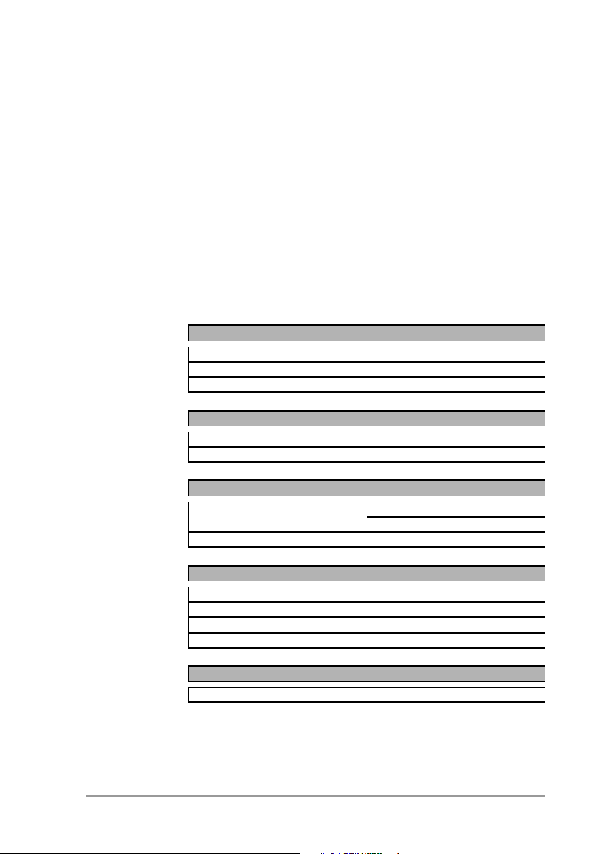
5.1 General Specifications
Standards supported
Compliant with ETS 300 328 and ETS 300 826 (CE marked)
IEEE 802.11 standard for Wireless LAN
All major networking standards (including TCP/IP, IPX)
Environmental specifications
Operating temperature (ambient) 0°C to 40°C (32°F to 104°F)
Humidity 95%
Power specifications
DC power supply In 110-230 VAC 50 Hz 150 mA
Out 5 VDC 1 A
11 Mbps WLAN Access Point In 5 VDC 1 A
Supported bit rates
11 Mbps
5.5 Mbps
2 Mbps (IEEE 802.11 DSSS compliant devices, using ASBF™ )
1 Mbps (IEEE 802.11 DSSS compliant devices, using ASBF™ )
555004.doc
Connectivity to wired networks
Connects to any 10BaseT or 100Base-T Ethernet network
35
Page 36
Technical specifications 11 Mbps WLAN Access
Point
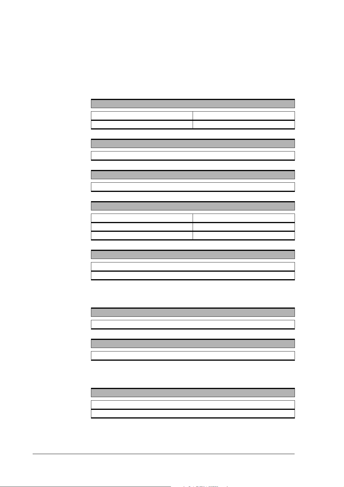
Radio specifications
5.2 Radio specifications
Range
Per cell indoors approx. 50 meters (150 ft.) or more
Per cell outdoors up to 300 meters (1000 ft.)
Transmit power
+18 dBm
Frequency range
2.4-2.4835 GHz, direct sequence spread spectrum
Number of Channels
Europe 13 (3 non-overlapping)
US 11 (3 non-overlapping)
France 4 (1 non-overlapping)
Antenna system
Dual antenna diversity system
2dB gain
5.3 Security specifications
Data encryption
IEEE security protocol
Key Management
WEP 40-bit or 104-bit keys
5.4 Other specifications
Utility Software
Web Interface
KickStart
36
version 1.0
Page 37
Technical specifications 11 Mbps WLAN Access Point Other specifications
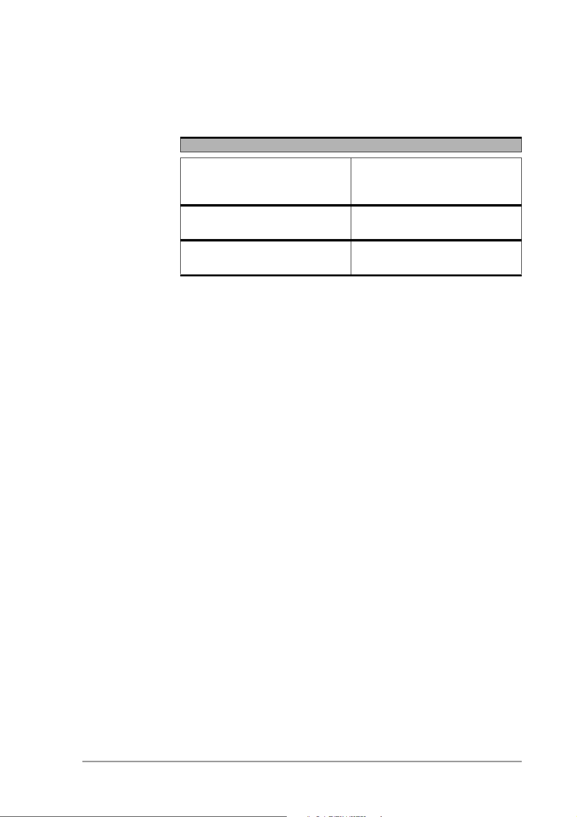
Physical Dimensions
Height 109 mm, with antennas extended
189 mm
Width 105 mm
Depth 31 mm
555004.doc
37
Page 38

Technical specifications 11 Mbps WLAN Access
Point
Other specifications
38
version 1.0
Page 39

6 Regulatory notes and
statements
6.1 Wireless LAN, Health and Authorization for use
Radio frequency electromagnetic energy is emitted from Wireless LAN
devices. The energy levels of these emissions however are far much
less than the electromagnetic energy emissions from wireless devices
like for example mobile phones. Wireless LAN devices are safe for use
by consumers, because they operate within the guidelines found in radio
frequency safety standards and recommendations. The use of Wireless
LAN devices may be restricted in some situations or environments for
example:
• On board of airplanes, or
• In an explosive environment, or
• In case the interference risk to other devices or services is perceived
or identified as harmful.
In case the policy regarding the use of Wireless LAN devices in specific
organizations or environments (e.g. airports, hospitals, chemical/oil/gas
industrial plants, private buildings etc.) is not clear, please ask for
authorization to use these devices prior to operating the equipment.
6.2 Regulatory Information/disclaimers
Installation and use of this Wireless LAN device must be in strict
accordance with the instructions included in the user documentation
provided with the product. Any changes or modifications made to this
device that are not expressly approved by the manufacturer may void
the user’s authority to operate the equipment. The Manufacturer is not
responsible for any radio or television interference caused by
unauthorized modification of this device, or the substitution or
attachment of connecting cables and equipment other than manufacturer
specified. It is the responsibility of the user to correct any interference
caused by such unauthorized modification, substitution or attachment.
Manufacturer and its authorized resellers or distributors will assume no
liability for any damage or violation of government regulations arising
from failing to comply with these guidelines.
6.3 USA-FCC (Federal Communications Commission) statement
555004.doc
This device complies with Part 15 of FCC Rules.
Operation is subject to the following two conditions:
1. This device may not cause interference, and
2. this device must accept any interference, including interference that
may cause undesired operation of this device.
39
Page 40

Regulatory notes and statements
FCC Radio Frequency Exposure statement
6.4 FCC Radio Frequency Exposure statement
This Wireless LAN radio device has been evaluated under FCC Bulletin
OET 65C and found compliant to the requirements as set forth in CFR
47 Sections 2.1091, 2.1093, and 15.247 (b) (4) addressing RF Exposure
from radio frequency devices. The radiated output power of this Wireless
LAN device is far below the FCC radio frequency exposure limits.
Nevertheless, this device shall be used in such a manner that the
potential for human contact during normal operation is minimized. When
using this device, a certain separation distance between antenna and
nearby persons has to be kept to ensure RF exposure compliance. In
order to comply with RF exposure limits established in the ANSI C95.1
standards, the distance between the antennas and the user should not
be less than 30 cm (12 inches).
6.5 FCC Interference Statement
This equipment has been tested and found to comply with the limits for a
Class B digital device, pursuant to Part 15 of the FCC Rules. These
limits are designed to provide reasonable protection against harmful
interference in a residential installation.
This equipment generates, uses, and can radiate radio frequency
energy. If not installed and used in accordance with the instructions, it
may cause harmful interference to radio communications. However,
there is no guarantee that interference will not occur in a particular
installation.
If this equipment does cause harmful interference to radio or television
reception, which can be determined by turning the equipment off and on,
the user is encouraged to try and correct the interference by one or more
of the following measures:
1. Reorient or relocate the receiving antenna.
2. Increase the distance between the equipment and the receiver.
3. Connect the equipment to an outlet on a circuit different from that to
which the receiver is connected.
4. Consult the dealer or an experienced radio/TV technician for help.
6.6 Export restrictions
This product or software contains encryption code which may not be
exported or transferred from the US or Canada without an approved US
Department of Commerce export license.
40
version 1.0
Page 41

Regulatory notes and statements Europe - EU R&TTE Declaration of Conformity
6.7 Europe - EU R&TTE Declaration of Conformity
This Wireless LAN Radio device is tested to and conforms with the
essential radio test suites included in following standards:
Standard Description
EN 60950,ed.
(1992),
incl. A1(1993),
A2(1993),
A3(1995) and
A4(1997)
ETSI EN 300 328
Part 1 V1.2.2
(2000-07)
Part 2 V1.1.1
(2000-07)
ETSI EN 301 489
Part 1 V1.2.1
(2000-08)
Safety of information technology equipment, including electrical
business equipment.
Electromagnetic compatibility and Radio spectrum Matters (ERM);
Wideband Transmission systems; data transmission equipment
operating in the 2,4 GHz ISM band and using spread spectrum
modulation techniques;
Part 1: Technical characteristics and test conditions
Part 2: Harmonized EN covering essential requirements under article
3.2 of the R&TTE Directive.
Electromagnetic compatibility and Radio spectrum Matters (ERM);
Electromagnetic Compatibility (EMC) standard for radio equipment and
services;
Part 1: Common technical requirements
Part 17 V1.1.1
(2000-09)
555004.doc
Part 17: Specific conditions for Wideband data and HIPERLAN
equipment
and therefore complies with the essential requirements and provisions of
the Directive 1999/5/EC of the European Parliament and of the council
of 9 march 1999 on Radio equipment and Telecommunications Terminal
Equipment and the mutual recognition of their conformity and Annex IV
(Conformity Assessment procedure referred to in article 10(4)).
41
Page 42

Regulatory notes and statements
Restricted Wireless LAN device use in EU
6.8 Restricted Wireless LAN device use in EU
Restricted use of this Wireless LAN device in EU member countries is as
follows:
EU country Local restriction
Belgium
/België
/Belgique
Germany
/Deutschland
Indoor operation allowed in channels 1 to 13 in frequency band 2400-
2483.5MHz. Outdoor operation is limited to 2460-2483.5. Please
contact “Belgisch Instituut voor Post and Telecommunicatie” (BIPT) for
authorization, registration and licensing.
Gebruik binnen gebouwen toegestaan in frequentie band op kanalen 1
tot en met 13 (2400-2483.5MHz). Gebruik buiten gebouwen is
gelimiteerd tot 2460-2483.5MHz. Neem voor registratie of licentie
contact op met “Belgisch Instituut voor Post and Telecommunicatie”
(BIPT).
L'utilisation en intérieur est autorise sur les canaux 1 a 13 (2400 -
2483.5 MHz). L'utilisation en extérieur est limitée au fréquences 2460 -
2483.5 MHz. Pour les autorisations, enregistrements et licences,
veuillez contacter l'IBPT (Belgisch Instituut voor Post en
Telecommunicatie).
Outdoor use allowed only with a license. Please contact
“Regulierungsbehörde für Telekommunikation und Post “ (REGTP) for
authorization, registration and licensing.
Im Freiengebrauch ließ nur mit einer Lizenz. Bitte kontaktes
“Regulierungsbehörde für Telekommunikation und Post “ (REGTP) für
Ermächtigung, Ausrichtung und das Genehmigen.
France Indoor use only, no outdoor use allowed. Only channels 10 to 13 (2457
MHz to 2483.5 MHz respectively) are authorized for indoor use in
France. Operation of this device on any other channel is not allowed.
Indoor installation is required to have a license. Please contact ART
(Autorite de Regulation des Telecommunications. Http://www.arttelecom.fr) for authorization, registration and licensing.
Seuls les canaux 10 a 13 (2457-2483.5MHz) peuvent etre utilises en
France. L'utilisation de ce produit sur d'autres frequences n'est pas
autorisee. Toute utilisation , qu'elle soit interieure ou exterieure est
soumise a autorisation. Vous pouvez contacter l'ART (Autorite de
Regulation des Telecommunications. Http://www.art-telecom.fr) pour la
procedure a suivre.
42
version 1.0
Page 43

Regulatory notes and statements Restricted Wireless LAN device use in EU
Italy
/Italia
Netherlands /
Nederland
Indoor use only, no outdoor use allowed. Indoor installation is required
to have a license. Please contact “Ministero delle Comunicazioni,
Direzione Generale Pianificazione e Gestione Frequenze” (DGPF) for
authorization, registration and licensing.
Usare soltanto all'interno, non e' consentito l'uso all'esterno. E'
necessaria l'installazione interna per ottenere una licenza. Per
ottenere l'autorizzazione, la registrazione e la licenza, contattate l'
“Ministero delle Comunicazioni, Direzione Generale Pianificazione e
Gestione Frequenze” (DGPF).
Indoor operation allowed in frequency band 2400-2483.5MHz. Outdoor
operation is limited to 2451-2471 MHz and is required to have a
license. Please contact “Rijks Dienst Radio communicatie” (RDR) for
authorization, registration and licensing.
Gebruik binnen gebouwen toegestaan in frequentie band
2400-2483.5 MHz. Gebruik buiten gebouwen is gelimiteerd tot
2451-2471 MHz en is gebonden aan een licentie. Neem voor
registratie of licentie contact op met de “Rijks Dienst Radio
communicatie” (RDR).
555004.doc
43
Page 44

Regulatory notes and statements
Restricted Wireless LAN device use in EU
44
version 1.0
Page 45

A TCP and IP settings
A.1 Introduction
Before installing a wireless network device you must analyze your
network environment. The information in this appendix is helpful in
determining which information is needed for a proper installation of such
a device. It also provides a brief description of a typical home
installation.
This appendix explains how devices in a network are identified in order
to communicate with each other. Chapter 3: ‘Configuring the Access
Point’ on page 21 contains the instructions on how to apply this
information to your situation
Table A-1 Overview of this chapter
Section Description
A.2 Communication in a network
A.3 IP configuration
A.4 Setting up a home network
A.2 How do computers communicate in a network
Computers use protocols to communicate to each other. The protocol
that is used between computers (and other network devices) that are
connected to the internet is TCP/IP (Transmission Control Protocol/
Internet Protocol). This is also the main protocol in many other computer
networks.
The internet resembles the telephone network to some extent. Like a
phone number that uniquely identifies one telephone connection, IP
addresses are used to determine to which computer the data must be
sent. An IP address looks like this: 192.168.201.160. Each of the four
groups is represented in the computer by one byte, so only numbers
from 0 to 255 can be used for a group.
IP addresses are meant to be unique worldwide. To achieve this, IP
addresses are assigned (you can’t just start using random addresses,
but you have to ask for them). Usually, your Internet Service Provider will
assign you an IP address or IP address range you can use.
555004.doc
45
Page 46

TCP and IP settings
How do computers communicate in a network
A.2.1 IP address
An IP address consists of two parts. The table below describes these
two parts.
Table A-2 Sections of the IP address
Part Identifies Description
First part
All addresses on
the subnet share
this part of the IP
address.
Second part the individual
The division between network portion and node portion is not obvious
from what the IP address looks like. The division isn’t in a fixed place
either. This is because not all subnets have the same size. Subnets can
be small (16 computers) or very large (16 million computers).
To indicate which part of an IP address is the subnet, and which is the
computer identification, IP uses a Subnet mask.
A.2.2 Subnet mask
The subnet mask defines which IP addresses are ‘local’ (i.e. are part of
your subnet) and which are not local (but have to be reached via the
internet). Compare this to calling someone via telephone: you can reach
‘local’ numbers by just entering the subscriber’s number, but for numbers
that aren’t local you need the area code plus the subscriber’s number.
subnet (local
network) to which
the computer is
attached
device
This part of the address is
also known as the ‘network
portion’. It is similar to the
area code of a telephone
number.
This part of the address is
also known as the ‘node
portion’. It is like the
subscriber number in a
telephone number.
46
The subnet mask looks like an IP address. When you translate the
subnet mask to a binary number, it breaks down into two sections: first a
series of 1s and then a series of zeroes (e.g. a subnet mask of
255.255.255 . 0 tr anslates to 11111111.11111111. 11111111.00000000). The
1s identify the network portion, the zeroes identify the node portion of the
address. The subnet mask in this example has 8 bits available for local
addresses (i.e. 256 different local addresses can be used).
An example: on a computer, the network settings are defined with an IP
address of 192.168.201.173 and a subnet mask of 255.255.255.224.
These would be represented in binary like this:
version 1.0
Page 47

TCP and IP settings How do computers communicate in a network
IP address:
11000000.10101000.11001001.10101101
subnet mask:
11111111.11111111.11111111.11100000
The subnet mask shows that the first 27 bits are the network portion of
the address, the last 5 bits are the node portion, which means there is
room for 32 addresses on this network (all numbers between 00000 and
11111 in binary).
A.2.3 IP address range
All addresses in this network share the first 27 bits. The first address in
the local network is 192.168.201.160. The last address is
192.168.201.191. In binary:
First address:
11000000.10101000.11001001.10100000
Last address:
11000000.10101000.11001001.10111111
Such a group of addresses is also called an IP address range.
A.2.4 Reserved addresses
The first and last addresses in a range cannot be assigned to computers
in your network. These addresses have special functions.
The first address in a range is also known as the network address, the
last address is the broadcast address.
Subnet masks are sometimes written down as 192.168.201.160/27,
where 192.168.201.160 is the first address (or ‘network address’) in the
range, and 27 is the number of 1s in the binary representation of the
subnet mask (this subnet mask can also be written as 255.255.255.224).
A.2.5 Gateway
If a device wants to communicate with another device it will determine if
that IP address is in the same subnet as its own IP address. If it is, it can
communicate directly with the other, if it isn’t, the situation is more
complicated; it has to communicate with another subnet.
555004.doc
To communicate between subnets there has to be a connection between
the 2 subnets. This connection is made via devices known as gateways.
If a device wants to communicate with a device in another subnet it
sends the information to the gateway, and the gateway takes care of the
rest of the transport.
47
Page 48

TCP and IP settings
IP configuration
In order to do this, the sender needs to have the IP address of the
gateway for his subnet. Normally, the lowest available node number in
the subnet (the network address plus one) is used as the gateway
address.
A gateway can be a dedicated device, or a software package on one of
the computers in your network. The gateway has two network
connections, one for each network. One supplier of gateway software is
Sygate (www.sygate.com).
A.2.6 MAC address
Every Ethernet device has a unique address that is permanently linked
to that device. It cannot be changed. On most wireless devices, the MAC
address is printed on its type label.
The MAC address consists of six groups of two digits each (e.g.
00:10:91:00:00:00).
A.3 IP configuration
The most basic way to configure IP settings is by entering the numbers
manually on every host. This is somewhat complicated because every
host in the subnet has to have the same subnet number but a unique
node number. Also, the correct Subnet mask will have to be entered. Not
doing this properly will result in errors.
To simplify managing an IP network, several automated methods have
been introduced. The two most important ones are DHCP and Auto IP.
A.3.1 DHCP
When a network uses DHCP (Dynamic Host Configuration Protocol),
one host in the network contains a DHCP server. Whenever a device
joins the network it asks the DHCP server for an IP configuration.
The DHCP server sends back a unique IP address, the Subnet mask for
this subnet and the IP address of the Gateway. The DHCP server keeps
track of which hosts have requested an IP address and which IP they
have been given.
For large networks, DHCP is a convenient way of managing IP
configurations, but in small networks the benefits often do not
compensate the overhead of installing and managing the DHCP server.
48
A.3.2 Auto IP
Auto IP, also known as APIPA (Automatic Personal IP Assignment) is a
method in which no server is needed.
version 1.0
Page 49

TCP and IP settings Setting up a home network and connecting it to the internet
Every host that joins the network will look for a unique node number in
the subnet 169.254.___.___ (i.e. network address is 169.254.0.0,
Subnet mask is 255.255.000.000).
The host will do this by randomly choosing a node number and then
checking to make sure no other host is using that IP address. If the IP
address is already in use, the host will try again with another random IP
number.
Auto IP can only be used on a non-routed network. You cannot use this
method if you want to connect to other networks or the internet.
When a host joins a network will look for a DHCP server first. If none is
available, it will use Auto IP instead.
A.4 Setting up a home network and connecting it to the internet
A typical scenario is that a user has a few computers and wants to:
• network the computers,
• connect to the internet from each computer.
To realize this, you need to set up your network as follows:
1. Install a gateway (see section A.2.5: ‘Gateway’ on page 47).
2. Connect the gateway to your internet connection.
3. Connect the gateway to your Access Point.
4. Install WLAN cards in your clients.
5. Configure the clients to connect to the Access Point and the gateway.
555004.doc
49
Page 50

TCP and IP settings
Setting up a home network and connecting it to the internet
50
version 1.0
Page 51

B Wireless LAN
B.1 Introduction
This Appendix explains some of the basic terms and concepts of
Wireless LANs.
See the specifications of your device for details on the performance of
your device
Table B-1 Contents of Appendix B. Wireless LANs
Section Description
B.2 This section explains the basic features of a
B.3 This section explains the basic features of an
Wireless LAN.
Access Point.
B.4 Wireless LANs require an extra identification: the
B.5 This section describes some of the physics of an
B.6 Wireless LANs require extra security on
B.2 Wireless LAN
Wireless LANs transmit and receive data through the air through radio
frequency (RF) technology, minimizing the need for wired connections.
Wireless LANs use Access Points (see section B.3: ‘The Access
Point’ on page 52) to connect computers to each other and to the wired
network.
Through Wireless LANs, you can access shared information without
looking for a place to plug in. A network administrators can install or
expand networks without installing or moving wires.
A wireless LAN is transparent: applications function just like they would
on a wired LAN.
Service Set Identification.
Access Point
eavesdropping. This section describes some of the
security methods.
555004.doc
Most importantly: to use a wireless LAN, you do not need to be an
expert. All you have to do is to find an Access Point in the range of your
laptop and connect.
51
Page 52

Wireless LAN
The Access Point
B.3 The Access Point
An Access Point is similar to a hub. It connects computers to each other
and to a network. Unlike a hub, an Access Point is a node on the
network, with its own IP address. Only the Access Points on a Wireless
LAN require cabling.
An Access Point in itself cannot give access to the internet. You need a
gateway (see section A.2.5: ‘Gateway’ on page 47) to connect to the
internet.
B.4 Service Set ID (SSID)
The Service Set ID is the name of your wireless network that you
connect to. Several wireless LANs, each with its own SSID, can be
operational in an area. Multiple Access Point can share the same SSID.
Your network client allows you to choose which network you join.
B.5 Physics of an Access Point
B.5.1 Range
A wireless LAN device uses RF waves (Radio Frequency) to transmit
and receive data. The range of the propagated power depends on the
device and the environment. Indoor environments contain objects such
as walls, metal objects, and even people that can effect the propagation
of the radiated power.
Although RF energy can penetrate through most indoor walls and other
obstacles, these obstacles may influence the quality of the signal of the
wireless device.
When placing wireless LAN device you must consider all possible
obstacles and test the range of the device using a client device to make
a connection and moving around to test the strength of the signal.
When you place more than one wireless LAN device, consider the range
that each device covers.
For the range of your device(s); see the specifications of your device.
52
B.5.2 Data rates
Wireless LAN devices operate at much faster speeds than modems.
The data rates on a wireless link are determined by:
• the range of the device,
• proper propagation of the signal ((conducting) obstacles,),
version 1.0
Page 53

Wireless LAN Security
• interference of other devices,
• number of users.
Some devices can handle more than one data rate; see the
specifications of your device.
B.5.3 Regulatory Domain
Every region or country has a regulatory body which governs the use of
radio channels. Such a region is called a regulatory domain.
Europe (excluding France) is governed by the ETSI (the European
Telecommunications Standards Institute). In the United States of
America, the FCC (Federal Communications Commission) fulfils this
role.
The radio channels (see section B.5.4: ‘Radio Channels’ on page 53)
you can use depend on your regulatory domain.
A wireless LAN uses a spectrum of radio frequencies for which no enduser license is needed.
B.5.4 Radio Channels
Each Access Point in the network forms the center of a cell, i.e. an area
in which the radio signal of an Access Point is sufficient to join the
network.
The radio channels that you are allowed to use depend on both the
capabilities of the PC cards you are deploying, as well as the regulations
in your area (see section B.5.3: ‘Regulatory Domain’ on page 53).
For a single Access Point you can choose any of the available channels.
However, when there are more Access Points in the neighborhood, they
must send and receive preferably on different channels for a maximum
throughput. The cells should overlap slightly to guarantee seamless
wireless connectivity everywhere.
B.6 Security
555004.doc
Wired LANs require security techniques to prevent unauthorized access
to and management of the network.
Security on a Wireless LAN requires additional techniques to protect
from eavesdroppers that want to listen in on the Wireless LAN traffic.
Every node (Access Point, PC card) in a wireless network must be
secured against eavesdropping.
To get a secure network, two techniques are used:
53
Page 54

Wireless LAN
Security
• authentication: clients must identify themselves before they can
• encryption: data is sent across the network in such a way it cannot
B.6.1 WEP
The IEEE 802.11 standard includes a shared key data privacy
mechanism, called 'Wired Equivalent Privacy'.
Only devices that share the same WEP key are allowed to communicate
with each other.
Features of WEP are:
• Data encryption using a
access the network,
be read unless you have the correct ‘key’.
- 40 bit shared key (key is 10 hexadecimal characters), or
- 104-bit shared key (key is 26 hexadecimal characters).
• No key distribution mechanism. The shared key (password) must be
distributed manually to all personnel and either be remembered or
stored somewhere on the hard disk.
• Simple authentication of clients based on hardware address.
Other authentication methods may have been delivered for different
types of Wireless LAN devices.
54
version 1.0
Page 55

Index
A
Access Control List 27
Access Point 51, 52
Allow clients 28
APIPA 48
Auto IP 48
B
Bit rates 35
Broadcast address 47
C
Contact 23, 31
D
Data rates 52
Deny clients 28
DHCP 48
Dynamic IP settings 24
E
exception list 28
G
Gateway 24, 47
I
IP address 23, 45, 46
IP address range 45
IP settings 31
K
KickStart 22
O
Open Systems 29
P
Power LED 18
R
Radio channel 27, 36, 53
Radio LED 18
Radio specifications 36
Range 36, 52
Regulatory domain 27, 53
Reset Access Point 19
S
Security 53
SSID 23, 27
Static IP settings 24
Subnet 46
Subnet mask 46
T
TCP/IP 23
U
Unlock Access Point 18
UTP port 17
W
Web Interface 25
WEP 29, 54
Wired connection 17
Wireless LAN 51
555004.doc
L
Location 23, 31
Lock Access Point 30
M
MAC address 23, 31, 48
N
Network address 47
Network LED 18
Network portion 46
Node portion 46
55
Page 56

Index
56
version 1.0
 Loading...