

Page 1

TL431/TL431A/TL431B
P
RECISION PROGRAMMABLE REFERENCES
T HE I NFINITE P OWER OF I NNOVATION
DESCRIPTION KEY FEATURES
The TL431/TL431A/TL431B series
precision adjustable three terminal shunt
voltage regulators are pin-to-pin
compatible with the industry standard
TL431. The output voltage of this
reference is programmable by using two
external resistors from 2.5V to 36V.
These devices offer low output
NOTE: For current data & package dimensions, visit our web site: http://www.linfinity.com.
PRODUCT HIGHLIGHT
impedance for improved load regulation.
The typical output impedance of these
devices is 200mΩ. These devices find
application in the feedback path of
switching power supplies, OVP
crowbar circuits, reference for A/D,
D/A, and as zener diodes with
improved turn-on characteristics.
P RECISION PROGRAMMABLE REFERENCES
V
IN
V
OUT
P RODUCTION DATA SHEET
W INITIAL VOLTAGE REFERENCE ACCURACY OF
0.4% (TL431B)
W SINK CURRENT CAPABILITY 1mA to 100mA
W TYPICAL OUTPUT DYNAMIC IMPEDANCE
LESS THAN 200mΩ;
TYPICAL OUTPUT IMPEDANCE OF THE
TL431B LESS THAN 100mΩ
W ADJUSTABLE OUTPUT VOLTAGE FROM 2.5V
TO 36V
W AVAILABLE IN SURFACE-MOUNT PACKAGES
W LOW OUTPUT NOISE
W TYPICAL EQUIVALENT FULL RANGE
TEMPERATURE COEFFICIENT OF 30ppm/°C
W DIRECT PIN-TO-PIN REPLACEMENT FOR
INDUSTRY STANDARD TL431 AND TL1431
TL431/A
& TL431B
0 to 70 1% TL431ACDM TL431ACLP
-40 to 85 1% TL431AIDM TL431AILP
R1
VO = 1 +
R2
*
R1
R2
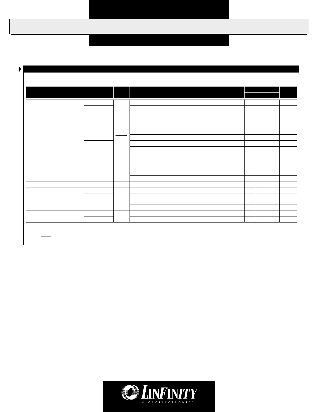
PACKAGE ORDER INFORMATION
T
(°C)
A
Initial
Tolerance
2% TL431CDM TL431CLP
0.4% TL431BCDM TL431BCLP
2% TL431IDM TL431ILP
0.4% TL431BIDM TL431BILP
Note: All surface-mount packages are available in Tape & Reel.
Append the letter "T" to part number. (i.e. TL431CDMT)
TO-92 (LP) package also available in ammo-pack.
Plastic SOIC
DM
8-pin
LP
V
REF
Plastic TO-92
3-pin
Copyright © 1999
Rev. 1.3 9/99
L INF INITY MICROELECTRONICS INC.
11861 WESTERN AVENUE, GARDEN GROVE, CA. 92841, 714-898-8121, FAX: 714-893-2570
1
Page 2

PRODUCT DATABOOK 1996/1997
TL431/TL431A/TL431B
P
RECISION PROGRAMMABLE REFERENCES
P RODUCTION DATA SHEET
ABSOLUTE MAXIMUM RATINGS (Note 1)
Cathode to Anode Voltage (VKA) (Note 2) .................................................... -0.3V to 37V
Reference Input Current (I
Continuous Cathode Current (I
Operating Junction Temperature
) ................................................................... -50µA to 10mA
REF
) ......................................................... -100mA to 150mA
K
Plastic (DM, LP Packages) .................................................................................... 150°C
Storage Temperature Range ...................................................................... -65°C to 150°C
Lead Temperature ..................................................................................................... 300°C
Note 1. Exceeding these ratings could cause damage to the device. All voltages are with respect
Note 2. Voltage values are with respect to the anode terminal unless otherwise noted.
to Ground. Currents are positive into, negative out of the specified terminal. Pin
numbers refer to DIL packages only.
THERMAL DATA
DM PACKAGE:
THERMAL RESISTANCE-JUNCTION TO AMBIENT,
θθ
θ
θθ
JA
165°C/W
LP PACKAGE:
D
x θ
θθ
θ
θθ
JA
).
JA
156°C/W
THERMAL RESISTANCE-JUNCTION TO AMBIENT,
Junction Temperature Calculation: TJ = TA + (P
The θ
numbers are guidelines for the thermal performance of the device/pc-board system.
JA
All of the above assume no ambient airflow
BLOCK DIAGRAM
PACKAGE PIN OUTS
CATHODE
N.C.
ANODE
N.C.
1 8
2 7
3 6
4 5
DM PACKAGE
(Top View)
LP PACKAGE
(Top View)
REF
ANODE
ANODE
N.C.
1. CATHODE
2. ANODE
3. REF
Ref (R)
Cathode (K)
V
REF
Anode (A)
2
Copyright © 1999
Rev. 1.3 9/99
Page 3
PRODUCT DATABOOK 1996/1997
TL431/TL431A/TL431B
P
RECISION PROGRAMMABLE REFERENCES
P RODUCTION DATA SHEET
ELECTRICAL CHARACTERISTICS (Note 3)
(Unless otherwise specified, these specifications apply over the operating ambient temperatures for TL431C/TL431AC/TL431BC with 0°C ≤ TA ≤ 70°C,
TL431I/TL431AI/TL431BI with -40°C ≤ TA ≤ 85°C.)
Parameter
Reference Input Voltage TL431 V
TL431A I
TL431B IK = 10mA, VKA = V
Reference Drift TL431C IK = 10mA, VKA = V
TL431I IK = 10mA, VKA = V
TL431AC ∆V
TL431AI ∆V
TL431BC IK = 10mA, VKA = V
TL431BI IK = 10mA, VKA = V
Symbol
REFIK
REFIK
KAIK
= 10mA, VKA = V
= 10mA, VKA = V
K
= 10mA, VKA = V
= 10mA, VKA = V
Test Conditions
, TA = 25°C
REF
, TA = 25°C
REF
, TA = 25°C
REF
REF
REF
REF
REF
REF
REF
Voltage Ratio, Ref to Cathode TL431, TL431A IK = 10mA, VKA = 2.5V to 36V
(Note 4) TL431B IK = 10mA, VKA = 2.5V to 36V
Reference Input Current TL431,TL431A I
REFVKA
TL431B
Minimum Operating Current I
Off-State Cathode Current TL431 I
MINVKA
OFFVKA
TL431A VKA = V
TL431B
Dynamic Impedance TL431 | ZKA |VKA = V
TL431B VKA = V
= V
, TA = 25°C
REF
VKA = V
, TA = 25°C
REF
VKA = V
, TA = Operating Range
REF
= V
to 36V
REF
= V
to 36V, TA = 25°C
REF
to 36V, TA = 25°C
REF
VKA = V
to 36V, TA = Operating Range
REF
VKA = 36V, V
= 0V, TA = 25°C
REF
, I
= 1mA to 100mA, f ≤ 1kHz, T
REF
K
, I
= 1mA to 100mA, f ≤ 1kHz, T
REF
K
Note 3. These parameters are guaranteed by design.
∆V
Note 4. Ratio of change in reference input voltage
REF
∆V
KA
to the change in cathode voltage.
= 25°C
A
= 25°C
A
TL431/431A/431B
Min. Typ. Max.
Units
2440 2495 2550 mV
2470 2495 2520 mV
2490 2500 2510 mV
417 mV
530 mV
417 mV
530 mV
415 mV
520 mV
-1.4 -2.7 mV/V
-1.1 -2 mV/V
24 µA
1.5 1.9 µA
2.3 µA
0.4 1 mA
0.1 1 µA
0.1 1 µA
2µA
0.18 0.5 µA
0.2 0.5 Ω
0.1 0.2 Ω
Copyright © 1999
Rev. 1.3 9/99
3
Page 4

PRODUCT DATABOOK 1996/1997
TL431/TL431A/TL431B
P
RECISION PROGRAMMABLE REFERENCES
P RODUCTION DATA SHEET
GRAPH / CURVE INDEX FIGURE INDEX
Characteristic Curves
FIGURE #
1. REFERENCE INPUT VOLTAGE vs. FREE-AIR TEMPERATURE
2. REFERENCE INPUT CURRENT vs. FREE-AIR TEMPERATURE
3. CATHODE CURRENT vs. CATHODE VOLTAGE
4. CATHODE CURRENT vs. CATHODE VOLTAGE
5. OFF-STATE CATHODE CURRENT vs. FREE-AIR TEMPERATURE
6. RATIO OF DELTA REFERENCE VOLTAGE TO DELTA CATHODE
VOLTAGE vs. FREE-AIR TEMPERATURE
7. EQUIVALENT INPUT NOISE VOLTAGE vs. FREQUENCY
Parameter Measurement Information
FIGURE #
8. TEST CIRCUIT FOR V
9. TEST CIRCUIT FOR VKA > V
10. TEST CIRCUIT FOR I
= V
KA
REF
REF
OFF
Typical Characteristics
FIGURE #
11. EQUIVALENT INPUT NOISE VOLTAGE OVER A 10-SECOND PERIOD
12. SMALL-SIGNAL VOLTAGE AMPLIFICATION vs. FREQUENCY
13. REFERENCE IMPEDANCE vs. FREQUENCY
14. PULSE RESPONSE
15. STABILITY BOUNDARY CONDITIONS
Application Information
FIGURE #
16. SHUNT REGULATOR
17. SINGLE-SUPPLY COMPARATOR WITH TEMPERATURE-COMPENSATED
THRESHOLD
18. HIGH CURRENT SHUNT REGULATOR
19. CROWBAR CIRCUIT
20. VOLTAGE MONITOR
21. PRECISION CONSTANT-CURRENT SINK
4
Copyright © 1999
Rev. 1.3 9/99
Page 5

PRODUCT DATABOOK 1996/1997
0
-200
(VKA) Cathode Voltage - (V)
800
(I
K
) Cathode Current - (µA)
200
-1 0
1
23
400
I
MIN
600
VKA = V
REF
TA = 25°C
TL431/TL431A/TL431B
P
RECISION PROGRAMMABLE REFERENCES
P RODUCTION DATA SHEET
CHARACTERISTIC CURVES
FIGURE 1. — REFERENCE VOLTAGE
vs. FREE-AIR TEMPERATURE
2.60
V
= V
REF
2.58
KA
IK = 10mA
2.56
TL431/A
2.54
2.52
TL431B
2.50
2.48
TL431/A
2.46
) Reference Input Voltage - (V)
2.44
REF
(V
TL431/A
2.42
2.4
-50 -25 0
25
(TA) Ambient Temperature - (°C)
V
= 2550mV
REF
V
= 2495mV
REF
V
= 2440mV
REF
50 75 100 125
FIGURE 2. — REFERENCE CURRENT
vs. FREE-AIR TEMPERATURE
5
IK = 10mA
R1 =
4
3
IK = 10mA
TL431/A
2
TL431B
1
) Reference Input Current - (µA)
REF
(I
0
-25 0
-50
25
(TA) Ambient Temperature - (°C)
50 75 100 125
FIGURE 3. — CATHODE CURRENT vs. CATHODE VOLTAGE FIGURE 4. — CATHODE CURRENT vs. CATHODE VOLTAGE
150
125
100
75
50
Copyright © 1999
Rev. 1.3 9/99
25
0
) Cathode Current - (µA)
K
(I
TL431/A
-25
-50
-75
-100
-2 -1 0
VKA = V
REF
TA = 25°C
TL431B
(VKA) Cathode Voltage - (V)
1
23
5
Page 6

PRODUCT DATABOOK 1996/1997
TL431/TL431A/TL431B
P
RECISION PROGRAMMABLE REFERENCES
P RODUCTION DATA SHEET
CHARACTERISTIC CURVES
FIGURE 5. — OFF-STATE CATHODE CURRENT
vs. FREE-AIR TEMPERATURE
2.5
VKA = 36V
V
= 0
REF
2
1.5
1
0.5
) Off-State Cathode Current - (µA)
OFF
(I
0
-50 -25 0
25
50 75 100 125
TL431/A
& TL431B
(TA) Ambient Temperature - (°C)
FIGURE 7. — EQUIVALENT INPUT NOISE VOLTAGE
vs. FREQUENCY
260
FIGURE 6. — RATIO OF DELTA REFERENCE VOLTAGE TO DELTA
CATHODE VOLTAGE vs. FREE-AIR TEMPERATURE
-0.85
VKA = 3V to 36V
-0.95
-1.05
- (mV/V)
KA
-1.15
V
∆
/
REF
V
-1.25
∆
-1.35
-1.45
-50
-25 0
25
50 75 100 125
(TA) Ambient Temperature - (°C)
240
220
200
180
160
140
) Noise Voltage - (nV/ Hz)
N
IO = 10mA
T
= 25°C
A
(V
120
100
10 100
1k
10k 100k
(f) Frequency - (Hz)
6
Copyright © 1999
Rev. 1.3 9/99
Page 7

PRODUCT DATABOOK 1996/1997
A
A
A
TL431/TL431A/TL431B
P
RECISION PROGRAMMABLE REFERENCES
P RODUCTION DATA SHEET
PARAMETER MEASUREMENT INFORMATION
Input
V
REF
FIGURE 8 — TEST CIRCUIT FOR VKA = V
I
K
Input
V
K
REF
I
OFF
Input
R
1
I
REF
R
FIGURE 9 — TEST CIRCUIT FOR VKA > V
V
V
2
K
REF
I
K
V
K
REF
Copyright © 1999
Rev. 1.3 9/99
FIGURE 10 — TEST CIRCUIT FOR I
OFF
7
Page 8

PRODUCT DATABOOK 1996/1997
(t)
)
TL431/TL431A/TL431B
P
RECISION PROGRAMMABLE REFERENCES
P RODUCTION DATA SHEET
TYPICAL CHARACTERISTICS
6
5
4
3
2
1
0
-1
-2
-3
) Input Noise Voltage - (µV)
N
-4
(V
-5
-6
0
f = 0.1 to 10Hz
I
= 10mA
K
= 25°C
T
A
2
4
68
10
500µF
Time - (s
FIGURE 11. — EQUIVALENT INPUT NOISE VOLTAGE OVER A 10-SECOND PERIOD
19.1V
1k
V
910
2000µF
2000µF
TL431/A
& TL431B (DUT)
820
16
0.1µF
CC
TLE2027
A
160k
V
EE
= 10V/mV
V
16k
V
CC
1µF
TLE2027
16k
1µF
33k
33k
AV = 2V/V
V
EE
Test Circuit for 0.1Hz to 10Hz Equivalent Input Noise Voltage
1M
2.2µF
CRO
8
Copyright © 1999
Rev. 1.3 9/99
Page 9

PRODUCT DATABOOK 1996/1997
(f)
)
(f)
)
t
P
RECISION PROGRAMMABLE REFERENCES
P RODUCTION DATA SHEET
TYPICAL CHARACTERISTICS
FIGURE 12. — SMALL-SIGNAL VOLTAGE AMPLIFICATION
vs. FREQUENCY
70
IK = 10mA
= 25°C
60
50
T
A
TL431/TL431A/TL431B
Output
I
K
230
15k
40
30
20
10
) Voltage Amplification - (dB)
V
(A
0
-10
1k 100k
10k 1M
Frequency - (Hz
FIGURE 13. — REFERENCE IMPEDANCE vs. FREQUENCY
100
)
IK = 1mA to 100mA
T
= 25°C
A
10
10M
9µF
8.25k
Test Circuit for Voltage Amplification
1k
50
GND
Outpu
I
K
|) Reference Impedance - (
KA
(|z
Copyright © 1999
Rev. 1.3 9/99
1
0.1
1k 100k
10k
Frequency - (Hz
GND
1M 10M
Test Circuit for Reference Impedance
9
Page 10

PRODUCT DATABOOK 1996/1997
t
TL431/TL431A/TL431B
P
RECISION PROGRAMMABLE REFERENCES
P RODUCTION DATA SHEET
TYPICAL CHARACTERISTICS
FIGURE 14. — PULSE RESPONSE
6
5
4
- (V)
3
IN
V
2
1
0
Pulse
Generator
f = 100kHz
220
50
Outpu
3
)
2
KA
(V
1
0
Output Voltage - (V)
05
2134
(t) Time - (µs)
FIGURE 15. — STABILITY BOUNDARY CONDITIONS
100
90
80
70
60
A VKA = V
B VKA = 5V
C V
D V
= 10V
KA
= 15V
KA
REF
Stable
A*
50
40
30
) Cathode Current - mA
K
(I
20
10
B*
C*
D*
IK = 10mA
T
A
Stable
= 25°C
GND
Test Circuit for Pulse Response
6
I
R1=10k
C
L
R2
K
150
V
BATT
Test Circuit for Curve A
150
I
K
0
0.001
0.01 0.1 1 10
(CL) Load Capacitance - (µF)
* The areas under the curves represent conditions that may cause the
device to oscillate. For curves B, C, and D, R2 and V+ were adjusted to
establish the initial VKA and IK conditions with CL = 0. V
then adjusted to determine the ranges of stability.
BATT
10
and CL were
C
L
Test Circuit for Curves B, C, and D
V
BATT
Copyright © 1999
Rev. 1.3 9/99
Page 11

B
V
BATT
V
O
V
T
R (see Note)
R1 0.1%
V
REF
R2 0.1%
PRODUCT DATABOOK 1996/1997
TL431/TL431A/TL431B
P
RECISION PROGRAMMABLE REFERENCES
P RODUCTION DATA SHEET
APPLICATION INFORMATION
V
O
I
K
TL431/A
TL431/A
& TL431
Input
& TL431B
V
BATT
V
O
2V
V
ON
V
V
OFF
BAT
VO = 1 +
Note: R should provide ≥ 1mA cathode current to
the TL431/A & TL1431 at minimum V
FIGURE 16 — SHUNT REGULATOR FIGURE 17 — SINGLE-SUPPLY COMPARATOR WITH
BATT
R2
V
*
REF
R1
R1
R2
TL431/A
& TL431B
BATT
GND
.
TEMPERATURE-COMPENSATED THRESHOLD
V
BATT
V
O
R1
TL431/A
& TL431B
C
R2
(see Note)
VO = 1 +
Copyright © 1999
Rev. 1.3 9/99
FIGURE 18 — HIGH CURRENT SHUNT REGULATOR FIGURE 19 — CROWBAR CIRCUIT
R2
V
*
REF
R1
Note: Refer to the stability boundary conditions in
Figure 15 to determine allowable values for C.
11
Page 12

PRODUCT DATABOOK 1996/1997
%
T
&
TL431/TL431A/TL431B
P
RECISION PROGRAMMABLE REFERENCES
P RODUCTION DATA SHEET
APPLICATION INFORMATION
12V
R3 (see Note)
R1A
R4
(Note)
TL431/A
& TL431B
R2A
R1B
Low Limit = 1 +
High Limit = 1 +
Note: R3 and R4 are selected to provide the desired LED intensity and ≥ 1mA
cathode current to the TL431/A & TL431B at the available V+.
R2B
R1B
R2B
FIGURE 20 — VOLTAGE MONITOR FIGURE 21 — PRECISION CONTANT-CURRENT SINK
R2B
V
*
REF
V
*
REF
LED On when
Low Limit < V
< High Limit
BATT
L431/A
TL431B
V
BATT
IO =
I
O
R
S
0.1
V
REF
R
S
12
PRODUCTION DATA - Information contained in this document is proprietary to LinFinity, and is current as of publication date. This document
may not be modified in any way without the express written consent of LinFinity. Product processing does not necessarily include testing of
all parameters. Linfinity reserves the right to change the configuration and performance of the product and to discontinue product at any time.
Copyright © 1999
Rev. 1.3 9/99
 Loading...