

Page 1

INTEGRATED CIRCUITS
DATA SH EET
TEA1210TS
Highefficiency,highcurrentDC/DC
converter
Product specification
Supersedes data of 1999 Mar 08
File under Integrated Circuits, IC03
2000 Nov 28
Page 2

Philips Semiconductors Product specification
High efficiency, high current DC/DC converter TEA1210TS
FEATURES
• Fully integrated DC/DC converter circuit, featuring
internal very low R
• Up-or-down conversion
• Start-up from 1.85 V input voltage
• Adjustable output voltage
• High efficiency over large load range
• 600 kHz switching frequency
• Low quiescent power consumption
• Synchronizing with external clock
• Two selectable current limits for efficient battery use in
case of dynamic loads
• Up to 100% duty cycle in down mode
• Undervoltage lockout
• Shut-down function
• 16-pin small body SSOP16 package.
APPLICATIONS
• Cellularphones,Personal Digital Assistants(PDAs) and
others
• Supply voltage source for low-voltage chip sets
• Portable computers
• Battery backup supplies.
power MOSFETs
DSon
GENERAL DESCRIPTION
The TEA1210TS is a fully integrated DC/DC converter.
Efficient, compact and dynamic power conversion is
achieved using a novel digitally controlled concept like
Pulse Width Modulation (PWM) or Pulse Frequency
Modulation (PFM), integrated low R CMOS power
switches with low parasitic capacitances, and fully
synchronous rectification.
The device operates at 600 kHz switching frequency
which enables the use of external components with
minimum size. The switching frequency can be locked to
an external high-frequency clock.
Optionally, the device can be kept in the Pulse Width
Modulation (PWM) mode regardless of the load applied.
Deadlock is prevented by an on-chip undervoltage lockout
circuit.
Twoselectablecurrent limits inupconversionmodeenable
efficient battery use even at highly dynamic loads such as
cellular phone electronics.
ORDERING INFORMATION
TYPE NUMBER
NAME DESCRIPTION VERSION
TEA1210TS SSOP16 plastic shrink small outline package; 16 leads; body width 4.4 mm SOT369-1
2000 Nov 28 2
PACKAGE
Page 3
Philips Semiconductors Product specification
High efficiency, high current DC/DC converter TEA1210TS
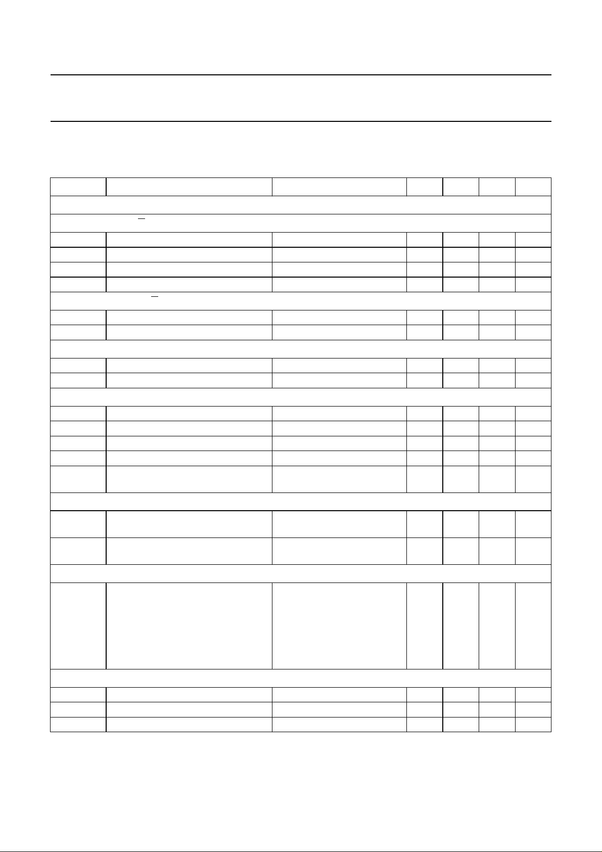
QUICK REFERENCE DATA
T
= −40 to +80 °C; all voltages measured with respect to ground; positive currents flow into the IC; unless otherwise
amb
specified.
SYMBOL PARAMETER CONDITIONS MIN. TYP. MAX. UNIT
Voltage levels
PCONVERSION; PIN U/D = LOW
U
V
I
V
O
V
I(start)
V
I(uvlo)
OWNCONVERSION; PIN U/D = HIGH
D
V
I
V
O
input voltage V
output voltage 2.90 − 5.50 V
start-up input voltage IL< 200 mA 1.20 1.60 1.85 V
undervoltage lockout input voltage 1.50 2.10 2.70 V
input voltage 2.90 − 5.50 V
output voltage 1.30 − 5.50 V
GENERAL
V
∆V
fb
window
feedback input voltage 1.20 1.25 1.30 V
output voltage window PWM mode 1.5 2.0 3.0 %
Current levels
I
q
I
shdwn
∆I
lim(up)
I
lim(down)
I
LX
quiescent current on pins LX VI=2.40 V; VO= 3.60 V 100 125 150 µA
current in shut-down mode − 210µA
current limit deviation in up mode I
current limit in down mode 4.8 A
maximum continuous current on
pins LX
Power MOSFETs
R
DSon(N)
drain-to-source on-state resistance
NFET
R
DSon(P)
drain-to-source on-state resistance
PFET
Efficiency
η efficiency upconversion V
Timing
f
sw
f
sync
t
res
switching frequency PWM mode 480 600 720 kHz
synchronization clock input frequency 9 13 20 MHz
response time from standby to P
set to 2.0 A −12 − +12 %
lim(up)
T
=60°C −−1.8 A
amb
Tj=27°C − 56 63 mΩ
Tj=27°C − 68 77 mΩ
= 2.4 V; VO= 3.6 V;
I
T
=20°C
amb
I
=1mA 83 86 − %
L
I
= 100 mA 90 93 − %
L
I
= 500 mA 92 94 − %
L
I
= 1.5 A; not continual 84 86 − %
L
o(max)
− 25 −µs
− 5.50 V
I(start)
2000 Nov 28 3
Page 4
This text is here in white to force landscape pages to be rotated correctly when browsing through the pdf in the Acrobat reader.This text is here in
_white to force landscape pages to be rotated correctly when browsing through the pdf in the Acrobat reader.This text is here inThis text is here in
white to force landscape pages to be rotated correctly whenbrowsing through the pdf in the Acrobat reader. white to force landscape pages to be ...
2000 Nov 28 4
handbook, full pagewidth
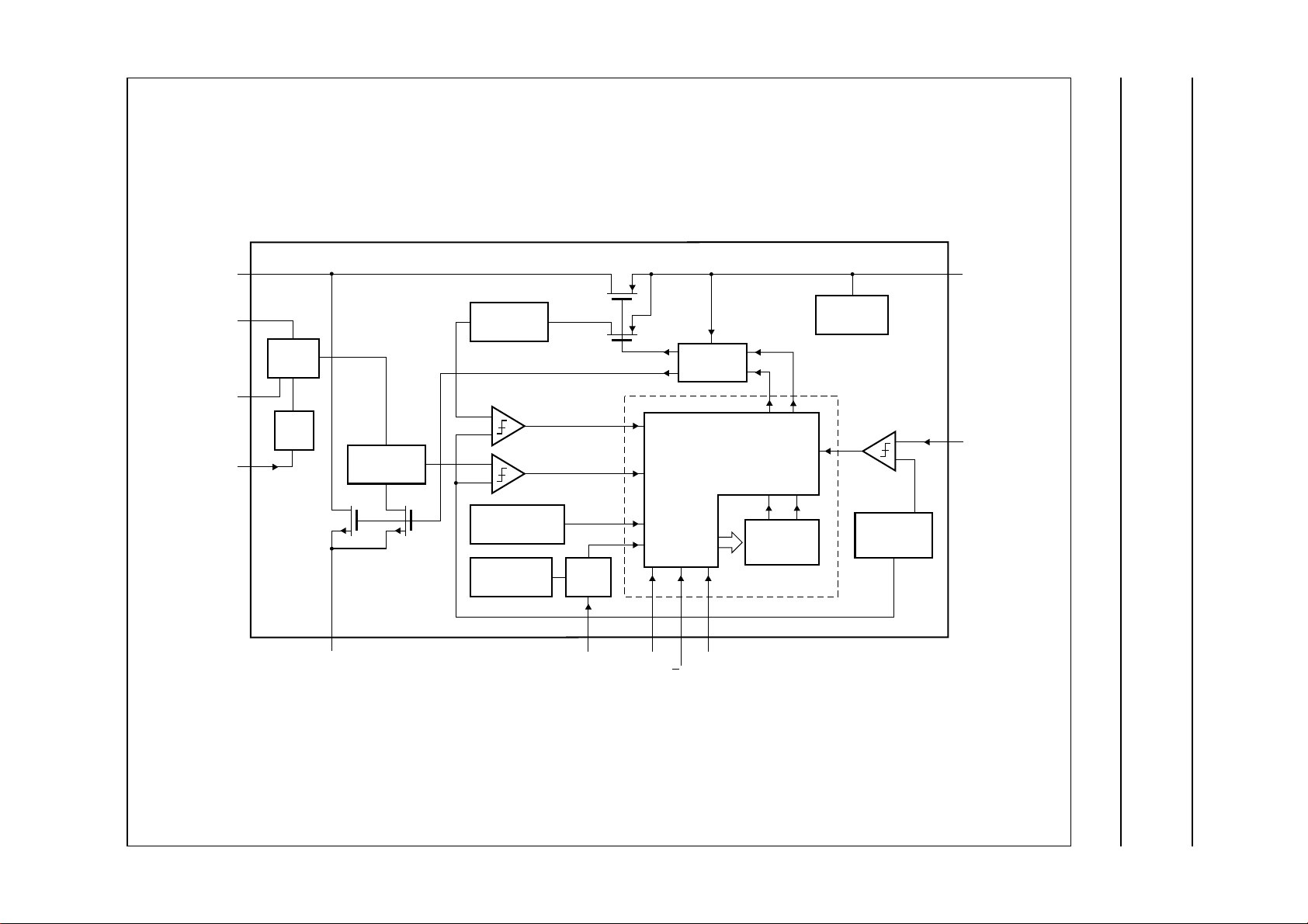
BLOCK DIAGRAM
Philips Semiconductors Product specification
High efficiency, high current DC/DC converter TEA1210TS
LX
ILIMH
ILIML
ILIMSEL
4, 5, 12, 13
7
SWITCH
10
LPF
11
N-type
POWER
FET
GND
I/V
CONVERTER
sense
FET
I/V
CONVERTER
CURRENT LIMIT
COMPARATORS
TEMPERATURE
PROTECTION
13 MHz
OSCILLATOR
P-type POWER FET
sense FET
SYNC
GATE
28, 9 3
SYNC
SHDWN
START-UP
CIRCUIT
CONTROL LOGIC
AND
MODE GEARBOX
DIGITAL CONTROLLER
146
PWM
U/D
TIME
COUNTER
INTERNAL
SUPPLY
TEA1210TS
BAND GAP
REFERENCE
1, 16
15
MGR725
UPOUT
FB
Fig.1 Block diagram.
Page 5
Philips Semiconductors Product specification
High efficiency, high current DC/DC converter TEA1210TS
PINNING
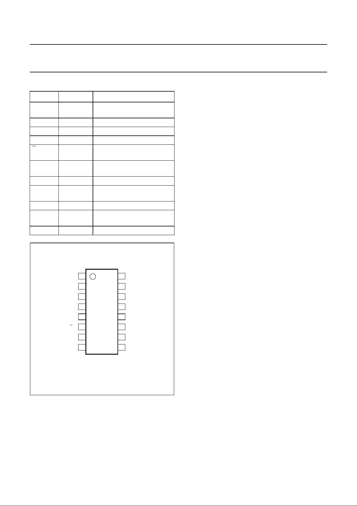
SYMBOL PIN DESCRIPTION
UPOUT 1, 16 output voltage in up mode;
input voltage in down mode
SYNC 2 synchronization clock input
SHDWN 3 shut-down input
LX 4, 5, 12, 13 inductor connection
U/D 6 up-or-down mode selection
input; active LOW for up mode
ILIMH 7 current limiting resistor 1
connection
GND 8, 9 ground
ILIML 10 current limiting resistor 2
connection
ILIMSEL 11 current limiting selection input
PWM 14 PWM-only mode selection
input
FB 15 feedback input
handbook, halfpage
UPOUT
SYNC
SHDWN
LX
LX
U/D
ILIMH
GND
1
2
3
4
TEA1210TS
5
6
7
8
MGR726
16
15
14
13
12
11
10
9
UPOUT
FB
PWM
LX
LX
ILIMSEL
ILIML
GND
Fig.2 Pin configuration.
For all possible applications, the following groups of pins
must be connected together:
• Pins 4, 5, 12 and 13 (pins LX)
• Pins 1 and 16 (pins UPOUT)
• Pins 8 and 9 (pins GND).
FUNCTIONAL DESCRIPTION
Control mechanism
The TEA1210TS DC/DC converter is able to operate in
PFM (discontinuous conduction) or PWM (continuous
conduction) operating mode. All switching actions are
completely determined by a digital control circuit which
usesthe output voltagelevelas itscontrolinput. This novel
digital approachenables the use of a new pulse widthand
frequency modulation scheme, which ensures optimum
power efficiency over the complete operating range of the
converter.
When high output power is requested, the device will
operate in PWM (continuousconduction) operating mode.
This results in minimum AC currents in the circuit
components and hence optimum efficiency, cost and
EMC. In thisoperating mode,the outputvoltage is allowed
to vary between two predefined voltage levels. As long as
the output voltage stays within this so-called window,
switching continues in a fixed pattern. When the output
voltage reaches one of the window borders, the digital
controller immediately reacts by adjusting the pulse width
and inserting a current step in such a way that the output
voltage stays within the window with higher or lower
current capability. This approach enables very fast
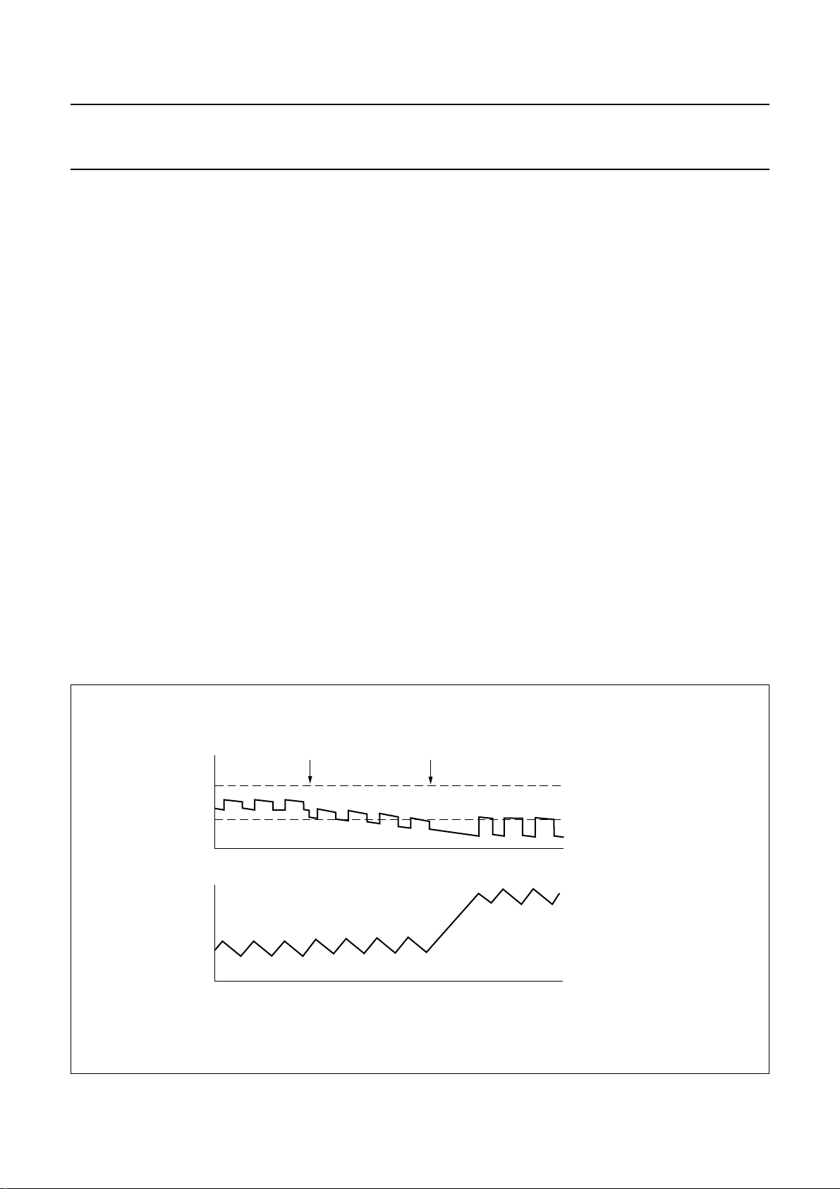
reaction to load variations. Figure 3 shows theconverter’s
response to a sudden load increase. The upper trace
shows the outputvoltage. Theripple ontop ofthe DC level
is a result of the current in the output capacitor, which
changes in sign twice per cycle, times the capacitor’s
internal Equivalent Series Resistance (ESR). After each
ramp-down of the inductor current, i.e. when the ESR
effect increases the output voltage, the converter
determines what to do in the next cycle. As soon as more
load current is taken from the output the output voltage
starts to decay.
When theoutput voltage becomes lower than the low limit
of the window, acorrective action is taken bya ramp-up of
theinductor currentduring a muchlonger time. Asa result,
the DC current levelis increasedand normal PWM control
can continue. The output voltage (including ESR effect) is
again within the predefined window.
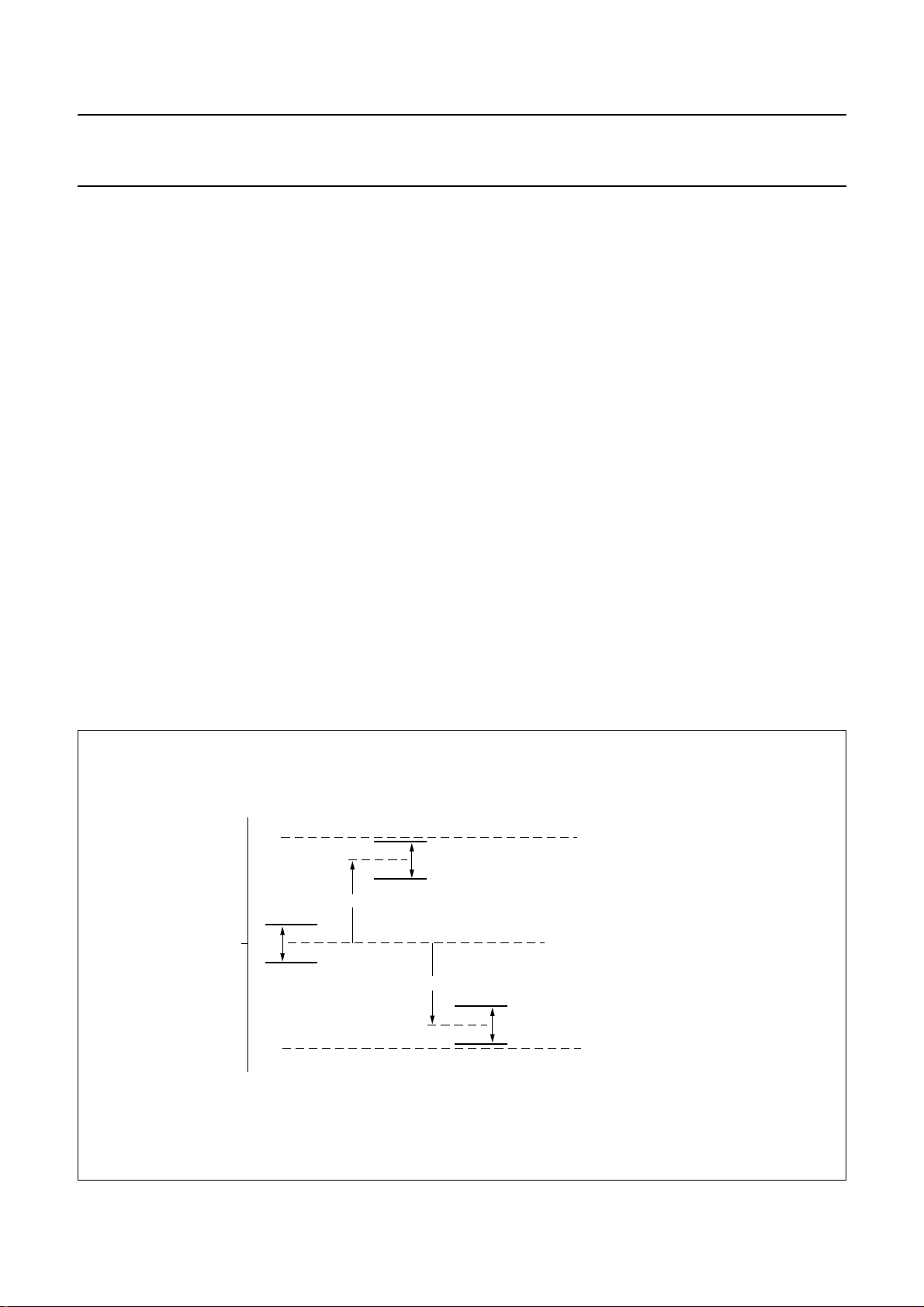
Figure 4 depicts the spread of the output voltage window.
Theabsolutevalue is mostdependenton spread, whilethe
actualwindow sizeis not affected. For onespecific device,
the output voltage will not vary more than 2% typically.
In lowoutput power situations,the TEA1210TS willswitch
overto PFM (discontinuousconduction)operating mode in
case the PWM-only mode is not active.
2000 Nov 28 5
Page 6
Philips Semiconductors Product specification
High efficiency, high current DC/DC converter TEA1210TS
Inthe PFMmode,regulation informationfromearlier PWM
operating modesis used. Thisresults in optimuminductor
peak current levels in the PFM mode, which are slightly
larger than the inductor ripple current in the PWM mode.
As a result,the transitionbetween PFMand PWMmode is
optimum under all circumstances. In the PFM mode,
TEA1210TS regulates the output voltage to the high
window limit shown in Fig.3.
Synchronous rectification
For optimum efficiency over the whole load range,
synchronous rectifiers inside the TEA1210TS ensure that
during the whole second switching phase, all inductor
current will flow through the low-ohmic power MOSFETs.
Special circuitry isincluded whichdetects thatthe inductor
current reaches zero. Following this detection, the digital
controller switches off the power MOSFET and proceeds
regulation.
PWM-only mode
When pin PWM is pulled to HIGH-level in the
upconversion mode, the TEA1210TS will use PWM
regulation independent ofthe loadapplied. Asa result, the
switching frequency does not vary over the whole load
range. Furthermore,the P-type power MOSFET is always
on when the input voltage exceeds the target output
voltage. The internal synchronous rectifier still takes care
that the inductor current does not fall below zero. In this
way, the achieved efficiency is higher than in standard
PWM-controlled converters.
Start-up
Start-up from low input voltage in boost mode is realized
by an independent start-up oscillator, which starts
switching the N-type power MOSFET as soon as the
voltage on pins UPOUT is measured to be sufficiently
high. The switch actions of the start-up oscillator will
increase the output voltage.As soonas theoutput voltage
is high enough for normal regulation, the digital control
system takes over the control of the power MOSFETs.
Undervoltage lockout
As a result of too high load or disconnection of the input
power source, the output voltage can drop so low that
normal regulation cannot be guaranteed. In that case, the
device switches back to start-up mode. If the output
voltage drops down even further, switching is stopped
completely.
Shut-down
When the shut-down input is made HIGH, the converter
disablesboth switchesand power consumptionis reduced
to a few microamperes.
handbook, full pagewidth
load increase
V
o
I
L
start corrective action
Fig.3 Response to load increase.
2000 Nov 28 6
time
time
high window limit
low window limit
MGK925
Page 7
Philips Semiconductors Product specification
High efficiency, high current DC/DC converter TEA1210TS
Power switches
The power switches in the IC are one N-type and one
P-type power MOSFET, having a typical drain-to-source
resistance of 56 and 68 mΩ respectively. The maximum
average current in the power switches is 1.8 A at
T
=60°C.
amb
Temperature protection
When the device operates in the PWM mode, and the die
temperature gets too high(typically 175 °C),the converter
stops operating. It resumes operation when the die
temperature falls below 175 °C again. As a result,
low-frequent cycling between on and off state will occur.
It should be noted that in the event of device temperatures
aroundthe cut-off limit,theapplication differsstronglyfrom
maximum specifications.
Current limiters
If the current inone ofthe powerswitches exceeds its limit
in the PWM mode, the current ramp is stopped
immediately, and the next switching phase is entered.
Current limiting is required to keep power conversion
efficientduring temporary highloads.Furthermore,current
limiting protects the IC against overload conditions,
inductor saturation, etc.
Inthe upconversionmode,the firstcurrentlimit issetby an
external resistor connected between the pins ILIMH
and UPOUT and the second current limit is set by an
external resistor connected between the pins ILIML
and UPOUT. The digital signal on the current limiting
selection input determines which resistor sets the limit
level(pin ILIMSEL = HIGH results inthe use ofpin ILIMH).
The current limiting selection input can accept a digital
signal having a HIGH-level of just 55% of the voltage on
pins UPOUT. The noise margin on this input is increased
by a low-pass filter, having a cutoff frequency of about
50 MHz. However, for stability reasons the level on the
current limiting selection input shall not change within a
period shorter than 20 ms.
In case just one current limit is sufficient, the unused pin
(pin ILIML or ILIMH) must be connected either to the other
pin (pin ILIMH or ILIML), or to pin UPOUT.
In the downconversion mode, the current limiting level is
set internally at a fixed value which is higher than the
current level that most applications require. It should be
regarded as a protection function only. In the
downconversion mode, pins ILIMH and ILIML must be
connected to pin UPOUT.
handbook, full pagewidth
V
out, typ
2%
typical situation
maximum positive spread of V
V
h
V
l
+4%
V
h
2%
V
l
−4%
maximum negative spread of V
Fig.4 Spread of location of output voltage window.
2000 Nov 28 7
fb
upper specification limit
V
h
2%
V
l
lower specification limit
fb
MGR667
Page 8
Philips Semiconductors Product specification
High efficiency, high current DC/DC converter TEA1210TS
External synchronization
If an external high-frequency clock is applied to the
synchronization clock input, the switching frequency in
PWM mode will be exactly that frequency divided by 22.
In PFM mode, the switching frequency is always lower.
The quiescent current of the device increases when an
external clock is applied. In case no external
synchronization is necessary, the synchronization clock
input must be connected to ground level.
voltage drop. In case the converter is in the PFM mode
at high input voltage, the output voltage will equal
VIminus the voltage drop over the external diode.
The current limiting function is not active.
• Downconversion: when the input voltage is lower than
the target output voltage, but higher than 2.9 V, the
P-type power MOSFET will stay conducting resulting in
an output voltage being equal to the input voltage minus
some resistive voltage drop. The current limiting
function remains active.
Behaviour at input voltage exceeding the specified
range
In general, an input voltage exceeding thespecified range
isnot recommendedsince instability mayoccur. Thereare
two exceptions:
• Upconversion:at an input voltage higherthan the target
output voltage, but up to 6 V, the converter will stop
switching. As long as the device is in the PWM mode,
the internal P-type power MOSFET will be conducting
andthe output voltagewillequal VIminussome resistive
LIMITING VALUES
In accordance with the Absolute Maximum Rating System (IEC 60134).
SYMBOL PARAMETER CONDITIONS MIN. MAX. UNIT
V
n
voltage on any pin shut-down mode −0.2 +6.5 V
operating mode −0.2 +5.9 V
T
j
T
amb
T
stg
V
es
junction temperature −40 +150 °C
operating ambient temperature −40 +80 °C
storage temperature −40 +125 °C
electrostatic handling human body model; note 1 −1500 +1500 V
machine model; note 2 −300 +300 V
Notes
1. Equivalent to discharging a 100 pF capacitor through a 1.5 kΩ resistor.
2. Equivalent to discharging a 200 pF capacitor via a 0.75 µH inductor.
THERMAL CHARACTERISTICS
SYMBOL PARAMETER CONDITIONS VALUE UNIT
R
th(j-a)
thermal resistance from junction to ambient in free air 140 K/W
QUALITY SPECIFICATION
Product lifetime is fully guaranteed over 2000 hours ofoperation at an ambient temperatureof 60 °C with a continuously
repeating current profile on pins LX of 4 A during 577 µs followed by 1 A during 4.0 ms. All remaining quality
specifications are in accordance with
“SNW-FQ-611 part E”
.
2000 Nov 28 8
Page 9
Philips Semiconductors Product specification
High efficiency, high current DC/DC converter TEA1210TS
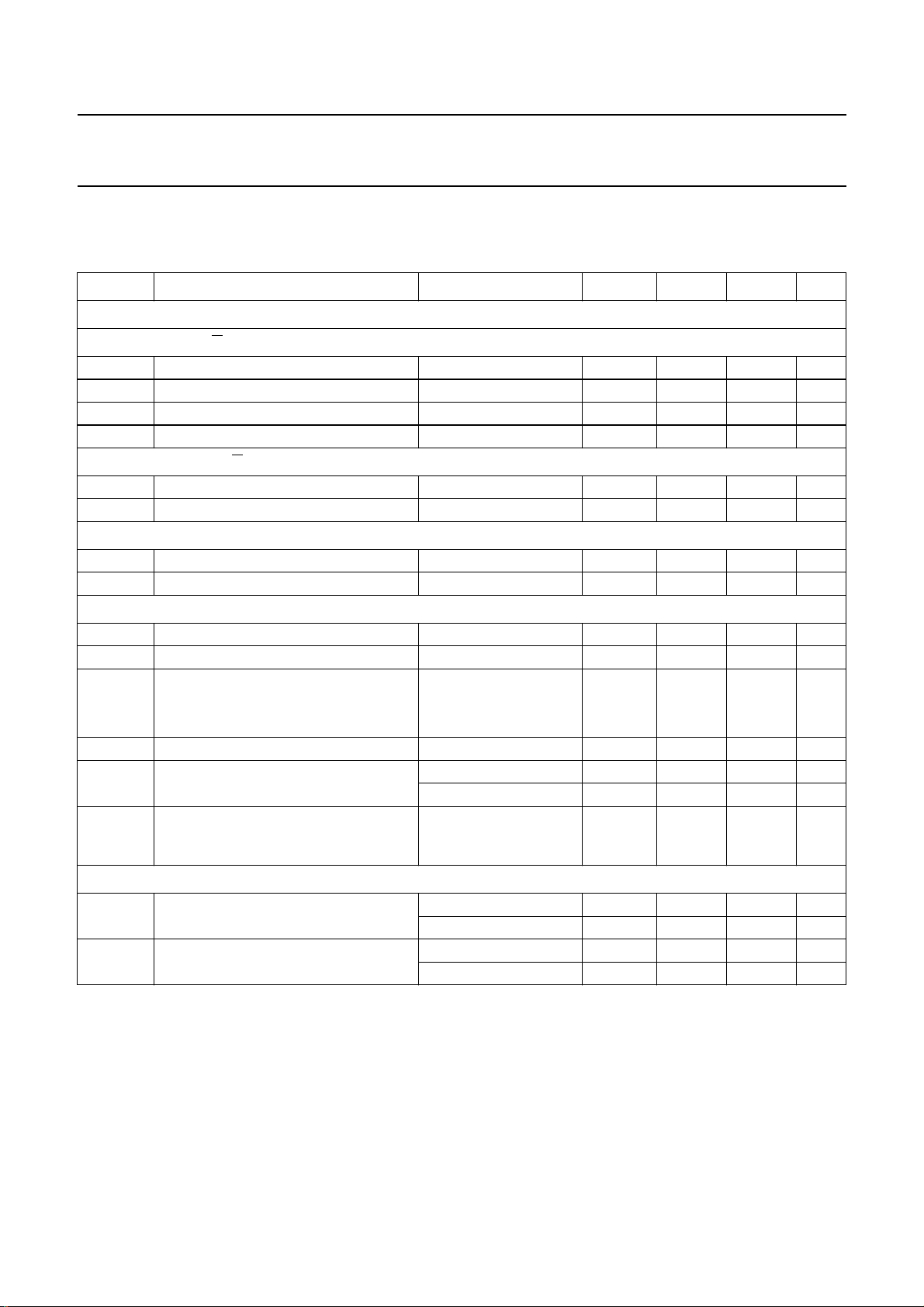
CHARACTERISTICS
T
= −40 to +80 °C; all voltages are measured with respect to ground; positive currents flow into theIC; unless
amb
otherwise specified.
SYMBOL PARAMETER CONDITIONS MIN. TYP. MAX. UNIT
Voltage levels
PCONVERSION; PIN U/D = LOW
U
V
I
V
O
V
I(start)
V
I(uvlo)
OWNCONVERSION; PIN U/D = HIGH
D
V
I
V
O
input voltage V
output voltage 2.90 − 5.50 V
start-up input voltage IL< 200 mA 1.20 1.60 1.85 V
undervoltage lockout input voltage note 1 1.50 2.10 2.70 V
input voltage note 2 2.90 − 5.50 V
output voltage 1.30 − 5.50 V
GENERAL
V
∆V
fb
window
feedback input voltage 1.20 1.25 1.30 V
output voltage window PWM mode 1.5 2.0 3.0 %
Current levels
I
q
I
shdwn
∆I
lim(up)
I
lim(down)
I
LX
quiescent current on pins LX up mode; note 3 100 125 150 µA
current in shut-down mode − 210µA
current limit deviation in up mode note 4
current limit in down mode − 4.8 − A
maximum continuous current on
pins LX
I
UPOUT
maximum continuous current on
pins UPOUT
Power MOSFETs
R
DSon(N)
drain-to-source on-state resistance
NFET
R
DSon(P)
drain-to-source on-state resistance
PFET
I(start)
I
set to 0.4 A −20 − +20 %
lim(up)
I
set to 2.0 A −12 − +12 %
lim(up)
T
=80°C −−1.5 A
amb
=60°C −−1.8 A
T
amb
up mode;
−−0.65 A
VI= 1.8 V; VO= 3.6 V;
T
=80°C
amb
Tj=27°C − 56 63 mΩ
T
= 100 °C − 75 84 mΩ
j
Tj=27°C − 68 77 mΩ
T
= 100 °C − 92 104 mΩ
j
− 5.50 V
2000 Nov 28 9
Page 10

Philips Semiconductors Product specification
High efficiency, high current DC/DC converter TEA1210TS
SYMBOL PARAMETER CONDITIONS MIN. TYP. MAX. UNIT
Efficiency
η1 efficiency upconversion T
η2 efficiency upconversion T
η3 efficiency upconversion T
η4 efficiency upconversion T
Timing
f
sw
f
sync
t
start
t
res
switching frequency PWM mode 480 600 720 kHz
synchronization clock input frequency 9 13 20 MHz
start-up time note 7 − 6 − ms
response time from standby to P
Temperature
T
amb
T
max
operating ambient temperature −40 +25 +80 °C
internal cut-off temperature 150 175 200 °C
=20°C;
amb
VI= 1.8 V; VO= 3.6 V;
note 5
I
= 1 mA 80 82 − %
L
I
= 4 mA 84 86 − %
L
= 100 mA 89 91 − %
I
L
I
= 500 mA 89 91 − %
L
= 1.5 A; note 6 73 75 − %
I
L
=80°C;
amb
VI= 1.8 V; VO= 3.6 V;
note 5
I
= 1 mA 78 80 − %
L
= 4 mA 82 84 − %
I
L
I
= 100 mA 87 89 − %
L
I
= 500 mA 88 90 − %
L
I
= 1.5 A; note 6 67 72 − %
L
=20°C;
amb
VI= 2.4 V; VO= 3.6 V;
note 5
= 1 mA 83 86 − %
I
L
I
= 4 mA 87 90 − %
L
I
= 100 mA 90 93 − %
L
= 500 mA 92 94 − %
I
L
I
= 1.5 A; note 6 84 86 − %
L
=80°C;
amb
VI= 2.4 V; VO= 3.6 V;
note 5
I
= 1 mA 81 83 − %
L
= 4 mA 85 87 − %
I
L
I
= 100 mA 88 90 − %
L
= 500 mA 91 93 − %
I
L
I
= 1.5 A; note 6 82 85 − %
L
o(max)
− 25 −µs
2000 Nov 28 10
Page 11

Philips Semiconductors Product specification
High efficiency, high current DC/DC converter TEA1210TS
SYMBOL PARAMETER CONDITIONS MIN. TYP. MAX. UNIT
Digital levels
V
lL
LOW-level input voltage
on pins SHDWN, ILIMSEL, U/D
and SYNC
V
IH
HIGH-level input voltage
on pins
U/D and PWM note 8 V1− 0.4 − V1+ 0.3 V
on pins SYNC and SHDWN note 8 0.55V
on pin ILIMSEL notes 8 and 9 0.55V
Notes
1. The undervoltage lockout voltage shows wide specification limits since it decreases at increasing temperature.
When the temperature increases, the minimum supply voltage of the digital control part of the IC decreases and
therefore the correct operation of this function is guaranteed over the whole temperature range.
2. When VI is lower than the target output voltage but higher than 2.9 V, the P-type power MOSFET will remain
conducting (100% duty cycle), resulting in VO following VI.
3. The quiescent current is specified as the input current in the upconversion configuration at VI= 2.40 V and
VO= 3.60 V, using L1 = 6.8 µH, R1 = 178 kΩ and R2 = 93.1 kΩ (see Fig.5).
4. The current limit is defined by the external current limiting resistors, see Section “Current limiting resistors”.
R
= 996 Ω results in a typical current limit of 400 mA and R
limx
The spread of the current limit decreases with increasing the I
= 178 Ω results in a typical current limit of 2.0 A.
limx
setpoint.
lim
5. The specified efficiency is valid when using an output capacitor having an ESR of 0.04 Ω and an inductor having an
inductance of 6.8 µH, an ESR of 0.04 Ω, and a sufficient saturation current level. The current limit is assumed to be
set at 4.0 A. In the PWM-only mode, the efficiency at IL= 1 mA and IL= 4 mA is lower than the values specified.
6. The specified efficiency at IL= 1.5 A is only valid if the average input current does not exceed the maximum
value of ILX. In most practical applications, this means that the load current is not continuous.
7. The specified start-up time is the time between the connection of a 2.40 V input voltage source and the moment the
output reaches 3.60 V. The output capacitance equals 2000 µF, the inductance equals 6.8 µH, no load is present.
8. V1 is the voltage on the pins UPOUT. If the applied HIGH-level voltage is less than V1− 1 V, the quiescent current
of the device will increase.
9. Maximum additionalsupply currenton the pins UPOUT is 50 µAin case the voltage V1= 5.0 V and the inputvoltage
on pin ILIMSEL is 2.2 V.
0 − 0.4 V
− V1+ 0.3 V
1
− V1+ 0.3 V
1
2000 Nov 28 11
Page 12
Philips Semiconductors Product specification
High efficiency, high current DC/DC converter TEA1210TS
APPLICATION INFORMATION
handbook, full pagewidth
V
I
C1
D1
UPOUT
1, 16
L1
LX
4, 5,
12, 13
623 7
8, 9
GND
U/D
SYNC SHDWN
TEA1210TS
14
PWM11ILIMSEL ILIMH
R1
FB
15
10
ILIML
R
limh
R
liml
R2
C2
C3
MGR727
V
O
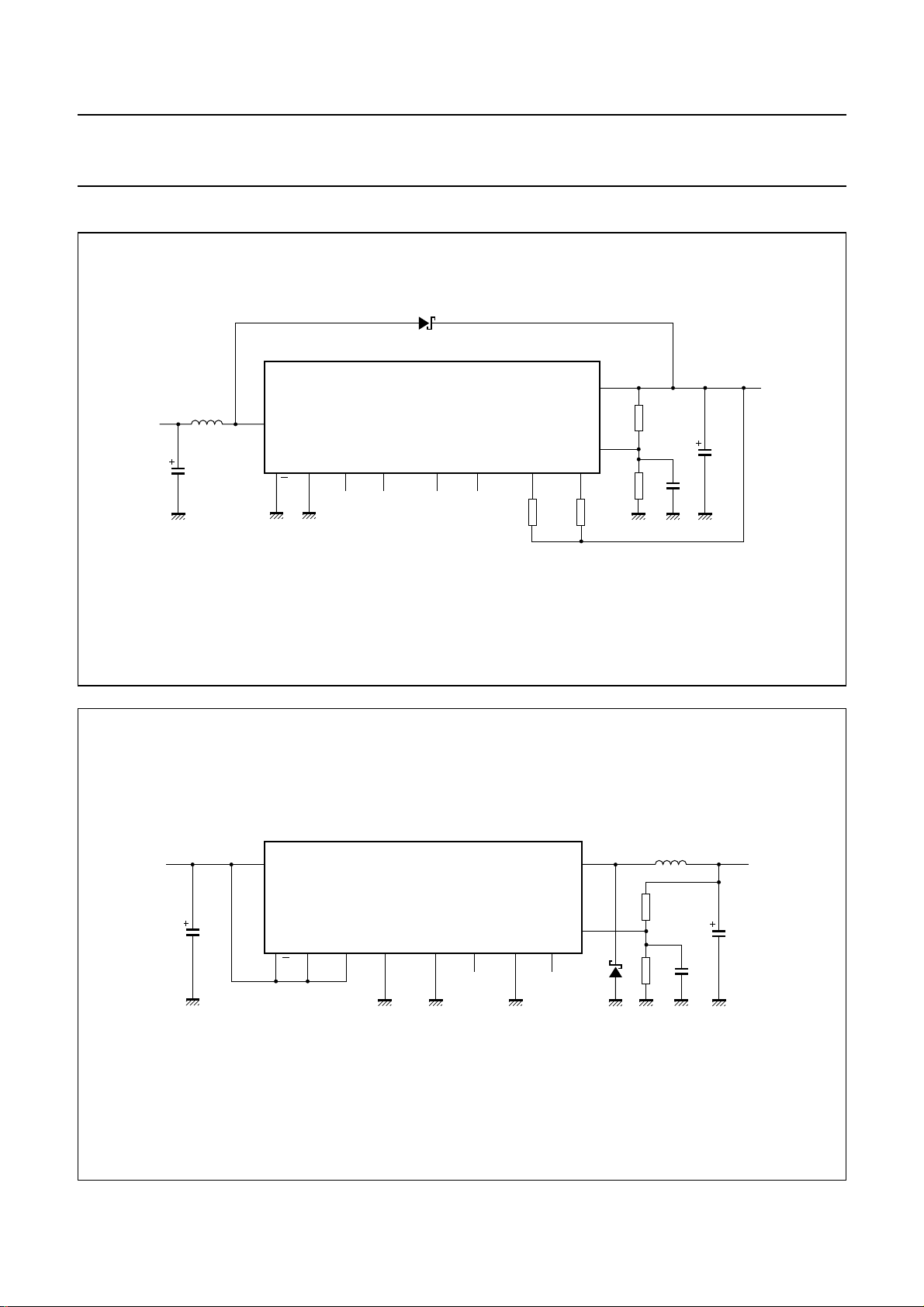
Fig.5 Complete application for upconversion.
handbook, full pagewidth
V
I
UPOUT
1, 16
TEA1210TS
C1
106 2 8, 9 3
7
ILIMH
11
ILIMSEL
14
PWM SHDWNILIML
Fig.6 Complete application for downconversion.
2000 Nov 28 12
D1
R1
R2
L1
C3
C2
MGR728
V
O
LX
4, 5,
12, 13
FB
15
GNDU/D SYNC
Page 13

Philips Semiconductors Product specification
High efficiency, high current DC/DC converter TEA1210TS
External component selection
INDUCTOR L1
The performance of the TEA1210TS is not very sensitive
to inductance value. Best efficiency performance over a
wide load current range is achieved by using an
inductanceof 6.8 µH andasaturationcurrent levelof 3.0 A
at least. In case the maximum output current is lower,
other inductors are also suitable such as the
TDK SLF7032 range.
DIODE D1
The Schottky diode is only used a short time during
takeover from N-type power MOSFET and P-type power
MOSFET and vice versa. Therefore, a medium-power
diode such as Philips PRLL5819 is sufficient in most
applications.
INPUT CAPACITOR C1
The valueof capacitor C1strongly depends on the type of
input source. In general, a 100 µF tantalum capacitor will
do, or a 10 µF ceramic capacitor featuring very low series
resistance (ESR value).
OUTPUT CAPACITOR C2
CURRENT LIMITING RESISTORS
The maximum instantaneous current in upconversion
mode is set byone of the external resistorsR
limh
and R
liml
The preferred type is SMD, 1% accurate.
The digital level on pin ILIMSEL defines which one of the
resistors is used to determine the current limiting level.
The functionality of both settings is identical.
In case one current limit is enough, the unused pin
(pin ILIML or ILIMH) must be connected either to the other
pin (pin ILIMH or ILIML), or to pin UPOUT.
The values of the current limiting resistors can be derived
from the simplified formula:
R
=
limh
=
R
liml
346
----------------------------------I
lim up()
----------------------------------I
lim up()
0.05–
346
0.05–
, active when ILIMSEL = HIGH
, active when ILIMSEL = LOW
The average inductor current during limited current
operation also depends on the inductance value and the
resistive losses in all components in the power path.
Ensure that both current limiting levels do not exceed the
saturation current of the inductor.
.
The value and type of capacitor C2 depend on the
maximum output current and the ripple voltage which is
allowed in the application. Low-ESR tantalum capacitors
show best results. The most important specification of
capacitorC2 is itsESRvalue, which mainlydeterminesthe
output voltage ripple.
FEEDBACK CAPACITOR C3
Capacitor C3 preventsthe feedbackvoltage frompolluting
by switching noise. A ceramic type of capacitor having a
maximum value of 33 pF is recommended.
FEEDBACK RESISTORS R1 AND R2
The output voltage is determined by the resistors
R1 and R2. The following conditions apply:
• Use 1% accurate SMD type resistors
• Resistors R1 and R2 should have a maximum value of
50 kΩ when connected in parallel. A higher value will
result in inaccurate operation.
Under these conditions, the output voltage can be
R1
calculated by the formula:
V
O
1.25 1
×=
+
------- R2
2000 Nov 28 13
Page 14
Philips Semiconductors Product specification
High efficiency, high current DC/DC converter TEA1210TS
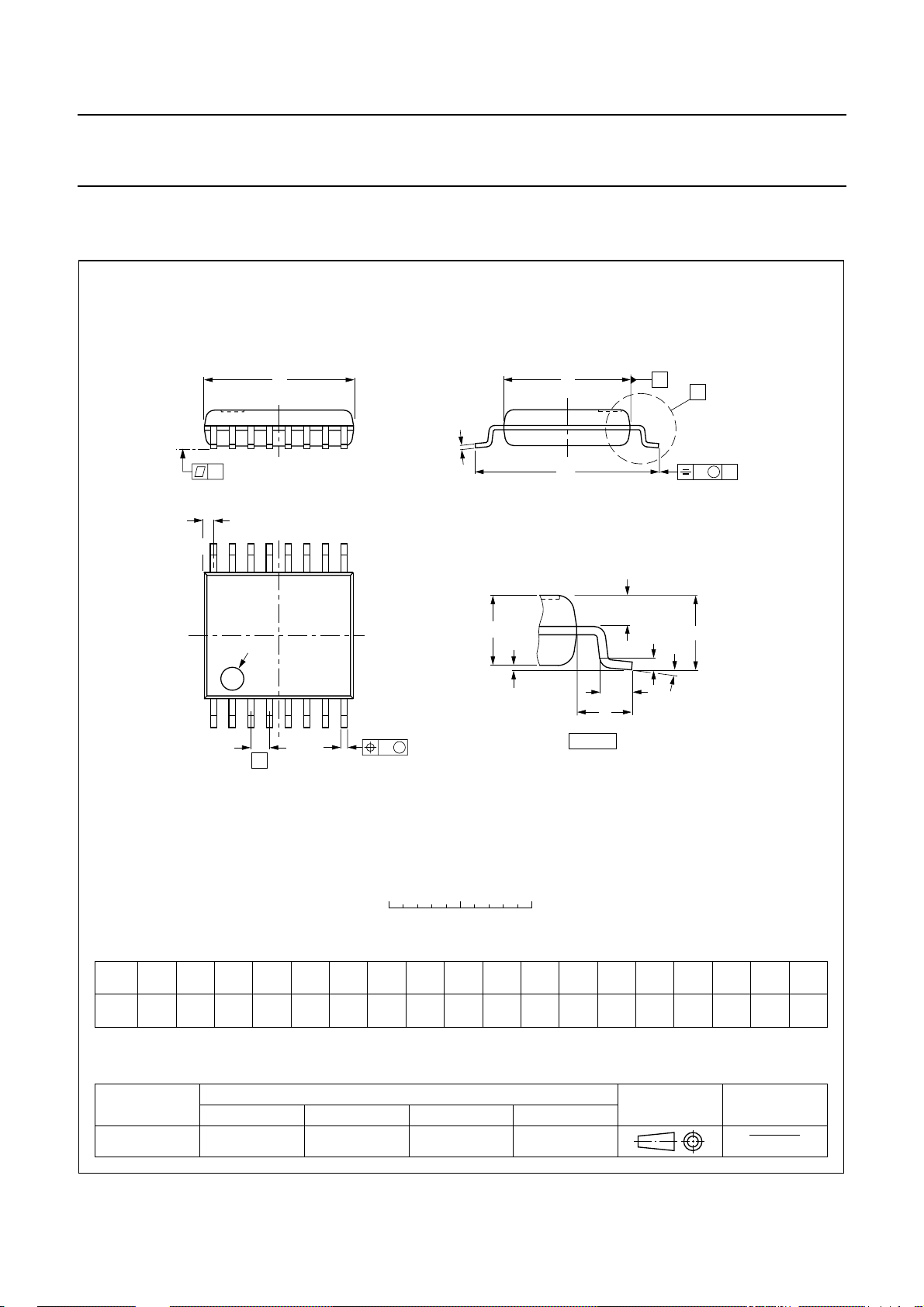
PACKAGE OUTLINE
SSOP16: plastic shrink small outline package; 16 leads; body width 4.4 mm
SOT369-1
D
c
y
Z
16
pin 1 index
9
18
w M
b
e
p
E
H
E
A
2
A
1
L
detail X
A
X
v M
A
Q
(A )
L
p
A
3
θ
0 2.5 5 mm
scale
DIMENSIONS (mm are the original dimensions)
UNIT A1A
Note
1. Plastic or metal protrusions of 0.20 mm maximum per side are not included.
A
max.
1.5
0.15
0.00
mm
OUTLINE
VERSION
SOT369-1 MO-152
A3b
2
1.4
0.25
1.2
IEC JEDEC EIAJ
p
0.32
0.20
0.25
0.13
(1)E(1)
cD
5.30
5.10
REFERENCES
4.5
4.3
0.65
2000 Nov 28 14
eHELLpQZywv θ
1.0
0.75
0.45
0.65
0.45
PROJECTION
0.130.2 0.1
EUROPEAN
6.6
6.2
(1)
0.48
0.18
ISSUE DATE
95-02-04
99-12-27
o
10
o
0
Page 15

Philips Semiconductors Product specification
High efficiency, high current DC/DC converter TEA1210TS
SOLDERING
Introduction to soldering surface mount packages
Thistext gives averybrief insighttoa complex technology.
A more in-depth account of soldering ICs can be found in
our
“Data Handbook IC26; Integrated Circuit Packages”
(document order number 9398 652 90011).
There is no soldering method that is ideal for all surface
mount IC packages. Wave soldering can still be used for
certainsurface mount ICs,butit is notsuitablefor fine pitch
SMDs. In these situations reflow soldering is
recommended.
Reflow soldering
Reflow soldering requires solder paste (a suspension of
fine solder particles, flux and binding agent) to be applied
tothe printed-circuitboardby screenprinting,stencilling or
pressure-syringe dispensing before package placement.
Several methods exist for reflowing; for example,
convection or convection/infrared heating in a conveyor
type oven. Throughput times (preheating, soldering and
cooling) vary between 100 and 200 seconds depending
on heating method.
Typical reflow peak temperatures range from
215 to 250 °C. The top-surface temperature of the
packages should preferable be kept below 220 °C for
thick/large packages, and below 235 °C for small/thin
packages.
Wave soldering
Conventional single wave soldering is not recommended
forsurface mount devices(SMDs)or printed-circuit boards
with a high component density, as solder bridging and
non-wetting can present major problems.
To overcome these problems the double-wave soldering
method was specifically developed.
If wave soldering is used the following conditions must be
observed for optimal results:
• Use a double-wave soldering method comprising a
turbulent wavewith high upwardpressure followed bya
smooth laminar wave.
• For packages with leads on two sides and a pitch (e):
– larger than or equal to 1.27 mm, the footprint
longitudinal axis is preferred to be parallel to the
transport direction of the printed-circuit board;
– smaller than 1.27 mm, the footprint longitudinal axis
must be parallel to the transport direction of the
printed-circuit board.
The footprint must incorporate solder thieves at the
downstream end.
• Forpackageswith leads onfoursides, the footprintmust
be placedat a 45° angle to the transport direction of the
printed-circuit board. The footprint must incorporate
solder thieves downstream and at the side corners.
During placement and before soldering, the package must
be fixed with a droplet of adhesive. The adhesive can be
applied by screen printing, pin transfer or syringe
dispensing. The package can be soldered after the
adhesive is cured.
Typical dwell time is 4 seconds at 250 °C.
A mildly-activated flux will eliminate the need for removal
of corrosive residues in most applications.
Manual soldering
Fix the component by first soldering two
diagonally-opposite end leads. Use a low voltage (24 V or
less) soldering iron applied to the flat part of the lead.
Contact time must be limited to 10 seconds at up to
300 °C.
2000 Nov 28 15
When using a dedicated tool, all other leads can be
soldered in one operation within 2 to 5 seconds between
270 and 320 °C.
Page 16

Philips Semiconductors Product specification
High efficiency, high current DC/DC converter TEA1210TS
Suitability of surface mount IC packages for wave and reflow soldering methods
PACKAGE
WAVE REFLOW
(1)
BGA, HBGA, LFBGA, SQFP, TFBGA not suitable suitable
SOLDERING METHOD
HBCC, HLQFP, HSQFP, HSOP, HTQFP, HTSSOP, HVQFN, SMS not suitable
(3)
PLCC
, SO, SOJ suitable suitable
LQFP, QFP, TQFP not recommended
SSOP, TSSOP, VSO not recommended
(2)
(3)(4)
(5)
suitable
suitable
suitable
Notes
1. All surface mount (SMD) packages are moisture sensitive. Depending upon the moisture content, the maximum
temperature (with respect to time) and body size of the package, there is a risk that internal or external package
cracks may occur due to vaporization of the moisture in them (the so called popcorn effect). For details, refer to the
Drypack information in the
“Data Handbook IC26; Integrated Circuit Packages; Section: Packing Methods”
.
2. These packages are not suitable for wave soldering as a solder joint between the printed-circuit board and heatsink
(at bottom version) can not be achieved, and as solder may stick to the heatsink (on top version).
3. If wave soldering is considered, then the package must be placed at a 45° angle to the solder wave direction.
The package footprint must incorporate solder thieves downstream and at the side corners.
4. Wave soldering is only suitable for LQFP, TQFP and QFP packages with a pitch (e) equal to or larger than 0.8 mm;
it is definitely not suitable for packages with a pitch (e) equal to or smaller than 0.65 mm.
5. Wave soldering is onlysuitable for SSOP and TSSOPpackages with a pitch (e)equal to or larger than0.65 mm; it is
definitely not suitable for packages with a pitch (e) equal to or smaller than 0.5 mm.
2000 Nov 28 16
Page 17

Philips Semiconductors Product specification
High efficiency, high current DC/DC converter TEA1210TS
DATA SHEET STATUS
DATA SHEET STATUS
Objective specification Development This data sheet contains the design target or goal specifications for
Preliminary specification Qualification This data sheet contains preliminary data, and supplementary data will be
Product specification Production This data sheet contains final specifications. Philips Semiconductors
Note
1. Please consult the most recently issued data sheet before initiating or completing a design.
DEFINITIONS
Short-form specification The data in a short-form
specification is extracted from a full data sheet with the
same type number and title. For detailed information see
the relevant data sheet or data handbook.
Limiting values definition Limiting valuesgiven are in
accordance with the Absolute Maximum Rating System
(IEC 60134). Stress above one or more of the limiting
values may cause permanent damage to the device.
These are stress ratings only and operation of the device
atthese or atany other conditionsabovethose giveninthe
Characteristics sectionsof the specification is not implied.
Exposure to limiting values for extended periods may
affect device reliability.
Application information Applications that are
described herein for any of these products are for
illustrative purposes only. Philips Semiconductors make
norepresentation or warrantythatsuchapplications will be
suitable for the specified use without further testing or
modification.
PRODUCT
STATUS
DEFINITIONS
product development. Specification may change in any manner without
notice.
published at a later date. Philips Semiconductors reserves the right to
make changes at any time without notice in order to improve design and
supply the best possible product.
reserves the right to make changes at any time without notice in order to
improve design and supply the best possible product.
DISCLAIMERS
Life support applications These products are not
designed for use in life support appliances, devices, or
systems where malfunction of these products can
reasonably be expectedto resultin personalinjury. Philips
Semiconductorscustomers using orselling theseproducts
for use in such applications do so at their own risk and
agree to fully indemnify Philips Semiconductors for any
damages resulting from such application.
Right to make changes Philips Semiconductors
reserves the right to make changes, without notice, in the
products, including circuits, standard cells, and/or
software, described or contained herein in order to
improve design and/or performance. Philips
Semiconductors assumes no responsibility or liability for
theuse of anyofthese products, conveysnolicence or title
under any patent, copyright, or mask work right to these
products,and makesnorepresentations or warrantiesthat
these products are free from patent, copyright, or mask
work right infringement, unless otherwise specified.
(1)
2000 Nov 28 17
Page 18

Philips Semiconductors Product specification
High efficiency, high current DC/DC converter TEA1210TS
NOTES
2000 Nov 28 18
Page 19

Philips Semiconductors Product specification
High efficiency, high current DC/DC converter TEA1210TS
NOTES
2000 Nov 28 19
Page 20

Philips Semiconductors – a w orldwide compan y
Argentina: see South America
Australia: 3 Figtree Drive, HOMEBUSH, NSW 2140,
Tel. +61 2 9704 8141, Fax. +61 2 9704 8139
Austria: Computerstr. 6, A-1101 WIEN, P.O. Box 213,
Tel. +43 1 60 101 1248, Fax. +43 1 60 101 1210
Belarus: Hotel Minsk Business Center, Bld. 3, r. 1211, Volodarski Str. 6,
220050 MINSK, Tel. +375 172 20 0733, Fax. +375 172 20 0773
Belgium: see The Netherlands
Brazil: seeSouth America
Bulgaria: Philips Bulgaria Ltd., Energoproject, 15thfloor,
51 James Bourchier Blvd., 1407 SOFIA,
Tel. +359 2 68 9211, Fax. +359 2 68 9102
Canada: PHILIPS SEMICONDUCTORS/COMPONENTS,
Tel. +1 800 234 7381, Fax. +1 800 943 0087
China/Hong Kong: 501 Hong Kong Industrial Technology Centre,
72 Tat Chee Avenue, Kowloon Tong, HONG KONG,
Tel. +852 2319 7888, Fax. +852 2319 7700
Colombia: see South America
Czech Republic: see Austria
Denmark: Sydhavnsgade 23, 1780 COPENHAGEN V,
Tel. +45 33 29 3333, Fax. +45 33 29 3905
Finland: Sinikalliontie 3, FIN-02630 ESPOO,
Tel. +358 9 615 800, Fax. +358 9 6158 0920
France: 51 Rue Carnot, BP317, 92156 SURESNES Cedex,
Tel. +33 1 4099 6161, Fax. +33 1 4099 6427
Germany: Hammerbrookstraße 69, D-20097 HAMBURG,
Tel. +49 40 2353 60, Fax. +49 40 2353 6300
Hungary: seeAustria
India: Philips INDIA Ltd, Band Box Building, 2nd floor,
254-D, Dr. Annie Besant Road, Worli, MUMBAI 400 025,
Tel. +91 22 493 8541, Fax. +91 22 493 0966
Indonesia: PT Philips Development Corporation, Semiconductors Division,
Gedung Philips, Jl. Buncit Raya Kav.99-100, JAKARTA 12510,
Tel. +62 21 794 0040 ext. 2501, Fax. +62 21 794 0080
Ireland: Newstead, Clonskeagh, DUBLIN 14,
Tel. +353 1 7640 000, Fax. +353 1 7640 200
Israel: RAPAC Electronics, 7 Kehilat Saloniki St, PO Box 18053,
TEL AVIV 61180, Tel. +972 3 645 0444, Fax. +972 3 649 1007
Italy: PHILIPS SEMICONDUCTORS, Via Casati, 23 - 20052 MONZA(MI),
Tel. +39 039 203 6838, Fax +39 039 203 6800
Japan: Philips Bldg 13-37, Kohnan 2-chome, Minato-ku,
TOKYO 108-8507, Tel. +81 3 3740 5130, Fax. +81 3 3740 5057
Korea: Philips House, 260-199 Itaewon-dong, Yongsan-ku, SEOUL,
Tel. +82 2 709 1412, Fax. +82 2 709 1415
Malaysia: No. 76 Jalan Universiti, 46200 PETALING JAYA, SELANGOR,
Tel. +60 3 750 5214, Fax. +60 3 757 4880
Mexico: 5900 Gateway East, Suite 200, EL PASO, TEXAS 79905,
Tel. +9-5 800 234 7381, Fax +9-5 800 943 0087
Middle East: see Italy
Netherlands: Postbus 90050, 5600 PB EINDHOVEN, Bldg. VB,
Tel. +31 40 27 82785, Fax. +31 40 27 88399
New Zealand: 2 Wagener Place, C.P.O. Box 1041, AUCKLAND,
Tel. +64 9 849 4160, Fax. +64 9 849 7811
Norway: Box 1, Manglerud 0612, OSLO,
Tel. +47 22 74 8000, Fax. +47 22 74 8341
Pakistan: see Singapore
Philippines: Philips Semiconductors Philippines Inc.,
106 Valero St. Salcedo Village, P.O. Box 2108 MCC, MAKATI,
Metro MANILA, Tel. +63 2 816 6380, Fax. +63 2 817 3474
Poland: Al.Jerozolimskie 195 B, 02-222 WARSAW,
Tel. +48 22 5710 000, Fax. +48 22 5710 001
Portugal: see Spain
Romania: see Italy
Russia: Philips Russia, Ul. Usatcheva 35A, 119048 MOSCOW,
Tel. +7 095 755 6918, Fax. +7 095 755 6919
Singapore: Lorong 1, Toa Payoh, SINGAPORE 319762,
Tel. +65 350 2538, Fax. +65 251 6500
Slovakia: see Austria
Slovenia: see Italy
South Africa: S.A. PHILIPS Pty Ltd., 195-215 Main Road Martindale,
2092 JOHANNESBURG, P.O. Box 58088 Newville 2114,
Tel. +27 11 471 5401, Fax. +27 11 471 5398
South America: Al. Vicente Pinzon, 173, 6th floor,
04547-130 SÃO PAULO, SP, Brazil,
Tel. +55 11 821 2333, Fax. +55 11 821 2382
Spain: Balmes 22, 08007 BARCELONA,
Tel. +34 93 301 6312, Fax. +34 93 301 4107
Sweden: Kottbygatan 7, Akalla, S-16485 STOCKHOLM,
Tel. +46 8 5985 2000, Fax. +46 8 5985 2745
Switzerland: Allmendstrasse 140, CH-8027 ZÜRICH,
Tel. +41 1 488 2741 Fax. +41 1 488 3263
Taiwan: Philips Semiconductors, 5F, No. 96, Chien Kuo N. Rd., Sec. 1,
TAIPEI, Taiwan Tel. +886 2 2134 2451, Fax. +886 2 2134 2874
Thailand: PHILIPS ELECTRONICS (THAILAND) Ltd.,
60/14 MOO 11, Bangna Trad Road KM. 3, Bagna, BANGKOK 10260,
Tel. +66 2 361 7910, Fax. +66 2 398 3447
Turkey: Yukari Dudullu, Org. San. Blg., 2.Cad. Nr. 28 81260 Umraniye,
ISTANBUL, Tel. +90 216 522 1500, Fax. +90 216 522 1813
Ukraine: PHILIPS UKRAINE, 4 Patrice Lumumba str., Building B, Floor 7,
252042 KIEV, Tel. +380 44 264 2776, Fax. +380 44 268 0461
United Kingdom: Philips Semiconductors Ltd., 276 Bath Road, Hayes,
MIDDLESEX UB3 5BX, Tel. +44 208 730 5000, Fax. +44 208 754 8421
United States: 811 East Arques Avenue, SUNNYVALE, CA 94088-3409,
Tel. +1 800 234 7381, Fax. +1 800 943 0087
Uruguay: see South America
Vietnam: see Singapore
Yugoslavia: PHILIPS, Trg N. Pasica 5/v, 11000 BEOGRAD,
Tel. +381 11 3341 299, Fax.+381 11 3342 553
For all other countries apply to: Philips Semiconductors,
Marketing Communications, Building BE-p, P.O. Box 218, 5600 MD EINDHOVEN,
The Netherlands, Fax. +31 40 27 24825
© Philips Electronics N.V. SCA
All rights are reserved. Reproduction in whole or in part is prohibited without the prior written consent of the copyright owner.
The information presented in this document does not form part of any quotation or contract, is believed to be accurate and reliable and may be changed
without notice. No liability will be accepted by the publisher for any consequence of its use. Publication thereof does not convey nor imply any license
under patent- or other industrial or intellectual property rights.
2000
Internet: http://www.semiconductors.philips.com
70
Printed in The Netherlands 403502/50/02/pp20 Date of release: 2000 Nov 28 Document order number: 9397 750 07782
 Loading...