

Page 1

INTEGRATED CIRCUITS
DATA SH EET
TDA9817; TDA9818
Single/multistandard VIF/SIF-PLL
and FM-PLL/AM demodulators
Preliminary specification
File under Integrated Circuits, IC02
1997 May 12
Page 2
Philips Semiconductors Preliminary specification
Single/multistandard VIF/SIF-PLL and
FM-PLL/AM demodulators
FEATURES
• 5 V supply voltage
• Applicable for IFs (Intermediate Frequencies) of
38.9 MHz, 45.75 MHz and 58.75 MHz
• Gain controlled wide band Video IF (VIF)-amplifier
(AC-coupled)
• True synchronous demodulation with active carrier
regeneration (very linear demodulation, good
intermodulation figures, reduced harmonics,
excellent pulse response)
• Robustness for over-modulation better than 105% due
to gated phase detector at L/L accent standard and
PLL-bandwidth control at negative modulated standards
• VCO (Voltage Controlled Oscillator) frequency
switchable between L and L accent (alignment external)
picture carrier frequency
• VIF AGC (Automatic Gain Control) detector for gain
control, operating as peak sync detector for B/G, peak
white detector for L; signal controlled reaction time for L
• Tuner AGC with adjustable TakeOver Point (TOP)
• AFC (Automatic Frequency Control) detector without
extra reference circuit
TDA9817; TDA9818
• AC-coupled limiter amplifier for sound intercarrier signal
• Alignment-free FM PLL (Phase Locked Loop)
demodulator with high linearity
• SIF (Sound IF) input for single reference QSS (Quasi
Split Sound) mode (PLL controlled); SIF AGC detector
for gain controlled SIF amplifier; single reference QSS
mixer able to operate in high performance single
reference QSS mode and in intercarrier mode
• AM demodulator without extra reference circuit
• Stabilizer circuit for ripple rejection and to achieve
constant output signals
• ESD (Electrostatic Discharge) protection for all pins.
GENERAL DESCRIPTION
The TDA9817 is an integrated circuit for single standard
vision IF signal processing and FM demodulation.
The TDA9818 is an integrated circuit for multistandard
vision IF signal processing, sound AM and FM
demodulation.
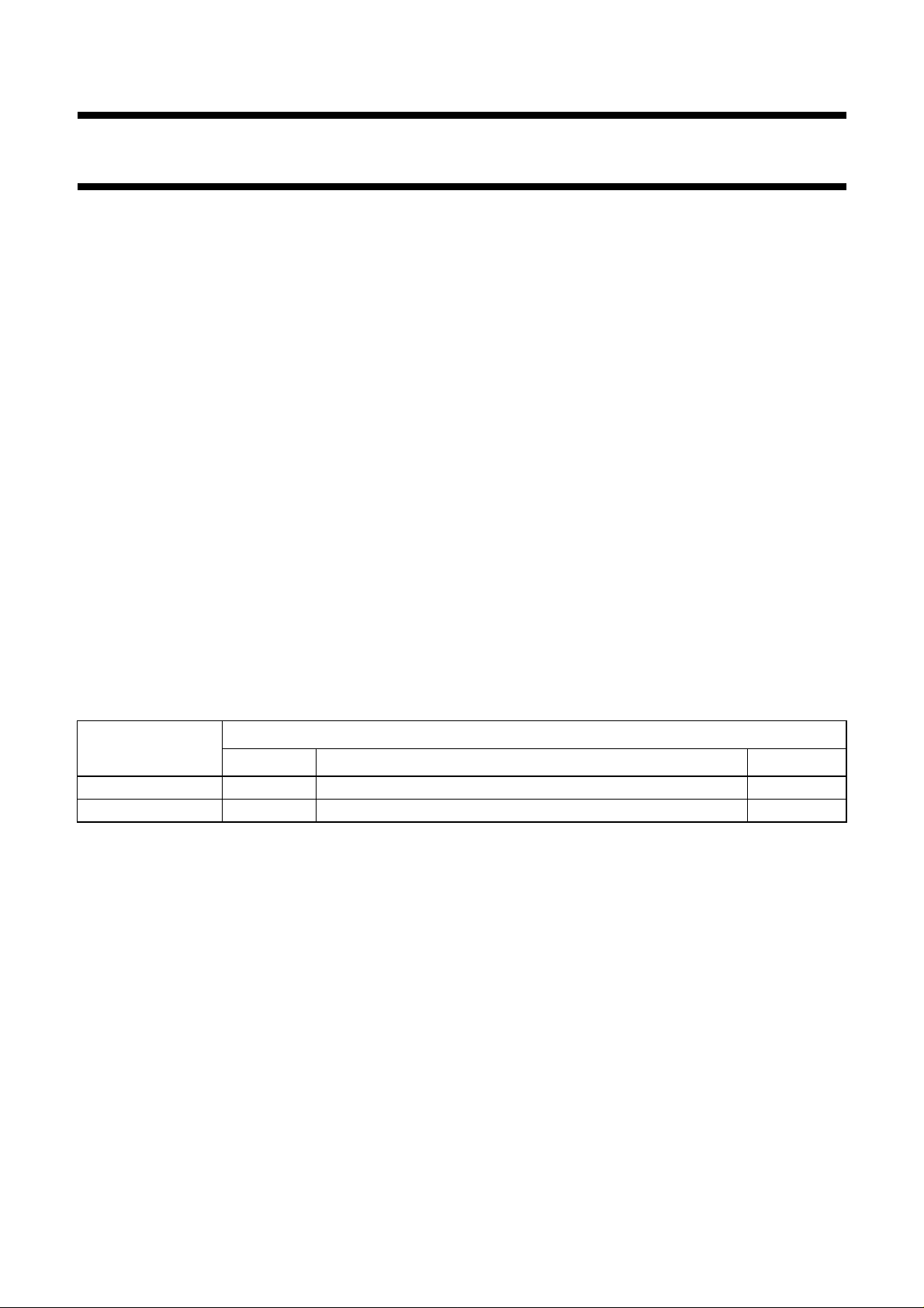
ORDERING INFORMATION
TYPE NUMBER
NAME DESCRIPTION VERSION
TDA9817 SDIP24 plastic shrink dual in-line package; 24 leads (400 mil) SOT234-1
TDA9818 SDIP24 plastic shrink dual in-line package; 24 leads (400 mil) SOT234-1
PACKAGE
1997 May 12 2
Page 3
Philips Semiconductors Preliminary specification
Single/multistandard VIF/SIF-PLL and
TDA9817; TDA9818
FM-PLL/AM demodulators
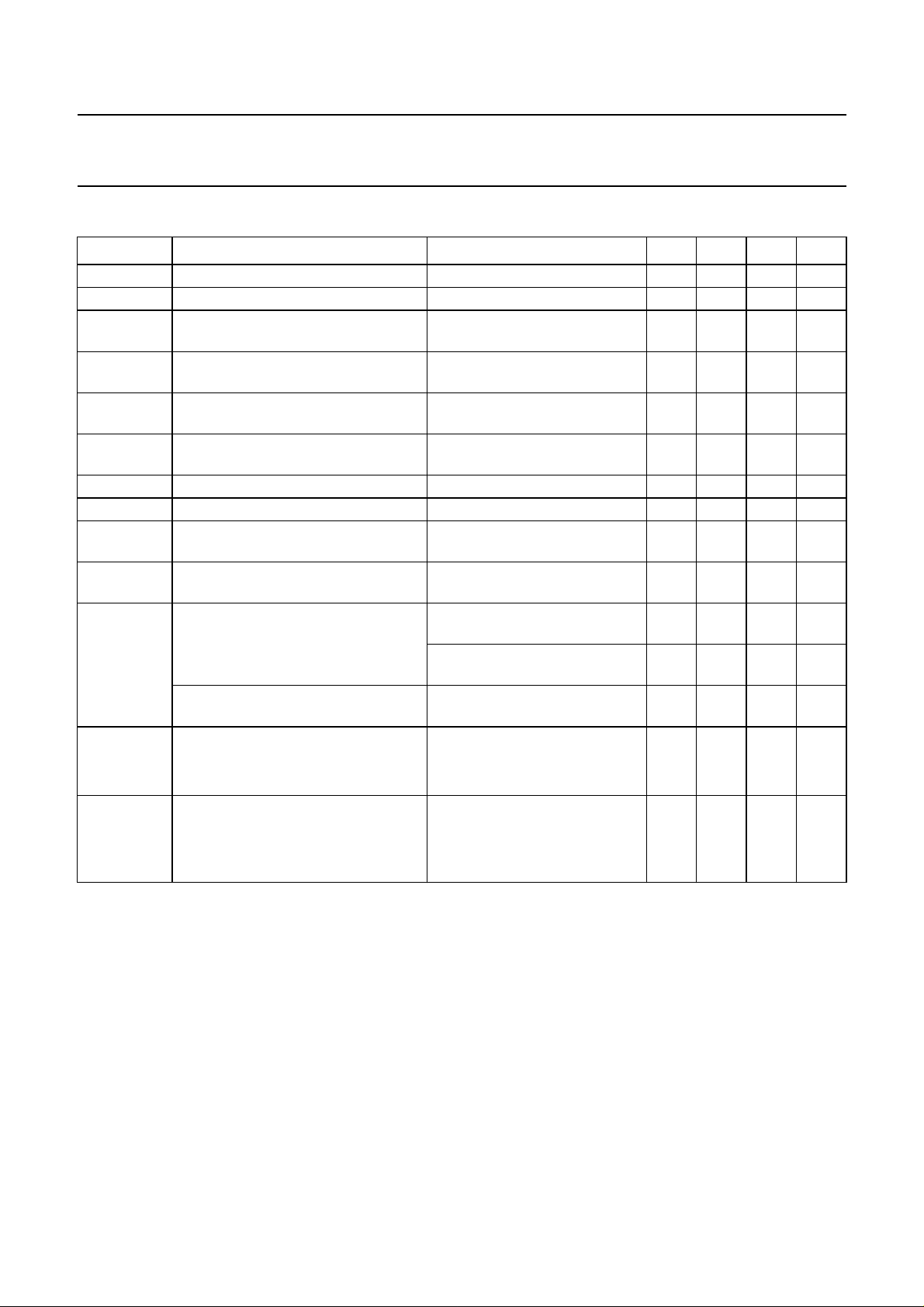
QUICK REFERENCE DATA
SYMBOL PARAMETER CONDITIONS MIN. TYP. MAX. UNIT
V
P
I
P
V
i(VIF)(rms)
V
o(video)(p-p)
B
−3
S/N
W
α
IM(1.1)
α
IM(3.3)
α
H(sup)
V
i(SIF)(rms)
V
o(rms)
THD
audio
S/N
W(audio)
supply voltage 4.5 5 5.5 V
supply current 76 90 104 mA
vision IF input signal voltage
−1 dB video at output − 60 100 µV
sensitivity (RMS value)
video output signal voltage
0.97 1.1 1.23 V
(peak-to-peak value)
−3 dB video bandwidth on pin 16 B/G and L standard;
< 20 pF; RL>1kΩ; AC load
C
L
weighted signal-to-noise ratio for
78−MHz
56 60 − dB
video
intermodulation attenuation at ‘blue’ f = 1.1 MHz 58 64 − dB
intermodulation attenuation at ‘blue’ f = 3.3 MHz 58 64 − dB
suppression of harmonics in video
35 40 − dB
signal
sound IF input signal voltage
−3 dB at intercarrier output − 50 100 µV
sensitivity (RMS value)
audio output signal voltage for FM
(RMS value)
B/G standard;
27 kHz modulation (54%)
M, N standard;
0.4 0.5 0.6 V
0.36 0.45 0.54 V
25 kHz modulation
audio output signal voltage for AM
L standard; 54% modulation 0.4 0.5 0.6 V
(RMS value)
total harmonic distortion audio signal 54% modulation
FM − 0.2 0.5 %
AM − 0.5 1.0 %
weighted signal-to-noise ratio audio
54% modulation
signal
FM 55 60 − dB
AM 47 53 − dB
1997 May 12 3
Page 4
Philips Semiconductors Preliminary specification
Single/multistandard VIF/SIF-PLL and
FM-PLL/AM demodulators
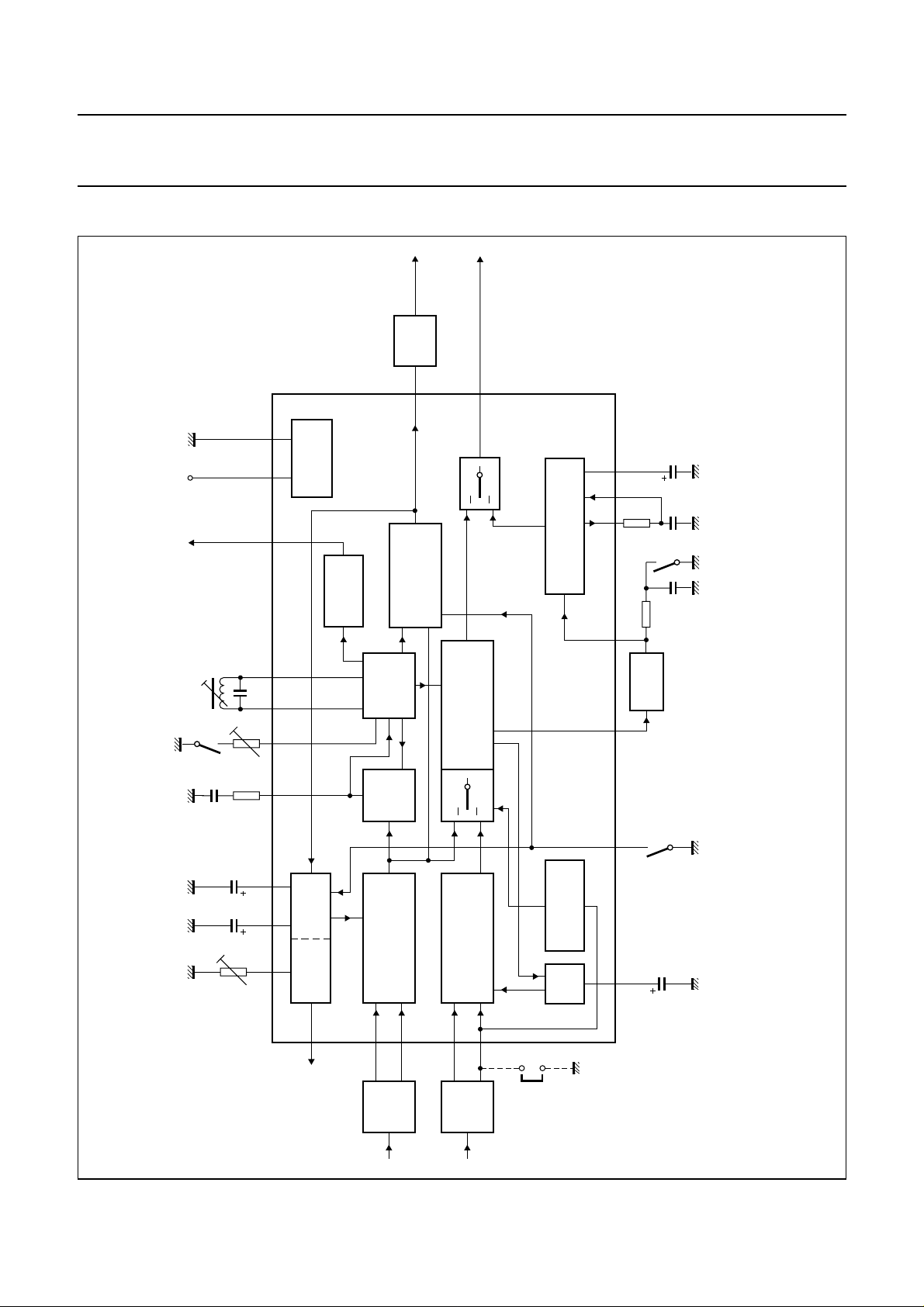
BLOCK DIAGRAM
video
SOUND
video
16
2021171819
GND
P
V
AFC
VOLTAGE
REFERENCE
AFC
VIDEO
DETECTOR
(p-p)
audio
1 V
TRAP
(p-p)
1.1 V
8
AND AMPLIFIER
DEMODULATOR
10 11
9
FM-PLL
DEMODULATOR
13
TDA9817; TDA9818
MHA663
DEC
C
de-em
C
mute
switch
pc
2 × f
and adjust
L/L accent switch
PLL
T
VAGC
C
BL
C
TOP
(1)
615
422
(1)
7
VIF
AGC
AGC
TUNER
14
tuner AGC
VCO
TWD
QSS MIXER
AM DEMODULATOR
INTERCARRIER MIXER
TDA9817
TDA9818
MODE SWITCH
INTERCARRIER
VIF AMPLIFIER FPLL
2
1
VIF
SAW
SIF AMPLIFIER
24
23
SIF
SAW
SIF
mode
intercarrier
AGC
5.5 MHz
12
handbook, full pagewidth
Fig.1 Block diagram.
(1)
3
switch
selection
standards
5
SAGC
C
(1) Not connected for TDA9817.
1997 May 12 4
Page 5
Philips Semiconductors Preliminary specification
Single/multistandard VIF/SIF-PLL and
FM-PLL/AM demodulators
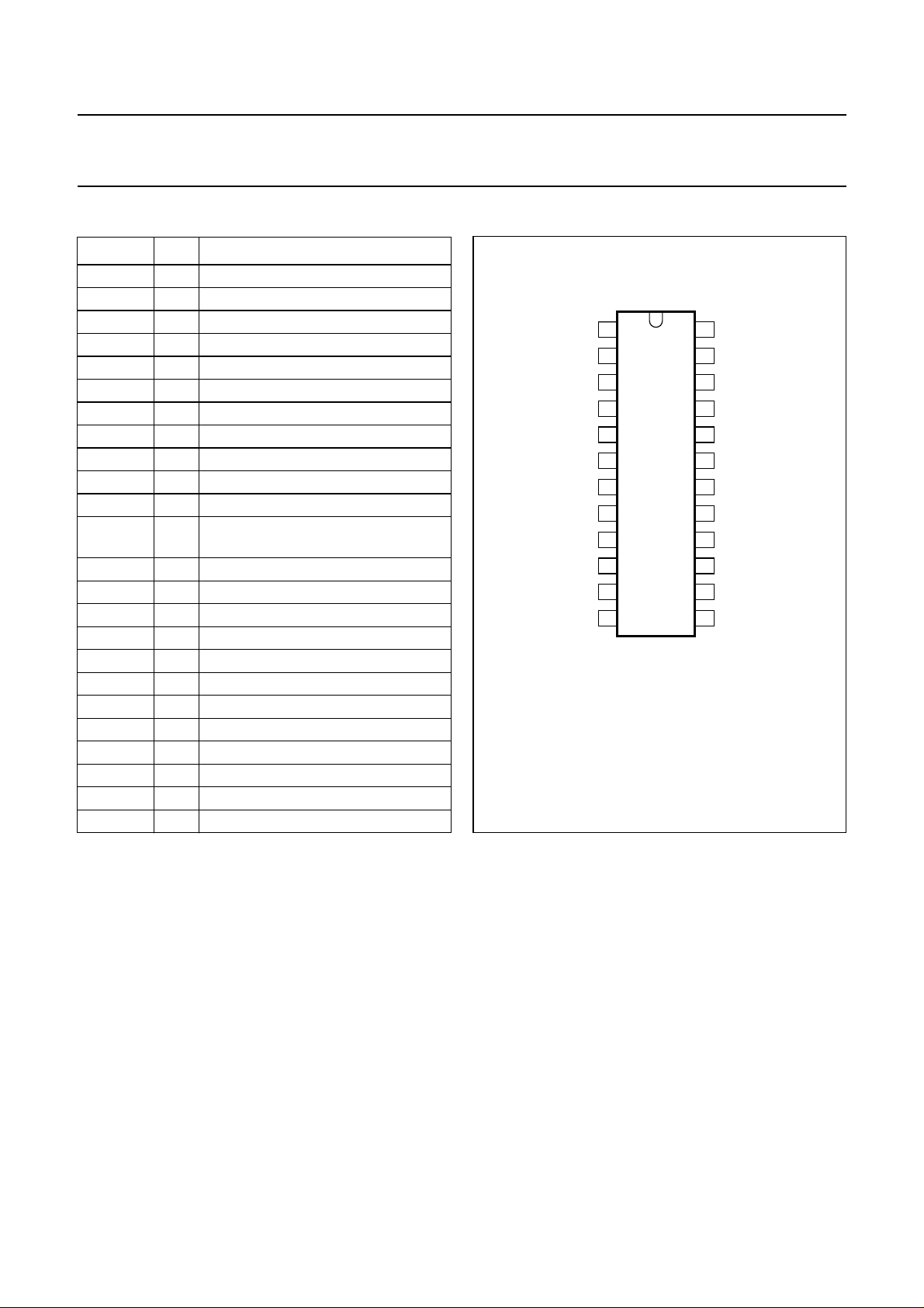
PINNING
SYMBOL PIN DESCRIPTION
V
i VIF1
V
i VIF2
(1)
STD
C
VAGC
C
SAGC
T
PLL
(1)
LADJ
V
oAF
V
de-em
C
de-em
C
DEC
V
o QSS
V
iFM
TAGC 14 tuner AGC output
(1)
C
BL
V
o(vid)
AFC 17 AFC output
VCO1 18 VCO1 resonance circuit
VCO2 19 VCO2 resonance circuit
GND 20 ground
V
P
TADJ 22 tuner AGC takeover point adjust
V
i SIF1
V
i SIF2
1 VIF differential input signal voltage 1
2 VIF differential input signal voltage 2
3 standard switch
4 VIF AGC capacitor
5 SIF AGC capacitor
6 PLL loop filter
7 L/L accent switch and adjust
8 audio output
9 de-emphasis input
10 de-emphasis output
11 decoupling capacitor
single reference QSS/intercarrier
12
output voltage
13 sound intercarrier input voltage
15 black level detector
16 composite video output voltage
21 supply voltage
23 SIF differential input signal voltage 1
24 SIF differential input signal voltage 2
handbook, halfpage
(1) Not connected for TDA9817.
V
V
C
C
LADJ
V
C
V
i VIF1
i VIF2
STD
VAGC
SAGC
T
PLL
V
o AF
de-em
de-em
C
DEC
o QSS
1
2
(1)
3
4
5
6
(1)
7
8
9
10
11
12
Fig.2 Pin configuration.
TDA9817; TDA9818
V
24
i SIF2
V
23
i SIF1
TADJ
22
V
21
P
GND
20
VCO2
MHA664
19
VCO1
18
AFC
17
V
16
o(vid)
(1)
C
15
BL
TAGC
14
13
V
i FM
TDA9818
TDA9817
Note
1. Not connected for TDA9817.
1997 May 12 5
Page 6

Philips Semiconductors Preliminary specification
Single/multistandard VIF/SIF-PLL and
FM-PLL/AM demodulators
FUNCTIONAL DESCRIPTION
The integrated circuit comprises the functional blocks as
shown in Fig.1:
• Vision IF amplifier and VIF AGC detector
• Tuner AGC
• Frequency Phase Locked Loop detector (FPLL)
• VCO, Travelling Wave Divider (TWD) and AFC
• Video demodulator and amplifier
• SIF amplifier and SIF AGC
• Single reference QSS mixer
• AM demodulator
• FM-PLL demodulator
• AF (Audio Frequency) signal processing
• Internal voltage stabilizer.
Vision IF amplifier and VIF AGC detector
The vision IF amplifier consists of three AC-coupled
differential amplifier stages. Each differential stage
comprises a feedback network controlled by emitter
degeneration.
The AGC detector generates the required VIF gain control
voltage for constant video output by charging/discharging
the AGC capacitor. Therefore for negative video
modulation the sync level and for positive video
modulation the peak white level of the video signal is
detected. In order to reduce the reaction time for positive
modulation, where a very large time constant is needed,
an additional level detector increases the discharging
current of the AGC capacitor (fast mode) in the event of a
decreasing VIF amplitude step. The additional level
information is given by the black-level detector voltage.
Tuner AGC
The AGC capacitor voltage is converted to an internal IF
control signal, and is fed to the tuner AGC to generate the
tuner AGC output current at pin TAGC (open-collector
output). The tuner AGC takeover point can be adjusted at
pin TADJ. This allows to match the tuner to the SAW filter
in order to achieve the optimum IF input level.
Frequency Phase Locked Loop detector (FPLL)
The VIF-amplifier output signal is fed into a frequency
detector and into a phase detector via a limiting amplifier.
During acquisition the frequency detector produces a DC
current proportional to the frequency difference between
the input and the VCO signal. After frequency lock-in the
phase detector produces a DC current proportional to the
TDA9817; TDA9818
phase difference between the VCO and the input signal.
The DC current of either frequency detector or phase
detector is converted into a DC voltage via the loop filter,
which controls the VCO frequency. In the event of positive
modulated signals the phase detector is gated by
composite sync in order to avoid signal distortion for
overmodulated VIF signals.
VCO, Travelling Wave Divider (TWD) and AFC
The VCO operates with a resonance circuit (with L and C
in parallel) at double the PC frequency. The VCO is
controlled by two integrated variable capacitors.
The control voltage required to tune the VCO from its
free-running frequency to actually double the PC
frequency is generated by the frequency-phase detector
(FPLL) and fed via the loop filter to the first variable
capacitor. This control voltage is amplified and additionally
converted into a current which represents the AFC output
signal. At centre frequency the AFC output current is equal
to zero.
For TDA9818: the VCO centre frequency can be
decreased (required for L accent standard) by activating
an additional internal capacitor. This is achieved by using
the L accent switch. In this event the second variable
capacitor can be controlled by a variable resistor at the L
accent switch for setting the VCO centre frequency to the
required L accent value.
The oscillator signal is divided by 2 with a TWD which
generates two differential output signals with a 90 degree
phase difference independent of the frequency.
Video demodulator and amplifier
The video demodulator is realized by a multiplier which is
designed for low distortion and large bandwidth. The vision
IF input signal is multiplied with the ‘in phase’ signal of the
travelling wave divider output. In the demodulator stage
the video signal polarity can be switched in accordance
with the TV standard.
The demodulator output signal is fed via an integrated
low-pass filter for attenuation of the carrier harmonics to
the video amplifier. The video amplifier is realized by an
operational amplifier with internal feedback and high
bandwidth. A low-pass filter is integrated to achieve an
attenuation of the carrier harmonics for B/G and
L standard. The standard dependent level shift in this
stage delivers the same sync level for positive and
negative modulation. The video output signal at V
1.1 V (p-p) for nominal vision IF modulation, in order to
achieve 1 V (p-p) at sound trap output.
o(vid)
is
1997 May 12 6
Page 7

Philips Semiconductors Preliminary specification
Single/multistandard VIF/SIF-PLL and
FM-PLL/AM demodulators
SIF amplifier and SIF AGC
The sound IF amplifier consists of two AC-coupled
differential amplifier stages. Each differential stage
comprises a controlled feedback network provided by
emitter degeneration.
The SIF AGC detector is related to the SIF input signal
(average level of AM or FM carrier) and controls the SIF
amplifier to provide a constant SIF signal to the
AM demodulator and single reference QSS mixer.
At L standard (AM sound) the SIF AGC reaction time is set
to ‘slow’ for nominal video conditions. But with a
decreasing VIF amplitude step the SIF AGC is set to ‘fast’
mode controlled by the VIF AGC detector. In FM mode this
reaction time is always ‘fast’.
Single reference QSS mixer
The single reference QSS mixer is realized by a multiplier.
The SIF amplifier output signal is fed to the single
reference QSS mixer and converted to intercarrier
frequency by the regenerated picture carrier (VCO).
The mixer output signal is fed via a high-pass for
attenuation of the video signal components to the output
pin 12. With this system a high performance hi-fi stereo
sound processing can be achieved.
For a simplified application without a sound IF SAW filter
the single reference QSS mixer can be switched to the
intercarrier mode by connecting pin 24 to ground. In this
mode the sound IF passes the vision IF SAW filter and the
composite IF signal is fed to the single reference QSS
mixer. This IF signal is multiplied with the 90 degree TWD
output signal for converting the sound IF to intercarrier
frequency. This composite intercarrier signal is fed to the
output pin 12, too. By using this quadrature detection, the
low frequency video signals are removed.
AM demodulator
The AM demodulator is realized by a multiplier.
The modulated SIF amplifier output signal is multiplied in
phase with the limited (AM is removed) SIF amplifier
output signal. The demodulator output signal is fed via an
integrated low-pass filter for attenuation of the carrier
harmonics to the AF amplifier.
TDA9817; TDA9818
consists of 7 stages which are internally AC-coupled in
order to minimize the DC offset.
Furthermore the AF output signal can be muted by
connecting a resistor between the limiter input pin 13 and
ground.
The FM-PLL consists of an integrated relaxation oscillator,
an integrated loop filter and a phase detector.
The oscillator is locked to the FM intercarrier signal, output
from the limiter. As a result of locking, the oscillator
frequency tracks with the modulation of the input signal
and the oscillator control voltage is superimposed by the
AF voltage. The FM-PLL operates as an FM demodulator.
AF signal processing
The AF amplifier consists of two parts:
1. The AF pre-amplifier for FM sound is an operational
amplifier with internal feedback, high gain and high
common mode rejection. The AF voltage from the
PLL demodulator, by principle a small output signal, is
amplified by approximately 33 dB. The low-pass
characteristic of the amplifier reduces the harmonics of
the intercarrier signal at the sound output terminal
pin 9 at which the de-emphasis network for FM sound
is applied. An additional DC control circuit is
implemented to keep the DC level constant,
independent of process spread.
2. The AF output amplifier (10 dB) provides the required
output level by a rail-to-rail output stage. This amplifier
makes use of an input selector for switching to AM, FM
de-emphasis or mute state, controlled by the standard
switching voltage and the mute switching voltage.
Internal voltage stabilizer
The bandgap circuit internally generates a voltage of
approximately 1.25 V, independent of supply voltage and
temperature. A voltage regulator circuit, connected to this
voltage, produces a constant voltage of 3.6 V which is
used as an internal reference voltage.
FM-PLL demodulator
The FM-PLL demodulator consists of a limiter and an
FM-PLL. The limiter provides the amplification and
limitation of the FM sound intercarrier signal. The result is
high sensitivity and AM suppression. The amplifier
1997 May 12 7
Page 8
Philips Semiconductors Preliminary specification
Single/multistandard VIF/SIF-PLL and
TDA9817; TDA9818
FM-PLL/AM demodulators
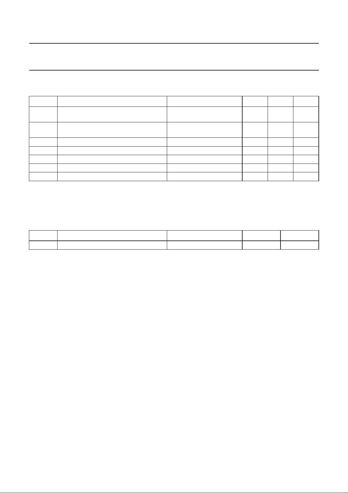
LIMITING VALUES
In accordance with the Absolute Maximum Rating System (IEC 134).
SYMBOL PARAMETER CONDITIONS MIN. MAX. UNIT
V
P
V
i
t
sc(max)
V
TAGC
T
stg
T
amb
V
es
Notes
1. I
P
2. Machine model class B.
supply voltage maximum chip temperature
− 5.5 V
of 110 °C; note 1
voltage at pins 1 to 6, 9 to 11, 13to15, 17
0V
and 21 to 24
maximum short-circuit time to ground or V
P
− 10 s
tuner automatic gain control output voltage 0 13.2 V
storage temperature −25 +150 °C
operating ambient temperature −20 +70 °C
electrostatic handling voltage note 2 −300 +300 V
= 104 mA; T
=70°C; R
amb
th j-a
= 65 K/W.
P
V
THERMAL CHARACTERISTICS
SYMBOL PARAMETER CONDITIONS VALUE UNIT
R
th j-a
thermal resistance from junction to ambient in free air 65 K/W
1997 May 12 8
Page 9
Philips Semiconductors Preliminary specification
Single/multistandard VIF/SIF-PLL and
TDA9817; TDA9818
FM-PLL/AM demodulators
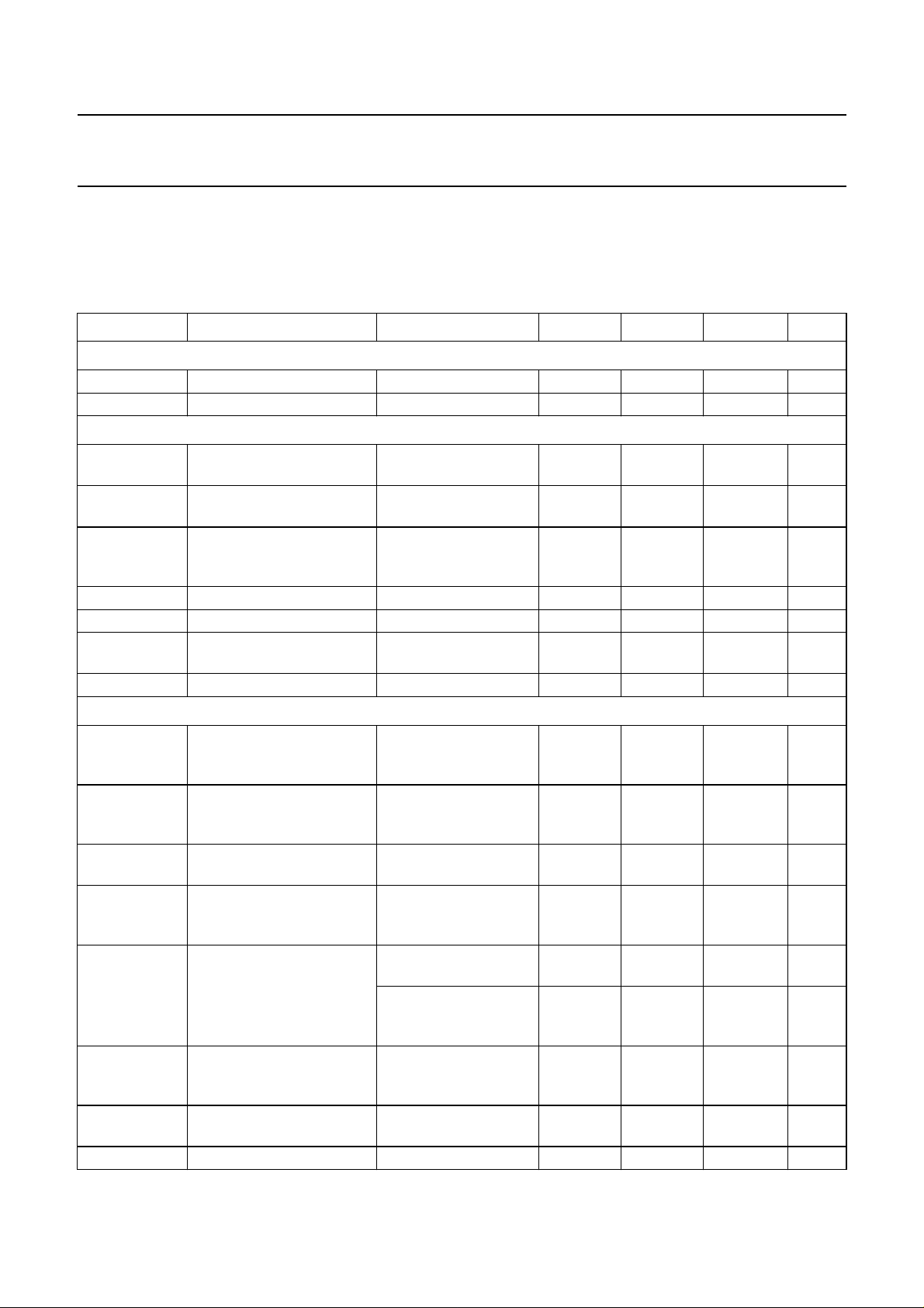
CHARACTERISTICS
V
=5V; T
P
peak white level for L); IF input from 50 Ω via broadband transformer 1 : 1; video modulation DSB; residual carrier
B/G: 10%; L = 3%; video signal in accordance with
Fig.13; unless otherwise specified.
SYMBOL PARAMETER CONDITIONS MIN. TYP. MAX. UNIT
Supply (pin 21)
V
P
I
P
Vision IF amplifier (pins 1 and 2)
V
i(VIF)(rms)
V
i(max)(rms)
∆V
o(int)
G
IF(cr)
R
i(diff)
C
i(diff)
V
I(1,2)
True synchronous video demodulator; note 3
f
VCO(max)
∆f
/∆T oscillator drift as a function
osc
∆f
/∆V
osc
V
VCO(rms)
f
cr(pc)
∆f
pc(fr)
f
alg(L accent)
t
acq
=25°C; see Table 1 for input frequencies and level; input level V
amb
“CCIR, line 17”
supply voltage note 1 4.5 5 5.5 V
supply current 76 90 104 mA
input signal voltage
sensitivity (RMS value)
maximum input signal
voltage (RMS value)
internal IF amplitude
difference between picture
and sound carrier
B/G standard;
−1 dB video at output
B/G standard;
+1 dB video at output
within AGC range;
B/G standard;
∆f = 5.5 MHz
IF gain control range see Fig.3 65 70 − dB
differential input resistance note 2 1.7 2.2 2.7 kΩ
differential input
note 2 1.2 1.7 2.5 pF
capacitance
DC input voltage note 2 − 3.4 − V
maximum oscillator
f=2f
pc
frequency for carrier
regeneration
oscillator is
of temperature
free-running; I
AFC
=0;
note 4
P
oscillator shift as a function
of supply voltage
oscillator is
free-running; note 4
oscillator voltage swing at
pins 18 and 19
(RMS value)
picture carrier capture
range
B/G, M, N
and L standard
L accent standard;
f
= 33.9 MHz;
pc
R7= 5.6 kΩ
picture carrier frequency
(free-running) accuracy
L accent standard;
fpc= 33.9 MHz;
R7= 5.6 kΩ
L accent alignment
frequency range
L accent standard;
I
=0
AFC
acquisition time BL = 70 kHz; note 5 −−30 ms
i(VIF)(rms)
or
“NTC-7 Composite”
= 10 mV (sync-level for B/G,
; measurements taken in
− 60 100 µV
120 200 − mV
− 0.7 1 dB
125 130 − MHz
−−±20 × 10−6K
−−±1.5 × 10⁻³V
50 80 110 mV
±1.4 ±1.8 − MHz
±0.9 ±1.2 − MHz
−±200 ±400 kHz
±400 ±600 − kHz
−1
−1
1997 May 12 9
Page 10
Philips Semiconductors Preliminary specification
Single/multistandard VIF/SIF-PLL and
TDA9817; TDA9818
FM-PLL/AM demodulators
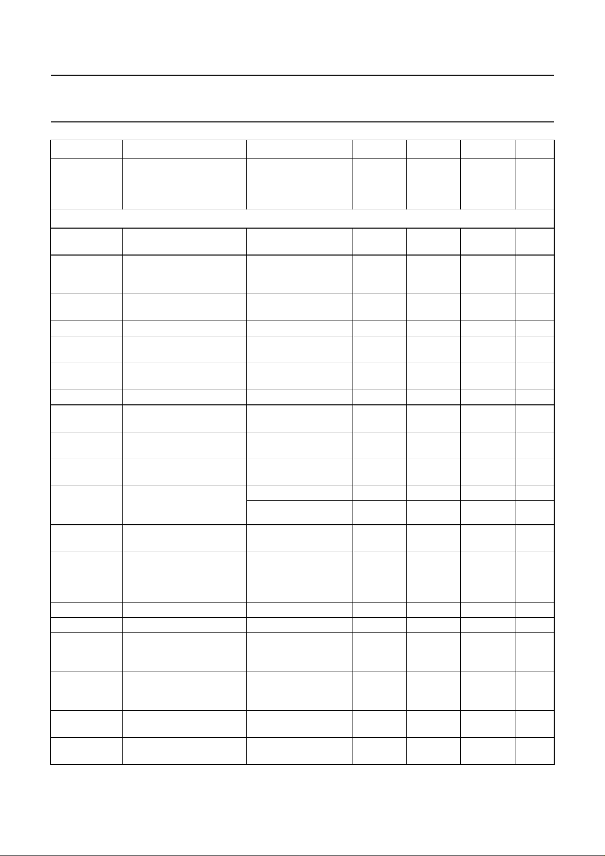
SYMBOL PARAMETER CONDITIONS MIN. TYP. MAX. UNIT
V
i(IF)(rms)
Composite video amplifier (pin 16; sound carrier off)
V
o(video)(p-p)
V/S ratio between video
∆V
o(video)
V
sync(16)
V
clu(16)
V
cll(16)
R
o(16)
I
bias(16)(int)
I
o(sink)(16)(max)
I
o(source)(16)(max)
∆V
o
∆V
o(blBG)
∆V
o(blL)
G
diff
ϕ
diff
B
−1
B
−3
S/N
W
S/N unweighted signal-to-noise
IF input signal voltage
sensitivity for PLL to be
maximum IF gain;
note 6
− 30 70 µV
locked (RMS value;
pins 1 and 2)
output signal voltage
see Fig.8 0.97 1.1 1.23 V
(peak-to-peak value)
1.9 2.33 3.0
(black-to-white) and sync
level
output signal voltage
difference
difference between
B/G and L standard
−−±12 %
sync voltage level B/G and L standard 1.4 1.5 1.6 V
upper video clipping
VP− 1.1 VP− 1 − V
voltage level
lower video clipping voltage
− 0.7 0.9 V
level
output resistance note 2 −−10 Ω
internal DC bias current for
2.2 3.0 − mA
emitter-follower
maximum AC and DC
1.6 −−mA
output sink current
maximum AC and DC
2.9 −−mA
output source current
deviation of CVBS output
signal voltage at
50 dB gain control −−0.5 dB
30 dB gain control −−0.1 dB
B/G standard
black level tilt in
gain variation; note 7 −−1%
B/G standard
vertical black level tilt for
worst case in L standard
vision carrier
modulated by test line
−−1.9 %
(VITS) only; gain
variation; note 7
differential gain
differential phase
−1 dB video bandwidth B/G and L standard;
“CCIR, line 330”
“CCIR, line 330”
− 25%
− 1 2 deg
56−MHz
CL< 50 pF; RL> 1kΩ;
AC load
−3 dB video bandwidth B/G and L standard;
78−MHz
CL< 50 pF; RL> 1kΩ;
AC load
weighted signal-to-noise
see Fig.5 and note 8 56 60 − dB
ratio
see Fig.5 and note 8 49 53 − dB
ratio
1997 May 12 10
Page 11

Philips Semiconductors Preliminary specification
Single/multistandard VIF/SIF-PLL and
TDA9817; TDA9818
FM-PLL/AM demodulators
SYMBOL PARAMETER CONDITIONS MIN. TYP. MAX. UNIT
α
IM(1.1)
α
IM(3.3)
∆f
unwanted(p-p)
∆ϕ robustness for modulator
α
c(rms)
α
H(sup)
α
H(spur)
PSRR power supply ripple
intermodulation
attenuation at ‘blue’
intermodulation
attenuation at ‘yellow’
intermodulation
attenuation at ‘blue’
intermodulation
attenuation at ‘yellow’
robustness for unwanted
frequency deviation of
picture carrier
(peak-to-peak value)
imbalance
f = 1.1 MHz; see Fig.6
and note 9
f = 1.1 MHz; see Fig.6
and note 9
f = 3.3 MHz; see Fig.6
and note 9
f = 3.3 MHz; see Fig.6
and note 9
L standard;
residual carrier: 3%;
serration pulses: 50%;
note 2
L standard;
residual carrier: 0%;
58 64 − dB
60 66 − dB
58 64 − dB
59 65 − dB
−−12 kHz
−−3%
serration pulses: 50%;
note 2
residual vision carrier
(RMS value)
fundamental wave and
harmonics; B/G and
− 25mV
L standard
suppression of video
note 10a 35 40 − dB
signal harmonics
spurious elements note 10b 40 −−dB
video signal; grey
rejection at pin 16
level; see Fig.11
B/G standard 30 35 − dB
L standard 26 30 − dB
VIF-AGC detector (pin 4)
I
4
charging current B/G and L standard;
note 7
additional charging current L standard in event of
missing VITS pulses
and no white video
content
discharging current B/G standard 15 20 25 µA
normal mode L 225 300 375 nA
fast mode L 30 40 50 µA
t
resp
AGC response to an
increasing VIF step
AGC response to a
decreasing VIF step
B/G and L standard;
note 11
B/G standard − 2.2 3.5 ms/dB
fast mode L − 1.1 1.8 ms/dB
normal mode L;
note 11
∆IF VIF amplitude step for
L standard −2 −6 −10 dB
activating fast AGC mode
1997 May 12 11
0.75 1 1.25 mA
1.9 2.5 3.1 µA
− 0.05 0.1 ms/dB
− 150 240 ms/dB
Page 12

Philips Semiconductors Preliminary specification
Single/multistandard VIF/SIF-PLL and
TDA9817; TDA9818
FM-PLL/AM demodulators
SYMBOL PARAMETER CONDITIONS MIN. TYP. MAX. UNIT
V
th(15)
Tuner AGC (pin 14)
V
i(rms)
V
) permissible output voltage from external source;
o(14
V
sat(14)
∆V
I
14(sink)
∆G
/∆T variation of takeover point
TOP(14)
IF
threshold voltage level
additional charging current
see Fig.8
L standard 1.95 2.0 2.05 V
L standard; fast
1.6 1.66 1.72 V
mode L
IF input signal voltage for
minimum starting point of
tuner takeover (RMS value)
IF input signal voltage for
maximum starting point of
tuner takeover (RMS value)
input at pins 1 and 2;
R
=22kΩ;
TOP
I14= 0.4 mA
input at pins 1 and 2;
R
=0Ω;
TOP
I14= 0.4 mA
− 25mV
50 100 − mV
−−13.2 V
note 2
saturation voltage I14= 1.5 mA −−0.2 V
I14= 0.4 mA − 0.03 0.07 dB/K
by temperature
sink current see Fig.3
no tuner gain
−−5µA
reduction;
V
= 13.2 V
14
maximum tuner gain
1.5 2 2.6 mA
reduction
IF slip by automatic gain
control
tuner gain current from
20 to 80%
− 68dB
AFC circuit (pin 17); see Fig.7 and note 12
S control steepness ∆I17/∆f note 13
33.9 MHz 0.5 0.75 1.0 µA/kHz
38.9 MHz 0.5 0.75 1.0 µA/kHz
45.75 MHz 0.45 0.65 0.85 µA/kHz
58.75 MHz 0.38 0.55 0.72 µA/kHz
/∆T frequency variation by
∆f
IF
temperature
B/G and L standard;
I
= 0; note 4
AFC
L accent standard;
I
= 0; note 4
AFC
V
o(17)
output voltage upper limit VP − 0.6 VP − 0.3 − V
output voltage lower limit − 0.3 0.6 V
I
o(source)(17)
I
o(sink)(17)
∆I
17(p-p)
output source current 150 200 250 µA
output sink current 150 200 250 µA
residual video modulation
B/G and L standard − 20 30 µA
current (peak-to-peak
value)
1997 May 12 12
−−±20 × 10−6K
−−±60 × 10−6K
−1
−1
Page 13
Philips Semiconductors Preliminary specification
Single/multistandard VIF/SIF-PLL and
TDA9817; TDA9818
FM-PLL/AM demodulators
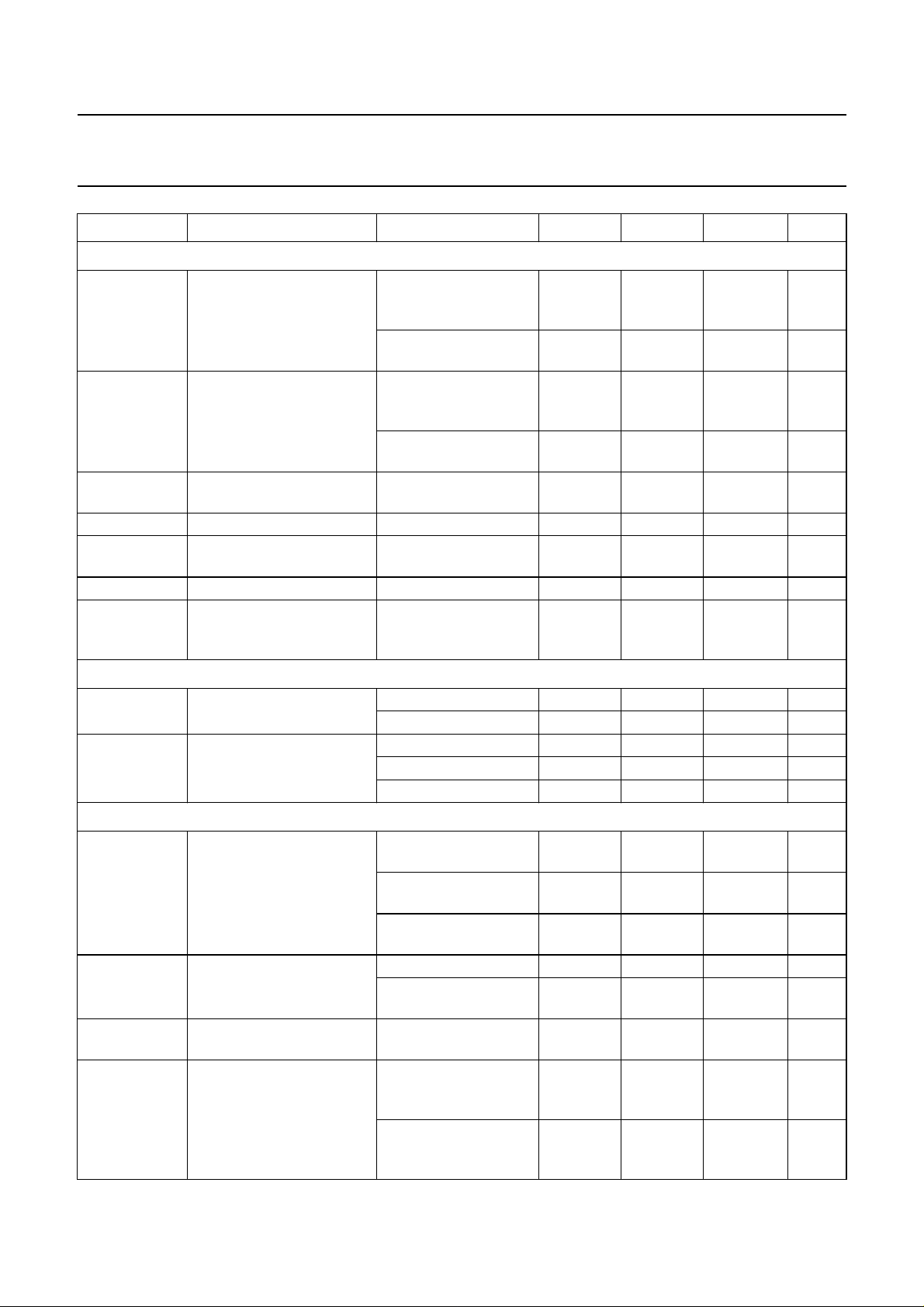
SYMBOL PARAMETER CONDITIONS MIN. TYP. MAX. UNIT
Sound IF amplifier (pins 23 and 24)
V
i(SIF)(rms)
V
i(max)(rms)
G
cr(SIF)
R
i(diff)
C
i(diff)
V
I(23,24)
α
SIF,VIF
input signal voltage
sensitivity (RMS value)
maximum input signal
voltage (RMS value)
SIF gain control range FM and AM mode;
differential input resistance note 2 1.7 2.2 2.7 kΩ
differential input
capacitance
DC input voltage − 3.4 − V
crosstalk attenuation
between SIF and VIF input
FM mode; −3 dB at
− 50 100 µV
intercarrier output
pin 12
AM mode; −3 dB at
− 50 100 µV
AF output pin 8
FM mode; +1 dB at
65 100 − mV
intercarrier output
pin 12
AM mode; +1 dB at
65 100 − mV
AF output pin 8
60 66 − dB
see Fig.4
note 2 1.2 1.7 2.5 pF
between pins 1 and 2
50 −−dB
and pins 23 and 24;
note 14
SIF AGC detector (pin 5)
I
ch(5)
charging current FM mode 8 12 16 µA
AM mode 0.8 1.2 1.6 µA
I
dch(5)
discharging current FM mode 8 12 16 µA
normal mode AM 1 1.4 1.8 µA
fast mode AM 60 85 110 µA
Single reference QSS intercarrier mixer (B/G standard; pin 12)
V
o(rms)
IF intercarrier level
(RMS value)
QSS mode; SC1;
sound carrier 2 off
L standard; without
modulation
intercarrier mode; SC1;
sound carrier 2 off
V
o(peak)
IF intercarrier level
(peak value)
QSS mode 141 198 225 mV
L standard;
80% AM modulation
B
−3
−3 dB intercarrier
upper limit 7.5 9 − MHz
bandwidth
α
SC(rms)
residual sound carrier
(RMS value)
QSS mode;
fundamental wave and
harmonics
intercarrier mode;
fundamental wave and
harmonics
100 140 180 mV
100 140 180 mV
− note 15 − mV
255 356 458 mV
− 25mV
− 25mV
1997 May 12 13
Page 14
Philips Semiconductors Preliminary specification
Single/multistandard VIF/SIF-PLL and
TDA9817; TDA9818
FM-PLL/AM demodulators
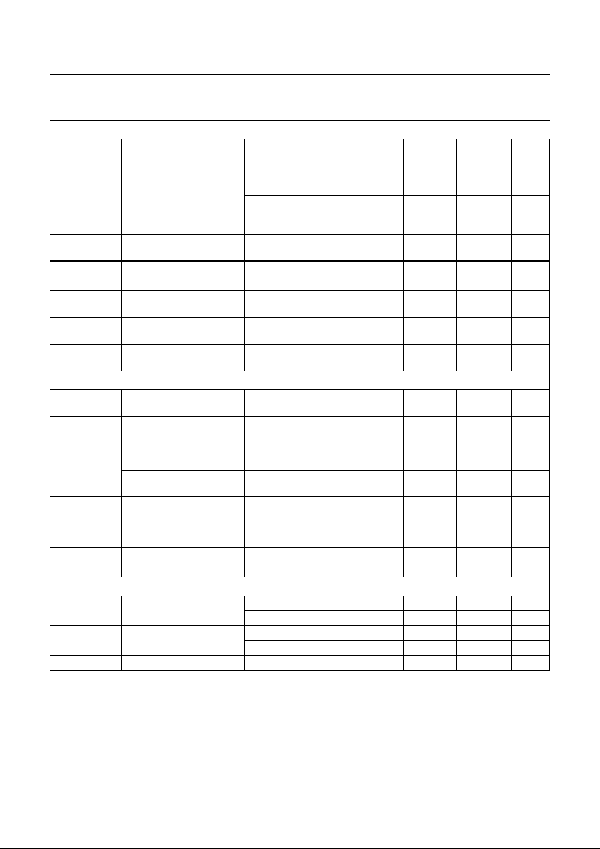
SYMBOL PARAMETER CONDITIONS MIN. TYP. MAX. UNIT
α
C(rms)
α
H(sup)
R
o(12)
V
O(12)
I
int(12)
I
sink(max)(12)
I
source(max)(12)
Limiter amplifier (pin 13); note 16
V
i(FM)(rms)
V
i(FM)(rms)
residual vision carrier
(RMS value)
QSS mode;
fundamental wave and
− 25mV
harmonics
intercarrier mode;
− 520mV
fundamental wave and
harmonics
suppression of video
signal harmonics
intercarrier mode;
f
≤ 5 MHz
video
39 −−dB
output resistance note 2 −−25 Ω
DC output voltage − 2.0 − V
DC internal bias current for
1.9 2.5 − mA
emitter-follower
maximum AC and DC
1.4 1.9 − mA
output sink current
maximum AC and DC
3.0 3.5 − mA
output source current
input signal voltage for
−−100 µV
lock-in (RMS value)
input signal voltage
(RMS value)
SN+
-------------N
weighted
− 250 400 µV
40 dB=
allowed input signal voltage
(RMS value)
α
R
V
AM
i(13)
I(13)
AM suppression 50 µs de-emphasis;
input resistance note 2 480 600 720 Ω
DC input voltage − 2.8 − V
FM-PLL demodulator
f
f
t
cr
hr
acq
catching range of PLL upper limit 7.0 −−MHz
holding range of PLL upper limit 9.0 −−MHz
acquisition time −−4µs
200 −−mV
46 50 − dB
AM: f = 1 kHz; m = 0.3
refer to 27 kHz
(54% FM deviation)
lower limit −−4.0 MHz
lower limit −−3.5 MHz
1997 May 12 14
Page 15
Philips Semiconductors Preliminary specification
Single/multistandard VIF/SIF-PLL and
TDA9817; TDA9818
FM-PLL/AM demodulators
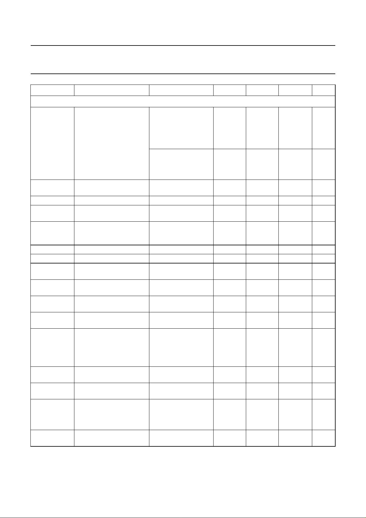
SYMBOL PARAMETER CONDITIONS MIN. TYP. MAX. UNIT
FM operation (B/G standard; pin 8); notes 16 and 16a
V
o(AF)(rms)
AF output signal voltage
(RMS value)
V
o(AF)(cl)
AF output clipping signal
voltage level
∆f
AF
∆V
/∆T temperature drift of AF
o
frequency deviation THD < 1.5%; note 17 −−±53 kHz
output signal voltage
V
9
DC voltage at decoupling
capacitor
R
8
V
8
I
sink(max)(8)
output resistance note 2 −−100 Ω
DC output voltage − 2.3 − V
maximum AC and DC
output sink current
I
source(max)(8)
maximum AC and DC
output source current
B
−3
−3 dB audio frequency
bandwidth
THD total harmonic distortion 27 kHz (54% FM
S/N
W
weighted signal-to-noise
ratio
α
SC(rms)
residual sound carrier
(RMS value)
α
8
mute attenuation of AF
signal
∆V
8
DC jump voltage of AF
output terminal for
switching AF output to
mute state and vice versa
PSRR power supply ripple
rejection at pin 8
27 kHz
(54% FM deviation);
see Fig.13 and note 17
= 470 Ω 200 250 300 mV
R
x
R
=0Ω 400 500 600 mV
x
25 kHz
360 450 540 mV
(50% FM deviation);
R
=0Ω; see Fig.13
x
and note 17
THD < 1.5% 1.0 − 1.2 V
voltage dependent on
− 3 × 10
−3
1.2 − 3.0 V
7 × 10
−3
VCO frequency;
note 18
−−0.5 mA
−−0.5 mA
without de-emphasis
100 125 − kHz
capacitor
− 0.2 0.5 %
deviation)
FM-PLL only; with
55 60 − dB
50 µs de-emphasis;
27 kHz (54% FM
deviation);
“CCIR 468-4”
fundamental wave and
−−75 mV
harmonics
B/G and L standard 70 75 − dB
FM-PLL in lock mode −±50 ±150 mV
R
=0Ω; f = 70 Hz;
x
20 26 − dB
see Figs 11 and 13
dB/K
1997 May 12 15
Page 16
Philips Semiconductors Preliminary specification
Single/multistandard VIF/SIF-PLL and
TDA9817; TDA9818
FM-PLL/AM demodulators
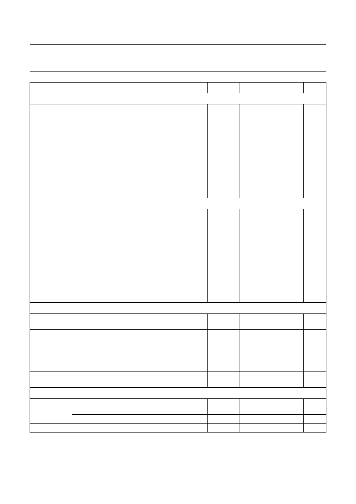
SYMBOL PARAMETER CONDITIONS MIN. TYP. MAX. UNIT
Single reference QSS AF performance for FM operation (B/G standard); notes 19, 20 and 21; see Table 1
S/N
W
weighted signal-to-noise
ratio
Intercarrier AF performance for FM operation (standard B/G) notes 19, 20 and 22; see Table 1
S/N
W
weighted signal-to-noise
ratio
PC/SC1 ratio at pins 1
40 −−dB
and 2; 27 kHz
(54% FM deviation);
“CCIR 468-4”
black picture 53 58 − dB
white picture 50 55 − dB
6 kHz sine wave
42 48 − dB
(black-to-white
modulation)
sound carrier
45 51 − dB
subharmonics;
f = 2.75 MHz ±3 kHz
PC/SC1 ratio at pins 1
27 −−dB
and 2; 27 kHz
(54% FM deviation);
“CCIR 468-4”
black picture 47 51 − dB
white picture 47 51 − dB
6 kHz sine wave
40 46 − dB
(black-to-white
modulation)
sound carrier
35 39 − dB
subharmonics;
f = 2.75 MHz ±3 kHz
AM operation (L standard; pin 8); note 23
V
o(AF)(rms)
AF output signal voltage
54% modulation 400 500 600 mV
(RMS value)
THD total harmonic distortion 54% modulation − 0.5 1.0 %
B
−3
S/N
W
−3 dB AF bandwidth 100 125 − kHz
weighted signal-to-noise
“CCIR 468-4”
47 53 − dB
ratio
V
8
PSRR power supply ripple
DC potential voltage − 2.3 − V
see Fig.11 20 26 − dB
rejection at pin 8
Switching level for standard switch (pin 3)
V
logic
DC potential for logic 1 or
B/G standard 2.8 − V
P
pin not connected
DC potential for logic 0 L/L accent standard 0 − 0.8 V
I
IL
LOW level input current V = 0 V 190 250 310 µA
1997 May 12 16
V
Page 17

Philips Semiconductors Preliminary specification
α
Single/multistandard VIF/SIF-PLL and
TDA9817; TDA9818
FM-PLL/AM demodulators
Notes to the characteristics
1. Values of video and sound parameters are decreased at VP= 4.5 V.
2. This parameter is not tested during production and is only given as an application information for designing the
television receiver.
3. Loop bandwidth BL = 70 kHz (natural frequency fn= 12 kHz; damping factor d ≈ 3; calculated with sync level within
gain control range). Resonance circuit of VCO: Q0> 50; C
approximately 2.7 V).
4. Temperature coefficient of external LC-circuit is equal to zero.
5. V
i(IF)(rms)
= 10 mV; ∆f = 1 MHz (VCO frequency offset related to picture carrier frequency); white picture
video modulation.
6. V
signal for nominal video signal.
iIF
7. The leakage current of the AGC capacitor should not exceed 1 µA at B/G standard respectively 10 nA current at
L standard. Larger currents will increase the tilt.
8. S/N is the ratio of black-to-white amplitude to the black level noise voltage (RMS value, pin 16). B = 5 MHz weighted
in accordance with
“CCIR 567”
.
9. The intermodulation figures are defined:
at 4.4 MHz
V
0
α
1.1
20
3.3
20
-------------------------------------V
at 1.1 MHz
0
at 4.4 MHz
V
0
log=
-------------------------------------V
at 3.3 MHz
0
; α
; α
3.6 dB+log=
value at 3.3 MHz referenced to colour carrier.
3.3
value at 1.1 MHz referenced to black/white signal;
1.1
10. Measurements taken with SAW filter K3953 (sound carrier suppression: 40 dB); loop bandwidth BL = 70 kHz:
a) Modulation VSB; sound carrier off; f
b) Sound carrier on; SIF SAW filter K9453; f
video
> 0.5 MHz.
= 10 kHz to 10 MHz.
video
11. Response speed valid for a VIF input level range of 200 µVupto70mV.
12. To match the AFC output signal to different tuning systems a current source output is provided. The test circuit is
given in Fig.7. The AFC-steepness can be changed by the resistors at pin 17.
13. Depending on the ratio ∆C/C0 of the LC resonant circuit of VCO (Q0> 50; see note 3; C0=C
14. Source impedance: 2.3 kΩ in parallel to 12 pF (SAW filter); fIF= 38.9 MHz.
15. Without using an SIF SAW filter the mixer can be switched to intercarrier mode by connecting pin 23 and/or pin 24
to ground. In this mode the SIF passes the VIF SAW filter and IF intercarrier levels are depending on the sound shelf
of the VIF SAW filter. The intercarrier output signal at pin 12 can be calculated by the following formula taking into
account the video output signal at pin 16 (V
V
-------------V
1
V
o(rms)
with = correction term for RMS value,
1.1 V p p–()
1
---------- -
× 10
---------- 22
-----------------------------------------------------------------
×=
i(SC)
i(PC)
o(video)(p-p)
dB()6dB 3dB±+
20
22
V
i(SC)
-------------V
i(PC)
= sound-to-picture carrier ratio at VIF input (pins 1 and 2) in dB,
dB()
6 dB = correction term of internal circuitry
and ±3 dB = tolerance of video output and intercarrier output amplitude V
Example: SAW filter G1962 (sound shelf: 20 dB) ⇒⇒ V
V
-------------V
= 8.2 pF ±0.25 pF; C
ext
int
= 1.1 V typical) as a reference:
.
o(rms)
i(SC)
i(PC)
27 dB–=
= 32 mV typical.
o(rms)
≈ 8.5 pF (loop voltage
int+Cext
).
1997 May 12 17
Page 18
Philips Semiconductors Preliminary specification
Single/multistandard VIF/SIF-PLL and
TDA9817; TDA9818
FM-PLL/AM demodulators
16. Input level for second IF from an external generator with 50 Ω source impedance. AC-coupled with 10 nF capacitor,
f
= 1 kHz, 27 kHz (54% FM deviation) of audio references. A VIF/SIF input signal is not permitted. Pins 5 and 4
mod
have to be connected to positive supply voltage for minimum IF gain. S/N and THD measurements are taken at
50 µs de-emphasis at pin 9 (modulator pre-emphasis has to be activated). The FM demodulator steepness
∆V
/∆fAF is positive.
o(AF)
a) Second IF input level 10 mV (RMS).
17. Measured with an FM deviation of 27 kHz the typical AF output signal is 500 mV (RMS) (Rx=0Ω). By using
Rx= 470 Ω the AF output signal is attenuated by 6 dB (250 mV RMS). For handling a frequency deviation of more
than 53 kHz the AF output signal has to be reduced by using Rx in order to avoid clipping (THD < 1.5%). For an
FM deviation up to 100 kHz an attenuation of 6 dB is recommended with Rx= 470 Ω.
18. The leakage current of the decoupling capacitor (2.2 µF) should not exceed 1 µA.
19. For all S/N measurements the used vision IF modulator has to meet the following specifications:
a) Incidental phase modulation for black-to-white jump less than 0.5 degrees.
b) QSS AF performance, measured with the television demodulator AMF2 (audio output, weighted S/N ratio) better
than 60 dB (deviation 27 kHz) for 6 kHz sine wave black-to-white video modulation.
c) Picture-to-sound carrier ratio; PC/SC1= 13 dB (transmitter).
20. The PC/SC1 ratio is calculated as the addition of TV transmitter PC/SC1 ratio and SAW filter PC/SC1 ratio. This
PC/SC1 ratio is necessary to achieve the S/NW values as noted. A different PC/SC1 ratio will change these values.
21. Measurements taken with SAW filter K3953 for vision IF (suppressed sound carrier) and K9453 for sound IF
(suppressed picture carrier). Input level V
i(SIF)(rms)
22. Measurements taken with SAW filter G1962 (sound shelf: 20 dB) for vision and sound IF. Pin 23 and/or pin 24 has
to be connected to ground for switching the single reference QSS mixer to intercarrier mode.
23. Measurements taken with SAW filter K9453 (Siemens) for AM sound IF (suppressed picture carrier).
= 10 mV, 27 kHz (54% FM deviation).
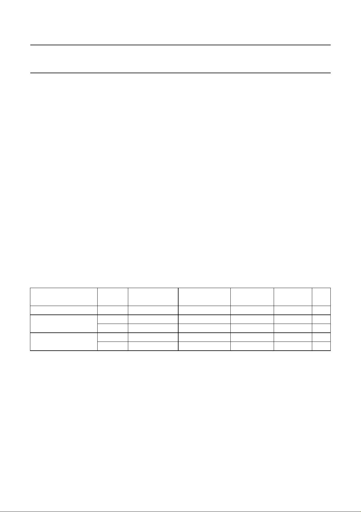
Table 1 Input frequencies and carrier ratios
DESCRIPTION SYMBOL B/G STANDARD M, N STANDARD L STANDARD
Picture/IF carrier f
Sound carrier f
pc
or f
SC1
f
SC2
Picture-to-sound carrier SC
SC
IF
1
2
38.9 45.75/58.75 38.9 33.9 MHz
33.4 41.25/54.25 32.4 40.4 MHz
33.158 −−−MHz
13 7 10 10 dB
20 −−−dB
L ACCENT
STANDARD
UNIT
1997 May 12 18
Page 19
Philips Semiconductors Preliminary specification
Single/multistandard VIF/SIF-PLL and
FM-PLL/AM demodulators
handbook, full pagewidth
V
i(VIF)(rms)
(mV)
0.6
70
gain
(dB)
600.06
50
40
30
206
10
060
−10
1.0 2.521.5 3 3.5 4
TDA9817; TDA9818
(1) (2) (3) (4)
V4 (V)
MHA665
4.5
0
1.0
2.0
I
tuner
(mA)
(1) I
; R
100
(mV)
10
0.1
TOP
1
=22kΩ.
(dBµV)
tuner
(2) Gain.
handbook, full pagewidth
V
i(SIF)(rms)
110
100
(3) I
; R
; R
TOP
TOP
=11kΩ.
=0Ω.
(4) I
tuner
tuner
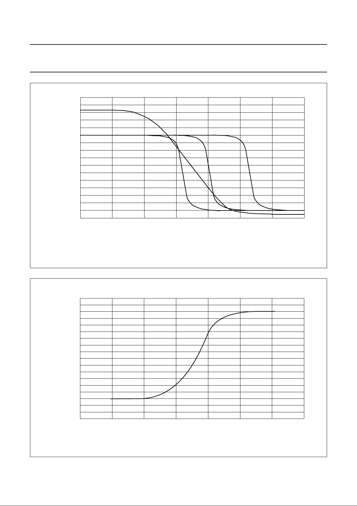
Fig.3 Typical VIF and tuner AGC characteristic.
MHA666
90
80
70
60
50
40
30
0.01
20
1.0 2.521.5 3 3.5 4
Fig.4 Typical SIF AGC characteristic (FM and AM mode).
1997 May 12 19
V5 (V)
4.5
Page 20
Philips Semiconductors Preliminary specification
Single/multistandard VIF/SIF-PLL and
FM-PLL/AM demodulators
70
handbook, halfpage
S/N
(dB)
60
50
40
30
20
10
0
60 40 20 20
TDA9817; TDA9818
MED684
0
V
600.06 0.6 6
V
10
i(IF)(rms)
i(IF)(rms)
(dB)
600
(mV)
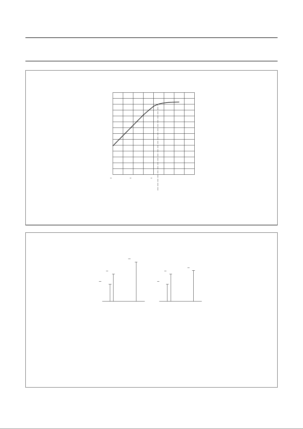
Fig.5 Typical signal-to-noise ratio as a function of IF input voltage.
handbook, halfpage
13.2 dB
27 dB
SC CC PC SC CC PC
SC = sound carrier, with respect to sync level.
CC = chrominance carrier, with respect to sync level.
PC = picture carrier, with respect to sync level.
The sound carrier levels are taking into account a sound shelf attenuation of 20 dB (SAW filter G1962).
3.2 dB
13.2 dB
27 dB
BLUE YELLOW
10 dB
MED685 - 1
Fig.6 Input signal conditions.
1997 May 12 20
Page 21
Philips Semiconductors Preliminary specification
Single/multistandard VIF/SIF-PLL and
FM-PLL/AM demodulators
handbook, full pagewidth
P
TDA9817
TDA9818
17
VP = 5 VV
I
17
22 kΩ V
22 kΩ
100
nF
AFC
V
AFC
(V)
2.5
I
17
(µA)
−200
−100
0
100
200
38.5 38.9 39.3
TDA9817; TDA9818
MHA667
(source current)
(sink current)
f (MHz)
handbook, full pagewidth
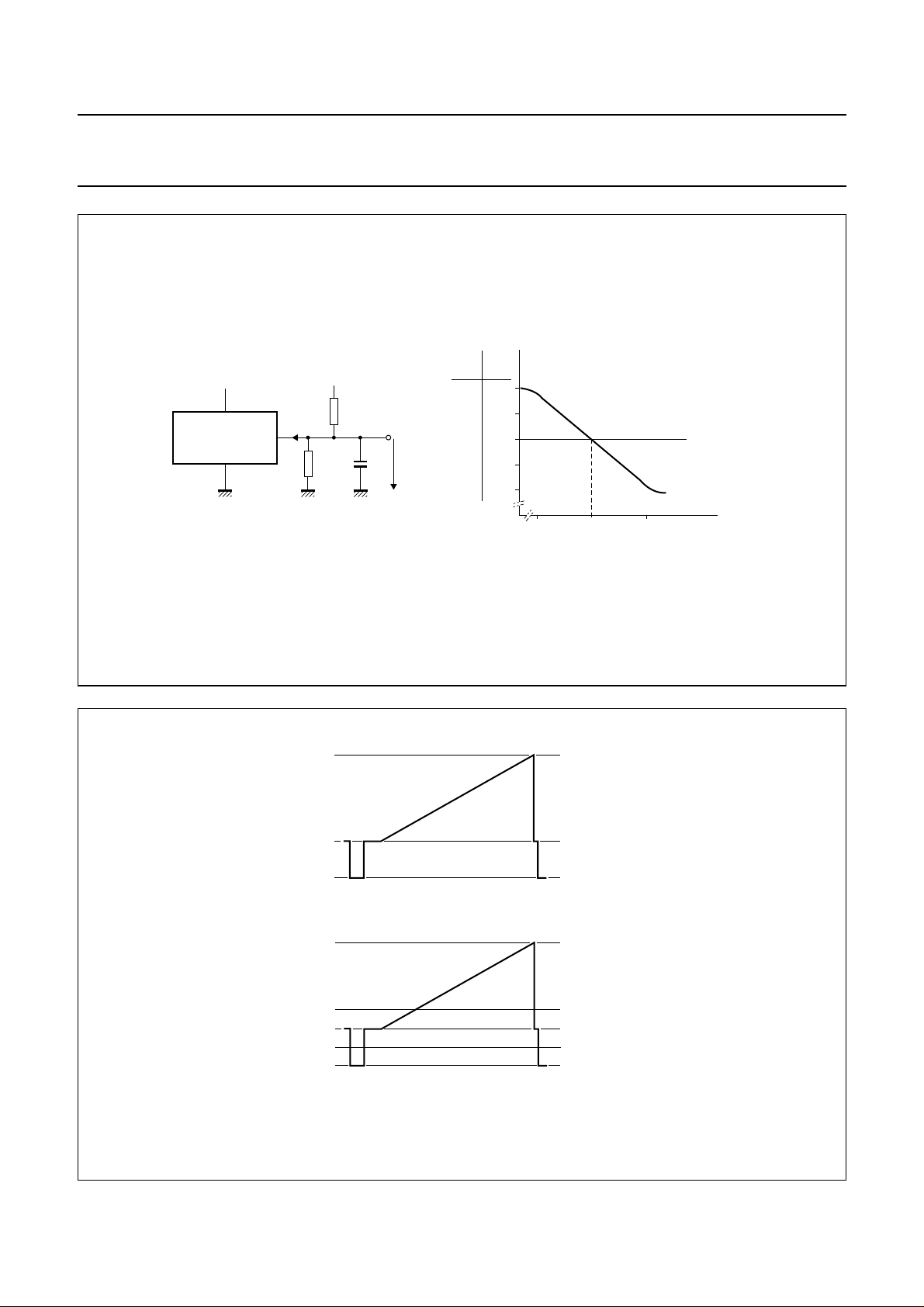
Fig.7 Measurement conditions and typical AFC characteristic.
2.6 V
1.83 V
1.5 V
standard B/G and M, N
2.6 V
2.0 V
1.83 V
1.66 V
1.5 V
standard L
white level
black level
sync level
white level
threshold level
black level
threshold level
sync level
MHA668
Fig.8 Typical video signal levels on output pin 16 (sound carrier off).
1997 May 12 21
Page 22
Philips Semiconductors Preliminary specification
Single/multistandard VIF/SIF-PLL and
FM-PLL/AM demodulators
10
(1) Signal.
(2) AM rejection.
(3) Noise.
handbook, halfpage
(dB)
−10
−30
−50
−70
30
(1)
(2)
(3)
50
MHA669
70 110
90
input voltage (dBµV)
TDA9817; TDA9818
(1) Signal.
(2) THD.
(3) Noise.
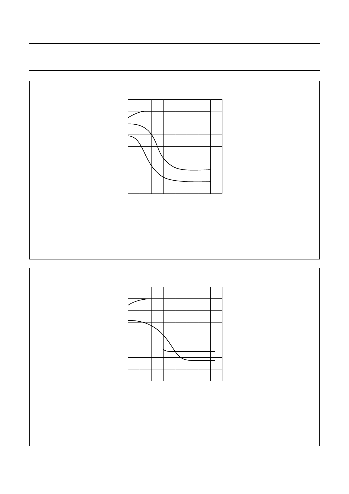
Fig.9 Typical audio level, noise and AM rejection (54% FM deviation) for FM.
10
handbook, halfpage
(dB)
−10
−30
−50
−70
30
(1)
(2)
(3)
50
70 110
input voltage (dBµV)
MHA670
1.6
THD
(%)
1.2
0.8
0.4
90
0
Fig.10 Typical audio level, noise and THD (54% AM modulation) for AM.
1997 May 12 22
Page 23
Philips Semiconductors Preliminary specification
Single/multistandard VIF/SIF-PLL and
FM-PLL/AM demodulators
handbook, full pagewidth
VP = 5 V
VP = 5 V
TDA9817
TDA9818
MHA671
TDA9817; TDA9818
100 mV
(f
= 70 Hz)
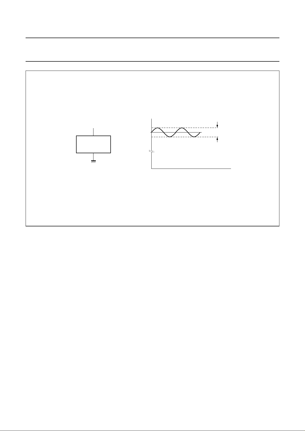
ripple
t
Fig.11 Ripple rejection condition.
1997 May 12 23
Page 24
Philips Semiconductors Preliminary specification
Single/multistandard VIF/SIF-PLL and
FM-PLL/AM demodulators
(dBµV)
140
120
100
(1)
80
tuning gain
control range
handbook, full pagewidth
antenna input
SAW insertion
loss 14 dB
IF slip
6 dB
TDA9817; TDA9818
10
video 1.1 V (p-p)
1
−1
10
IF signals
RMS value
(V)
−2
10
(TOP)
70 dB
VIF AGC
(1) Depends on TOP.
−3
MHA672
10
0.66 × 10
−4
10
−5
10
0.66 × 10
−3
−5
60
SAW insertion
loss 14 dB
40
40 dB
RF gain
20
10
VHF/UHF tuner VIF
tuner SAW filter
VIF amplifier, demodulator
and video
TDA9817; TDA9818
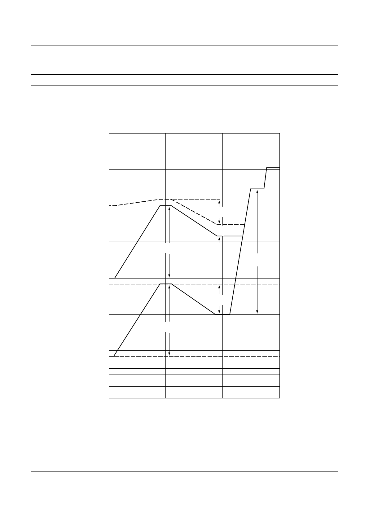
Fig.12 Front end level diagram.
1997 May 12 24
Page 25
Philips Semiconductors Preliminary specification
Single/multistandard VIF/SIF-PLL and
FM-PLL/AM demodulators
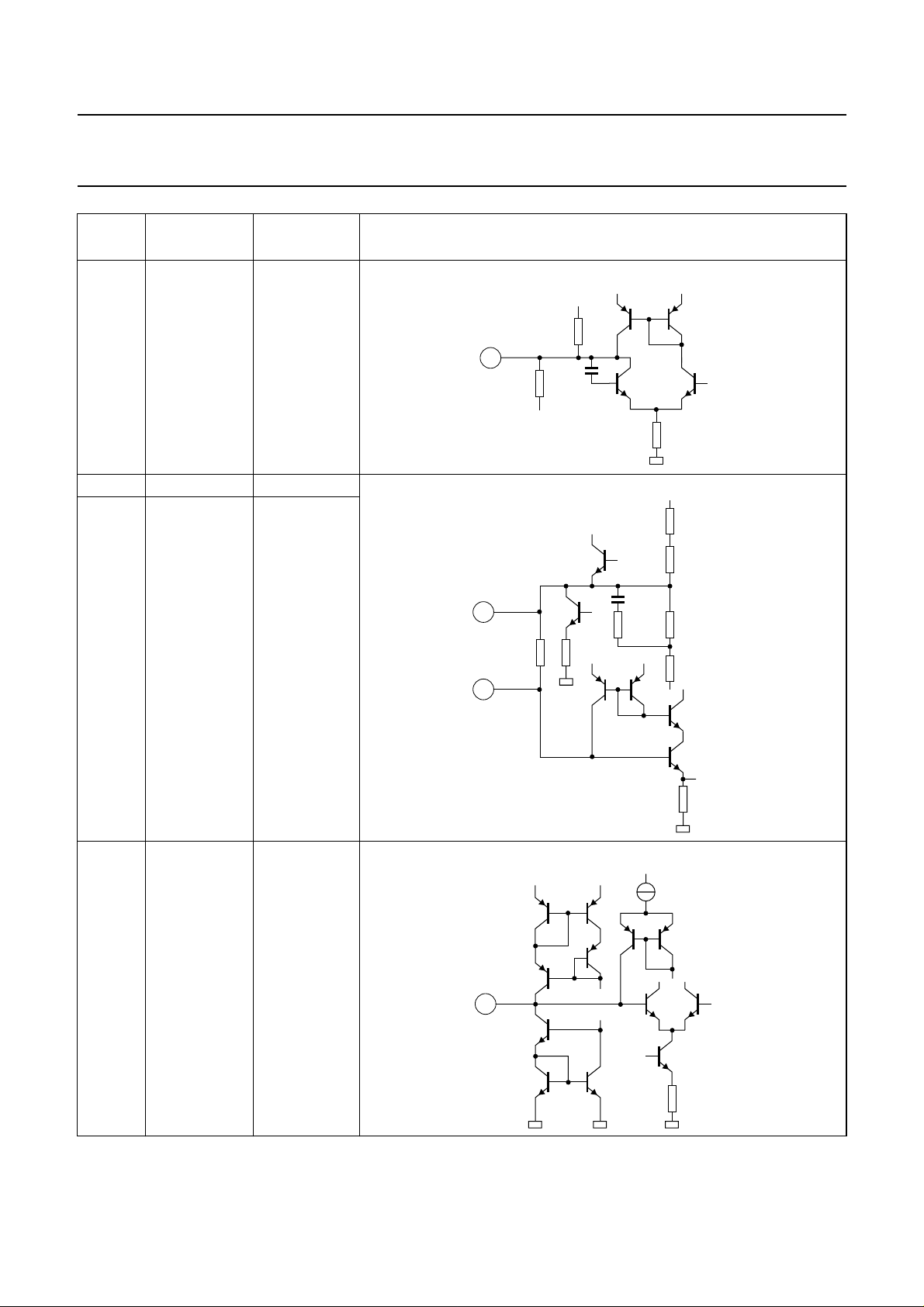
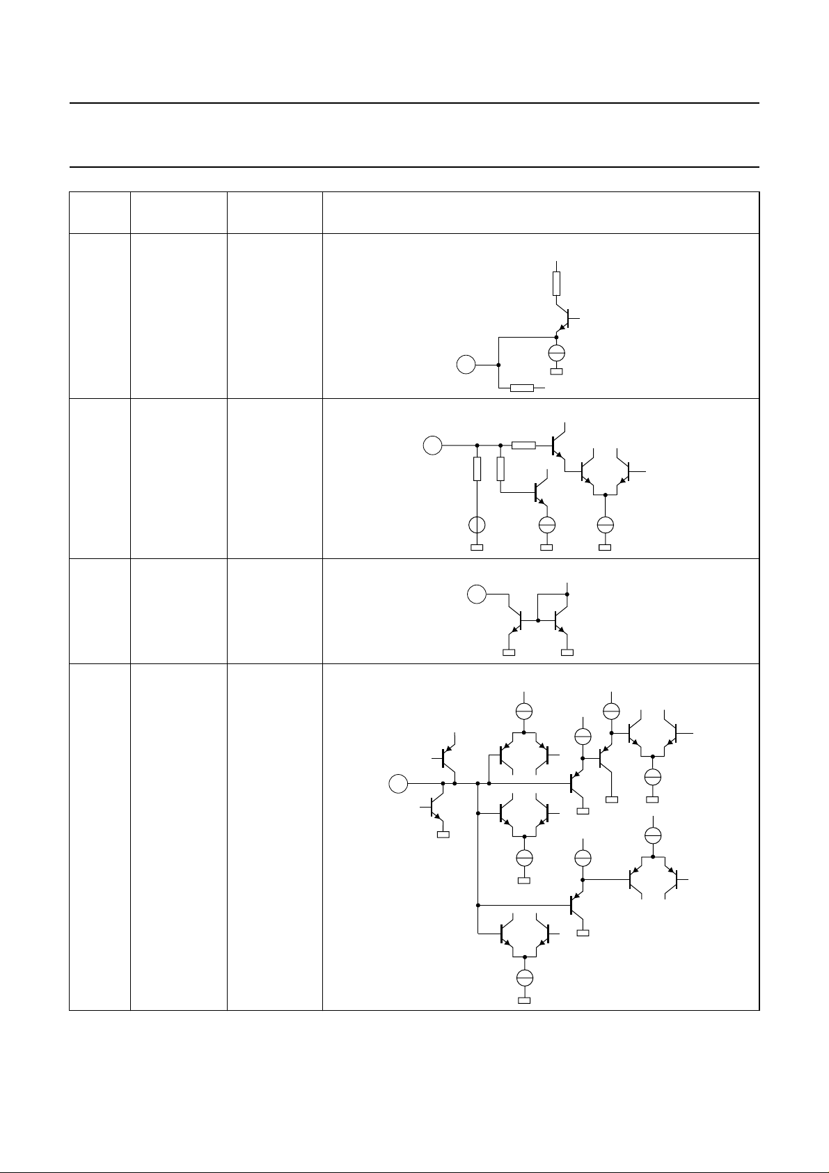
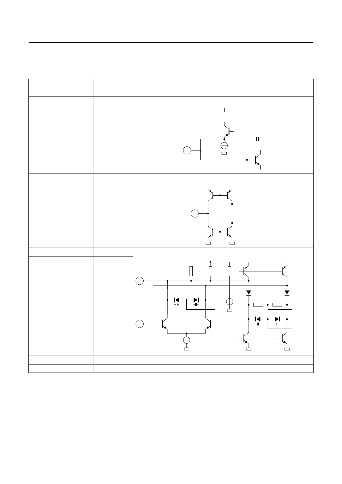
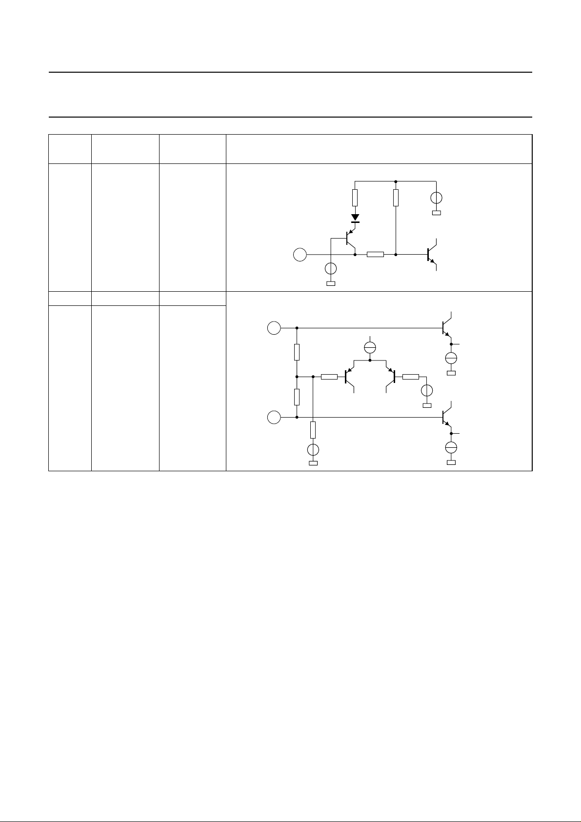
INTERNAL CIRCUITRY
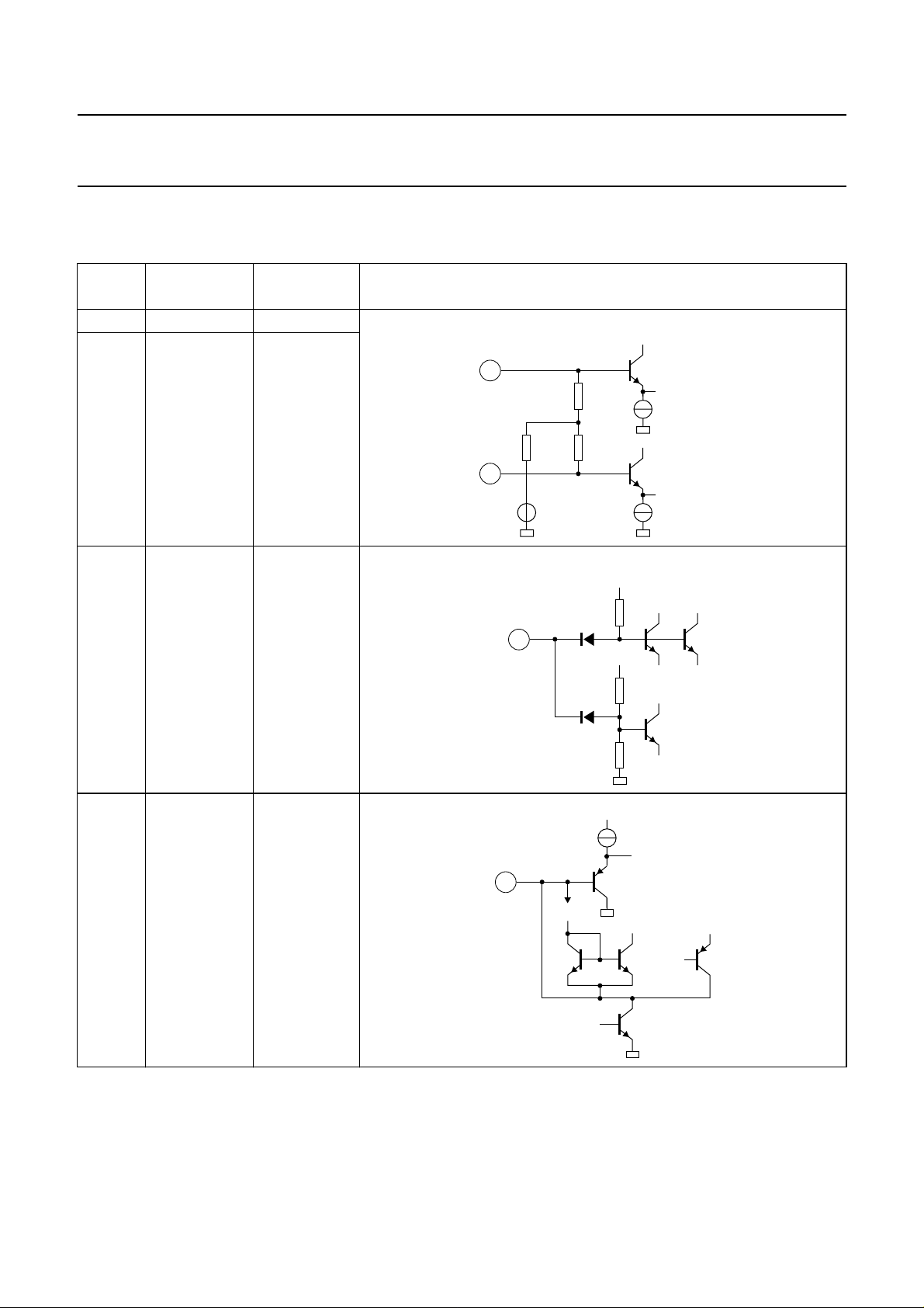
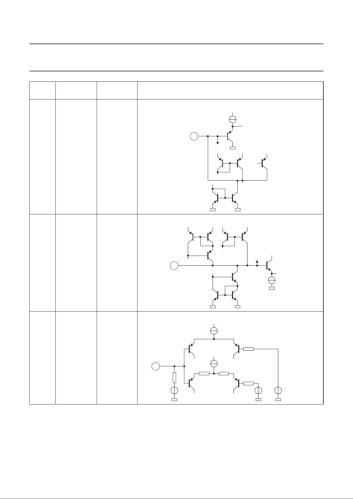
Table 2 Equivalent pin circuits and pin voltages
PIN
NO.
1V
2V
3 STD
PIN
SYMBOL
i VIF1
i VIF2
(1)
DC VOLTAGE
(V)
3.4
3.4
0toV
P
EQUIVALENT CIRCUIT (WITHOUT ESD PROTECTION CIRCUIT)
TDA9817; TDA9818
+
1
1.1 kΩ
1.1 kΩ800 Ω
2
3.4 V
3.6 V
650 µA
+
650 µA
MHA673
4C
VAGC
1.5 to 4.0
26 kΩ
3
3.6 V
16 kΩ
24 kΩ
MHA674
40 µA
4
I
b
1 mA
2.5 µA
0.3/20/40 µA
MHA675
1997 May 12 25
Page 26
Philips Semiconductors Preliminary specification
Single/multistandard VIF/SIF-PLL and
FM-PLL/AM demodulators
PIN
NO.
5C
6T
PIN
SYMBOL
SAGC
PLL
DC VOLTAGE
(V)
1.5 to 4.0
1.5 to 4.0
EQUIVALENT CIRCUIT (WITHOUT ESD PROTECTION CIRCUIT)
TDA9817; TDA9818
+
15 µA
5
I
b
+++
±1 µA
MHA676
++++
7 LADJ
(1)
0toV
I
+
b
6
VCO
200 µA
MHA677
P
+
100 µA
7.6 kΩ
+
7
9 kΩ 9 kΩ
17 kΩ
3.6 V
100 µA
7.2 kΩ
1 V
2.5 V
MHA678
1997 May 12 26
Page 27
Philips Semiconductors Preliminary specification
Single/multistandard VIF/SIF-PLL and
FM-PLL/AM demodulators
PIN
NO.
8V
9V
10 C
PIN
SYMBOL
oAF
de-em
de-em
DC VOLTAGE
(V)
2.3
2.3
2.3
EQUIVALENT CIRCUIT (WITHOUT ESD PROTECTION CIRCUIT)
TDA9817; TDA9818
++
21.7 kΩ
8
25 pF
23.7 kΩ
120 Ω
MHA679
5.6 kΩ
+
8.4 kΩ
11 C
DEC
1.2 to 3.0
9
10
11
10 pF
39 kΩ
290 Ω27.4 kΩ
++
8.4 kΩ
5.6 kΩ
+
3.5 kΩ
MHA680
+
90 µA
1997 May 12 27
1 kΩ
MHA681
Page 28
Philips Semiconductors Preliminary specification
Single/multistandard VIF/SIF-PLL and
FM-PLL/AM demodulators
PIN
NO.
12 V
13 V
14 TAGC 0 to 13.2
PIN
SYMBOL
o QSS
iFM
DC VOLTAGE
(V)
2.0
2.65
EQUIVALENT CIRCUIT (WITHOUT ESD PROTECTION CIRCUIT)
12
13
2.65 V 35 µA
14.7 kΩ
400 Ω
40 kΩ640 Ω
TDA9817; TDA9818
+
150 Ω
1.9 mA
MHA682
600 µA
MHA683
15 C
BL
(1)
0 to 3.2
14
MHA684
+
+
+
+
10 µA
10 µA
MHA685
+
5 µA
+
2.5 µA
15
30 µA
2.5 µA
0.15 µA
16 µA
2.5 µA
1997 May 12 28
Page 29
Philips Semiconductors Preliminary specification
Single/multistandard VIF/SIF-PLL and
FM-PLL/AM demodulators
PIN
NO.
16 V
17 AFC 0.3 to V
PIN
SYMBOL
o(vid)
DC VOLTAGE
(V)
sync level: 1.5
− 0.3
P
EQUIVALENT CIRCUIT (WITHOUT ESD PROTECTION CIRCUIT)
TDA9817; TDA9818
+
100 Ω
2.1 pF
16
++
17
3.0 mA
I
AFC
±200 µA
MHA686
18 VCO1 2.7
19 VCO2 2.7
20 GND 0
21 V
P
V
MHA687
++
420 Ω420 Ω
18
B/G
19
500 µA
P
50 Ω
2.8 V
20 kΩ
20 kΩ
L accent
MHA688
1997 May 12 29
Page 30
Philips Semiconductors Preliminary specification
Single/multistandard VIF/SIF-PLL and
FM-PLL/AM demodulators
PIN
NO.
22 TADJ (TOP) 0 to 1.9
23 V
24 V
PIN
SYMBOL
i SIF1
i SIF2
DC VOLTAGE
(V)
3.4
3.4
EQUIVALENT CIRCUIT (WITHOUT ESD PROTECTION CIRCUIT)
23
1.1 kΩ
TDA9817; TDA9818
30 kΩ
22
5 kΩ
9 kΩ
1.9 V
20 kΩ 3.6 V
MHA689
+
+
100 µA
400 µA
10 kΩ
Note
1. Not connected for TDA9817.
1.1 kΩ
24
800 Ω
3.4 V
1.8 V
+
400 µA
MHA690
1997 May 12 30
Page 31
Philips Semiconductors Preliminary specification
Single/multistandard VIF/SIF-PLL and
FM-PLL/AM demodulators
TEST AND APPLICATION INFORMATION
5.6 kΩ
10 nF
13
14
tuner AGC
nF
AFC
P
V
100
video
1.1 V (p-p)
22 kΩ
(1)
100 nF
22 kΩ
GND
10 nF
TOP
(2)
15
BL
C
17 16
19
22
kΩ
2223 1821 20
mute
switch
(2)
TDA9817
TDA9818
(2)
QSS
intercarrier
output
x
R
2.4
AF
330
kΩ
output
22
kΩ
Ω
2.2
2.2
560 Ω
µF
µF
12
8 9 10 11
7
3
2456
22
µF
DEC
C
22 nF
220
(3)
5.5 MHz
nF
TDA9817; TDA9818
MHA691
≈50 µs
de-emphasis
switch
L/L accent
and adjust
loop
filter
SIF
AGC
VIF
AGC
switch
selection
standards
handbook, full pagewidth
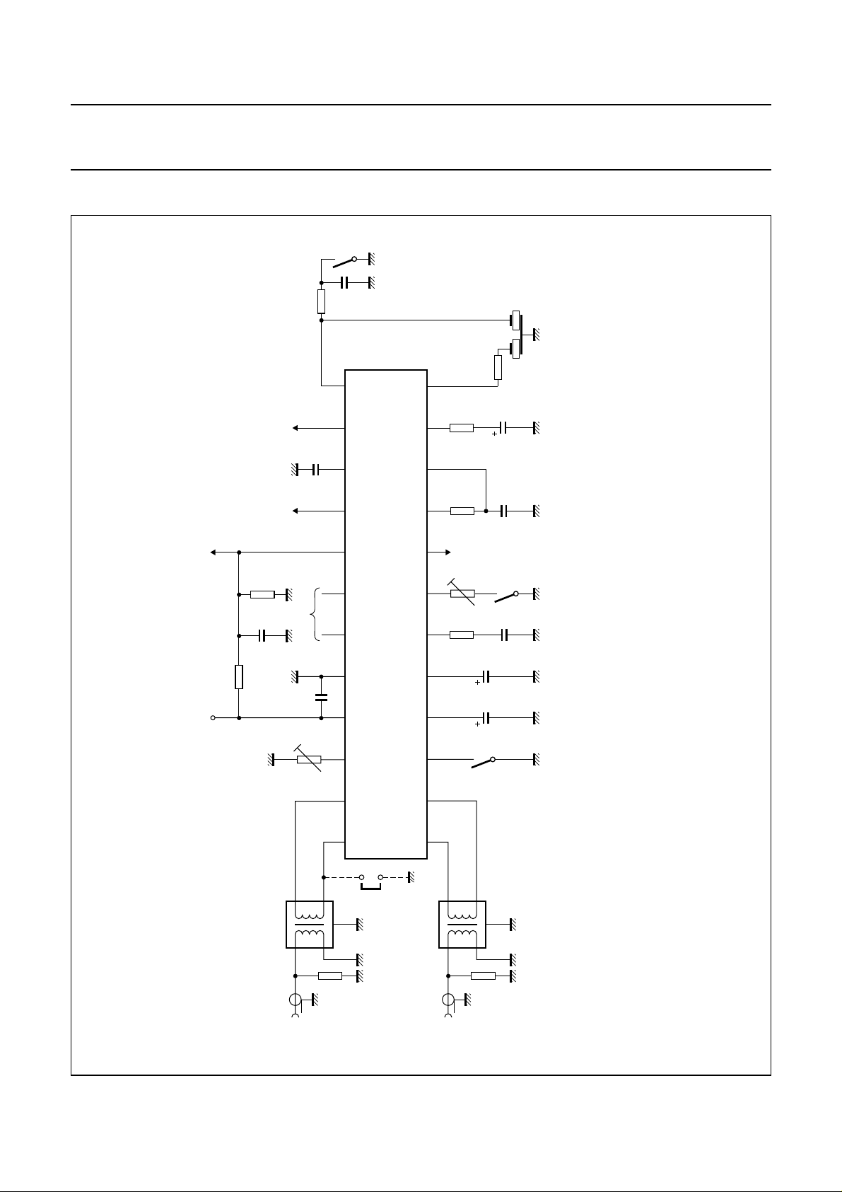
Fig.13 Test circuit.
24
5
4
1:1
1
SIF
input
3
2
Ω
50
mode
intercarrier
1997 May 12 31
1
5
4
input
3
2
Ω
50
(1) See Table 3.
(2) Not connected for TDA9817.
(3) Depends on TV standard.
1:1
1
VIF
Page 32
Philips Semiconductors Preliminary specification
Single/multistandard VIF/SIF-PLL and
FM-PLL/AM demodulators
mute
switch
5.6 kΩ
10 nF
(2)
TDA9817
TDA9818
(2)
12
8 9 10 11
7
3
2456
video
1 V (p-p)
AFC
P
V
13
14
tuner AGC
nF
100
15
µH
22 kΩ
(1)
100 nF
22 kΩ
GND
10 nF
TOP
330
22
(2)
15
BL
C
Ω
17 16
19
kΩ
2223 1821 20
QSS
intercarrier
output
x
R
2.4
AF
330
kΩ
output
22
Ω
TDA9817; TDA9818
(3)
MHA692
5.5 MHz
560 Ω
22
µF
DEC
C
22 nF
≈50 µs
de-emphasis
kΩ
switch
L/L accent
and adjust
loop
filter
SIF
AGC
VIF
AGC
switch
selection
standards
handbook, full pagewidth
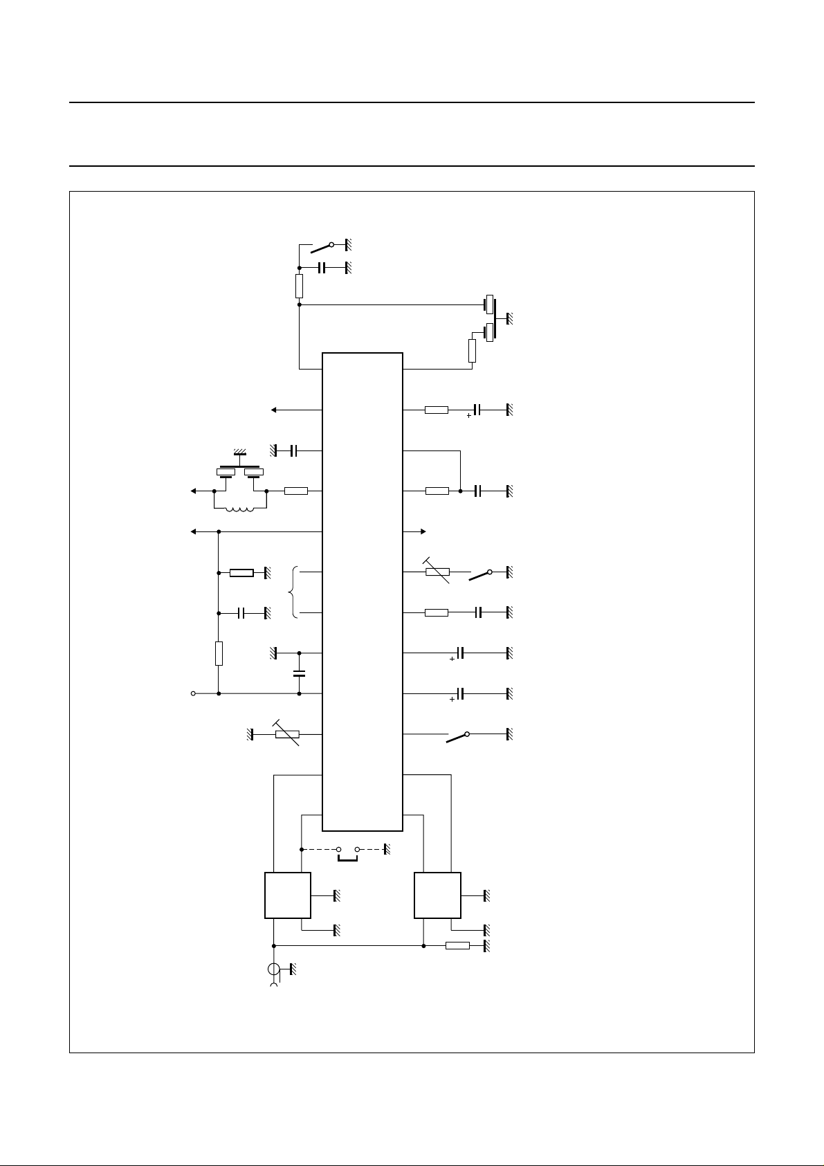
Fig.14 Application circuit.
2.2
2.2
nF
220
µF
µF
SIF
1
mode
intercarrier
IF
SAW
input
K9453
FILTER
24
(3)
1997 May 12 32
VIF
SAW
K3953
FILTER
50
(3)
Ω
(1) See Table 3.
(2) Not connected for TDA9817.
(3) Depends on TV standard.
Page 33
Philips Semiconductors Preliminary specification
Single/multistandard VIF/SIF-PLL and
TDA9817; TDA9818
FM-PLL/AM demodulators
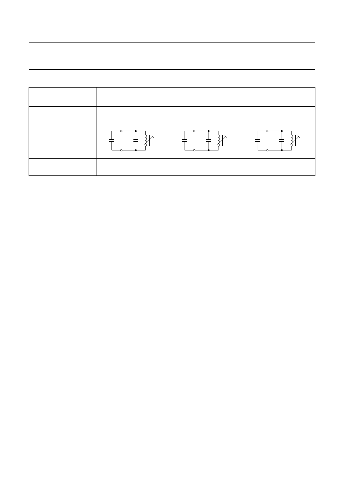
Table 3 Oscillator circuit for the different TV standards
PARAMETER EUROPE USA JAPAN
IF frequency 38.9 MHz 45.75 MHz 58.75 MHz
VCO frequency 77.8 MHz 91.5 MHz 117.5 MHz
Oscillator circuit
18
C
VCO
8.5 pF
C(C9)
8.2 pF
19
L(F4)
251 nH
MHA693
C
VCO
8.5 pF
e.g. Toko coil 5KM 369SNS-2010Z 5KMC V369SCS-2370Z MC139 NE545SNAS100108
Philips ceramic capacitor 2222 632 51828 inside of coil 15 pF SMD; size = 0805
18
19
C(C9)
10 pF
L(F4)
163 nH
MHA694
C
VCO
8.5 pF
18
C(C9)
19
15 pF
L(F4)
78 nH
MHA695
1997 May 12 33
Page 34
Philips Semiconductors Preliminary specification
Single/multistandard VIF/SIF-PLL and
FM-PLL/AM demodulators
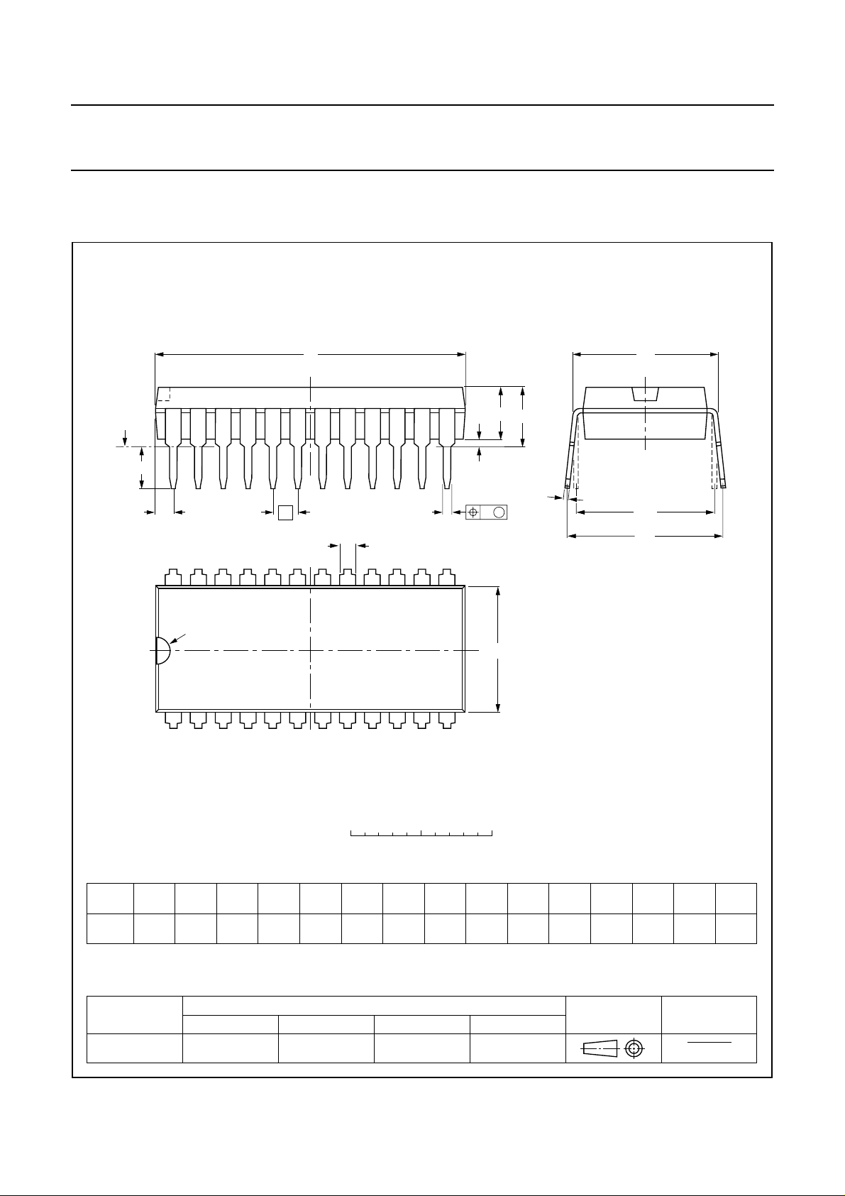
PACKAGE OUTLINE
SDIP24: plastic shrink dual in-line package; 24 leads (400 mil)
D
seating plane
L
Z
24
e
b
b
1
13
TDA9817; TDA9818
SOT234-1
M
E
A
2
A
A
1
w M
c
(e )
M
1
H
pin 1 index
1
0 5 10 mm
scale
DIMENSIONS (mm are the original dimensions)
A
A
A
UNIT b
Note
1. Plastic or metal protrusions of 0.25 mm maximum per side are not included.
mm
OUTLINE
VERSION
SOT234-1
max.
4.7 0.51 3.8
12
min.
max.
IEC JEDEC EIAJ
1.3
0.8
b
1
0.53
0.40
REFERENCES
0.32
0.23
cEe M
(1) (1)
D
22.3
21.4
9.1
8.7
E
12
(1)
Z
L
e
1
3.2
2.8
M
E
10.7
10.2
EUROPEAN
PROJECTION
12.2
10.5
w
H
0.181.778 10.16
ISSUE DATE
92-11-17
95-02-04
max.
1.6
1997 May 12 34
Page 35
Philips Semiconductors Preliminary specification
Single/multistandard VIF/SIF-PLL and
FM-PLL/AM demodulators
SOLDERING
Introduction
There is no soldering method that is ideal for all IC
packages. Wave soldering is often preferred when
through-hole and surface mounted components are mixed
on one printed-circuit board. However, wave soldering is
not always suitable for surface mounted ICs, or for
printed-circuits with high population densities. In these
situations reflow soldering is often used.
This text gives a very brief insight to a complex technology.
A more in-depth account of soldering ICs can be found in
our
“IC Package Databook”
Soldering by dipping or by wave
The maximum permissible temperature of the solder is
260 °C; solder at this temperature must not be in contact
with the joint for more than 5 seconds. The total contact
time of successive solder waves must not exceed
5 seconds.
(order code 9398 652 90011).
TDA9817; TDA9818
The device may be mounted up to the seating plane, but
the temperature of the plastic body must not exceed the
specified maximum storage temperature (T
printed-circuit board has been pre-heated, forced cooling
may be necessary immediately after soldering to keep the
temperature within the permissible limit.
Repairing soldered joints
Apply a low voltage soldering iron (less than 24 V) to the
lead(s) of the package, below the seating plane or not
more than 2 mm above it. If the temperature of the
soldering iron bit is less than 300 °C it may remain in
contact for up to 10 seconds. If the bit temperature is
between 300 and 400 °C, contact may be up to 5 seconds.
stg max
). If the
DEFINITIONS
Data sheet status
Objective specification This data sheet contains target or goal specifications for product development.
Preliminary specification This data sheet contains preliminary data; supplementary data may be published later.
Product specification This data sheet contains final product specifications.
Limiting values
Limiting values given are in accordance with the Absolute Maximum Rating System (IEC 134). Stress above one or
more of the limiting values may cause permanent damage to the device. These are stress ratings only and operation
of the device at these or at any other conditions above those given in the Characteristics sections of the specification
is not implied. Exposure to limiting values for extended periods may affect device reliability.
Application information
Where application information is given, it is advisory and does not form part of the specification.
LIFE SUPPORT APPLICATIONS
These products are not designed for use in life support appliances, devices, or systems where malfunction of these
products can reasonably be expected to result in personal injury. Philips customers using or selling these products for
use in such applications do so at their own risk and agree to fully indemnify Philips for any damages resulting from such
improper use or sale.
1997 May 12 35
Page 36

Philips Semiconductors – a worldwide company
Argentina: see South America
Australia: 34 Waterloo Road, NORTH RYDE, NSW 2113,
Tel. +61 2 9805 4455, Fax. +61 2 9805 4466
Austria: Computerstr. 6, A-1101 WIEN, P.O. Box 213,
Tel. +43 1 60 101, Fax. +43 1 60 101 1210
Belarus: Hotel Minsk Business Center, Bld. 3, r. 1211, Volodarski Str. 6,
220050 MINSK, Tel. +375 172 200 733, Fax. +375 172 200 773
Belgium: see The Netherlands
Brazil: see South America
Bulgaria: Philips Bulgaria Ltd., Energoproject, 15th floor,
51 James Bourchier Blvd., 1407 SOFIA,
Tel. +359 2 689 211, Fax. +359 2 689 102
Canada: PHILIPS SEMICONDUCTORS/COMPONENTS,
Tel. +1 800 234 7381
China/Hong Kong: 501 Hong Kong Industrial Technology Centre,
72 Tat Chee Avenue, Kowloon Tong, HONG KONG,
Tel. +852 2319 7888, Fax. +852 2319 7700
Colombia: see South America
Czech Republic: see Austria
Denmark: Prags Boulevard 80, PB 1919, DK-2300 COPENHAGEN S,
Tel. +45 32 88 2636, Fax. +45 31 57 0044
Finland: Sinikalliontie 3, FIN-02630 ESPOO,
Tel. +358 9 615800, Fax. +358 9 61580920
France: 4 Rue du Port-aux-Vins, BP317, 92156 SURESNES Cedex,
Tel. +33 1 40 99 6161, Fax. +33 1 40 99 6427
Germany: Hammerbrookstraße 69, D-20097 HAMBURG,
Tel. +49 40 23 53 60, Fax. +49 40 23 536 300
Greece: No. 15, 25th March Street, GR 17778 TAVROS/ATHENS,
Tel. +30 1 4894 339/239, Fax. +30 1 4814 240
Hungary: see Austria
India: Philips INDIA Ltd, Shivsagar Estate, A Block, Dr. Annie Besant Rd.
Worli, MUMBAI 400 018, Tel. +91 22 4938 541, Fax. +91 22 4938 722
Indonesia: see Singapore
Ireland: Newstead, Clonskeagh, DUBLIN 14,
Tel. +353 1 7640 000, Fax. +353 1 7640 200
Israel: RAPAC Electronics, 7 Kehilat Saloniki St, PO Box 18053,
TEL AVIV 61180, Tel. +972 3 645 0444, Fax. +972 3 649 1007
Italy: PHILIPS SEMICONDUCTORS, Piazza IV Novembre 3,
20124 MILANO, Tel. +39 2 6752 2531, Fax. +39 2 6752 2557
Japan: Philips Bldg 13-37, Kohnan 2-chome, Minato-ku, TOKYO 108,
Tel. +81 3 3740 5130, Fax. +81 3 3740 5077
Korea: Philips House, 260-199 Itaewon-dong, Yongsan-ku, SEOUL,
Tel. +82 2 709 1412, Fax. +82 2 709 1415
Malaysia: No. 76 Jalan Universiti, 46200 PETALING JAYA, SELANGOR,
Tel. +60 3 750 5214, Fax. +60 3 757 4880
Mexico: 5900 Gateway East, Suite 200, EL PASO, TEXAS 79905,
Tel. +9-5 800 234 7381
Middle East: see Italy
Netherlands: Postbus 90050, 5600 PB EINDHOVEN, Bldg. VB,
Tel. +31 40 27 82785, Fax. +31 40 27 88399
New Zealand: 2 Wagener Place, C.P.O. Box 1041, AUCKLAND,
Tel. +64 9 849 4160, Fax. +64 9 849 7811
Norway: Box 1, Manglerud 0612, OSLO,
Tel. +47 22 74 8000, Fax. +47 22 74 8341
Philippines: Philips Semiconductors Philippines Inc.,
106 Valero St. Salcedo Village, P.O. Box 2108 MCC, MAKATI,
Metro MANILA, Tel. +63 2 816 6380, Fax. +63 2 817 3474
Poland: Ul. Lukiska 10, PL 04-123 WARSZAWA,
Tel. +48 22 612 2831, Fax. +48 22 612 2327
Portugal: see Spain
Romania: see Italy
Russia: Philips Russia, Ul. Usatcheva 35A, 119048 MOSCOW,
Tel. +7 095 755 6918, Fax. +7 095 755 6919
Singapore: Lorong 1, Toa Payoh, SINGAPORE 1231,
Tel. +65 350 2538, Fax. +65 251 6500
Slovakia: see Austria
Slovenia: see Italy
South Africa: S.A. PHILIPS Pty Ltd., 195-215 Main Road Martindale,
2092 JOHANNESBURG, P.O. Box 7430 Johannesburg 2000,
Tel. +27 11 470 5911, Fax. +27 11 470 5494
South America: Rua do Rocio 220, 5th floor, Suite 51,
04552-903 São Paulo, SÃO PAULO - SP, Brazil,
Tel. +55 11 821 2333, Fax. +55 11 829 1849
Spain: Balmes 22, 08007 BARCELONA,
Tel. +34 3 301 6312, Fax. +34 3 301 4107
Sweden: Kottbygatan 7, Akalla, S-16485 STOCKHOLM,
Tel. +46 8 632 2000, Fax. +46 8 632 2745
Switzerland: Allmendstrasse 140, CH-8027 ZÜRICH,
Tel. +41 1 488 2686, Fax. +41 1 481 7730
Taiwan: Philips Semiconductors, 6F, No. 96, Chien Kuo N. Rd., Sec. 1,
TAIPEI, Taiwan Tel. +886 2 2134 2865, Fax. +886 2 2134 2874
Thailand: PHILIPS ELECTRONICS (THAILAND) Ltd.,
209/2 Sanpavuth-Bangna Road Prakanong, BANGKOK 10260,
Tel. +66 2 745 4090, Fax. +66 2 398 0793
Turkey: Talatpasa Cad. No. 5, 80640 GÜLTEPE/ISTANBUL,
Tel. +90 212 279 2770, Fax. +90 212 282 6707
Ukraine: PHILIPS UKRAINE, 4 Patrice Lumumba str., Building B, Floor 7,
252042 KIEV, Tel. +380 44 264 2776, Fax. +380 44 268 0461
United Kingdom: Philips Semiconductors Ltd., 276 Bath Road, Hayes,
MIDDLESEX UB3 5BX, Tel. +44 181 730 5000, Fax. +44 181 754 8421
United States: 811 East Arques Avenue, SUNNYVALE, CA 94088-3409,
Tel. +1 800 234 7381
Uruguay: see South America
Vietnam: see Singapore
Yugoslavia: PHILIPS, Trg N. Pasica 5/v, 11000 BEOGRAD,
Tel. +381 11 625 344, Fax.+381 11 635 777
For all other countries apply to: Philips Semiconductors, Marketing & Sales Communications,
Building BE-p, P.O. Box 218, 5600 MD EINDHOVEN, The Netherlands, Fax. +31 40 27 24825
© Philips Electronics N.V. 1997 SCA54
All rights are reserved. Reproduction in whole or in part is prohibited without the prior written consent of the copyright owner.
The information presented in this document does not form part of any quotation or contract, is believed to be accurate and reliable and may be changed
without notice. No liability will be accepted by the publisher for any consequence of its use. Publication thereof does not convey nor imply any license
under patent- or other industrial or intellectual property rights.
Internet: http://www.semiconductors.philips.com
Printed in The Netherlands 547047/1200/01/pp36 Date of release: 1997 May 12 Document order number: 9397 750 01648
 Loading...