

Page 1

Philips Semiconductors Preliminary specification
YUV picture improvement processor based
on histogram modification
FEATURES
• Picture content dependent non-linear Y and U, V
processing by histogram analysis
• Adaptive and variable gamma correction controls
• Black and white stretch capabilities
• Transparent I2C-bus control
• On-chip window generator for valid histogram
measurement and black detection.
GENERAL DESCRIPTION
The TDA9170 is a transparent analog video processor
with a YUV interface. It offers three main luminance
processing functions any combination of which can be
selected.
The luminance transfer is controlled in a non-linear
manner by the distribution (in 5 discrete histogram
sections) of the luminance values measured in a picture.
As a result, the contrast ratio of the most important parts of
the picture will be improved.
ORDERING INFORMATION
TYPE NUMBER
TDA9170 SDIP32 plastic shrink in-line package; 32 leads (400 mil) SOT232-1
NAME DESCRIPTION VERSION
Black restoration is available in the event of a set-up in the
luminance signal. A variable gamma function, after the
histogram conversion, offers the possibility of excellent
brightness control.
To maintain a proper colour reproduction, the saturation of
the U and V colour difference signals are controlled as a
function of the actual non-linearity in the luminance
channel.
The TDA9170 concept has maximum flexibility with the
optional on-board I
select) and window control. The supply voltage is 8 V. The
device is mounted in a 32 pin SDIP envelope.
PACKAGE
2
C-bus (including hardwired address
TDA9170
October 1994 2
Page 2
Philips Semiconductors Preliminary specification
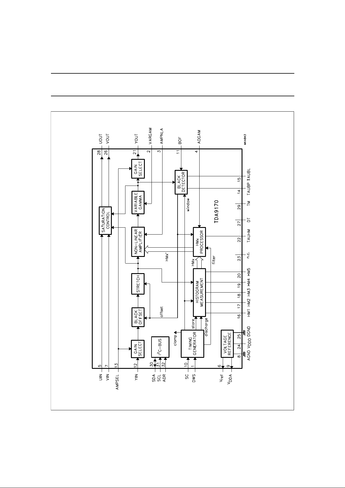
Fig.1 Block diagram.
YUV picture improvement processor based
on histogram modification
BLOCK DIAGRAM
TDA9170
October 1994 3
Page 3
Philips Semiconductors Preliminary specification
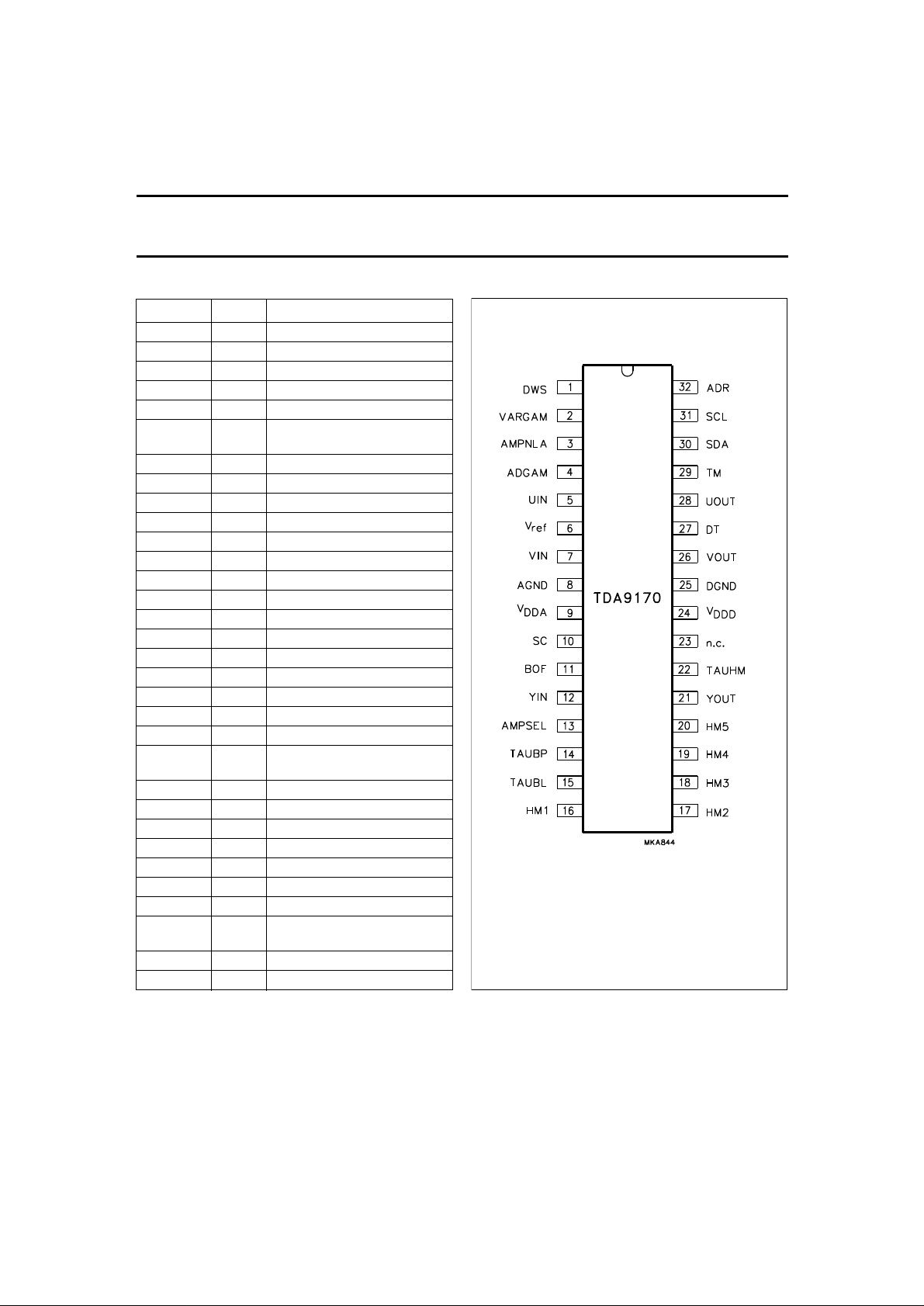
Fig.2 Pin configuration.
YUV picture improvement processor based
on histogram modification
PINNING
SYMBOL PIN DESCRIPTION
DWS 1 default window select input
VARGAM 2 variable gamma input
AMPNLA 3 amplitude non-linearity input
ADGAM 4 adaptive gamma input
UIN 5 colour difference U input
V
ref
VIN 7 colour difference V input
AGND 8 analog ground
V
DDA
SC 10 sandcastle input
BOF 11 black offset on/off input
YIN 12 luminance input
AMPSEL 13 amplitude select input
TAUBP 14 time constant black peak
TAUBL 15 time constant black loop
HM1 16 histogram segment memory 1
HM2 17 histogram segment memory 2
HM3 18 histogram segment memory 3
HM4 19 histogram segment memory 4
HM5 20 histogram segment memory 5
YOUT 21 luminance output
TAUHM 22 time constant histogram
n.c. 23 not connected
V
DDD
DGND 25 digital ground
VOUT 26 colour difference V output
DT 27 test option
UOUT 28 colour difference U output
TM 29 test option
SDA 30 serial data input/output
SCL 31 serial clock input (I2C-bus)
ADR 32 address select input (I2C-bus)
6 reference supply voltage output
(+4 V)
9 analog supply voltage
measurement loop
24 digital supply voltage (+5 V)
(I2C-bus)
TDA9170
October 1994 4
Page 4

Philips Semiconductors Preliminary specification
YUV picture improvement processor based
on histogram modification
FUNCTIONAL DESCRIPTION
Y input selection and amplification
The dynamic range of the luminance input amplifier can be
switched between 0.3 and 1 V (excluding sync) either
externally (pin AMPSEL) or by I2C-bus (AMPSEL bit).
Amplitudes that exceed the corresponding specified range
(e.g. the sync) will be clipped internally. The input is
clamped during the logic HIGH period of the clamp which
is defined by the sandcastle reference and should be
DC-decoupled with an external capacitor.
Black offset detection and correction
The black detector measures and stores the blackest part
of the picture within a defined window in each field. Any
difference between this value and the value measured
during the black clamp period is regarded as black offset.
In a closed loop configuration, the black offset is held until
a predefined value of the full scale (FS) value is fed back
to the input stage where it is partly compensated for.
Depending on the loop gain, 30% to 50% of the offset
value is counteracted. The loop gain is also a function of
the adaptive and variable gamma settings. The black
offset correction mechanism can be switched on and off by
2
the I
C-bus via the BON bit (see Table 6), or externally with
the black offset on/off switch (BOF pin 11).
Two external time constants are required to ensure correct
performance of the black detector; a loop filter time
constant (TAUBL) for the loop dynamics and a time
constant for memorizing the darkest parts of the picture
(TAUBP) in just one field. During the field retrace the time
constant TAUBP is first sampled and then preset to a value
that corresponds to the maximum black offset.
The corrected black offset is related to the nominal signal
amplitude which is reset to 100% FS via an amplitude
stretch function. Luminance values beyond FS are not
affected. Additionally, this offset is also used to set the
adaptive gain (see Section “Adaptive gamma”).
Histogram measurement
The histogram distribution is measured in real time over
five segments (HM1 to HM5) within a defined window
period of each field. During the window period, the video is
in one segment, a corresponding external capacitor C
is loaded via a current source. At the end of the field five
segment voltages are stored from the external capacitors
into on-board memories. The external capacitors are
discharged and the measurements are restarted.
HMx
TDA9170
Any part of the picture that does not contribute to the
information within the total picture should be omitted from
the histogram measurement. The miscount detector
disables measurements until it detects changing parts.
Additionally, luminance values close to FS (or white) do
not contribute sufficiently in order to maintain the absolute
light output. This procedure is allowed because the eye is
less sensitive to details in white.
As the miscount detector shortens the effective
measurement period and, because of spreads of internal
and external components, the current source is controlled
within in a closed loop so as to maintain a constant
average value of the sum of the segment voltages. The
dominant time constant of the closed loop is external and
can be tuned with an appropriate capacitor connected to
TAUHM (pin 22).
Processing of the measured histogram values
FIELD AVERAGING OF HISTOGRAM VALUES
With very rapid picture changes, also related to the field
interlace, flicker might result. The histogram values are
averaged at the field rate to reduce these flicker effects.
The time constant of the averaging process is adapted to
the speed of the histogram changes.
ADAPTIVE GAMMA
The output voltage of the first segment is fed to a variable
gain amplifier with a gain between 1 and 3. In this way
luminance values in the ‘black’ segment have a larger
weight. In our perception black parts are expanded, as
occurs with gamma control. However, the effective
contribution to the non-linear gain is only relevant for
moderate segment voltages and hence the term adaptive
gamma.
The adaptive gamma gain is amax-function of a fixed gain
part and a dynamic gain part. The fixed gain part can be
set externally with the adaptive gamma gain control
(ADGAM) or via the I2C-bus.
The dynamic part of the adaptive gamma gain is controlled
by the measured black offset value from the black
detector.
October 1994 5
Page 5

Philips Semiconductors Preliminary specification
YUV picture improvement processor based
on histogram modification
ADAPTIVE WHITE-POINT STRETCHING
For dominant HM4 and HM5 voltages or large white parts
the histogram conversion procedure makes a transfer with
large gain in the white parts. However, the amount of light
being emitted from the picture is considerably reduced.
The white stretcher introduces additional overall gain for
increased light production and, as a result, violates the
principle of having a full-scale reference.
S
TANDARD DEVIATION
For pictures in which segments of the histogram
distribution are very dominant, with respect to the others,
the non-linear amplification should be reduced to
compensate for pictures with a flat histogram distribution.
The standard deviation detector measures the spread of
the histogram distribution in the segments HM1 to HM5
and modulates the user setting of the non-linear amplifier.
Non-linear amplifier
The stored segment voltages, relative to their average
value and averaged over two fields, determine the
individual gain of each segment in such a way that
continuity is guaranteed for the complete range. The
maximum and minimum gain of each segment is limited.
Apart from the adaptive white-point stretching the black
and white references are not affected by the non-linear
processing. The amount of linearity can be controlled
externally at AMPNLA (pin 3) or via the I2C-bus.
Variable gamma function
As well as the histogram conversion, a variable gamma
function can be applied to ensure excellent brightness
control. It is intended as an alternative to the DC-offset of
the classic brightness user control; it maintains the black
and white references. The gamma ranges from 0.5 to 1.5.
The gamma can be set externally at VARGAM (pin 2) or
via the I2C-bus.
TDA9170
Timing generator
The TDA9170 is equipped with a transparent internal
timing generator for window purposes. As a timing
reference the relevant sandcastle (SC) can be used. The
window enables the black measurement and the
histogram measurement circuitry. The internal timing
generator is basically intended for system invariant
operation. The default window handles all existing norms
and disables measurement in subtitles or logos. This
default window is preset at power-up and can be selected
with a logic HIGH level at the default window select DWS
(pin 1). If not selected the blanking of the sandcastle will
define the window borders.
2
However, using the I
control bits (see Table 3), the window format can also be
user-programmed. The horizontal window generator
synchronizes on the rising edge of the burst key/clamp key
of the external sandcastle reference with an adjustable
window start and stop delay. The vertical window
generator synchronizes on the falling edge of the first burst
key/clamp key after a field pulse recognition.
I2C-bus specification
The I2C-bus is designed for transparent use. At power-up
all registers are preset for system invariant and external
control. All pins related to the I2C-bus can be left
open-circuit when the I2C-bus is in the standby mode. If
the sleep mode bit in the control register is set all settings
are left to bus control. For the relevant registers and
addresses see Tables 2 to 8.
C-bus and setting the WD1 and WD2
Colour compensation
Non-linear luminance processing influences the colour
reproduction, mainly the colour saturation. Therefore, U
and V signals are also processed for saturation
compensation. The U and V input signals are clamped
during the logic HIGH period of the clamp which is defined
by the sandcastle reference and should be DC decoupled
with external capacitors.
October 1994 6
Page 6
Philips Semiconductors Preliminary specification
YUV picture improvement processor based
on histogram modification
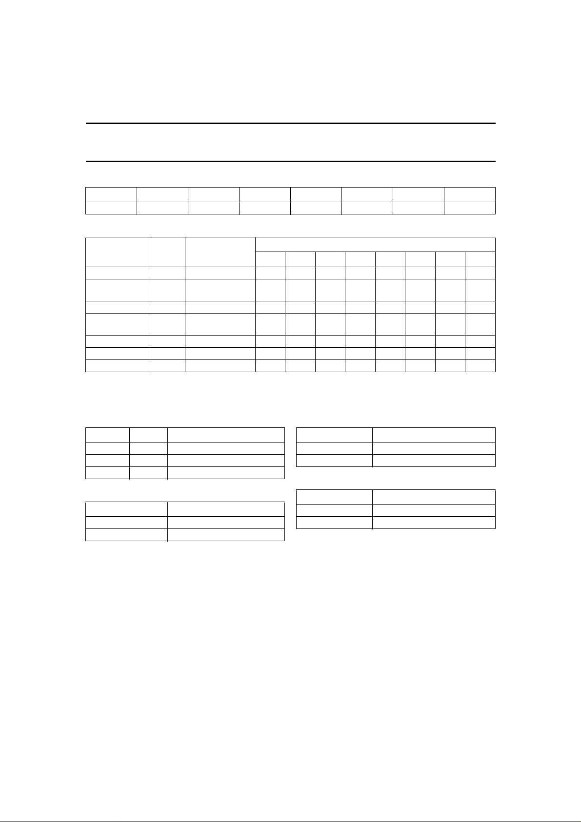
Table 1 Slave address.
A6 A5 A4 A3 A2 A1 A0 R/W
1 1 0 1 0 0 ADR X
Table 2 Control function.
CONTROL
FUNCTION
Control REG 00 X X X BON WD2 WD1 AMS SLP
User variable
gamma
Adaptive gamma DAC 02 X X D5 D4 D3 D2 D1 D0
Non-linear
amplifier
Line start stop REG 04 ST3 ST2 ST1 ST0 SP3 SP2 SP1 SP0
Field start stop REG 05 ST3 ST2 ST1 ST0 SP3 SP2 SP1 SP0
Status REG − X X X X X X X POR
Note
1. Valid sub-addresses: 00 to 05 (HEX); auto-increment mode available for sub-addresses.
Table 3 Window select bits (WD1 and WD2).
WD1 WD2 FUNCTION
0 0 default window
0 1 window by sandcastle blanking
1 X user window
Table 4 Amplitude select bit (AMS).
LOGIC LEVEL FUNCTION
0 0.3 V luminance
1 1 V luminance
TYPE SUB-ADDRESS
DAC 01 X X D5 D4 D3 D2 D1 D0
DAC 03 X X D5 D4 D3 D2 D1 D0
(1)
D7 D6 D5 D4 D3 D2 D1 D0
Table 5 Sleep mode bit (SLP).
LOGIC LEVEL FUNCTION
Table 6 Black offset compensation enable bit (BON).
LOGIC LEVEL FUNCTION
DATA BYTE
0 sleep
1 I2C-bus control
0 disabled
1 enabled
TDA9170
October 1994 7
Page 7

Philips Semiconductors Preliminary specification
YUV picture improvement processor based
on histogram modification
TDA9170
Window formats
Table 7 Line frequency start stop format.
LINE WINDOW
Start (LWS)
Stop (LWP)
(1)
4.5
⁄
+1⁄
× DEC(ST3, ST2, ST1, ST0) µs
64fh
+2⁄
× DEC(SP3, SP2, SP1, SP0) µs
64fh
26.5
64fh
⁄
64fh
TIMING
(2)
UNIT
Default DEC(ST3, ST2, ST1, ST0) = 2
DEC(SP3, SP2, SP1, SP0) = 14
Notes
1. Start and stop events are relative to the leading edge of the BK/CLP pulse of the sandcastle.
2. fh is defined as the line frequency.
Table 8 Field frequency start stop format.
FIELD WINDOW
(1)
TIMING UNIT
Start (FWS) 10 + 6 × DEC(ST3, ST2, ST1, ST0) lines
Stop (FWP) 121 + 10 × DEC(SP3, SP2, SP1, SP0) lines
Default DEC(ST3, ST2, ST1, ST0) = 9
DEC(SP3, SP2, SP1, SP0) = 4
Note
1. The start event is relative to the trailing edge of the first BK/CLP pulse after a field pulse recognition. The stop event
is relative to the actual start event.
October 1994 8
Page 8
Philips Semiconductors Preliminary specification
YUV picture improvement processor based
on histogram modification
TDA9170
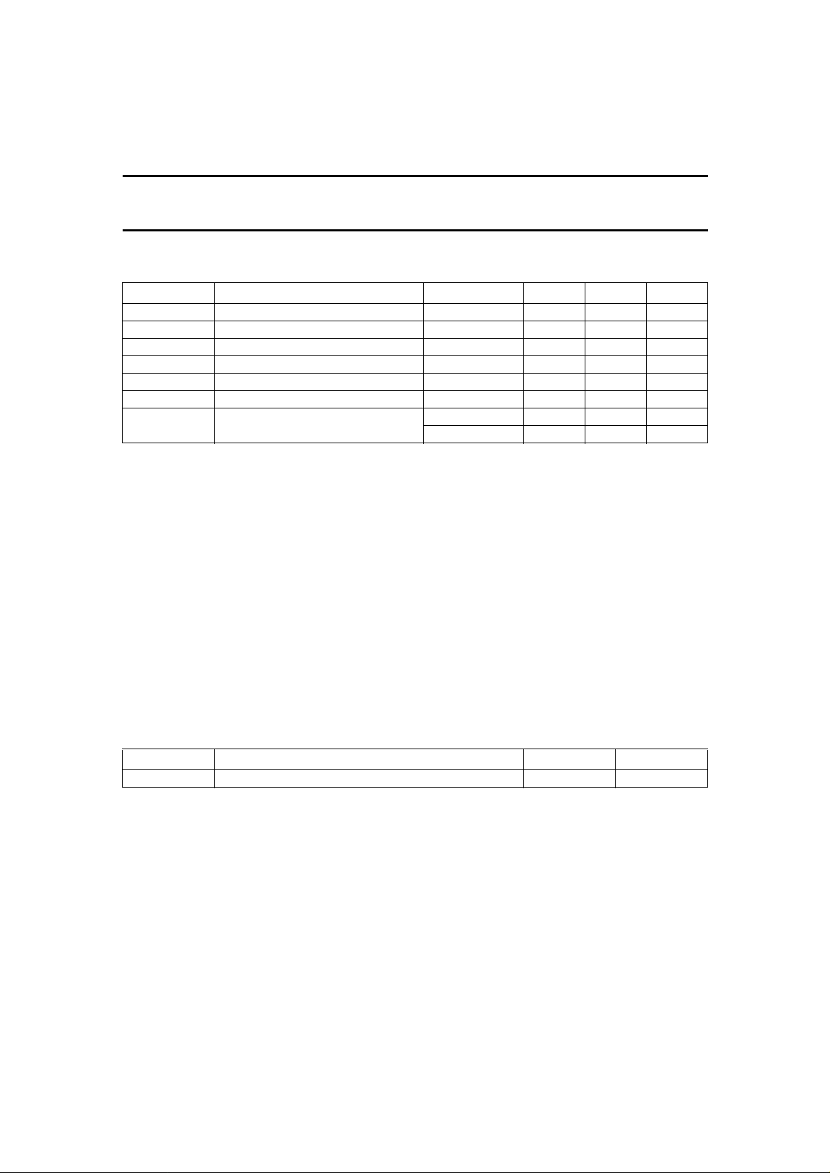
LIMITING VALUES
In accordance with the Absolute Maximum Rating System (IEC 134).
SYMBOL PARAMETER CONDITIONS MIN. MAX. UNIT
V
DDA
V
DDD
V
ref
V
n
T
stg
T
amb
V
es
analog supply voltage −0.5 +8.8 V
digital supply voltage −0.5 +5.5 V
reference supply voltage −0.5 +5.5 V
voltage input/output on any other pin −0.5 V
DDA
+ 0.5 V
storage temperature −55 +150 °C
operating ambient temperature −10 +70 °C
electrostatic discharge note 1 −2000 +2000 V
note 2 −200 +200 V
Notes
1. Human body model: equivalent to discharging a 100 pF capacitor through a 1.5 kΩ resistor.
2. Machine model: equivalent to discharging a 200 pF capacitor through a 0 Ω resistor.
QUALITY SPECIFICATION
In accordance with
Reference Handbook”
“SNW-FQ-611 part E”
. The numbers of the quality specification can be found in the
“Quality
. The Handbook can be ordered using the code 9398 510 63011. All pins are protected against
electrostatic discharge by means of clamping diodes.
Latch-up
At T
= 70 °C all pins meet the specification as follows, except for pins 6 and 7 at positive trigger currents:
amb
I
> 100 mA or V
trigger
I
< −100 mA or V
trigger
pin 6, V
pin 24, V
ref
: I
DDD
trigger
: I
trigger
> 1.5V
pin
< −0.5V
pin
> 40 mA or V
> 70 mA or V
DDA(max)
DDA(max)
> 1.5V
pin
pin
.
DDA(max)
> 1.5V
.
DDA(max)
.
.
THERMAL CHARACTERISTICS
SYMBOL PARAMETER VALUE UNIT
R
th j-a
thermal resistance from junction to ambient in free air 48 K/W
October 1994 9
Page 9

Philips Semiconductors Preliminary specification
YUV picture improvement processor based
on histogram modification
TDA9170
CHARACTERISTICS
V
DDA
= 8 V; T
= 25 °C; unless otherwise specified.
amb
SYMBOL PARAMETER CONDITIONS MIN. TYP. MAX. UNIT
Supply (pins 6, 9 and 24)
V
V
V
I
DDA
Z
Z
DDA
DDD
ref
o(24)
o(6)
analog supply voltage 7.2 − 8.8 V
digital supply voltage − 5.0 − V
reference supply voltage − 4.0 − V
analog supply current − 40 − mA
output impedance − − 250 Ω
output impedance − − 250 Ω
Luminance input/output selection
LUMINANCE INPUT (PIN 12); note 1
V
i(Y)
luminance input voltage AMPSEL= 0 0.3 − − V
AMPSEL = 1 1.0 − − V
V
i(Yclamp)
input voltage level during
− 1.5 − V
clamping
I
ib(Y)
input bias current − − 0.1 µA
LUMINANCE INPUT VOLTAGE RANGE SELECTION AMPSEL (PIN 13); note 2
V
i(SEL)l
input voltage selection for lower
− − 1.5 V
range
V
i(SEL)h
input voltage selection for
3.5 − − V
higher range
I
ib(SEL)
input bias current − − 0.1 µA
LUMINANCE OUTPUT (PIN 21)
V
o(Y)
luminance output voltage AMPSEL = 0 0.3 − − V
AMPSEL = 1 1.0 − − V
V
oYclamp
V
no
B
Y
B
Y(nl)
output voltage level during
clamping
output noise voltage 52 − − dB
luminance bandwidth transparent 7 9 − MHz
non-linear processing
AMPSEL = 0 − 2.9 − V
AMPSEL = 1 − 2.0 − V
10 − − MHz
luminance bandwidth
E
bl
E
G(n)
black level error no offset; transparent − − 1 %
nominal gain error no offset; transparent − − 8 %
Black detection and correction
BLACK DETECTOR
Bl
osd(max)
maximum black offset detection
23 25 27 %
at the input
Bl
osc(max)
maximum black offset correction
8 10 12 %
at the input
October 1994 10
Page 10

Philips Semiconductors Preliminary specification
YUV picture improvement processor based
on histogram modification
TDA9170
SYMBOL PARAMETER CONDITIONS MIN. TYP. MAX. UNIT
PICTURE AMPLITUDE STRETCH
E
G(s)
gain error after stretch maximum offset − − 1 %
BLACK OFFSET CORRECTION ON/OFF SWITCH BOF (PIN 11); note 2
V
i(blos)
input voltage level correction off − − 1.5 V
correction on 3.5 − − V
I
ib(blos)
input bias current − − 0.1 µA
TIME CONSTANT CONTROL TAUBP (PIN 4); see Fig.3
I
BP(d)
I
ibBP
V
BP(l)
V
BP(h)
discharge current − − 3.5 mA
input bias current − − 0.1 µA
control voltage lower limit − 1.0 − V
control voltage upper limit − 2.5 − V
TIME CONSTANT CONTROL TAUBL (PIN 5); see Fig.4
I
V
V
ibBL
BL(l)
BL(h)
input bias current − − 0.1 µA
control voltage lower limit − 2.0 − V
control voltage upper limit − 3.5 − V
Histogram measurement
HISTOGRAM UPDATES AT HMX (PINS 16 TO 20)
Q
HMb
V
HM(av)
segment bleeder accuracy − − 2 %
average voltage level for
− 1.0 − V
5 segments
V
HM(min)
V
HM(max)
I
ibHM
minimum segment voltage level 0 − − V
maximum segment voltage level − 5.0 − V
input bias current − − 0.1 µA
TIME CONSTANT CONTROL TAUHM (PIN 22); see Figs 5, 6 and 7
I
ibTHM
V
THM(l)
V
THM(h)
input bias current − − 0.1 µA
control voltage lower limit − 1.0 − V
control voltage upper limit − 2.0 − V
MISCOUNT DETECTION
Q
t
p(mc)
t
o(mc)
mc(d)
miscount detection level − 5 − %
miscount propagation delay 20% step − 25 − ns
miscount detection on-time for
0.31 0.36 0.41 µs
each event
t
Y(mc)
mismatch propagation and
− − 20 ns
luminance delay
Q
mc(aW)
miscount activation level at
no miscount − 90 − %
white
Q
mc(dW)
miscount de-activation level at
miscount − 87 − %
white
October 1994 11
Page 11

Philips Semiconductors Preliminary specification
YUV picture improvement processor based
on histogram modification
TDA9170
SYMBOL PARAMETER CONDITIONS MIN. TYP. MAX. UNIT
Processing of measured histogram values
ADAPTIVE GAMMA CONTROL RANGE
G
adg(min)
G
adg(max)
minimum gain for HM1 − 1 −
maximum gain for HM1 − 3 −
ADAPTIVE GAMMA SETTING ADGAM (PIN 4); note 3; see Fig.8
V
adg(l)
V
adg(h)
I
ibADG
G
adp(min)
G
adp(max)
control voltage lower limit − 1.75 − V
control voltage upper limit − 3.25 − V
input bias current − − 0.1 µA
minimum gain for HM1 no offset; G
maximum gain for HM1 no offset; G
= 1 − 1 −
VAR
= 1 − 3 −
VAR
ADAPTIVE GAMMA BY BLACK OFFSET
G
adb(min)
G
adb(max)
minimum gain for HM1 no offset; G
VAR
maximum gain for HM1 maximum offset;
G
= 1
VAR
= 1 − 1 −
− 2.5 −
WHITE-POINT STRETCH
G
wp
maximum gain luminance for
white stretch
HM-pattern = 01103:
Gnl= 1
− 1.09 −
Non-linear amplifier
N
ON-LINEAR GAIN SET BY HMX (PINS 16 TO 20)
Q
G
nl(b)
nl(min)
segment bleeder accuracy − − 2 %
minimum gain segment HM-pattern= 31100:
− 0.36 −
Gnl= 1
G
nl(max)
maximum gain segment HM-pattern = 31100:
− 2.28 −
Gnl= 1
NON-LINEARITY SETTING AMPNLA (PIN 3); note 3
V
V
I
ib(nl)
nl(l)
nl(h)
control voltage lower limit − 1.75 − V
control voltage upper limit − 3.25 − V
input bias current − − 0.1 µA
DYNAMICS
t
d(nl)
delay between linear and
− − 20 ns
non-linear path
Variable gamma
V
ARIABLE GAMMA CONTROL RANGE
G
VAR(min)
minimum variable gamma
− 0.5 −
setting
G
VAR(max)
maximum variable gamma
− 1.5 −
setting
October 1994 12
Page 12

Philips Semiconductors Preliminary specification
YUV picture improvement processor based
on histogram modification
TDA9170
SYMBOL PARAMETER CONDITIONS MIN. TYP. MAX. UNIT
VARIABLE GAMMA SETTING VARGAM(PIN 2);note3
V
VAR(l)
V
VAR(h)
V
VAR(lt)
I
ibVAR
control voltage lower limit − 1.75 − V
control voltage upper limit − 3.25 − V
control voltage for linear transfer − 2.5 − V
input bias current − − 0.1 µA
Colour difference processing
COLOUR DIFFERENCE INPUTS UIN AND VIN (PINS 5 AND 7)
V
V
I
ib
V
i(UIN)
i(VIN)
i(cl)
input voltage 1.8 − − V
input voltage 1.8 − − V
input bias current (pins 5 and 7) − − 0.1 µA
input voltage level during
− 1.5 − V
clamping
COLOUR DIFFERENCE OUTPUTS (PINS 28 AND 26)
∆V
o28
output voltage range with
150 − − %
respect to the input (pin 28)
∆V
o26
output voltage range with
150 − − %
respect to the input (pin 26)
V
o(cl)
output voltage level during
− 2.3 − V
clamping
E
off
E
G
offset error transparent − − 1 %
gain error transparent − − 5 %
B bandwidth transparent 20 30 − MHz
Timing
H
ORIZONTAL WINDOW GENERATION
fh line frequency 15 − 16 kHz
Default window setting (with respect to start BK/CLP pulse)
t
dh(ws)
t
dhd(wp)
default start window −
default window stop −
6.5
54.5
⁄
64fh
⁄
64fh
−
−
User window generation with I2C-bus (with respect to start BK/CLP pulse)
t
hws(min)
t
hws(max)
t
hwp(min)
t
hwp(max)
minimum start window −
maximum start window −
minimum window stop −
maximum window stop −
4.5
19.5
26.5
56.5
⁄
64fh
⁄
⁄
⁄
64fh
64fh
64fh
−
−
−
−
VERTICAL WINDOW GENERATION
fv vertical frequency 45 − 65 Hz
Default window setting (start event with respect to start detected field blanking, stop event with respect to start event)
t
dvws
t
dvdwp
default window start − 64 − lines
default window stop − 161 − lines
October 1994 13
Page 13
Philips Semiconductors Preliminary specification
YUV picture improvement processor based
on histogram modification
TDA9170
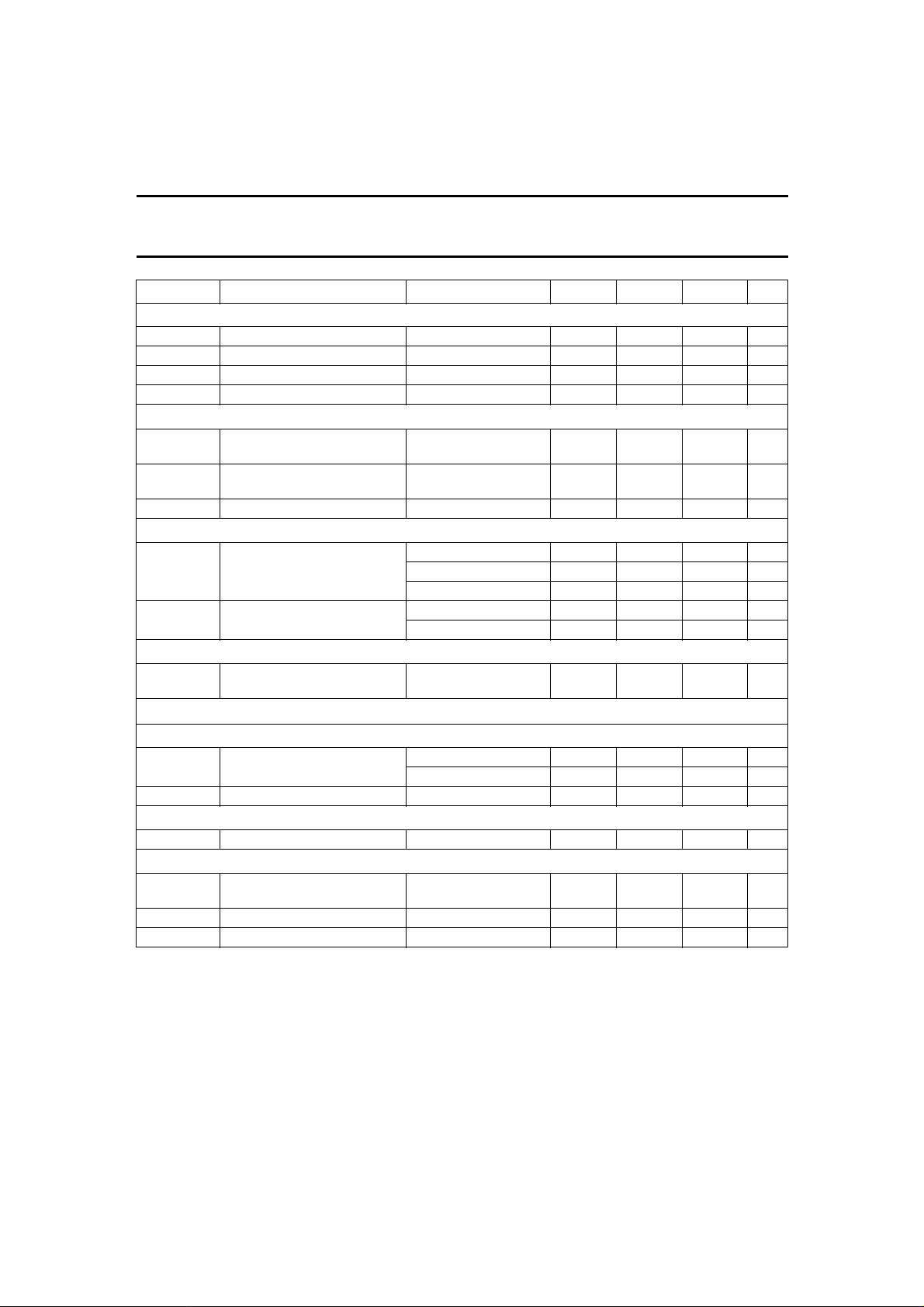
SYMBOL PARAMETER CONDITIONS MIN. TYP. MAX. UNIT
User window generation with I2C-bus
t
vsw(min)
t
vsw(max)
t
vwp(min)
t
vwp(max)
minimum window start − 10 − lines
maximum window start − 100 − lines
minimum window stop − 121 − lines
maximum window stop − 271 − lines
Default window select DWS; (pin 1): note 2
V
isc(DWS)
voltage input level for window
− − 1.5 V
by SC blanking
V
id(DWS)
voltage input level for default
3.5 − 5.5 V
window
I
ibDWS
input bias current V
DWS
= V
DDA
− − 10 µA
Sandcastle input SC; (pin 10)
V
i(SC)
voltage input level no blanking; no clamp − 0 1.0 V
with blanking; no clamp 1.2 1.5 1.8 V
with blanking and clamp 3.1 3.5 3.9 V
t
i(sw)
input sync width no vertical sync − − 15 µs
with vertical sync 35 − − µs
CLP PULSE WIDTH RESTORATION
t
d(clp)
internal CLP pulse width
− −100 − ns
difference
2
I
C-bus specification
ADDRESS SELECT ADR (PIN 32)
V
iADR
input voltage level A0 = 0 − − 1.5 V
A1 = 1 3.5 − 5.5 V
I
ibADR
input bias current − − 0.1 µA
TEST PINS TM AND DT (PINS 29 AND 27)
V
i(test)
input voltage level − − 0.5 V
Overall output performance
t
d(YUV)
delay from input to output of
transparent − 50 100 ns
YUV
t
dm(YUV)
α
w(YUV)
delay of matching YUV transparent − 10 20 ns
crosstalk from window any channel − − −60 dB
Notes
1. Input amplitude values greater than the minimum specified range are still processed. However, the gain will slowly
saturate. Amplitudes up to +4 dB are permitted without significant clipping.
2. This select is valid provided the sleep mode bit is not set.
3. This control is valid provided the sleep mode bit is not set.
October 1994 14
Page 14
Philips Semiconductors Preliminary specification
BBBBBBBBBBBBBBBBBBBBB
BBBBBBBBBBBBBBBBBBBBB
BBBBBBBBBBBBBBBBBBBBB
BBBBBBBBBBBBBBBBBBBBB
BBBBBBBBBBBBBBBBBBBBB
BBBBBBBBBBBBBBBBBBBBB
BBBBBBBBBBBBBBBBBBBBB
BBBBBBBBBBBBBBBBBBBBB
BBBBBBBBBBBBBBBBBBBBB
BBBBBBBBBBBBBBBBBBBBB
BBBBBBBBBBBBBBBBBBBBB
BBBBBBBBBBBBBBBBBBBBB
BBBBBBBBBBBBBBBBBBBBB
BBBBBBBBBBBBBBBBBBBBB
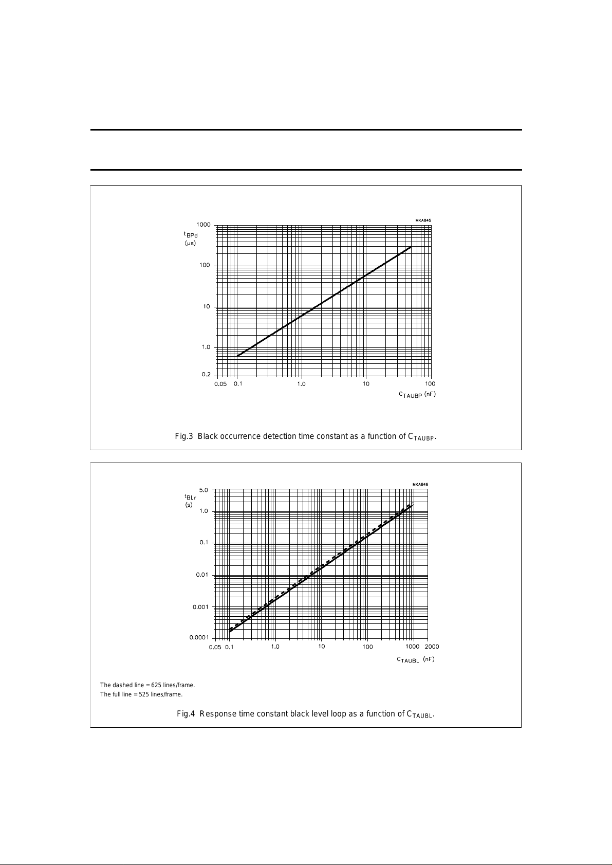
Fig.3 Black occurrence detection time constant as a function of C
TAUBP
.
BBBBBBBBBBBBBBBBBBBB
BBBBBBBBBBBBBBBBBBBB
BBBBBBBBBBBBBBBBBBBB
BBBBBBBBBBBBBBBBBBBB
BBBBBBBBBBBBBBBBBBBB
BBBBBBBBBBBBBBBBBBBB
BBBBBBBBBBBBBBBBBBBB
BBBBBBBBBBBBBBBBBBBB
BBBBBBBBBBBBBBBBBBBB
BBBBBBBBBBBBBBBBBBBB
BBBBBBBBBBBBBBBBBBBB
BBBBBBBBBBBBBBBBBBBB
BBBBBBBBBBBBBBBBBBBB
BBBBBBBBBBBBBBBBBBBB
BBBBBBBBBBBBBBBBBBBB
Fig.4 Response time constant black level loop as a function of C
TAUBL
.
The dashed line =625 lines/frame.
The full line =525 lines/frame.
YUV picture improvement processor based
on histogram modification
TDA9170
October 1994 15
Page 15
Philips Semiconductors Preliminary specification
BBBBBBBBBBBBBBBBBBBB
BBBBBBBBBBBBBBBBBBBB
BBBBBBBBBBBBBBBBBBBB
BBBBBBBBBBBBBBBBBBBB
BBBBBBBBBBBBBBBBBBBB
BBBBBBBBBBBBBBBBBBBB
BBBBBBBBBBBBBBBBBBBB
BBBBBBBBBBBBBBBBBBBB
BBBBBBBBBBBBBBBBBBBB
BBBBBBBBBBBBBBBBBBBB
BBBBBBBBBBBBBBBBBBBB
BBBBBBBBBBBBBBBBBBBB
BBBBBBBBBBBBBBBBBBBB
BBBBBBBBBBBBBBBBBBBB
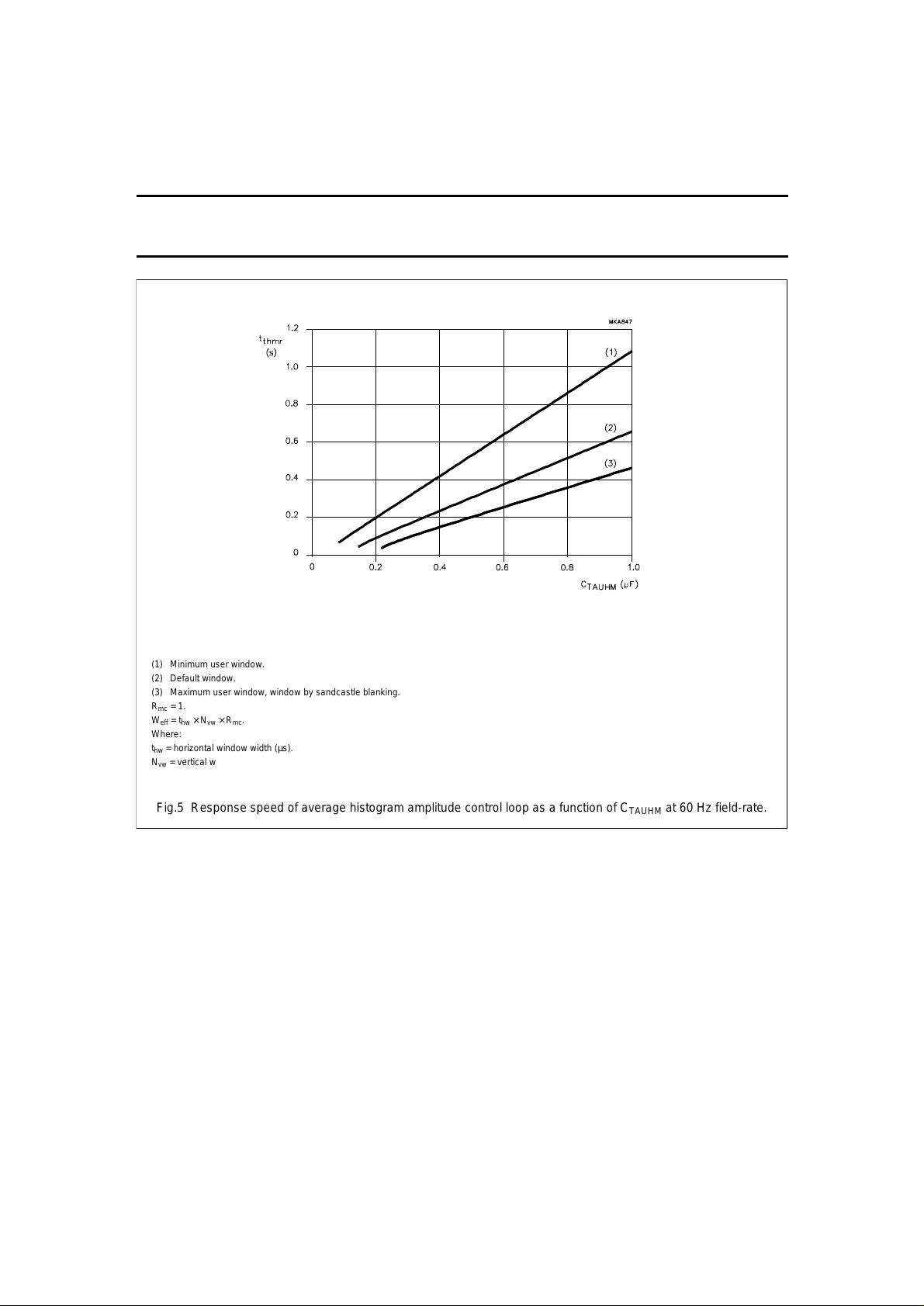
Fig.5 Response speed of average histogram amplitude control loop as a function of C
TAUHM
at 60 Hz field-rate.
(1) Minimum user window.
(2) Default window.
(3) Maximum user window, window by sandcastle blanking.
Rmc= 1.
W
eff
= thw× Nvw× Rmc.
Where:
thw= horizontal window width (µs).
Nvw= vertical window height (lines).
Rmc= effective histogram measuring time within window due to miscount in percentage of thw× Nvw.
YUV picture improvement processor based
on histogram modification
TDA9170
October 1994 16
Page 16
Philips Semiconductors Preliminary specification
BBBBBBBBBBBBBBBBBBBB
BBBBBBBBBBBBBBBBBBBB
BBBBBBBBBBBBBBBBBBBB
BBBBBBBBBBBBBBBBBBBB
BBBBBBBBBBBBBBBBBBBB
BBBBBBBBBBBBBBBBBBBB
BBBBBBBBBBBBBBBBBBBB
BBBBBBBBBBBBBBBBBBBB
BBBBBBBBBBBBBBBBBBBB
BBBBBBBBBBBBBBBBBBBB
BBBBBBBBBBBBBBBBBBBB
BBBBBBBBBBBBBBBBBBBB
BBBBBBBBBBBBBBBBBBBB
BBBBBBBBBBBBBBBBBBBB
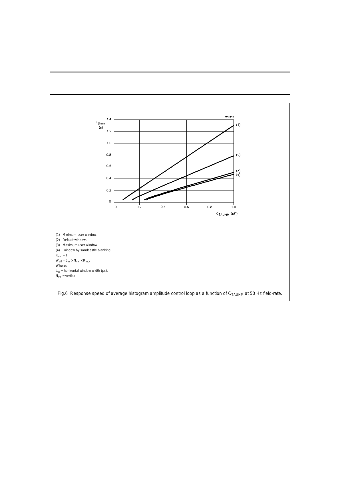
Fig.6 Response speed of average histogram amplitude control loop as a function of C
TAUHM
at 50 Hz field-rate.
(1) Minimum user window.
(2) Default window.
(3) Maximum user window.
(4) window by sandcastle blanking.
Rmc= 1.
W
eff
= thw× Nvw× Rmc.
Where:
thw= horizontal window width (µs).
Nvw= vertical window height (lines).
Rmc= effective histogram measuring time within window due to miscount in percentage of thw× Nvw.
YUV picture improvement processor based
on histogram modification
TDA9170
October 1994 17
Page 17
Philips Semiconductors Preliminary specification
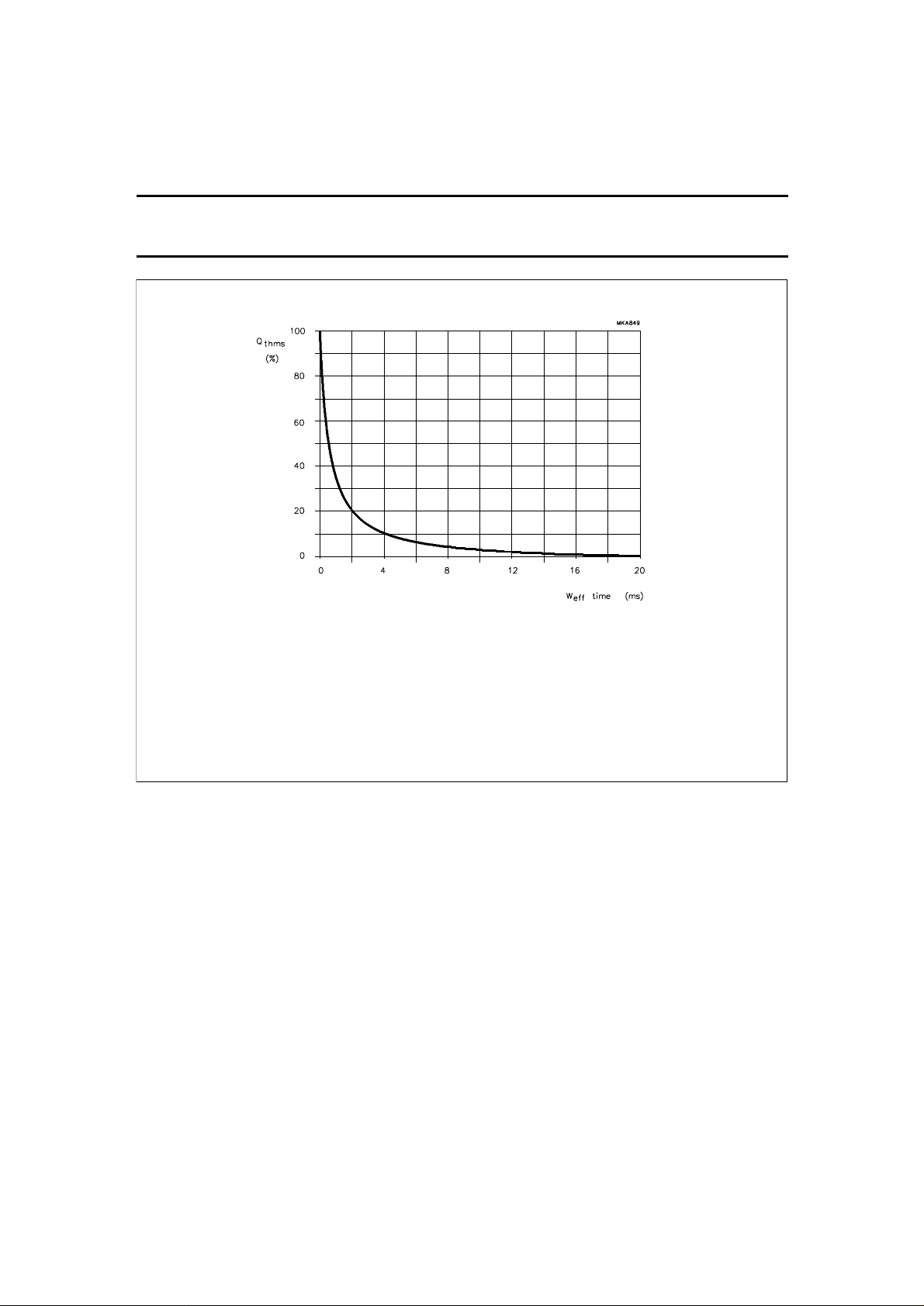
Fig.7 Static error on average histogram amplitude (pin TAUHM) as a function of effective histogram measuring
time in a field.
W
eff
= thw× Nvw× Rmc.
Where:
thw= horizontal window width (µs).
Nvw= vertical window height (lines).
Rmc= effective histogram measuring time within window due to miscount in
percentage of t
hw
× Nvw.
YUV picture improvement processor based
on histogram modification
TDA9170
October 1994 18
Page 18
Philips Semiconductors Preliminary specification
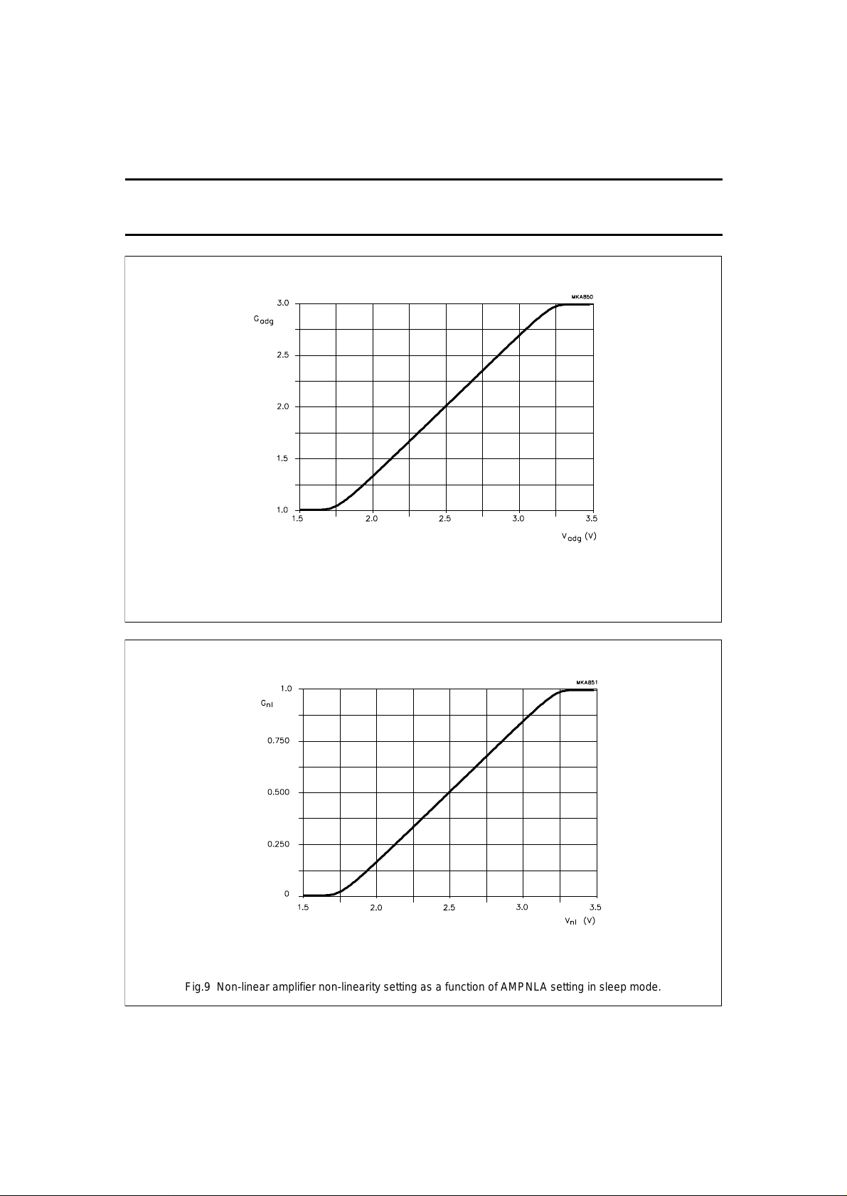
Fig.8 Adaptive gamma gain setting as a function of ADGAM setting in sleep mode.
BBBBBBBBBBBBBBBBBBBB
BBBBBBBBBBBBBBBBBBBB
BBBBBBBBBBBBBBBBBBBB
BBBBBBBBBBBBBBBBBBBB
BBBBBBBBBBBBBBBBBBBB
BBBBBBBBBBBBBBBBBBBB
BBBBBBBBBBBBBBBBBBBB
BBBBBBBBBBBBBBBBBBBB
BBBBBBBBBBBBBBBBBBBB
BBBBBBBBBBBBBBBBBBBB
BBBBBBBBBBBBBBBBBBBB
BBBBBBBBBBBBBBBBBBBB
BBBBBBBBBBBBBBBBBBBB
BBBBBBBBBBBBBBBBBBBB
BBBBBBBBBBBBBBBBBBBBB
BBBBBBBBBBBBBBBBBBBBB
BBBBBBBBBBBBBBBBBBBBB
BBBBBBBBBBBBBBBBBBBBB
BBBBBBBBBBBBBBBBBBBBB
BBBBBBBBBBBBBBBBBBBBB
BBBBBBBBBBBBBBBBBBBBB
BBBBBBBBBBBBBBBBBBBBB
BBBBBBBBBBBBBBBBBBBBB
BBBBBBBBBBBBBBBBBBBBB
BBBBBBBBBBBBBBBBBBBBB
BBBBBBBBBBBBBBBBBBBBB
BBBBBBBBBBBBBBBBBBBBB
BBBBBBBBBBBBBBBBBBBBB
BBBBBBBBBBBBBBBBBBBBB
Fig.9 Non-linear amplifier non-linearity setting as a function of AMPNLA setting in sleep mode.
YUV picture improvement processor based
on histogram modification
TDA9170
October 1994 19
Page 19
Philips Semiconductors Preliminary specification
BBBBBBBBBBBBBBBBBBBB
BBBBBBBBBBBBBBBBBBBB
BBBBBBBBBBBBBBBBBBBB
BBBBBBBBBBBBBBBBBBBB
BBBBBBBBBBBBBBBBBBBB
BBBBBBBBBBBBBBBBBBBB
BBBBBBBBBBBBBBBBBBBB
BBBBBBBBBBBBBBBBBBBB
BBBBBBBBBBBBBBBBBBBB
BBBBBBBBBBBBBBBBBBBB
BBBBBBBBBBBBBBBBBBBB
BBBBBBBBBBBBBBBBBBBB
BBBBBBBBBBBBBBBBBBBB
BBBBBBBBBBBBBBBBBBBB
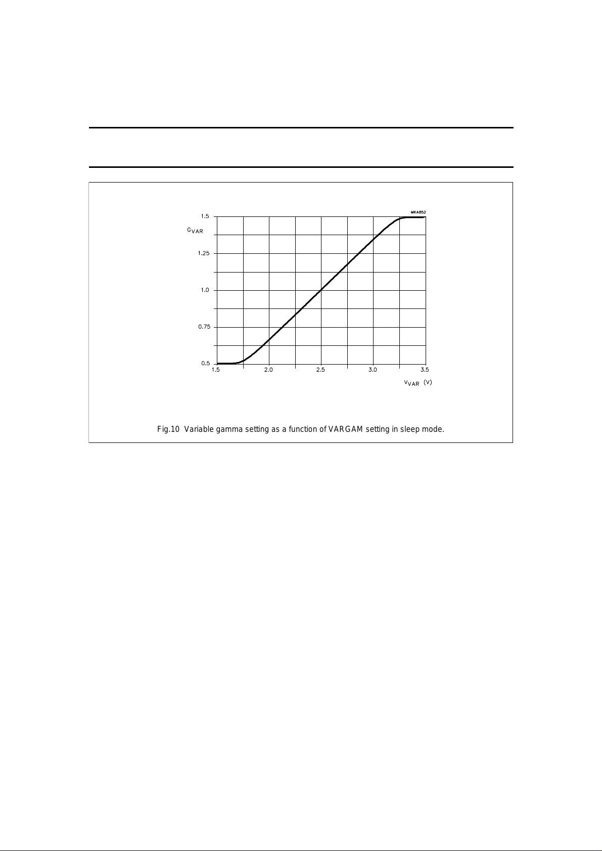
Fig.10 Variable gamma setting as a function of VARGAM setting in sleep mode.
YUV picture improvement processor based
on histogram modification
TDA9170
October 1994 20
Page 20
Philips Semiconductors Preliminary specification
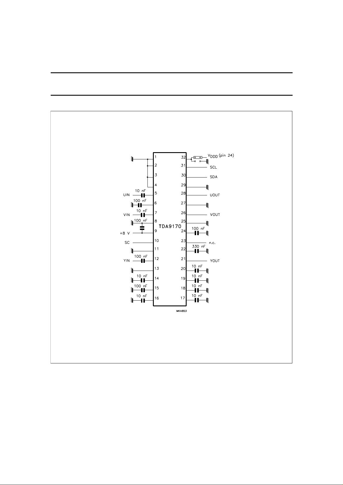
Fig.11 Application diagram.
YUV picture improvement processor based
on histogram modification
APPLICATION INFORMATION (BUS-MODE)
TDA9170
October 1994 21
Page 21
Philips Semiconductors Preliminary specification
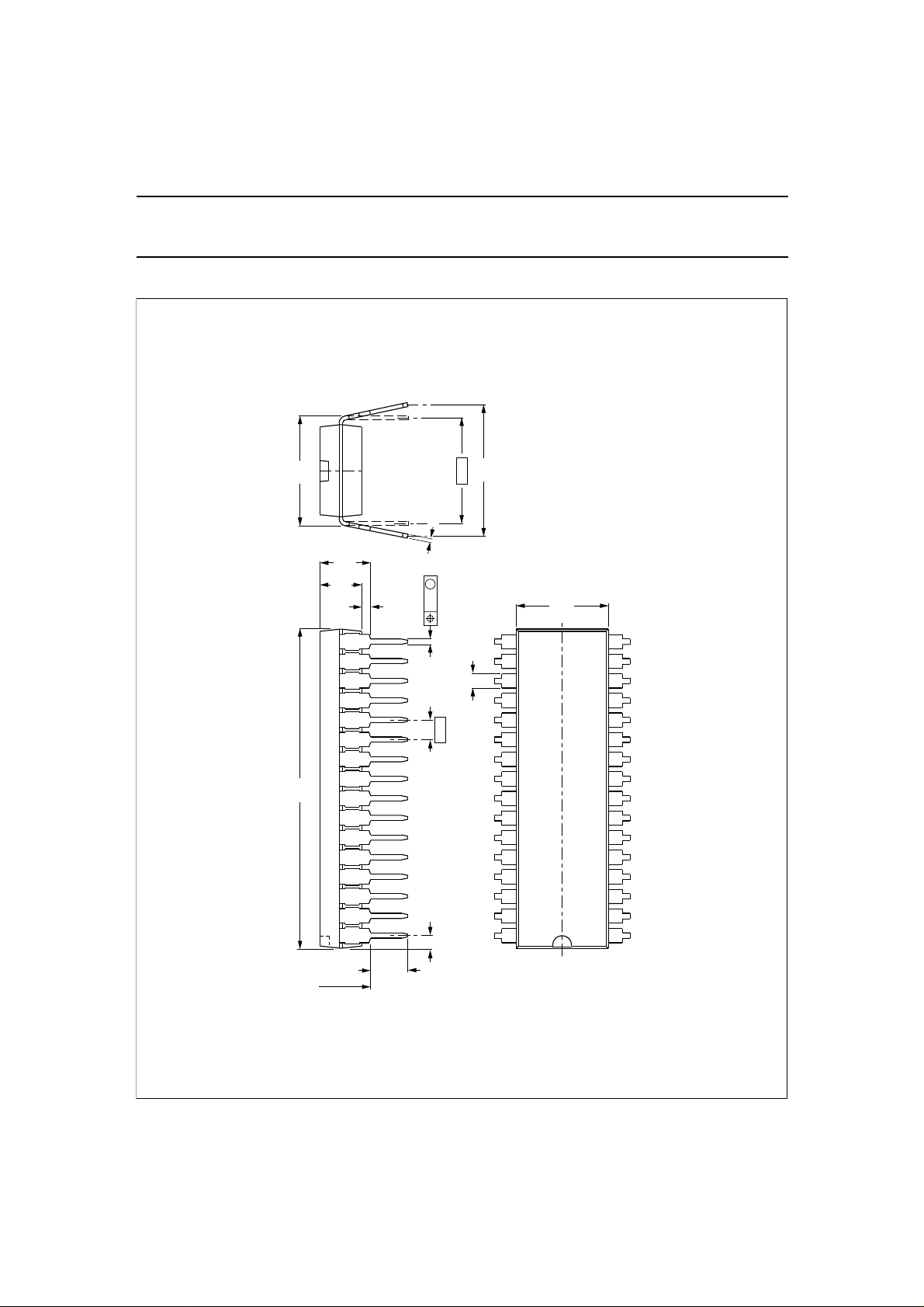
Fig.12 Plastic shrink dual in-line package; 32 leads (400 mil) SDIP32; SOT232-1.
17
16
1.3 max
9.1
8.7
29.4
28.5
3.8
max
4.7
max
0.51
min
0.18
M
0.53
max
1.778
(15x)
3.2
2.8
seating plane
1.6
max
10.7
10.2
0.32 max
10.16
12.2
10.5
MSA270
32
1
Dimensions in mm.
YUV picture improvement processor based
on histogram modification
PACKAGE OUTLINE
TDA9170
October 1994 22
Page 22
Philips Semiconductors Preliminary specification
YUV picture improvement processor based
on histogram modification
SOLDERING
Plastic dual in-line packages
B
Y DIP OR WAVE
The maximum permissible temperature of the solder is
260 °C; this temperature must not be in contact with the
joint for more than 5 s. The total contact time of successive
solder waves must not exceed 5 s.
The device may be mounted up to the seating plane, but
the temperature of the plastic body must not exceed the
specified storage maximum.
DEFINITIONS
Data sheet status
Objective specification This data sheet contains target or goal specifications for product development.
Preliminary specification This data sheet contains preliminary data; supplementary data may be published later.
Product specification This data sheet contains final product specifications.
Limiting values
Limiting values given are in accordance with the Absolute Maximum Rating System (IEC 134). Stress above one or
more of the limiting values may cause permanent damage to the device. These are stress ratings only and operation
of the device at these or at any other conditions above those given in the Characteristics sections of the specification
is not implied. Exposure to limiting values for extended periods may affect device reliability.
Application information
Where application information is given, it is advisory and does not form part of the specification.
If the printed-circuit board has been pre-heated, forced
cooling may be necessary immediately after soldering to
keep the temperature within the permissible limit.
EPAIRING SOLDERED JOINTS
R
Apply a low voltage soldering iron below the seating plane
(or not more than 2 mm above it). If its temperature is
below 300 °C, it must not be in contact for more than 10 s;
if between 300 and 400 °C, for not more than 5 s.
TDA9170
LIFE SUPPORT APPLICATIONS
These products are not designed for use in life support appliances, devices, or systems where malfunction of these
products can reasonably be expected to result in personal injury. Philips customers using or selling these products for
use in such applications do so at their own risk and agree to fully indemnify Philips for any damages resulting from such
improper use or sale.
PURCHASE OF PHILIPS I
October 1994 23
2
C COMPONENTS
Purchase of Philips I
components in the I2C system provided the system conforms to the I2C specification defined by
Philips. This specification can be ordered using the code 9398 393 40011.
2
C components conveys a license under the Philips’ I2C patent to use the
 Loading...