

Page 1

INTEGRATED CIRCUITS
DATA SH EET
TDA8442
2
I
C-bus interface for colour
decoders
Product specification
File under Integrated Circuits, IC01
March 1991
Page 2
Philips Semiconductors Product specification
I2C-bus interface for colour decoders
GENERAL DESCRIPTION
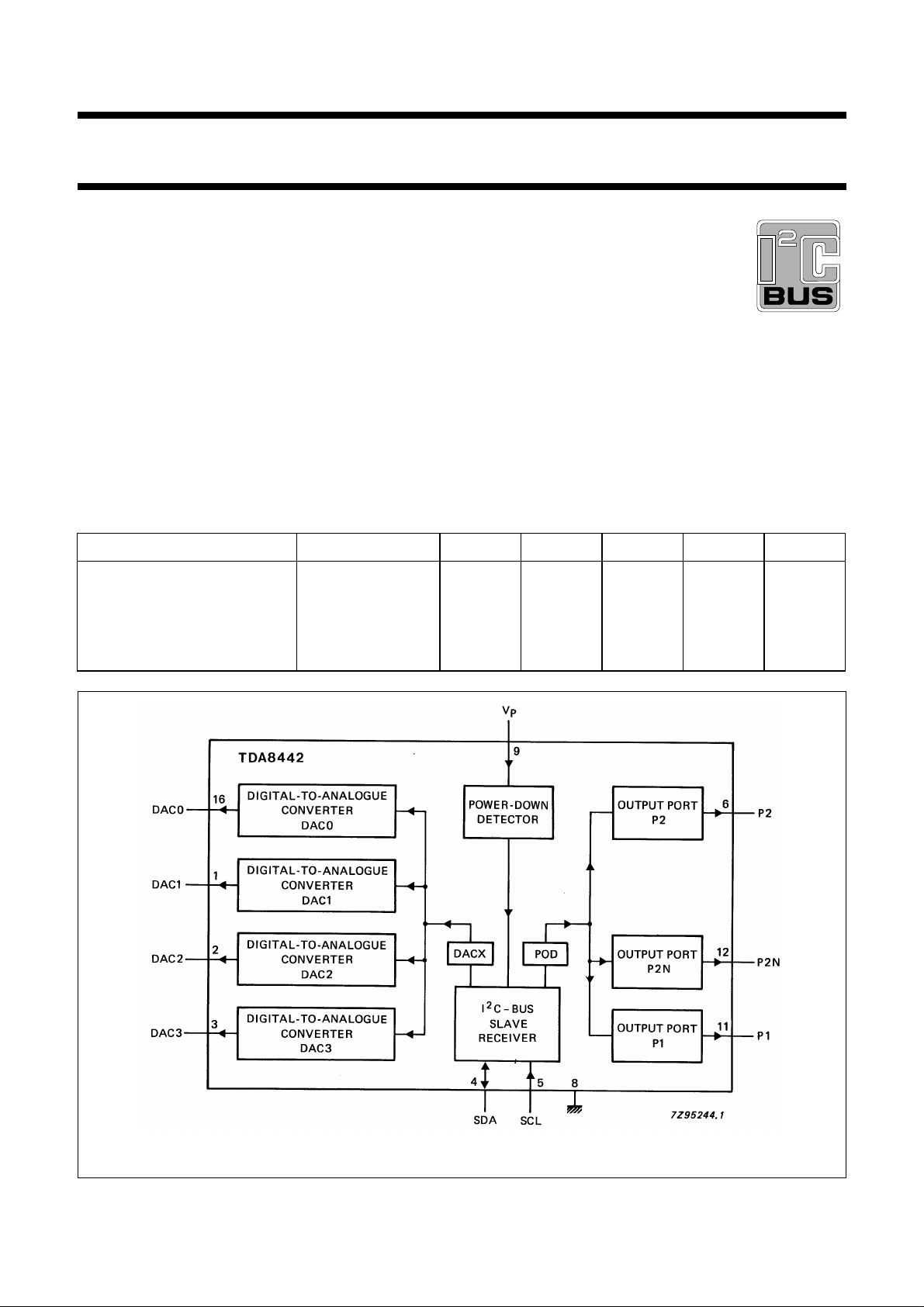
The TDA8442 provides control of four analogue functions
and has one high-current and two switching outputs.
Control of the IC is performed via the two-line, bidirectional
I2C-bus.
Features
• Four analogue control outputs
• One high-current output port (npn open emitter)
• Two switching output ports (npn collector with internal
pull-up resistor)
2
• I
C-bus slave receiver
• Power-down reset.
QUICK REFERENCE DATA
PARAMETER CONDITIONS SYMBOL MIN. TYP. MAX UNIT
Supply voltage (pin 9) V
Supply current no outputs loaded I
Total power dissipation no outputs loaded P
Operating ambient
temperature range
TDA8442
PACKAGE OUTLINE
16-lead DIL; plastic (SOT38); SOT38-1; 1996 July 23.
10.8 12.0 13.2 V
8 1318mA
−−1W
−20 −+70 °C
T
P
P
tot
amb
Fig.1 Block diagram.
March 1991 2
Page 3
Philips Semiconductors Product specification
I2C-bus interface for colour decoders
PINNING
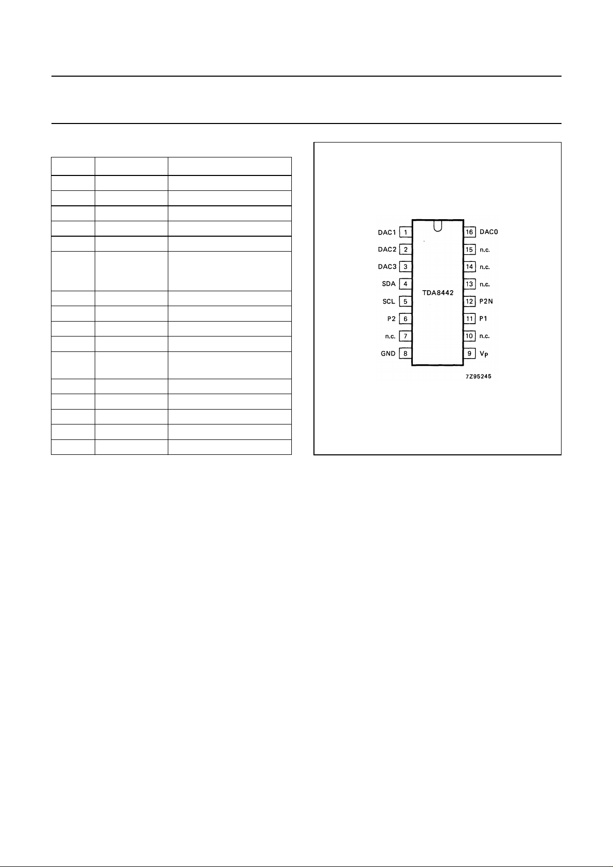
PIN SYMBOL DESCRIPTION
1 DAC1 analogue output 1
2 DAC2 analogue output 2
3 DAC3 analogue output 3
4 SDA serial data line; I
5 SCL serial clock line; I
6 P2 Port 2 npn collector output
with internal pull-up
resistor
7 n.c. not connected
8 GND supply return (ground)
9V
10 n.c. not connected
11 P1 Port 1 open npn emitter
12 P2N inverted P2 output
13 n.c. not connected
14 n.c. not connected
15 n.c. not connected
16 DAC0 analogue output 0
P
positive supply voltage
output
2
C-bus
2
C-bus
TDA8442
Fig.2 Pinning diagram
FUNCTIONAL DESCRIPTION
Control
Analogue control is facilitated by four 6-bit digital-to-analogue converters (DAC0 to DAC3).
The values of the output voltages from the DACs are set via the I
The high-current output port (P1) is suitable for switching between internal and external RGB signals.
It is an open npn emitter output capable of sourcing 14 mA (min.).
The two output ports (P2 and P2N) can be used for NTSC/PAL switching. These are npn collector outputs with internal
pull-up resistors of 10 kΩ (typ.). Both outputs are capable of sinking up to 2 mA with a voltage drop of less than 400 mV.
If one output is switched on (LOW), the other output is switched off, and vice versa.
Reset
The power-down-reset mode occurs whenever the positive supply voltage falls below 8.5 V (typ.) and resets all registers
to a defined state.
2
C-bus.
March 1991 3
Page 4
Philips Semiconductors Product specification
I2C-bus interface for colour decoders
OPERATION
Write
2
The TDA8442 is controlled via the I
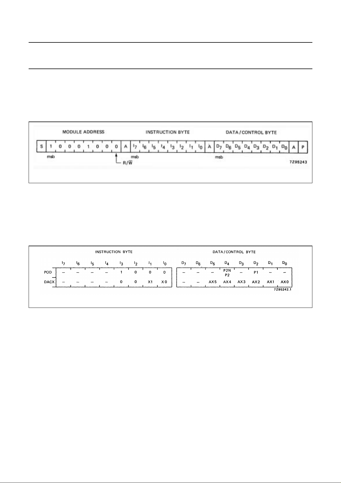
Programming of the TDA8442 is performed using the format shown in Fig.3.
Acknowledge (A) is generated by the TDA8442 only when a valid address is received and the device is not in the
power-down-reset mode (V
Control
> 8.5 V (typ.)).
P
C-bus (specifications for the I2C-bus will be supplied on request).
Fig.3 TDA8442 programming format.
TDA8442
Control is implemented by the instruction bytes POD (port output data) and DACX (digital-to-analogue converter control)
together with the corresponding data/control bytes (see Fig.4).
Fig.4 Control porgramming.
POD bit P1
If a logic 1 is programmed, the P1 output is switched on. If a logic 0 is programmed or after a power-down-reset, the P1
output is switched off (high-impedance state).
POD bit P2/P2N
If a logic 1 is programmed, the P2 output is switched off and the P2N output is switched on (LOW). If a logic 0 is
programmed or after a power-down-reset, the P2 output is switched on (LOW) and the P2N output is switched off.
DAX bits AX5 to AX0
The digital-to-analogue converter selected corresponds to the decimal equivalent of the two bits X1 and X0. The output
voltage of the selected DAC is programmed using bits AX5 to AX0, the lowest value being with all data AX5 to AX0 at
logic 0 or when power-down-reset has been activated.
March 1991 4
Page 5
Philips Semiconductors Product specification
I2C-bus interface for colour decoders
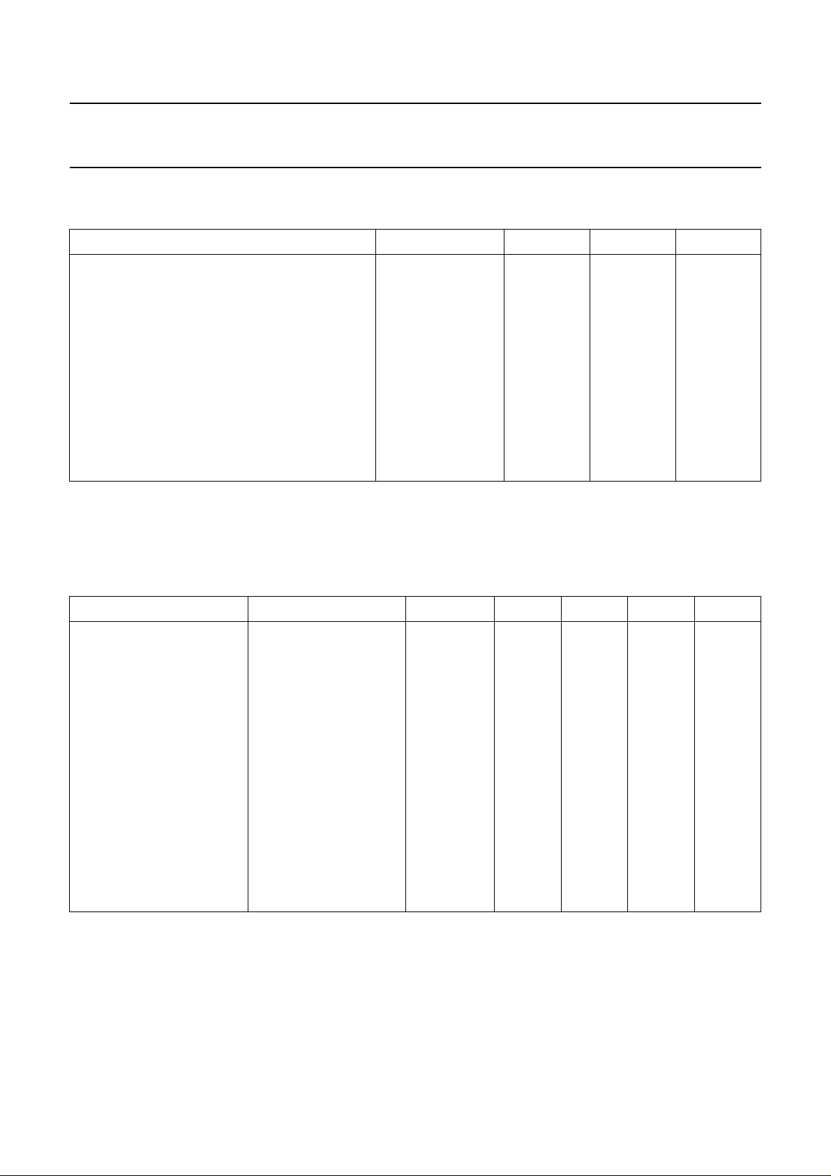
RATINGS
Limiting values in accordance with the Absolute Maximum System (IEC 134)
PARAMETER SYMBOL MIN. MAX. UNIT
Supply voltage range (pin 9) V
Input/output voltage ranges
pin 4 V
pin 5 V
pin 6 V
pin 11 V
pin 12 V
pin 1 to 3 and pin 16 V
Total power dissipation P
Operating ambient temperature range T
Storage temperature range T
Note
1. Pin voltage may exceed V
if the current in that pin is limited to 10 mA.
P
P
SDA
SCL
P2
P1
P2N
DAX
tot
amb
stg
TDA8442
−0.3 +13.2 V
−0.3 +13.2 V
−0.3 +13.2 V
−0.3 VP; note 1 V
−0.3 VP; note 1 V
−0.3 VP; note 1 V
−0.3 VP; note 1 V
− 1W
−20 +70 °C
−55 +150 °C
CHARACTERISTICS
= 12 V; T
V
P
= +25 °C; unless otherwise specified
amb
PARAMETER CONDITIONS SYMBOL MIN. TYP. MAX. UNIT
Supplies
Supply voltage (pin 9) V
Supply current (pin 9) no outputs loaded I
2
I
C-bus inputs
SDA (pin 4); SCL (pin 5)
Input voltage HIGH note 1 V
Input voltage LOW V
Input current HIGH note 1 I
Input current LOW note 1 I
2
I
C-bus output
SDA (pin 4) open collector
Output voltage LOW IOL = 3.0 mA V
Maximum output sink current I
P
IH
IL
OL
P
IH
IL
OL
10.8 12.0 13.2 V
8 1318mA
3.0 − VP− 1V
−0.3 − 1.5 V
−−10 µA
−−10 µA
−−0.4 V
35−mA
March 1991 5
Page 6
Philips Semiconductors Product specification
I2C-bus interface for colour decoders
P ARAMETER CONDITIONS SYMBOL MIN. TYP. MAX. UNIT
Ports P2 and P2N
(pins 6 and 12) npn collector output with
pull-up resistor to V
Internal pull-up resistor to V
Output voltage switched
P
I
= 2 mA V
OL
on (LOW)
Maximum output sink current I
Leakage current output
switched off
Port P1 (pin 11)
Output current switched on V
Leakage current switched off V
Digital-to-analogue
open npn emitter output
= 0 to 5 V I
O
= 0 to V
O
P
note 2
outputs
DAC0 (pin 16)
Maximum output voltage unloaded; note 3 V
Minimum output voltage unloaded; note 3 V
Positive value of smalles
I
= 2 mA (1 lsb); note 3 V
O
step
Deviation from linearity I
Output impedance I
= 2 mA ∆V −−45 mV
O
= −2 to +2 mA Z
O
Maximum output source
current
Maximum output sink current I
DAC1 (pin 1)
Maximum output voltage unloaded; note 3 V
Minimum output voltage unloaded; note 3 V
Positive value of smallest
I
= 2 mA (1 lsb); note 3 V
O
step
Deviation from linearity I
Output impedance I
= 2 mA ∆V −−50 mV
O
= −2 to +2 mA Z
O
Maximum output source
current
Maximum output sink current I
P
R
O
OL
OL
− I
O
± I
O max
O min
O lsb
O
−I
OH
OL
O max
O min
O lsb
O
−I
OH
OL
leak
leak
TDA8442
5 1015kΩ
−−0.4 V
25−mA
−−25 µA
14 −−mA
−−100 µA
3.0 − 4.25 V
0.15 − 1.0 V
16 − 72 mV
−−30 Ω
2 − 6mA
28−mA
4.0 − 5.0 V
1.0 − 1.7 V
18 − 86 mV
−−30 Ω
2 − 6mA
28−mA
March 1991 6
Page 7

Philips Semiconductors Product specification
I2C-bus interface for colour decoders
PARAMETER CONDITIONS SYMBOL MIN. TYP. MAX. UNIT
DAC2 (pin 2)
Maximum output voltage unloaded; note 3 V
Minimum output voltage unloaded; note 3 V
Positive value of smallest
step
Deviation from linearity I
Output impedance I
Maximum output source
current
Maximum output sink current I
DAC3 (pin 3)
Maximum output voltage unloaded; note 3 V
Minimum output voltage unloaded; note 3 V
Positive value of smallest
step
Deviation from linearity I
Output impedance I
Maximum output source
current
Maximum output sink current I
Power-down reset
Maximum value of VP at
which power-down reset is
active
Rise time of V
during
P
power-on
I
= 2 mA (1 lsb); note 3 V
O
= 2 mA ∆V −−50 mV
O
= −2 to +2 mA Z
O
I
= 2 mA (1 lsb); note 3 V
O
= 2 mA ∆V −−150 mV
O
= −2 to +2 mA Z
O
VP rising from 0 V to VPDt
O max
O min
O lsb
O
−I
OH
OL
O max
O min
O lsb
O
−I
OH
OL
V
PD
r
TDA8442
4.0 − 5.0 V
1.0 − 1.7 V
18 − 86 mV
−−30 Ω
2 − 6mA
28−mA
10.0 − 11.2 V
0.1 − 1.0 V
70 − 250 mV
−−30 Ω
2 − 6mA
28−mA
6 − 10 V
5 −−µs
Notes to the Characteristics
1. If VP < 1 V, the input current is limited to 10 µA at input voltages up to 13.2 V.
2. Pure capacitive load should be avoided because of possible oscillations.
3. Values are proportional to VP.
March 1991 7
Page 8
Philips Semiconductors Product specification
I2C-bus interface for colour decoders
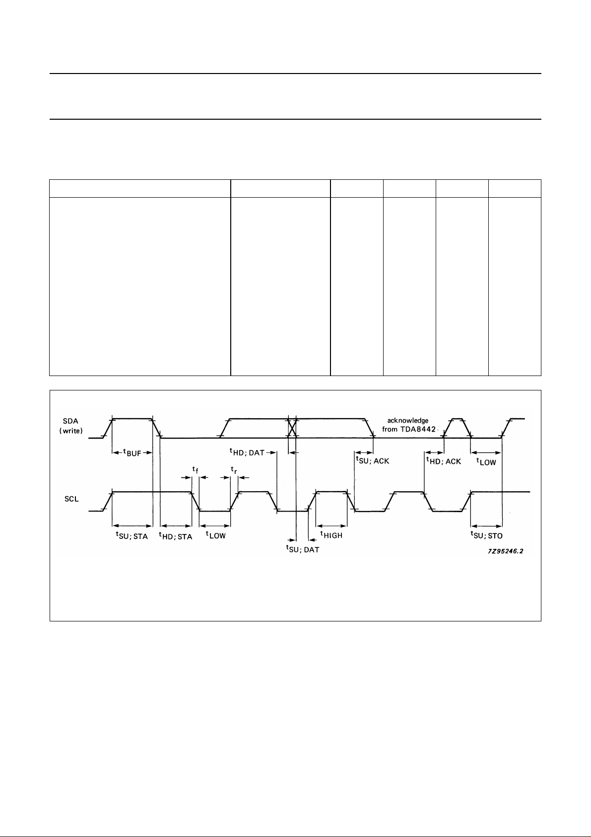
I2C-BUS TIMING
Bus loading conditions: 4kΩ pull-up resistor to +5 V; 200 pF capacitor to GND.
All values are referred to V
PARAMETER SYMBOL MIN. TYP. MAX. UNIT
Bus free before start t
Start condition set-up time t
Start condition hold time t
LOW period SCL, SDA t
HIGH period SCL t
Rise time SCL, SDA t
Fall time SCL, SDA t
Data set-up time (write) t
Data hold time (write) t
Acknowledge (from TDA8442) set-up time t
Acknowledge (from TDA8442) hold time t
Stop condition set-up time t
= 3 V and VIL = 1.5 V.
IH
BUF
SU; STA
HD; STA
LOW
HIGH
r
f
SU; DAT
HD; DAT
SU; ACK
HD; ACK
SU; STO
4.0 −−µs
4.0 −−µs
4.0 −−µs
4.0 −−µs
4.0 −−µs
−−1.0 µs
−−0.30 µs
1 −−µs
1 −−µs
−−3.5 µs
0 −−µs
4.0 −−µs
TDA8442
Reference levels are 10 and 90%.
Fig.5 I2C-bus timing; TDA8442.
March 1991 8
Page 9
Philips Semiconductors Product specification
I2C-bus interface for colour decoders
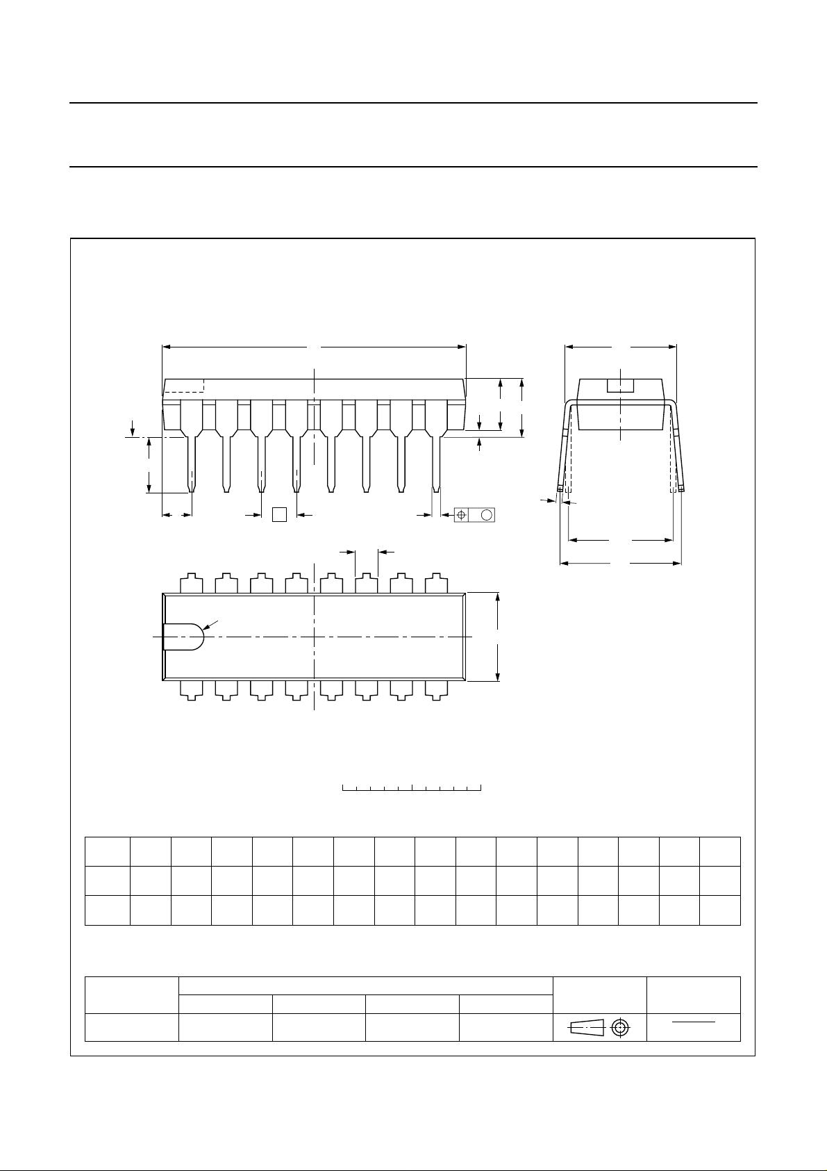
PACKAGE OUTLINE
DIP16: plastic dual in-line package; 16 leads (300 mil); long body
D
seating plane
L
Z
16
e
b
b
1
9
A
w M
TDA8442
SOT38-1
M
E
A
2
A
1
c
(e )
1
M
H
pin 1 index
1
0 5 10 mm
DIMENSIONS (inch dimensions are derived from the original mm dimensions)
A
UNIT
mm
inches
Note
1. Plastic or metal protrusions of 0.25 mm maximum per side are not included.
A
max.
4.7 0.51 3.7
OUTLINE
VERSION
SOT38-1
min.
A
1 2
max.
0.15
IEC JEDEC EIAJ
050G09 MO-001AE
b
1.40
1.14
0.055
0.045
b
0.53
0.38
0.021
0.015
1
cEe M
0.32
0.23
0.013
0.009
REFERENCES
D
21.8
21.4
0.86
0.84
8
scale
(1) (1)
6.48
6.20
0.26
0.24
E
(1)
Z
e
0.30
1
0.15
0.13
M
L
3.9
3.4
E
8.25
7.80
0.32
0.31
EUROPEAN
PROJECTION
9.5
8.3
0.37
0.33
w
H
0.2542.54 7.62
0.010.100.0200.19
ISSUE DATE
92-10-02
95-01-19
max.
2.2
0.087
March 1991 9
Page 10
Philips Semiconductors Product specification
I2C-bus interface for colour decoders
SOLDERING
Introduction
There is no soldering method that is ideal for all IC
packages. Wave soldering is often preferred when
through-hole and surface mounted components are mixed
on one printed-circuit board. However, wave soldering is
not always suitable for surface mounted ICs, or for
printed-circuits with high population densities. In these
situations reflow soldering is often used.
This text gives a very brief insight to a complex technology.
A more in-depth account of soldering ICs can be found in
“IC Package Databook”
our
Soldering by dipping or by wave
The maximum permissible temperature of the solder is
260 °C; solder at this temperature must not be in contact
DEFINITIONS
(order code 9398 652 90011).
TDA8442
with the joint for more than 5 seconds. The total contact
time of successive solder waves must not exceed
5 seconds.
The device may be mounted up to the seating plane, but
the temperature of the plastic body must not exceed the
specified maximum storage temperature (T
printed-circuit board has been pre-heated, forced cooling
may be necessary immediately after soldering to keep the
temperature within the permissible limit.
Repairing soldered joints
Apply a low voltage soldering iron (less than 24 V) to the
lead(s) of the package, below the seating plane or not
more than 2 mm above it. If the temperature of the
soldering iron bit is less than 300 °C it may remain in
contact for up to 10 seconds. If the bit temperature is
between 300 and 400 °C, contact may be up to 5 seconds.
stg max
). If the
Data sheet status
Objective specification This data sheet contains target or goal specifications for product development.
Preliminary specification This data sheet contains preliminary data; supplementary data may be published later.
Product specification This data sheet contains final product specifications.
Limiting values
Limiting values given are in accordance with the Absolute Maximum Rating System (IEC 134). Stress above one or
more of the limiting values may cause permanent damage to the device. These are stress ratings only and operation
of the device at these or at any other conditions above those given in the Characteristics sections of the specification
is not implied. Exposure to limiting values for extended periods may affect device reliability.
Application information
Where application information is given, it is advisory and does not form part of the specification.
LIFE SUPPORT APPLICATIONS
These products are not designed for use in life support appliances, devices, or systems where malfunction of these
products can reasonably be expected to result in personal injury. Philips customers using or selling these products for
use in such applications do so at their own risk and agree to fully indemnify Philips for any damages resulting from such
improper use or sale.
PURCHASE OF PHILIPS I
2
C COMPONENTS
Purchase of Philips I
components in the I2C system provided the system conforms to the I2C specification defined by
Philips. This specification can be ordered using the code 9398 393 40011.
March 1991 10
2
C components conveys a license under the Philips’ I2C patent to use the
 Loading...