

Page 1

.
LOW POW E R DIS SI PATIO N
.
PULSE WIDTH MODULATOR FOR SWITCH
MODE OPE R ATION
.
OUTPUT SINK CURRE NT UP TO 800mA
.
OUTPUT SOUR CE CURRE NT UP T O 100mA
.
PARASITIC PARABOLA SUPPRESSION
DURING VERTICAL FLYBACK
.
VERTICAL CURRENT SENSE INPUTS
GROUND COMPATIBLE
.
PROGRAMMABLE PARABOLA CURRENT
GENERATOR FOR DIFFERENT TV-TUBES
.
EXTERNAL KEYSTONE ADJUSTMENT
DESCRIPTION
The TDA8146 is a monolithic integrated circuit in a
14 pin dual-in-line plastic package.
The TDA8146 is des igned for use in th e east-wes t
pin-cushion correction by dr iving a diode modulator
in TV and monitor applications.
Since the parabola current generator is programmable the device can operate with different CRTs.
TDA8146
EAST/W EST CORRECT ION
FOR RECTANGU LAR TV-TUBES
DIP14
(Plastic Package)
ORDER CODE : TDA8146
PIN CONN E CTI O NS
May 1993
NOT USED
IGND
IREF
GND
OUT
1
IV
2
3
4
V
5
6
7
14
13
12
11
10
P4
P5
PAR
C
PW
9
Z
8
V
S
8146-01.EPS
1/5
Page 2
TDA8146
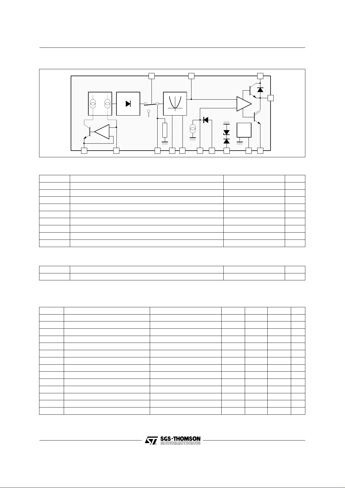
BLOCK DIAGRAM
4
∆
I
I
REF
REF
2.2V
60µA
2
13
14 13
11
10
9
5
812
7
8.2V
6
ABSOLUTE MAXIMUM RATINGS
Symbol Parameter Value Unit
I
7
I
7
V
S
V
4
V
10
V
9
V
in
T
stg
T
Output Sink Current 800 mA
Output Source Current 100 mA
Supply Voltage 33 V
Vertical Flyback Input Voltage – 0.3 to 60 V
Input Voltage at Pin 10 – 10 to V
Input Voltage at Pin 9 – 10 to 20 V
Input Voltage at all other Pins – 0.3 to V
Storage Temperature – 40 to 150 °C
Junction Temperature 0 to 150 °C
j
S
S
8146-02.EPS
V
V
8146-01.TBL
THERMAL DATA
Symbol Parameter Value Unit
R
th (j-a)
Junction-ambient Thermal Resistance Max. 80 °C/W
ELECTRICAL CHARACT E RIS TICS
(refer to test circuit V
Symbol Parameter Test Conditions Min. Typ. Max. Unit
Supply Voltage 15 24 29 V
S
I
Supply Current V
S
Reference Voltage 8.2 V
5
Saturation Voltage IO = 800mA Sink 1.2 2 V
7L
Diode Forward Voltage IO = – 800mA 1.1 1.7 V
SAT
Saturation Voltage IO = 100mA Source 0.8 1.25 V
7H
Current Sink Pin 11 40 60 80 µA
11
Zener Voltage I9 = 5mA 20 22 24 V
9
Vertical Blanking Threshold Voltage VS – 0.5 V
4T
Vertical Blanking Input Current V4 = 50V 25 50 100 µA
I
4
Reference Voltage at Pin 2 R1 = R2 = 10K 1.3 V
2
Reference Voltage at Pin 3 1.3 V
3
Parabola Voltage at Pin 12 ∆ VSE = 0 9.7 V
Parabola Voltage at Pin 12 ∆ VSE = + 0.8V 7.05 V
C
V
V
V
V
V
V
I
V
V
V
V
PARO
V
= 24V, Tj = 25oC ; unless otherwise specified)
S
= LOW 4 7 mA
out
S
VS + 0.5 V
8146-02.TBL
8146-03.TBL
2/5
Page 3

TDA8146
ELECTRICAL CHARACTERISTICS (continued)
(refer to test circuit V
Symbol Parameter Test Conditions Min. Typ. Max. Unit
K
K
K
K
K
K
Parabola Coefficient
A
Parabola Coefficient
C
Parabola Coefficient
5
Parabola Coefficient K4 =
4
Parabola Symmetry
S
Flyback Coefficient
F
TEST CIRCUIT
= 24V, Tj = 25oC ; unless otherwise specified)
S
VA
K
=
A
VB
VC
K
=
, S4 + S5 open
C
VB
VC5
K
=
5
K
S
K
F
V
, S4 or S5 Closed
VC
VC4
, S4 + S5 Closed 1.17
VC
VC
=
VD
VC
=
, V4 = 15V
VD
5kΩ
0.25
1.75
1.07
0.94 1.0 1.06
1.0
24V
8V
8146-04.TBL
4
I
∆
I
REF
REF
2.2V
60µA
2
10k
V
Ω
SE
R2R1
10kΩ
13 5 6
14 13
S4
11
S5
VV
10
9
8.2V
R
REF
Ω
100k
812
D1
7
V
V
S
8146-03.EPS
3/5
Page 4

TDA8146
PARABOLA CHARACT ERI STICS
V
C4
C5
V
V
V
PAR
V
V
A
V
B
C
PAR
9.6V
9V
8V
VV
D
F
APPLICATION DIAGRAM
18kΩ
S4 S5
3.3MΩ
1 2 3
Ω
820k
KEYSTONE
ADJUSTEMNT
2.2MΩ
VERTICAL
YOKE
100nF
4
10kΩ
10kΩ
1%
1%
32 54
1
VERTICAL
FLYBACK
2.2nF
5 6 7
100kΩ
7V
0-0.3V-0.6V-0.8V +0.8V V
Line Size
Adjustment
2.2kΩ
during
flyback
891011121314
47kΩ
4.7k
E-W Correction
15mH
Ω
1nF
SE
1.5k
8146-04.EPS
Ω
F
µ
220
7
6
100nF
HORIZONTAL
FLYBACK
V
S
4/5
1.6 V
PP
8146-05.EPS
Page 5

PACKA G E MECHANICAL DATA
14 PINS - PLASTIC DIP
TDA8146
I
a1
L
e3
B
e
Z
Z
b
b1
E
D
14 8
F
17
Dimensions
Min. Typ. Max. Min. Typ. Max.
a1 0.51 0.020
B 1.39 1.65 0.055 0.065
b 0.5 0.020
b1 0.25 0.010
D 20 0.787
E 8.5 0.335
e 2.54 0.100
e3 15.24 0.600
F 7.1 0.2 80
i 5.1 0.2 01
L 3.3 0.130
Z 1.27 2.54 0.050 0.100
Millimeters Inches
PM-DIP14.EPS
DIP14.TBL
Information furnished is believed to be accurate and reliable. However, SGS-THOMSON Microelectronics assumes no responsibility
for the consequences of use of such information nor for any infringement of patents or other rights of third parties which may result
from its use. No licence is granted by implication or otherwi se under any patent or patent rights of SGS-THOMSON Microelectronics.
Specifications mentioned in this publication are subject to change without notice. This publication supersedes and replaces all
information previously suppli ed. SGS-THOMSON Microele ctronics products are not authorized for use as critical components in life
support devices or systems without express written approval of SGS-THOMSON Microelectronics.
© 1994 SGS-THOMSON Microelectronics - All Rights Reserved
2
Purchase of I
2
C Patent. Rights to use these components in a I2C system, is granted provided that the system conforms to
I
Australia - Brazil - China - France - Germany - Hong Kong - Italy - Japan - Korea - Malaysia - Malta - Morocco
The Netherlands - Singapore - Spain - Sweden - Switzerland - Taiwan - Thailand - United Kingdom - U.S.A.
C Components of SGS-THOMSON Microelectronics, conveys a license under the Philips
2
C Standard Specifications as defined by Philips.
the I
SGS-THOMSON Microelectronics G ROUP OF COMPANIES
5/5
 Loading...